EP3495755A1 - Refrigerant container - Google Patents
Refrigerant container Download PDFInfo
- Publication number
- EP3495755A1 EP3495755A1 EP17885752.0A EP17885752A EP3495755A1 EP 3495755 A1 EP3495755 A1 EP 3495755A1 EP 17885752 A EP17885752 A EP 17885752A EP 3495755 A1 EP3495755 A1 EP 3495755A1
- Authority
- EP
- European Patent Office
- Prior art keywords
- gas
- liquid
- phase
- refrigerant
- tank
- Prior art date
- Legal status (The legal status is an assumption and is not a legal conclusion. Google has not performed a legal analysis and makes no representation as to the accuracy of the status listed.)
- Granted
Links
Images



Classifications
-
- B—PERFORMING OPERATIONS; TRANSPORTING
- B60—VEHICLES IN GENERAL
- B60H—ARRANGEMENTS OF HEATING, COOLING, VENTILATING OR OTHER AIR-TREATING DEVICES SPECIALLY ADAPTED FOR PASSENGER OR GOODS SPACES OF VEHICLES
- B60H1/00—Heating, cooling or ventilating devices
- B60H1/32—Cooling devices
- B60H1/3204—Cooling devices using compression
- B60H1/3226—Self-contained devices, i.e. including own drive motor
-
- F—MECHANICAL ENGINEERING; LIGHTING; HEATING; WEAPONS; BLASTING
- F25—REFRIGERATION OR COOLING; COMBINED HEATING AND REFRIGERATION SYSTEMS; HEAT PUMP SYSTEMS; MANUFACTURE OR STORAGE OF ICE; LIQUEFACTION SOLIDIFICATION OF GASES
- F25B—REFRIGERATION MACHINES, PLANTS OR SYSTEMS; COMBINED HEATING AND REFRIGERATION SYSTEMS; HEAT PUMP SYSTEMS
- F25B43/00—Arrangements for separating or purifying gases or liquids; Arrangements for vaporising the residuum of liquid refrigerant, e.g. by heat
-
- B—PERFORMING OPERATIONS; TRANSPORTING
- B60—VEHICLES IN GENERAL
- B60H—ARRANGEMENTS OF HEATING, COOLING, VENTILATING OR OTHER AIR-TREATING DEVICES SPECIALLY ADAPTED FOR PASSENGER OR GOODS SPACES OF VEHICLES
- B60H1/00—Heating, cooling or ventilating devices
- B60H1/32—Cooling devices
-
- B—PERFORMING OPERATIONS; TRANSPORTING
- B60—VEHICLES IN GENERAL
- B60H—ARRANGEMENTS OF HEATING, COOLING, VENTILATING OR OTHER AIR-TREATING DEVICES SPECIALLY ADAPTED FOR PASSENGER OR GOODS SPACES OF VEHICLES
- B60H1/00—Heating, cooling or ventilating devices
- B60H1/32—Cooling devices
- B60H1/3204—Cooling devices using compression
- B60H1/3229—Cooling devices using compression characterised by constructional features, e.g. housings, mountings, conversion systems
-
- F—MECHANICAL ENGINEERING; LIGHTING; HEATING; WEAPONS; BLASTING
- F25—REFRIGERATION OR COOLING; COMBINED HEATING AND REFRIGERATION SYSTEMS; HEAT PUMP SYSTEMS; MANUFACTURE OR STORAGE OF ICE; LIQUEFACTION SOLIDIFICATION OF GASES
- F25B—REFRIGERATION MACHINES, PLANTS OR SYSTEMS; COMBINED HEATING AND REFRIGERATION SYSTEMS; HEAT PUMP SYSTEMS
- F25B43/00—Arrangements for separating or purifying gases or liquids; Arrangements for vaporising the residuum of liquid refrigerant, e.g. by heat
- F25B43/003—Filters
-
- F—MECHANICAL ENGINEERING; LIGHTING; HEATING; WEAPONS; BLASTING
- F25—REFRIGERATION OR COOLING; COMBINED HEATING AND REFRIGERATION SYSTEMS; HEAT PUMP SYSTEMS; MANUFACTURE OR STORAGE OF ICE; LIQUEFACTION SOLIDIFICATION OF GASES
- F25B—REFRIGERATION MACHINES, PLANTS OR SYSTEMS; COMBINED HEATING AND REFRIGERATION SYSTEMS; HEAT PUMP SYSTEMS
- F25B43/00—Arrangements for separating or purifying gases or liquids; Arrangements for vaporising the residuum of liquid refrigerant, e.g. by heat
- F25B43/006—Accumulators
-
- F—MECHANICAL ENGINEERING; LIGHTING; HEATING; WEAPONS; BLASTING
- F25—REFRIGERATION OR COOLING; COMBINED HEATING AND REFRIGERATION SYSTEMS; HEAT PUMP SYSTEMS; MANUFACTURE OR STORAGE OF ICE; LIQUEFACTION SOLIDIFICATION OF GASES
- F25B—REFRIGERATION MACHINES, PLANTS OR SYSTEMS; COMBINED HEATING AND REFRIGERATION SYSTEMS; HEAT PUMP SYSTEMS
- F25B43/00—Arrangements for separating or purifying gases or liquids; Arrangements for vaporising the residuum of liquid refrigerant, e.g. by heat
- F25B43/04—Arrangements for separating or purifying gases or liquids; Arrangements for vaporising the residuum of liquid refrigerant, e.g. by heat for withdrawing non-condensible gases
- F25B43/043—Arrangements for separating or purifying gases or liquids; Arrangements for vaporising the residuum of liquid refrigerant, e.g. by heat for withdrawing non-condensible gases for compression type systems
-
- B—PERFORMING OPERATIONS; TRANSPORTING
- B60—VEHICLES IN GENERAL
- B60H—ARRANGEMENTS OF HEATING, COOLING, VENTILATING OR OTHER AIR-TREATING DEVICES SPECIALLY ADAPTED FOR PASSENGER OR GOODS SPACES OF VEHICLES
- B60H1/00—Heating, cooling or ventilating devices
- B60H1/32—Cooling devices
- B60H2001/3286—Constructional features
-
- F—MECHANICAL ENGINEERING; LIGHTING; HEATING; WEAPONS; BLASTING
- F25—REFRIGERATION OR COOLING; COMBINED HEATING AND REFRIGERATION SYSTEMS; HEAT PUMP SYSTEMS; MANUFACTURE OR STORAGE OF ICE; LIQUEFACTION SOLIDIFICATION OF GASES
- F25B—REFRIGERATION MACHINES, PLANTS OR SYSTEMS; COMBINED HEATING AND REFRIGERATION SYSTEMS; HEAT PUMP SYSTEMS
- F25B2400/00—Component parts or details not otherwise provided for in this subclass
- F25B2400/16—Receivers
-
- F—MECHANICAL ENGINEERING; LIGHTING; HEATING; WEAPONS; BLASTING
- F25—REFRIGERATION OR COOLING; COMBINED HEATING AND REFRIGERATION SYSTEMS; HEAT PUMP SYSTEMS; MANUFACTURE OR STORAGE OF ICE; LIQUEFACTION SOLIDIFICATION OF GASES
- F25B—REFRIGERATION MACHINES, PLANTS OR SYSTEMS; COMBINED HEATING AND REFRIGERATION SYSTEMS; HEAT PUMP SYSTEMS
- F25B2500/00—Problems to be solved
- F25B2500/01—Geometry problems, e.g. for reducing size
-
- F—MECHANICAL ENGINEERING; LIGHTING; HEATING; WEAPONS; BLASTING
- F25—REFRIGERATION OR COOLING; COMBINED HEATING AND REFRIGERATION SYSTEMS; HEAT PUMP SYSTEMS; MANUFACTURE OR STORAGE OF ICE; LIQUEFACTION SOLIDIFICATION OF GASES
- F25B—REFRIGERATION MACHINES, PLANTS OR SYSTEMS; COMBINED HEATING AND REFRIGERATION SYSTEMS; HEAT PUMP SYSTEMS
- F25B2500/00—Problems to be solved
- F25B2500/18—Optimization, e.g. high integration of refrigeration components
Definitions
- the present invention relates to refrigerant containers for use in the heat pump refrigeration cycles of car air-conditioners and the like (hereinafter referred to as heat pump systems).
- the invention relates to a refrigerant container that is adapted to separate a refrigerant into a liquid-phase refrigerant and a gas-phase refrigerant and has both the function of a receiver that guides only the liquid-phase refrigerant after the separation to the side of an expansion valve, and the function of an accumulator that guides the gas-phase refrigerant (plus oil) after the separation to the suction side of a compressor.
- Patent Literature 1 As a heat pump system forming a car air-conditioner or the like, as described in Patent Literature 1, for example, there is known a system that includes, in addition to a compressor, a condenser, an evaporator, an expansion valve, a flow channel switching valve, an on-off valve, and the like, a receiver adapted to perform gas-liquid separation for guiding only a liquid-phase refrigerant after the separation to the expansion valve, and an accumulator adapted to perform gas-liquid separation for guiding a gas-phase refrigerant (including oil) after the separation to the suction side of the compressor.
- a system that includes, in addition to a compressor, a condenser, an evaporator, an expansion valve, a flow channel switching valve, an on-off valve, and the like, a receiver adapted to perform gas-liquid separation for guiding only a liquid-phase refrigerant after the separation to the expansion valve, and an accumulator adapted to perform gas-liquid separation for guiding
- Patent Literature 2 As a measure to meet the aforementioned demand, it is considered to be effective to, as described in Patent Literature 2 (or Fig. 16 thereof), for example, allow a single tank (i.e., a container) to separate a refrigerant therein into a liquid-phase refrigerant and a gas-phase refrigerant, and to have the function of a receiver that guides only the liquid-phase refrigerant after the separation to the side of an expansion valve, and the function of an accumulator that guides the gas-phase refrigerant after the separation to a suction side of a compressor.
- a single tank i.e., a container
- a receiver that guides only the liquid-phase refrigerant after the separation to the side of an expansion valve
- an accumulator that guides the gas-phase refrigerant after the separation to a suction side of a compressor.
- Patent Literature 2 only describes that a single container functions as a receiver and an accumulator, and does not at all disclose the internal structure of the container or the like.
- the present invention has been made in view of the foregoing, and it is an object of the present invention to provide a refrigerant container having a rational structure with a small number of components, the container having both the functions of a receiver and an accumulator.
- a refrigerant container in accordance with the present invention basically includes a tank capable of temporarily storing a refrigerant; and a gas/liquid inlet port, a liquid-phase outlet port, and a gas-phase outlet port that are provided in an upper portion of the tank.
- the refrigerant container is adapted to separate a refrigerant introduced through the gas/liquid inlet port into a liquid-phase refrigerant and a gas-phase refrigerant, and has the function of a receiver that guides only the liquid-phase refrigerant after the separation to the side of an expansion valve via the liquid-phase outlet port, and the function of an accumulator that guides the gas-phase refrigerant after the separation to a suction side of a compressor via the gas-phase outlet port together with oil contained in the liquid-phase refrigerant.
- an upper-face opening of the tank is hermetically closed by a cap member that includes the gas/liquid inlet port, the liquid-phase outlet port, and the gas-phase outlet port therein; a gas-liquid separator is disposed below the cap member in the tank, the gas-liquid separator having the shape of a conical hat or an inverted wide bowl and having a smaller diameter than the inside diameter of the tank; a gas/liquid outlet pipe is disposed between the cap member and the bottom of the tank, the gas/liquid outlet pipe being segmented into a downward-feed flow channel portion, an upward-feed inner pipe portion, and a liquid-phase inner pipe portion; and a strainer is provided at the lower end of the gas/liquid outlet pipe.
- the downward-feed flow channel portion is open at its upper end to the lower portion of the gas-liquid separator and is adapted to guide the gas-phase refrigerant in the upper portion of the tank to a portion around the bottom of the tank;
- the upward-feed inner pipe portion protrudes upward at its upper portion beyond the upper end of the downward-feed flow channel portion and is adapted to guide the gas-phase refrigerant from the downward-feed flow channel portion to the gas-phase outlet port;
- the liquid-phase inner pipe portion is adapted to guide the liquid-phase refrigerant around the bottom of the tank to the liquid-phase outlet port.
- an on-off valve which is adapted to open or close a flow channel for guiding the gas-phase refrigerant in a portion that functions as the accumulator, is provided.
- the on-off valve is disposed above the tank.
- the on-off valve is an electromagnetic valve.
- the refrigerant container in accordance with the present invention has both the functions of a receiver and an accumulator, and the receiver and the accumulator can share the tank portion, the inlet port portion, the gas-liquid separator portion, the outlet pipe portion, the strainer portion, and the like in common. Therefore, a rational structure with a small number of components can be provided, and thus, in a heat pump system that adopts such a refrigerant container, a reduction in the space occupied by the entire system as well as a reduction in the number of components is achieved, so that a reduction in the cost and size can be effectively achieved.
- the refrigerant container is provided with an on-off valve so as to be able to switch between a state in which the container functions as a receiver and a state in which the container functions as an accumulator in accordance with the operating state of the system based on opening/closing (i.e., ON or OFF) of the on-off valve, the pipe lines and the like of the system can be simplified in comparison with when the on-off valve is provided outside of the container.
- Fig. 1 is a top view of an embodiment of a refrigerant container in accordance with the present invention.
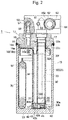
- Fig. 2 is a partially cutaway longitudinal cross-sectional view taken in the direction of arrows A-C passing through O in Fig. 1 .
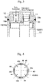
- Fig. 3 is a partially cutaway cross-sectional view taken in the direction of arrows B-C passing through O in Fig. 1 .
- a refrigerant container 1 of an embodiment illustrated in the drawings is used for a heat pump system forming a car air-conditioner for an electric vehicle, for example.
- the refrigerant container 1 includes a cylindrical tank 10 having a bottom and made of metal, such as stainless steel or aluminum alloy, and an upper-face opening of the tank 10 is hermetically closed by a cap member 12 made of the same metal.
- the refrigerant container 1 of this embodiment is placed in a vertical position as illustrated in the drawings, for example. That is, the refrigerant container 1 is placed with the cap member 12 located on the upper side and the bottom 13 of the tank 10 located on the lower side.
- the cap member 12 includes a gas/liquid inlet port 15 and a gas-phase outlet port 17 with a stepped large diameter, which are arranged side by side in the cap member 12 while penetrating through the cap member 12 such that they are open on the top and bottom sides thereof, and also includes a liquid-phase outlet port 16 with a relatively small diameter.
- the liquid-phase outlet port 16 has at its lower portion an L-shaped passage portion 16a lying on its side and having an opening at one end (i.e., the lower end) thereof. The other end (i.e., an opening at the other end facing a lateral side) of the passage portion 16a is closed by a plug 16b.
- a connection adapter 50 which has a partially cutaway rectangular shape in plan view (i.e., a portion covering the gas/liquid inlet port 15 is cut away) and has a rectangular shape in front view, is hermetically attached to the upper side of the cap member 12 with bolts 51 and the like such that it covers a portion excluding the gas/liquid inlet port 15 of the cap member 12.
- the connection adapter 50 functions as a valve body of an on-off valve 65 described below.
- cap member 12 is provided with an internal thread 52 for screwing a flange portion of an inlet conduit therein
- connection adapter 50 is provided with internal threads 53, 53 for screwing the flange portion of the inlet conduit and a flange portion of an outlet conduit described below therein (the internal structure of the connection adapter 50 is described in detail below).
- a gas-liquid separator 18 in the shape of a conical hat or an inverted wide bowl having a slightly smaller diameter than the inside diameter of the tank 10 is disposed below the cap member 12 such that the upper face of the gas-liquid separator 18 partially abuts the lower face of the cap member 12.
- the upper end of the gas/liquid outlet pipe 30 is connected to the lower portion of the gas-phase outlet port 17 of the cap member 12.
- the on-off valve 65 is closed (i.e., power is OFF) and the opening at one end of the gas-phase circulation port 63 is closed by the valve element 65c. Therefore, the flow channel for guiding the gas-phase refrigerant to the horizontal hole/outlet port 64 via the upper space of the tank 10 ⁇ the downward-feed flow channel portions 32 ⁇ the cutout opening 33d ⁇ the upward-feed inner pipe portion 33 ⁇ the gas-phase outlet port 17 ⁇ the vertical hole/outlet port 61 ⁇ the valve-element sliding hole 62 ⁇ the gas-phase circulation port 63 is blocked. Instead, a gas-phase refrigerant from the evaporator is guided to the suction side of the compressor via the gas-phase circulation port 63 ⁇ the horizontal hole/outlet port 64.
Landscapes
- Engineering & Computer Science (AREA)
- Physics & Mathematics (AREA)
- Mechanical Engineering (AREA)
- Thermal Sciences (AREA)
- Chemical & Material Sciences (AREA)
- Analytical Chemistry (AREA)
- Power Engineering (AREA)
- General Engineering & Computer Science (AREA)
- Air-Conditioning For Vehicles (AREA)
- Compressor (AREA)
Abstract
Description
- The present invention relates to refrigerant containers for use in the heat pump refrigeration cycles of car air-conditioners and the like (hereinafter referred to as heat pump systems). In particular, the invention relates to a refrigerant container that is adapted to separate a refrigerant into a liquid-phase refrigerant and a gas-phase refrigerant and has both the function of a receiver that guides only the liquid-phase refrigerant after the separation to the side of an expansion valve, and the function of an accumulator that guides the gas-phase refrigerant (plus oil) after the separation to the suction side of a compressor.
- As a heat pump system forming a car air-conditioner or the like, as described in
Patent Literature 1, for example, there is known a system that includes, in addition to a compressor, a condenser, an evaporator, an expansion valve, a flow channel switching valve, an on-off valve, and the like, a receiver adapted to perform gas-liquid separation for guiding only a liquid-phase refrigerant after the separation to the expansion valve, and an accumulator adapted to perform gas-liquid separation for guiding a gas-phase refrigerant (including oil) after the separation to the suction side of the compressor. - In such a heat pump system with a receiver and an accumulator, a reduction in the space occupied by the entire system as well as a reduction in the number of components is demanded.
-
- [Patent Literature 1]
JP 2013-184596 A - [Patent Literature 2]
JP 2012-136147 A - As a measure to meet the aforementioned demand, it is considered to be effective to, as described in Patent Literature 2 (or Fig. 16 thereof), for example, allow a single tank (i.e., a container) to separate a refrigerant therein into a liquid-phase refrigerant and a gas-phase refrigerant, and to have the function of a receiver that guides only the liquid-phase refrigerant after the separation to the side of an expansion valve, and the function of an accumulator that guides the gas-phase refrigerant after the separation to a suction side of a compressor.
- However, Patent Literature 2 only describes that a single container functions as a receiver and an accumulator, and does not at all disclose the internal structure of the container or the like.
- The present invention has been made in view of the foregoing, and it is an object of the present invention to provide a refrigerant container having a rational structure with a small number of components, the container having both the functions of a receiver and an accumulator.
- In order to solve the aforementioned object, a refrigerant container in accordance with the present invention basically includes a tank capable of temporarily storing a refrigerant; and a gas/liquid inlet port, a liquid-phase outlet port, and a gas-phase outlet port that are provided in an upper portion of the tank. The refrigerant container is adapted to separate a refrigerant introduced through the gas/liquid inlet port into a liquid-phase refrigerant and a gas-phase refrigerant, and has the function of a receiver that guides only the liquid-phase refrigerant after the separation to the side of an expansion valve via the liquid-phase outlet port, and the function of an accumulator that guides the gas-phase refrigerant after the separation to a suction side of a compressor via the gas-phase outlet port together with oil contained in the liquid-phase refrigerant.
- In a preferred aspect, an upper-face opening of the tank is hermetically closed by a cap member that includes the gas/liquid inlet port, the liquid-phase outlet port, and the gas-phase outlet port therein; a gas-liquid separator is disposed below the cap member in the tank, the gas-liquid separator having the shape of a conical hat or an inverted wide bowl and having a smaller diameter than the inside diameter of the tank; a gas/liquid outlet pipe is disposed between the cap member and the bottom of the tank, the gas/liquid outlet pipe being segmented into a downward-feed flow channel portion, an upward-feed inner pipe portion, and a liquid-phase inner pipe portion; and a strainer is provided at the lower end of the gas/liquid outlet pipe. Specifically, the downward-feed flow channel portion is open at its upper end to the lower portion of the gas-liquid separator and is adapted to guide the gas-phase refrigerant in the upper portion of the tank to a portion around the bottom of the tank; the upward-feed inner pipe portion protrudes upward at its upper portion beyond the upper end of the downward-feed flow channel portion and is adapted to guide the gas-phase refrigerant from the downward-feed flow channel portion to the gas-phase outlet port; and the liquid-phase inner pipe portion is adapted to guide the liquid-phase refrigerant around the bottom of the tank to the liquid-phase outlet port.
- In a further preferred aspect, the gas-liquid separator is sandwiched between the cap member and the gas/liquid outlet pipe.
- In still another preferred aspect, an on-off valve, which is adapted to open or close a flow channel for guiding the gas-phase refrigerant in a portion that functions as the accumulator, is provided.
- In a further preferred aspect, the on-off valve is disposed above the tank.
- In a further preferred aspect, the on-off valve is an electromagnetic valve.
- The refrigerant container in accordance with the present invention has both the functions of a receiver and an accumulator, and the receiver and the accumulator can share the tank portion, the inlet port portion, the gas-liquid separator portion, the outlet pipe portion, the strainer portion, and the like in common. Therefore, a rational structure with a small number of components can be provided, and thus, in a heat pump system that adopts such a refrigerant container, a reduction in the space occupied by the entire system as well as a reduction in the number of components is achieved, so that a reduction in the cost and size can be effectively achieved.
- In addition, since the refrigerant container is provided with an on-off valve so as to be able to switch between a state in which the container functions as a receiver and a state in which the container functions as an accumulator in accordance with the operating state of the system based on opening/closing (i.e., ON or OFF) of the on-off valve, the pipe lines and the like of the system can be simplified in comparison with when the on-off valve is provided outside of the container.
-
-
Fig. 1 is a top view of an embodiment of a refrigerant container in accordance with the present invention. -
Fig. 2 is a partially cutaway longitudinal cross-sectional view taken in the direction of arrows A-C passing through O inFig. 1 . -
Fig. 3 is a partially cutaway cross-sectional view taken in the direction of arrows B-C passing through O inFig. 1 . -
Fig. 4 is a cross-sectional view taken in the direction of arrows V-V inFig. 2 . -
Fig. 5 is a longitudinal cross-sectional view illustrating a state before a gas/liquid outlet pipe illustrated inFig. 2 is attached to a tank. -
Fig. 6A is a top view of the gas/liquid outlet pipe illustrated inFig. 5 . -
Fig. 6B is a horizontal cross-sectional view of an intermediate portion of the gas/liquid outlet pipe illustrated inFig. 5 . -
Fig. 6C is a bottom view of the gas/liquid outlet pipe illustrated inFig. 5 . -
Fig. 6D is a plan view of a base plate securely attached to the lower end of the gas/liquid outlet pipe illustrated inFig. 5 . -
Fig. 7A is a partially cutaway top view illustrating a flow of a refrigerant during the cooling operation of the refrigerant container of the embodiment. -
Fig. 7B is a partially cutaway cross-sectional view illustrating a flow of a refrigerant in the cooling operation of the refrigerant container of the embodiment. -
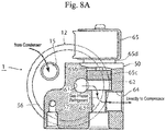
Fig. 8A is a partially cutaway top view illustrating a flow of a refrigerant during the heating operation of the refrigerant container of the embodiment. -
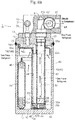
Fig. 8B is a partially cutaway cross-sectional view illustrating a flow of a refrigerant during the heating operation of the refrigerant container of the embodiment. - Hereinafter, embodiments of the present invention will be described with reference to the accompanying drawings.
-
Fig. 1 is a top view of an embodiment of a refrigerant container in accordance with the present invention.Fig. 2 is a partially cutaway longitudinal cross-sectional view taken in the direction of arrows A-C passing through O inFig. 1 .Fig. 3 is a partially cutaway cross-sectional view taken in the direction of arrows B-C passing through O inFig. 1 . - A
refrigerant container 1 of an embodiment illustrated in the drawings is used for a heat pump system forming a car air-conditioner for an electric vehicle, for example. Therefrigerant container 1 includes acylindrical tank 10 having a bottom and made of metal, such as stainless steel or aluminum alloy, and an upper-face opening of thetank 10 is hermetically closed by acap member 12 made of the same metal. It should be noted that therefrigerant container 1 of this embodiment is placed in a vertical position as illustrated in the drawings, for example. That is, therefrigerant container 1 is placed with thecap member 12 located on the upper side and thebottom 13 of thetank 10 located on the lower side. - The
cap member 12 includes a gas/liquid inlet port 15 and a gas-phase outlet port 17 with a stepped large diameter, which are arranged side by side in thecap member 12 while penetrating through thecap member 12 such that they are open on the top and bottom sides thereof, and also includes a liquid-phase outlet port 16 with a relatively small diameter. The liquid-phase outlet port 16 has at its lower portion an L-shaped passage portion 16a lying on its side and having an opening at one end (i.e., the lower end) thereof. The other end (i.e., an opening at the other end facing a lateral side) of thepassage portion 16a is closed by aplug 16b. - A
connection adapter 50, which has a partially cutaway rectangular shape in plan view (i.e., a portion covering the gas/liquid inlet port 15 is cut away) and has a rectangular shape in front view, is hermetically attached to the upper side of thecap member 12 withbolts 51 and the like such that it covers a portion excluding the gas/liquid inlet port 15 of thecap member 12. The connection adapter 50 functions as a valve body of an on-offvalve 65 described below. It should be noted that thecap member 12 is provided with aninternal thread 52 for screwing a flange portion of an inlet conduit therein, and theconnection adapter 50 is provided withinternal threads connection adapter 50 is described in detail below). - A gas-
liquid separator 18 in the shape of a conical hat or an inverted wide bowl having a slightly smaller diameter than the inside diameter of thetank 10 is disposed below thecap member 12 such that the upper face of the gas-liquid separator 18 partially abuts the lower face of thecap member 12. - In addition, the upper end of the gas/
liquid outlet pipe 30 is connected to the lower portion of the gas-phase outlet port 17 of thecap member 12. - Specifically, the gas/
liquid outlet pipe 30 is produced through extrusion molding using aluminum alloy or the like as a material, for example, and as is clearly seen inFigs. 5 and6A to 6D , which illustrate a state before the gas/liquid outlet pipe 30 is attached to thetank 10, in addition toFig. 2 , the gas/liquid outlet pipe 30 has anouter pipe portion 31 whose outer shape has a circular cross-section. The inside of theouter pipe portion 31 is segmented into a pair of right and left (front and back in the drawing) downward-feedflow channel portions liquid separator 18 and has the shape of a wing in plan view, for guiding a gas-phase refrigerant in the upper portion of thetank 10 to a portion around the bottom 13 of thetank 10; an upward-feedinner pipe portion 33 having a relatively large diameter and protruding upward at its upper portion beyond the upper ends of the downward-feedflow channel portions flow channel portions phase outlet port 17; and a liquid-phaseinner pipe portion 34 having a relatively small diameter for guiding a liquid-phase refrigerant around the bottom 13 of thetank 10 to the liquid-phase outlet port 16. - It should be noted that the height positions of upper end faces 32A, 33A, 34A of the downward-feed
flow channel portions inner pipe portion 33, and the liquid-phaseinner pipe portion 34 satisfy the following relationship: the upward-feed inner pipe portion 33 (highest) > the liquid-phase inner pipe portion 34 (second highest) > the downward-feed flow channel portions 32 (lowest). In addition, apressure equalizing hole 33f is provided in the upward-feedinner pipe portion 33 at a height around the gas-liquid separator 18 so as to prevent a backflow of a liquid to the compressor side when the operation of the system is stopped (ON → OFF). - An
upper end 33a of the upward-feedinner pipe portion 33 of the gas/liquid outlet pipe 30 is thin, and the thinupper end 33a is passed through a through-hole 19 provided in the gas-liquid separator 18 and through the lower portion of the gas-phase outlet port 17, and then, the upper portion of the thinupper end 33a is fixed in anannular recess portion 17a formed in the intermediate portion of the gas-phase outlet port 17 such that the diameter of the upper portion is widened. Accordingly, the gas-liquid separator 18 is locked by being sandwiched between astep portion 33b provided at the lower end of the thinupper end 33a (and the upper end of the liquid-phase inner pipe portion 34) and the lower end face of thecap member 12, and also, the gas/liquid outlet pipe 30 is securely held by thecap member 12. - Meanwhile, the lowermost end of the gas/
liquid outlet pipe 30 is athin portion 30b for swaging to which abase plate 35 is adapted to be fixed through swaging, and a lower-endthin portion 30a, which is slightly thicker than thethin portion 30b for swaging and is adapted to be securely fitted into anupper portion 42a with a stepped inner periphery of acase 42 of a strainer 40 (which is described below) through press fitting or the like, is provided above thethin portion 30b for swaging. It should be noted that the lower end of a partition wall, which separates the upward-feedinner pipe portion 33 from the pair of right and left (front and back in the drawing) downward-feedflow channel portions cutout opening 33d that allows the upward-feedinner pipe portion 33 and the downward-feedflow channel portions - An
oil return hole 36 is provided in thebase plate 35 fixed to the lower end (i.e., thethin portion 30b for swaging) of the gas/liquid outlet pipe 30 through swaging, at a position along the center line of the upward-feedinner pipe portion 33 or a region on the inner side of the upward-feedinner pipe portion 33. In addition, aliquid suction port 37 with substantially the same diameter as that of the liquid-phaseinner pipe portion 34 is provided in a portion of thebase plate 35 facing the liquid-phaseinner pipe portion 34. The diameter of theoil return hole 36 is set to about 1 mm, for example. - The upper end of the liquid-phase
inner pipe portion 34 is provided with a thin externalfitting portion 34a, and the lower end of thepassage portion 16a of the liquid-phase outlet port 16 of thecap member 12 is provided with a thin internalfitting portion 16c. The thin externalfitting portion 34a and the thin internalfitting portion 16c are fitted together, and an O-ring 38 is inserted between the lower-end step portion of the thin externalfitting portion 34a and the upper-end step portion of the thin internalfitting portion 16c. Accordingly, the liquid-phaseinner pipe portion 34 and the liquid-phase outlet port 16 are hermetically connected together. - The gas-
liquid separator 18 is made of metal such as stainless steel or aluminum alloy, and is disposed at a position lower than the lower end face of the cap member 12 (or the gas/liquid inlet port 15 therein) by a predetermined distance so as to cover the upper-end openings of the downward-feedflow channel portions 32 of the gas/liquid outlet pipe 30. The gas-liquid separator 18 is provided with the through-hole 19 through which the upward-feedinner pipe portion 33 of the gas/liquid outlet pipe 30 and the lower side portion of thepassage portion 16a of the liquid-phase outlet port 16 pass, and has a disk-shapedceiling portion 18a at a position higher than the upper-end openings of the downward-feedflow channel portions 32 by a predetermined distance so as to be opposite the upper-end openings of the downward-feedflow channel portions 32, and a cylindricalperipheral wall portion 18b that is continuous with the outer periphery of theceiling portion 18a and faces downward. - Meanwhile, the
strainer 40 is provided at the lower end of the gas/liquid outlet pipe 30. - Specifically, the
strainer 40 is fixed by being placed on the bottom 13 of thetank 10, and includes, as is clearly seen inFig. 4 , acylindrical case 42 having a bottom and made of synthetic resin, and acylindrical mesh filter 45 integrally formed with thecase 42 trough insert molding or the like. Themesh filter 45 is made of a metallic mesh or a mesh material of synthetic resin, for example. - The
case 42 of thestrainer 40 includes anupper portion 42a with a stepped inner periphery in which the lower end of the gas/liquid outlet pipe 30 is adapted to be securely fitted, abase plate portion 42c, and fourcolumnar portions 42b that are disposed in upright position on the outer periphery of thebase plate portion 42c at equal angular intervals and connect to theupper portion 42a. The outer periphery of thebase plate portion 42c is provided with an annular connecting band portion, and the upper and lower ends of themesh filter 45 are secured to the connecting band portion and the lower side of theupper portion 42a. That is, fourwindows 44 that are rectangular in side view are defined between the fourcolumnar portions 42b, and themesh filter 45 is put in the portion of eachwindow 44 in a tensed manner. It should be noted that themesh filter 45 may be integrally formed with thecase 42 through insert molding during molding of thecase 42. In addition, although the fourcolumnar portions 42b are provided with slops for demolding, the widths of the fourcolumnar portions 42b in the radial direction are set substantially equal. Further, the method for providing themesh filter 45 on thecase 42 is not limited to the method described above. - A
bag 70 with a predetermined height, which contains desiccants M therein, is disposed in thetank 10 by being placed on the bottom 13 of thetank 10 along the inner periphery of thetank 10 so that moisture in the refrigerant is absorbed and removed by the desiccants M. Thebag 70 is made of a fabric such as felt with a ventilation property, a water permeation property, and a desired shape retention property, and is filled with granular desiccants M almost entirely. - A left end on the front side of the
connection adapter 50 attached to thecap member 12 of thetank 10 with the aforementioned internal structure is provided with, as is clearly seen inFigs. 7A ,7B ,8A , and8B in addition toFigs. 1 and2 , a vertical hole/outlet port 56 that has a vertical hole continuous with the liquid-phase outlet port 16, and a horizontal hole/outlet port 57 that has a horizontal hole continuous with the upper end of the vertical hole/outlet port 56. The horizontal hole/outlet port 57 is open to the front side of theconnection adapter 50, and is adapted to connect to a conduit for guiding a liquid-phase refrigerant to an expansion valve. - Around the center portion in plan view of the
connection adapter 50, a vertical hole/outlet port 61 with a relatively large diameter having a vertical hole continuous with the gas-phase outlet port 17, is provided, and a valve-element sliding hole 62 with a relatively large diameter having a horizontal hole that is open on the rear side is provided so that its front-side end overlaps the vertical hole/outlet port 61. A portion of the front-side end of the valve-element sliding hole 62 that overlaps the vertical hole/outlet port 61 is a cutout opening, and the cutout opening allows the vertical hole/outlet port 61 and the valve-element sliding hole 62 to communicate with each other. - On the front side of the
connection adapter 50 coaxial with the valve-element sliding hole 62, a gas-phase circulation port 63 having a stepped horizontal hole with a smaller diameter than that of the valve-element sliding hole 62 is provided that has one end side (i.e., the rear side) open to the bottom face (i.e., the front-side face) of the valve-element sliding hole 62, and the other end side open to the front side of theconnection adapter 50. The gas-phase circulation port 63 is adapted to connect to a conduit for guiding a gas-phase refrigerant from an evaporator to a suction side of a compressor. - Further, the
connection adapter 50 is provided with a horizontal hole/outlet port 64 having a horizontal hole with a relatively large diameter, the horizontal hole/outlet port 64 having one end side open to the gas-phase circulation port 63 and the other end side open to the right-side face. The horizontal hole/outlet port 64 is adapted to connect to a conduit for guiding a gas-phase refrigerant to the suction side of the compressor. - The on-off
valve 65 is securely attached on its side to the rear side of the valve-element sliding hole 62 with a cap-like member 65d, which closes the rearside opening of the valve-element sliding hole 62, sandwiched therebetween. The on-offvalve 65 herein is an electromagnetic valve with a well-known structure. Specifically, the on-offvalve 65 includes a coil, an attractor, aplunger 65b, a thick, plate-shapedvalve element 65c attached to the tip end of theplunger 65b, and a valve-closing spring made of a compression coil spring adapted to urge theplunger 65b in a direction away from the attractor (i.e., the valve-closing direction). - The
valve element 65c is slidably fit-inserted into the valve-element sliding hole 62, and when the valve is closed (i.e., power is OFF), thevalve element 65c is pressed against the bottom face (i.e., the valve seat) of the valve-element sliding hole 62 as illustrated inFigs. 7A and7B , thereby closing the opening at one end of the gas-phase circulation port 63, and thus blocking the flow channel for guiding a gas-phase refrigerant from the vertical hole/outlet port 61 to the horizontal hole/outlet port 64 via the valve-element sliding hole 62 and the gas-phase circulation port 63. - Meanwhile, when the valve is opened (i.e., power is ON), the
valve element 65c moves away from the bottom face (i.e., the valve seat) of the valve-element sliding hole 62 as illustrated inFigs. 8A and8B , thereby opening the opening at one end of the gas-phase circulation port 63, so that a gas-phase refrigerant is allowed to flow from the vertical hole/outlet port 61 to the horizontal hole/outlet port 64 via the valve-element sliding hole 62 and the gas-phase circulation port 63. - The operations of the
refrigerant container 1 with the aforementioned structure during the cooling operation and the heating operation will be described. - In each of the cooling operation and the heating operation, a refrigerant in a gas-liquid mixed state introduced into the
tank 10 from a condenser via the gas/liquid inlet port 15 collides with the gas-liquid separator 18 (or theceiling portion 18a thereof) and diffuses radially as illustrated inFig. 3 , and thus is separated into a liquid-phase refrigerant and a gas-phase refrigerant. Then, the liquid-phase refrigerant (including oil) flows downward along the inner peripheral surface of thetank 10 and is guided to the lower space of thetank 10, while the gas-phase refrigerant is guided to the upper space of thetank 10. - During the cooling operation, as illustrated in
Figs. 7A and7B , the on-offvalve 65 is closed (i.e., power is OFF) and the opening at one end of the gas-phase circulation port 63 is closed by thevalve element 65c. Therefore, the flow channel for guiding the gas-phase refrigerant to the horizontal hole/outlet port 64 via the upper space of thetank 10 → the downward-feedflow channel portions 32 → thecutout opening 33d → the upward-feedinner pipe portion 33 → the gas-phase outlet port 17 → the vertical hole/outlet port 61 → the valve-element sliding hole 62 → the gas-phase circulation port 63 is blocked. Instead, a gas-phase refrigerant from the evaporator is guided to the suction side of the compressor via the gas-phase circulation port 63 → the horizontal hole/outlet port 64. - In addition, during the cooling operation, the liquid-phase refrigerant accumulated in the lower space of the
tank 10 is guided to the expansion valve via the strainer 40 (or themesh filter 45 thereof) → theliquid suction port 37 of thebase plate 35 → the liquid-phaseinner pipe portion 34 → the liquid-phase outlet port 16 → the vertical hole/outlet port 56 → the horizontal hole/outlet port 57 due to the pressure difference between the inside of thetank 10 and the expansion valve side. - Therefore, during the cooling operation, the
refrigerant container 1 of this embodiment functions as a receiver (i.e., a receiver driver). - In contrast, during the heating operation, as illustrated in
Figs. 8A and8B , the on-offvalve 65 is opened (i.e., power is ON) and thevalve element 65c is moved away from the bottom face (i.e., the valve seat) of the valve-element sliding hole 62 so that the opening at one end of the gas-phase circulation port 63 is opened. Therefore, the gas-phase refrigerant separated by the gas-liquid separator 18 is directly suctioned to the suction side of the compressor via the upper space of thetank 10 → the downward-feedflow channel portions 32 → thecutout opening 33d → the upward-feedinner pipe portion 33 → the gas-phase outlet port 17 → the vertical hole/outlet port 61 → the valve-element sliding hole 62 → the gas-phase circulation port 63 → the horizontal hole/outlet port 64, and thus is circulated. - During the heating operation, the liquid-phase refrigerant accumulated in the lower space of the
tank 10 hardly flows to the expansion valve due to the relationship of the pressure difference. - In addition, oil accumulated in the lower space of the
tank 10 together with the liquid-phase refrigerant moves toward the bottom 13 of thetank 10 due to the difference between the oil and the liquid-phase refrigerant in specific gravity, properties, and the like, and is absorbed into the gas-phase refrigerant to be suctioned to the suction side of the compressor via the downward-feedflow channel portions 32 → the upward-feedinner pipe portion 33 of the of the gas/liquid outlet pipe 30, and thus is returned to the suction side of the compressor together with the gas-phase refrigerant via themesh filter 45 of thestrainer 40 → theoil return hole 36 of thebase plate 35 → the upward-feedinner pipe portion 33. When the oil passes through themesh filter 45, foreign matter such as sludge is trapped thereby so that the foreign matter is removed from the circulating refrigerant (including oil). - Therefore, during the heating operation, the
refrigerant container 1 of this embodiment functions as an accumulator. - As described above, the
refrigerant container 1 of this embodiment has both the functions of a receiver and an accumulator, and the receiver and the accumulator share the tank portion (i.e., the tank 10), the inlet port portion (i.e., the gas/liquid inlet port 15), the gas-liquid separator portion (i.e., the gas-liquid separator 18), the outlet pipe portion (i.e., the gas/liquid outlet pipe 30), and the strainer portion (i.e., strainer 40) in common. Therefore, a rational structure with a small number of components can be provided, and thus, in a heat pump system that adopts therefrigerant container 1, a reduction in the space occupied by the entire system as well as a reduction in the number of components is achieved, so that a reduction in the cost and size can be effectively achieved. - In addition, since the
refrigerant container 1 is provided with the on-offvalve 65 so as to be able to switch between a state in which the container functions as a receiver and a state in which the container functions as an accumulator in accordance with the operating state of the system based on opening/closing (i.e., ON or OFF) of the on-offvalve 65, the pipe lines and the like of the system can be simplified in comparison with when the on-off valve is provided outside of the container. - It should be noted that in the aforementioned embodiment, the flow channel for guiding a gas-phase refrigerant to the gas-
phase outlet port 17 → the vertical hole/outlet port 61 → the valve-element sliding hole 62 → the gas-phase circulation port 63 → the horizontal hole/outlet port 64 is adapted to be opened or closed by the on-offvalve 65. However, additionally, an on-off valve adapted to open or close the flow channel for guiding a liquid-phase refrigerant to the liquid-phase outlet port 16 → the vertical hole/outlet port 56 → the horizontal hole/outlet port 57 may also be provided so that the on-off valve is opened or closed in an inverse manner to that on the gas-phase refrigerant side. Further, the on-off valves on the gas-phase side and the liquid-phase side may be combined to form a four-way valve. - Furthermore, the
refrigerant container 1 need not necessarily be provided with the aforementioned on-off valve or the four-way valve, and such valve may be provided on the outside flow channel, for example, a flow channel connecting the liquid-phase outlet port and the expansion valve, or a flow channel connecting the gas-phase outlet port and the suction side of the compressor. -
- 1
- Refrigerant container
- 10
- Tank
- 12
- Cap member
- 13
- Bottom of tank
- 15
- Gas/liquid inlet port
- 16
- Liquid-phase outlet port
- 17
- Gas-phase outlet port
- 18
- Gas-liquid separator
- 30
- Gas/liquid outlet pipe
- 31
- Outer pipe portion
- 32
- Downward-feed flow channel portions
- 33
- Upward-feed inner pipe portion
- 34
- Liquid-phase inner pipe portion
- 35
- Baseplate
- 36
- Oil return hole
- 37
- Liquid suction port
- 40
- Strainer
- 45
- Mesh filter
- 50
- Connection adapter
- 56
- Vertical hole/outlet port
- 57
- Horizontal hole/outlet port
- 61
- Vertical hole/outlet port
- 62
- Valve-element sliding hole
- 63
- Gas-phase circulation port
- 64
- Horizontal hole/outlet port
- 65
- On-off valve
- 65c
- Valve element
- 70
- Bag
- M
- Desiccants
Claims (6)
- A refrigerant container comprising:a tank capable of temporarily storing a refrigerant; anda gas/liquid inlet port, a liquid-phase outlet port, and a gas-phase outlet port that are provided in an upper portion of the tank,wherein:
the refrigerant container is adapted to separate a refrigerant introduced through the gas/liquid inlet port into a liquid-phase refrigerant and a gas-phase refrigerant, and has a function of a receiver that guides only the liquid-phase refrigerant after the separation to a side of an expansion valve via the liquid-phase outlet port, and a function of an accumulator that guides the gas-phase refrigerant after the separation to a suction side of a compressor via the gas-phase outlet port together with oil contained in the liquid-phase refrigerant. - The refrigerant container according to claim 1,
wherein:an upper-face opening of the tank is hermetically closed by a cap member that includes the gas/liquid inlet port, the liquid-phase outlet port, and the gas-phase outlet port therein,a gas-liquid separator is disposed below the cap member in the tank, the gas-liquid separator having a shape of a conical hat or an inverted wide bowl and having a smaller diameter than an inside diameter of the tank,a gas/liquid outlet pipe is disposed between the cap member and a bottom of the tank, the gas/liquid outlet pipe being segmented into a downward-feed flow channel portion, an upward-feed inner pipe portion, and a liquid-phase inner pipe portion,a strainer is provided at a lower end of the gas/liquid outlet pipe,the downward-feed flow channel portion is open at its upper end to a lower portion of the gas-liquid separator and is adapted to guide the gas-phase refrigerant in an upper portion of the tank to a portion around the bottom of the tank,the upward-feed inner pipe portion protrudes upward at its upper portion beyond the upper end of the downward-feed flow channel portion and is adapted to guide the gas-phase refrigerant from the downward-feed flow channel portion to the gas-phase outlet port, andthe liquid-phase inner pipe portion is adapted to guide the liquid-phase refrigerant around the bottom of the tank to the liquid-phase outlet port. - The refrigerant container according to claim 2, wherein the gas-liquid separator is sandwiched between the cap member and the gas/liquid outlet pipe.
- The refrigerant container according to claim 1, further comprising an on-off valve adapted to open or close a flow channel for guiding the gas-phase refrigerant in a portion that functions as the accumulator.
- The refrigerant container according to claim 4, wherein the on-off valve is disposed above the tank.
- The refrigerant container according to claim 4 or 5, wherein the on-off valve is an electromagnetic valve.
Applications Claiming Priority (2)
| Application Number | Priority Date | Filing Date | Title |
|---|---|---|---|
| JP2016252839A JP6539640B2 (en) | 2016-12-27 | 2016-12-27 | Refrigerant container |
| PCT/JP2017/037448 WO2018123215A1 (en) | 2016-12-27 | 2017-10-17 | Refrigerant container |
Publications (3)
| Publication Number | Publication Date |
|---|---|
| EP3495755A1 true EP3495755A1 (en) | 2019-06-12 |
| EP3495755A4 EP3495755A4 (en) | 2020-01-01 |
| EP3495755B1 EP3495755B1 (en) | 2021-03-17 |
Family
ID=62707258
Family Applications (1)
| Application Number | Title | Priority Date | Filing Date |
|---|---|---|---|
| EP17885752.0A Active EP3495755B1 (en) | 2016-12-27 | 2017-10-17 | Refrigerant container |
Country Status (6)
| Country | Link |
|---|---|
| US (1) | US10926608B2 (en) |
| EP (1) | EP3495755B1 (en) |
| JP (1) | JP6539640B2 (en) |
| KR (1) | KR102345280B1 (en) |
| CN (1) | CN109073297B (en) |
| WO (1) | WO2018123215A1 (en) |
Families Citing this family (6)
| Publication number | Priority date | Publication date | Assignee | Title |
|---|---|---|---|---|
| CN108139129A (en) * | 2015-08-11 | 2018-06-08 | 特灵国际有限公司 | Refrigerant recovery and reuse |
| JP7115712B2 (en) | 2019-03-05 | 2022-08-09 | 株式会社不二工機 | refrigerant container |
| DE102021204470A1 (en) * | 2020-05-05 | 2021-11-11 | Mahle International Gmbh | Refrigerant system and automobile |
| CN113970001B (en) * | 2020-07-25 | 2026-05-12 | 浙江三花汽车零部件有限公司 | Integrated component |
| EP4321358A4 (en) * | 2021-04-09 | 2025-06-25 | Fujikoki Corporation | Valve device and air conditioning device |
| JP7650499B2 (en) * | 2021-07-13 | 2025-03-25 | 株式会社不二工機 | Valve mechanism |
Family Cites Families (24)
| Publication number | Priority date | Publication date | Assignee | Title |
|---|---|---|---|---|
| JPH02169970A (en) * | 1988-12-22 | 1990-06-29 | Nippondenso Co Ltd | Liquid reservoir |
| JPH0968371A (en) * | 1995-08-31 | 1997-03-11 | Nippon Soken Inc | Gas/liquid separator |
| JPH0989420A (en) * | 1995-09-27 | 1997-04-04 | Fuji Koki:Kk | Receiver tank with expansion valve |
| US5996360A (en) | 1997-11-27 | 1999-12-07 | Denso Corporation | Refrigerant cycle system |
| JPH11159920A (en) * | 1997-11-27 | 1999-06-15 | Denso Corp | Refrigeration cycle device |
| DE20004328U1 (en) * | 2000-03-08 | 2000-05-18 | Hansa Metallwerke Ag, 70567 Stuttgart | Accumulator for an air conditioner operating according to the orifice principle, in particular a vehicle air conditioner |
| JP2002130874A (en) * | 2000-10-19 | 2002-05-09 | Denso Corp | Refrigeration cycle device |
| US6523365B2 (en) * | 2000-12-29 | 2003-02-25 | Visteon Global Technologies, Inc. | Accumulator with internal heat exchanger |
| US6615608B1 (en) * | 2002-06-26 | 2003-09-09 | Delphi Technologies, Inc. | Multi-function receiver |
| KR100882479B1 (en) * | 2004-10-07 | 2009-02-06 | 엘지전자 주식회사 | Thermosensitive water level sensing apparatus and fluid tank having the same |
| WO2006065186A1 (en) * | 2004-12-16 | 2006-06-22 | Volvo Lastvagnar Ab | Improved air conditioning system |
| CN2781296Y (en) * | 2005-03-27 | 2006-05-17 | 烟台欧森纳地源空调有限公司 | Three-in-one refrigeration device |
| CN100501279C (en) * | 2006-03-04 | 2009-06-17 | 苏权兴 | A device for filtering, separating and storing refrigerant in the refrigerant circuit |
| JP5395358B2 (en) * | 2008-01-23 | 2014-01-22 | 日冷工業株式会社 | A gas-liquid separator and a refrigeration apparatus including the gas-liquid separator. |
| KR101126832B1 (en) * | 2009-06-12 | 2012-03-23 | 진금수 | Liquid receiver combining accumulator for refrigeration cycle and method of manufacturing the same |
| CN201724482U (en) * | 2010-05-12 | 2011-01-26 | 珠海格力电器股份有限公司 | Refrigerant vapor-liquid separation and liquid storage integrated device and air conditioning system using same |
| JP2012093051A (en) * | 2010-10-28 | 2012-05-17 | Fuji Koki Corp | Gas-liquid separator for heat pump and injection type heat pump system |
| JP2012136147A (en) | 2010-12-27 | 2012-07-19 | Tgk Co Ltd | Vehicle air conditioner |
| KR101474819B1 (en) * | 2011-11-23 | 2014-12-22 | 한라비스테온공조 주식회사 | Heat pump system for vehicle |
| JP2013184596A (en) | 2012-03-08 | 2013-09-19 | Denso Corp | Refrigerating cycle device for air-conditioning vehicle and for temperature-conditioning parts constituting vehicle |
| JP5861574B2 (en) * | 2012-06-22 | 2016-02-16 | 株式会社デンソー | Pressure reducing device and refrigeration cycle device |
| WO2014059410A1 (en) * | 2012-10-12 | 2014-04-17 | Thermo King Corporation | Combined accumulator and receiver tank |
| JP6068938B2 (en) * | 2012-11-08 | 2017-01-25 | 株式会社不二工機 | accumulator |
| JP2015001367A (en) * | 2013-06-18 | 2015-01-05 | 三菱電機株式会社 | Gas-liquid separator, and air conditioner having the same mounted thereon |
-
2016
- 2016-12-27 JP JP2016252839A patent/JP6539640B2/en active Active
-
2017
- 2017-10-17 KR KR1020187025742A patent/KR102345280B1/en active Active
- 2017-10-17 EP EP17885752.0A patent/EP3495755B1/en active Active
- 2017-10-17 WO PCT/JP2017/037448 patent/WO2018123215A1/en not_active Ceased
- 2017-10-17 US US16/314,181 patent/US10926608B2/en active Active
- 2017-10-17 CN CN201780023986.6A patent/CN109073297B/en active Active
Also Published As
| Publication number | Publication date |
|---|---|
| JP6539640B2 (en) | 2019-07-03 |
| KR20190102136A (en) | 2019-09-03 |
| US20190225055A1 (en) | 2019-07-25 |
| CN109073297A (en) | 2018-12-21 |
| CN109073297B (en) | 2021-06-22 |
| US10926608B2 (en) | 2021-02-23 |
| EP3495755B1 (en) | 2021-03-17 |
| JP2018105552A (en) | 2018-07-05 |
| EP3495755A4 (en) | 2020-01-01 |
| KR102345280B1 (en) | 2021-12-31 |
| WO2018123215A1 (en) | 2018-07-05 |
Similar Documents
| Publication | Publication Date | Title |
|---|---|---|
| EP3495755B1 (en) | Refrigerant container | |
| CN106352618B (en) | Storage device | |
| EP3929505A1 (en) | Accumulator | |
| US10821811B2 (en) | Refrigerant container | |
| US10989457B2 (en) | Accumulator | |
| EP3936793A1 (en) | Refrigerant container | |
| US20120060546A1 (en) | Receiver dryer | |
| CN106352620B (en) | Liquid storage device | |
| EP3671074B1 (en) | Accumulator | |
| EP3677857A1 (en) | Accumulator | |
| EP3118543B1 (en) | Accumulator | |
| US20210180843A1 (en) | Receiver/drier for a refrigerant fluid circuit equipping a vehicle, in particular a motor vehicle | |
| US6449978B2 (en) | Air-conditioning refrigerant receiver | |
| KR20260047939A (en) | Liquid-gas separator and liquid-gas separating module | |
| JPH05126439A (en) | Liquid tank |
Legal Events
| Date | Code | Title | Description |
|---|---|---|---|
| STAA | Information on the status of an ep patent application or granted ep patent |
Free format text: STATUS: THE INTERNATIONAL PUBLICATION HAS BEEN MADE |
|
| PUAI | Public reference made under article 153(3) epc to a published international application that has entered the european phase |
Free format text: ORIGINAL CODE: 0009012 |
|
| STAA | Information on the status of an ep patent application or granted ep patent |
Free format text: STATUS: REQUEST FOR EXAMINATION WAS MADE |
|
| 17P | Request for examination filed |
Effective date: 20190206 |
|
| AK | Designated contracting states |
Kind code of ref document: A1 Designated state(s): AL AT BE BG CH CY CZ DE DK EE ES FI FR GB GR HR HU IE IS IT LI LT LU LV MC MK MT NL NO PL PT RO RS SE SI SK SM TR |
|
| AX | Request for extension of the european patent |
Extension state: BA ME |
|
| A4 | Supplementary search report drawn up and despatched |
Effective date: 20191204 |
|
| RIC1 | Information provided on ipc code assigned before grant |
Ipc: F25B 43/00 20060101AFI20191128BHEP Ipc: B60H 1/32 20060101ALI20191128BHEP |
|
| DAV | Request for validation of the european patent (deleted) | ||
| DAX | Request for extension of the european patent (deleted) | ||
| STAA | Information on the status of an ep patent application or granted ep patent |
Free format text: STATUS: EXAMINATION IS IN PROGRESS |
|
| 17Q | First examination report despatched |
Effective date: 20200921 |
|
| GRAP | Despatch of communication of intention to grant a patent |
Free format text: ORIGINAL CODE: EPIDOSNIGR1 |
|
| STAA | Information on the status of an ep patent application or granted ep patent |
Free format text: STATUS: GRANT OF PATENT IS INTENDED |
|
| INTG | Intention to grant announced |
Effective date: 20201127 |
|
| GRAS | Grant fee paid |
Free format text: ORIGINAL CODE: EPIDOSNIGR3 |
|
| GRAA | (expected) grant |
Free format text: ORIGINAL CODE: 0009210 |
|
| STAA | Information on the status of an ep patent application or granted ep patent |
Free format text: STATUS: THE PATENT HAS BEEN GRANTED |
|
| AK | Designated contracting states |
Kind code of ref document: B1 Designated state(s): AL AT BE BG CH CY CZ DE DK EE ES FI FR GB GR HR HU IE IS IT LI LT LU LV MC MK MT NL NO PL PT RO RS SE SI SK SM TR |
|
| REG | Reference to a national code |
Ref country code: GB Ref legal event code: FG4D |
|
| REG | Reference to a national code |
Ref country code: CH Ref legal event code: EP |
|
| REG | Reference to a national code |
Ref country code: DE Ref legal event code: R096 Ref document number: 602017035010 Country of ref document: DE |
|
| REG | Reference to a national code |
Ref country code: IE Ref legal event code: FG4D |
|
| REG | Reference to a national code |
Ref country code: AT Ref legal event code: REF Ref document number: 1372616 Country of ref document: AT Kind code of ref document: T Effective date: 20210415 |
|
| REG | Reference to a national code |
Ref country code: LT Ref legal event code: MG9D |
|
| PG25 | Lapsed in a contracting state [announced via postgrant information from national office to epo] |
Ref country code: FI Free format text: LAPSE BECAUSE OF FAILURE TO SUBMIT A TRANSLATION OF THE DESCRIPTION OR TO PAY THE FEE WITHIN THE PRESCRIBED TIME-LIMIT Effective date: 20210317 Ref country code: HR Free format text: LAPSE BECAUSE OF FAILURE TO SUBMIT A TRANSLATION OF THE DESCRIPTION OR TO PAY THE FEE WITHIN THE PRESCRIBED TIME-LIMIT Effective date: 20210317 Ref country code: GR Free format text: LAPSE BECAUSE OF FAILURE TO SUBMIT A TRANSLATION OF THE DESCRIPTION OR TO PAY THE FEE WITHIN THE PRESCRIBED TIME-LIMIT Effective date: 20210618 Ref country code: NO Free format text: LAPSE BECAUSE OF FAILURE TO SUBMIT A TRANSLATION OF THE DESCRIPTION OR TO PAY THE FEE WITHIN THE PRESCRIBED TIME-LIMIT Effective date: 20210617 Ref country code: BG Free format text: LAPSE BECAUSE OF FAILURE TO SUBMIT A TRANSLATION OF THE DESCRIPTION OR TO PAY THE FEE WITHIN THE PRESCRIBED TIME-LIMIT Effective date: 20210617 |
|
| REG | Reference to a national code |
Ref country code: AT Ref legal event code: MK05 Ref document number: 1372616 Country of ref document: AT Kind code of ref document: T Effective date: 20210317 |
|
| REG | Reference to a national code |
Ref country code: NL Ref legal event code: MP Effective date: 20210317 |
|
| PG25 | Lapsed in a contracting state [announced via postgrant information from national office to epo] |
Ref country code: SE Free format text: LAPSE BECAUSE OF FAILURE TO SUBMIT A TRANSLATION OF THE DESCRIPTION OR TO PAY THE FEE WITHIN THE PRESCRIBED TIME-LIMIT Effective date: 20210317 Ref country code: LV Free format text: LAPSE BECAUSE OF FAILURE TO SUBMIT A TRANSLATION OF THE DESCRIPTION OR TO PAY THE FEE WITHIN THE PRESCRIBED TIME-LIMIT Effective date: 20210317 Ref country code: RS Free format text: LAPSE BECAUSE OF FAILURE TO SUBMIT A TRANSLATION OF THE DESCRIPTION OR TO PAY THE FEE WITHIN THE PRESCRIBED TIME-LIMIT Effective date: 20210317 |
|
| PG25 | Lapsed in a contracting state [announced via postgrant information from national office to epo] |
Ref country code: NL Free format text: LAPSE BECAUSE OF FAILURE TO SUBMIT A TRANSLATION OF THE DESCRIPTION OR TO PAY THE FEE WITHIN THE PRESCRIBED TIME-LIMIT Effective date: 20210317 |
|
| PG25 | Lapsed in a contracting state [announced via postgrant information from national office to epo] |
Ref country code: CZ Free format text: LAPSE BECAUSE OF FAILURE TO SUBMIT A TRANSLATION OF THE DESCRIPTION OR TO PAY THE FEE WITHIN THE PRESCRIBED TIME-LIMIT Effective date: 20210317 Ref country code: EE Free format text: LAPSE BECAUSE OF FAILURE TO SUBMIT A TRANSLATION OF THE DESCRIPTION OR TO PAY THE FEE WITHIN THE PRESCRIBED TIME-LIMIT Effective date: 20210317 Ref country code: LT Free format text: LAPSE BECAUSE OF FAILURE TO SUBMIT A TRANSLATION OF THE DESCRIPTION OR TO PAY THE FEE WITHIN THE PRESCRIBED TIME-LIMIT Effective date: 20210317 Ref country code: SM Free format text: LAPSE BECAUSE OF FAILURE TO SUBMIT A TRANSLATION OF THE DESCRIPTION OR TO PAY THE FEE WITHIN THE PRESCRIBED TIME-LIMIT Effective date: 20210317 Ref country code: AT Free format text: LAPSE BECAUSE OF FAILURE TO SUBMIT A TRANSLATION OF THE DESCRIPTION OR TO PAY THE FEE WITHIN THE PRESCRIBED TIME-LIMIT Effective date: 20210317 |
|
| PG25 | Lapsed in a contracting state [announced via postgrant information from national office to epo] |
Ref country code: IS Free format text: LAPSE BECAUSE OF FAILURE TO SUBMIT A TRANSLATION OF THE DESCRIPTION OR TO PAY THE FEE WITHIN THE PRESCRIBED TIME-LIMIT Effective date: 20210717 Ref country code: PT Free format text: LAPSE BECAUSE OF FAILURE TO SUBMIT A TRANSLATION OF THE DESCRIPTION OR TO PAY THE FEE WITHIN THE PRESCRIBED TIME-LIMIT Effective date: 20210719 Ref country code: PL Free format text: LAPSE BECAUSE OF FAILURE TO SUBMIT A TRANSLATION OF THE DESCRIPTION OR TO PAY THE FEE WITHIN THE PRESCRIBED TIME-LIMIT Effective date: 20210317 Ref country code: SK Free format text: LAPSE BECAUSE OF FAILURE TO SUBMIT A TRANSLATION OF THE DESCRIPTION OR TO PAY THE FEE WITHIN THE PRESCRIBED TIME-LIMIT Effective date: 20210317 Ref country code: RO Free format text: LAPSE BECAUSE OF FAILURE TO SUBMIT A TRANSLATION OF THE DESCRIPTION OR TO PAY THE FEE WITHIN THE PRESCRIBED TIME-LIMIT Effective date: 20210317 |
|
| REG | Reference to a national code |
Ref country code: DE Ref legal event code: R097 Ref document number: 602017035010 Country of ref document: DE |
|
| PLBE | No opposition filed within time limit |
Free format text: ORIGINAL CODE: 0009261 |
|
| STAA | Information on the status of an ep patent application or granted ep patent |
Free format text: STATUS: NO OPPOSITION FILED WITHIN TIME LIMIT |
|
| PG25 | Lapsed in a contracting state [announced via postgrant information from national office to epo] |
Ref country code: ES Free format text: LAPSE BECAUSE OF FAILURE TO SUBMIT A TRANSLATION OF THE DESCRIPTION OR TO PAY THE FEE WITHIN THE PRESCRIBED TIME-LIMIT Effective date: 20210317 Ref country code: DK Free format text: LAPSE BECAUSE OF FAILURE TO SUBMIT A TRANSLATION OF THE DESCRIPTION OR TO PAY THE FEE WITHIN THE PRESCRIBED TIME-LIMIT Effective date: 20210317 Ref country code: AL Free format text: LAPSE BECAUSE OF FAILURE TO SUBMIT A TRANSLATION OF THE DESCRIPTION OR TO PAY THE FEE WITHIN THE PRESCRIBED TIME-LIMIT Effective date: 20210317 |
|
| 26N | No opposition filed |
Effective date: 20211220 |
|
| PG25 | Lapsed in a contracting state [announced via postgrant information from national office to epo] |
Ref country code: SI Free format text: LAPSE BECAUSE OF FAILURE TO SUBMIT A TRANSLATION OF THE DESCRIPTION OR TO PAY THE FEE WITHIN THE PRESCRIBED TIME-LIMIT Effective date: 20210317 |
|
| PG25 | Lapsed in a contracting state [announced via postgrant information from national office to epo] |
Ref country code: IT Free format text: LAPSE BECAUSE OF FAILURE TO SUBMIT A TRANSLATION OF THE DESCRIPTION OR TO PAY THE FEE WITHIN THE PRESCRIBED TIME-LIMIT Effective date: 20210317 |
|
| REG | Reference to a national code |
Ref country code: CH Ref legal event code: PL |
|
| PG25 | Lapsed in a contracting state [announced via postgrant information from national office to epo] |
Ref country code: IS Free format text: LAPSE BECAUSE OF FAILURE TO SUBMIT A TRANSLATION OF THE DESCRIPTION OR TO PAY THE FEE WITHIN THE PRESCRIBED TIME-LIMIT Effective date: 20210717 |
|
| REG | Reference to a national code |
Ref country code: BE Ref legal event code: MM Effective date: 20211031 |
|
| GBPC | Gb: european patent ceased through non-payment of renewal fee |
Effective date: 20211017 |
|
| PG25 | Lapsed in a contracting state [announced via postgrant information from national office to epo] |
Ref country code: MC Free format text: LAPSE BECAUSE OF FAILURE TO SUBMIT A TRANSLATION OF THE DESCRIPTION OR TO PAY THE FEE WITHIN THE PRESCRIBED TIME-LIMIT Effective date: 20210317 |
|
| PG25 | Lapsed in a contracting state [announced via postgrant information from national office to epo] |
Ref country code: LU Free format text: LAPSE BECAUSE OF NON-PAYMENT OF DUE FEES Effective date: 20211017 Ref country code: GB Free format text: LAPSE BECAUSE OF NON-PAYMENT OF DUE FEES Effective date: 20211017 Ref country code: BE Free format text: LAPSE BECAUSE OF NON-PAYMENT OF DUE FEES Effective date: 20211031 |
|
| PG25 | Lapsed in a contracting state [announced via postgrant information from national office to epo] |
Ref country code: LI Free format text: LAPSE BECAUSE OF NON-PAYMENT OF DUE FEES Effective date: 20211031 Ref country code: CH Free format text: LAPSE BECAUSE OF NON-PAYMENT OF DUE FEES Effective date: 20211031 |
|
| PG25 | Lapsed in a contracting state [announced via postgrant information from national office to epo] |
Ref country code: FR Free format text: LAPSE BECAUSE OF NON-PAYMENT OF DUE FEES Effective date: 20211031 |
|
| PG25 | Lapsed in a contracting state [announced via postgrant information from national office to epo] |
Ref country code: IE Free format text: LAPSE BECAUSE OF NON-PAYMENT OF DUE FEES Effective date: 20211017 |
|
| PG25 | Lapsed in a contracting state [announced via postgrant information from national office to epo] |
Ref country code: CY Free format text: LAPSE BECAUSE OF FAILURE TO SUBMIT A TRANSLATION OF THE DESCRIPTION OR TO PAY THE FEE WITHIN THE PRESCRIBED TIME-LIMIT Effective date: 20210317 |
|
| PG25 | Lapsed in a contracting state [announced via postgrant information from national office to epo] |
Ref country code: HU Free format text: LAPSE BECAUSE OF FAILURE TO SUBMIT A TRANSLATION OF THE DESCRIPTION OR TO PAY THE FEE WITHIN THE PRESCRIBED TIME-LIMIT; INVALID AB INITIO Effective date: 20171017 |
|
| PG25 | Lapsed in a contracting state [announced via postgrant information from national office to epo] |
Ref country code: MK Free format text: LAPSE BECAUSE OF FAILURE TO SUBMIT A TRANSLATION OF THE DESCRIPTION OR TO PAY THE FEE WITHIN THE PRESCRIBED TIME-LIMIT Effective date: 20210317 |
|
| PG25 | Lapsed in a contracting state [announced via postgrant information from national office to epo] |
Ref country code: MT Free format text: LAPSE BECAUSE OF FAILURE TO SUBMIT A TRANSLATION OF THE DESCRIPTION OR TO PAY THE FEE WITHIN THE PRESCRIBED TIME-LIMIT Effective date: 20210317 |
|
| PG25 | Lapsed in a contracting state [announced via postgrant information from national office to epo] |
Ref country code: TR Free format text: LAPSE BECAUSE OF FAILURE TO SUBMIT A TRANSLATION OF THE DESCRIPTION OR TO PAY THE FEE WITHIN THE PRESCRIBED TIME-LIMIT Effective date: 20210317 |
|
| PGFP | Annual fee paid to national office [announced via postgrant information from national office to epo] |
Ref country code: DE Payment date: 20250902 Year of fee payment: 9 |