EP3495711A1 - Transportbehälter mit kühlbarem, thermischen schild - Google Patents
Transportbehälter mit kühlbarem, thermischen schild Download PDFInfo
- Publication number
- EP3495711A1 EP3495711A1 EP17020563.7A EP17020563A EP3495711A1 EP 3495711 A1 EP3495711 A1 EP 3495711A1 EP 17020563 A EP17020563 A EP 17020563A EP 3495711 A1 EP3495711 A1 EP 3495711A1
- Authority
- EP
- European Patent Office
- Prior art keywords
- container
- thermal shield
- coolant
- cooling
- transport container
- Prior art date
- Legal status (The legal status is an assumption and is not a legal conclusion. Google has not performed a legal analysis and makes no representation as to the accuracy of the status listed.)
- Granted
Links
Images


Classifications
-
- F—MECHANICAL ENGINEERING; LIGHTING; HEATING; WEAPONS; BLASTING
- F17—STORING OR DISTRIBUTING GASES OR LIQUIDS
- F17C—VESSELS FOR CONTAINING OR STORING COMPRESSED, LIQUEFIED OR SOLIDIFIED GASES; FIXED-CAPACITY GAS-HOLDERS; FILLING VESSELS WITH, OR DISCHARGING FROM VESSELS, COMPRESSED, LIQUEFIED, OR SOLIDIFIED GASES
- F17C3/00—Vessels not under pressure
- F17C3/02—Vessels not under pressure with provision for thermal insulation
-
- F—MECHANICAL ENGINEERING; LIGHTING; HEATING; WEAPONS; BLASTING
- F17—STORING OR DISTRIBUTING GASES OR LIQUIDS
- F17C—VESSELS FOR CONTAINING OR STORING COMPRESSED, LIQUEFIED OR SOLIDIFIED GASES; FIXED-CAPACITY GAS-HOLDERS; FILLING VESSELS WITH, OR DISCHARGING FROM VESSELS, COMPRESSED, LIQUEFIED, OR SOLIDIFIED GASES
- F17C1/00—Pressure vessels, e.g. gas cylinder, gas tank, replaceable cartridge
- F17C1/12—Pressure vessels, e.g. gas cylinder, gas tank, replaceable cartridge with provision for thermal insulation
-
- F—MECHANICAL ENGINEERING; LIGHTING; HEATING; WEAPONS; BLASTING
- F17—STORING OR DISTRIBUTING GASES OR LIQUIDS
- F17C—VESSELS FOR CONTAINING OR STORING COMPRESSED, LIQUEFIED OR SOLIDIFIED GASES; FIXED-CAPACITY GAS-HOLDERS; FILLING VESSELS WITH, OR DISCHARGING FROM VESSELS, COMPRESSED, LIQUEFIED, OR SOLIDIFIED GASES
- F17C13/00—Details of vessels or of the filling or discharging of vessels
- F17C13/001—Thermal insulation specially adapted for cryogenic vessels
-
- F—MECHANICAL ENGINEERING; LIGHTING; HEATING; WEAPONS; BLASTING
- F17—STORING OR DISTRIBUTING GASES OR LIQUIDS
- F17C—VESSELS FOR CONTAINING OR STORING COMPRESSED, LIQUEFIED OR SOLIDIFIED GASES; FIXED-CAPACITY GAS-HOLDERS; FILLING VESSELS WITH, OR DISCHARGING FROM VESSELS, COMPRESSED, LIQUEFIED, OR SOLIDIFIED GASES
- F17C2201/00—Vessel construction, in particular geometry, arrangement or size
- F17C2201/01—Shape
- F17C2201/0104—Shape cylindrical
- F17C2201/0109—Shape cylindrical with exteriorly curved end-piece
-
- F—MECHANICAL ENGINEERING; LIGHTING; HEATING; WEAPONS; BLASTING
- F17—STORING OR DISTRIBUTING GASES OR LIQUIDS
- F17C—VESSELS FOR CONTAINING OR STORING COMPRESSED, LIQUEFIED OR SOLIDIFIED GASES; FIXED-CAPACITY GAS-HOLDERS; FILLING VESSELS WITH, OR DISCHARGING FROM VESSELS, COMPRESSED, LIQUEFIED, OR SOLIDIFIED GASES
- F17C2201/00—Vessel construction, in particular geometry, arrangement or size
- F17C2201/03—Orientation
- F17C2201/035—Orientation with substantially horizontal main axis
-
- F—MECHANICAL ENGINEERING; LIGHTING; HEATING; WEAPONS; BLASTING
- F17—STORING OR DISTRIBUTING GASES OR LIQUIDS
- F17C—VESSELS FOR CONTAINING OR STORING COMPRESSED, LIQUEFIED OR SOLIDIFIED GASES; FIXED-CAPACITY GAS-HOLDERS; FILLING VESSELS WITH, OR DISCHARGING FROM VESSELS, COMPRESSED, LIQUEFIED, OR SOLIDIFIED GASES
- F17C2201/00—Vessel construction, in particular geometry, arrangement or size
- F17C2201/05—Size
- F17C2201/054—Size medium (>1 m3)
-
- F—MECHANICAL ENGINEERING; LIGHTING; HEATING; WEAPONS; BLASTING
- F17—STORING OR DISTRIBUTING GASES OR LIQUIDS
- F17C—VESSELS FOR CONTAINING OR STORING COMPRESSED, LIQUEFIED OR SOLIDIFIED GASES; FIXED-CAPACITY GAS-HOLDERS; FILLING VESSELS WITH, OR DISCHARGING FROM VESSELS, COMPRESSED, LIQUEFIED, OR SOLIDIFIED GASES
- F17C2201/00—Vessel construction, in particular geometry, arrangement or size
- F17C2201/05—Size
- F17C2201/056—Small (<1 m3)
-
- F—MECHANICAL ENGINEERING; LIGHTING; HEATING; WEAPONS; BLASTING
- F17—STORING OR DISTRIBUTING GASES OR LIQUIDS
- F17C—VESSELS FOR CONTAINING OR STORING COMPRESSED, LIQUEFIED OR SOLIDIFIED GASES; FIXED-CAPACITY GAS-HOLDERS; FILLING VESSELS WITH, OR DISCHARGING FROM VESSELS, COMPRESSED, LIQUEFIED, OR SOLIDIFIED GASES
- F17C2203/00—Vessel construction, in particular walls or details thereof
- F17C2203/03—Thermal insulations
- F17C2203/0304—Thermal insulations by solid means
- F17C2203/0308—Radiation shield
- F17C2203/0312—Radiation shield cooled by external means
-
- F—MECHANICAL ENGINEERING; LIGHTING; HEATING; WEAPONS; BLASTING
- F17—STORING OR DISTRIBUTING GASES OR LIQUIDS
- F17C—VESSELS FOR CONTAINING OR STORING COMPRESSED, LIQUEFIED OR SOLIDIFIED GASES; FIXED-CAPACITY GAS-HOLDERS; FILLING VESSELS WITH, OR DISCHARGING FROM VESSELS, COMPRESSED, LIQUEFIED, OR SOLIDIFIED GASES
- F17C2203/00—Vessel construction, in particular walls or details thereof
- F17C2203/03—Thermal insulations
- F17C2203/0362—Thermal insulations by liquid means
- F17C2203/0366—Cryogen
-
- F—MECHANICAL ENGINEERING; LIGHTING; HEATING; WEAPONS; BLASTING
- F17—STORING OR DISTRIBUTING GASES OR LIQUIDS
- F17C—VESSELS FOR CONTAINING OR STORING COMPRESSED, LIQUEFIED OR SOLIDIFIED GASES; FIXED-CAPACITY GAS-HOLDERS; FILLING VESSELS WITH, OR DISCHARGING FROM VESSELS, COMPRESSED, LIQUEFIED, OR SOLIDIFIED GASES
- F17C2203/00—Vessel construction, in particular walls or details thereof
- F17C2203/06—Materials for walls or layers thereof; Properties or structures of walls or their materials
- F17C2203/0602—Wall structures; Special features thereof
- F17C2203/0612—Wall structures
- F17C2203/0626—Multiple walls
- F17C2203/0629—Two walls
-
- F—MECHANICAL ENGINEERING; LIGHTING; HEATING; WEAPONS; BLASTING
- F17—STORING OR DISTRIBUTING GASES OR LIQUIDS
- F17C—VESSELS FOR CONTAINING OR STORING COMPRESSED, LIQUEFIED OR SOLIDIFIED GASES; FIXED-CAPACITY GAS-HOLDERS; FILLING VESSELS WITH, OR DISCHARGING FROM VESSELS, COMPRESSED, LIQUEFIED, OR SOLIDIFIED GASES
- F17C2221/00—Handled fluid, in particular type of fluid
- F17C2221/01—Pure fluids
- F17C2221/016—Noble gases (Ar, Kr, Xe)
- F17C2221/017—Helium
-
- F—MECHANICAL ENGINEERING; LIGHTING; HEATING; WEAPONS; BLASTING
- F17—STORING OR DISTRIBUTING GASES OR LIQUIDS
- F17C—VESSELS FOR CONTAINING OR STORING COMPRESSED, LIQUEFIED OR SOLIDIFIED GASES; FIXED-CAPACITY GAS-HOLDERS; FILLING VESSELS WITH, OR DISCHARGING FROM VESSELS, COMPRESSED, LIQUEFIED, OR SOLIDIFIED GASES
- F17C2223/00—Handled fluid before transfer, i.e. state of fluid when stored in the vessel or before transfer from the vessel
- F17C2223/01—Handled fluid before transfer, i.e. state of fluid when stored in the vessel or before transfer from the vessel characterised by the phase
- F17C2223/0107—Single phase
- F17C2223/0115—Single phase dense or supercritical, i.e. at high pressure and high density
-
- F—MECHANICAL ENGINEERING; LIGHTING; HEATING; WEAPONS; BLASTING
- F17—STORING OR DISTRIBUTING GASES OR LIQUIDS
- F17C—VESSELS FOR CONTAINING OR STORING COMPRESSED, LIQUEFIED OR SOLIDIFIED GASES; FIXED-CAPACITY GAS-HOLDERS; FILLING VESSELS WITH, OR DISCHARGING FROM VESSELS, COMPRESSED, LIQUEFIED, OR SOLIDIFIED GASES
- F17C2223/00—Handled fluid before transfer, i.e. state of fluid when stored in the vessel or before transfer from the vessel
- F17C2223/01—Handled fluid before transfer, i.e. state of fluid when stored in the vessel or before transfer from the vessel characterised by the phase
- F17C2223/0146—Two-phase
- F17C2223/0153—Liquefied gas, e.g. LPG, GPL
- F17C2223/0161—Liquefied gas, e.g. LPG, GPL cryogenic, e.g. LNG, GNL, PLNG
-
- F—MECHANICAL ENGINEERING; LIGHTING; HEATING; WEAPONS; BLASTING
- F17—STORING OR DISTRIBUTING GASES OR LIQUIDS
- F17C—VESSELS FOR CONTAINING OR STORING COMPRESSED, LIQUEFIED OR SOLIDIFIED GASES; FIXED-CAPACITY GAS-HOLDERS; FILLING VESSELS WITH, OR DISCHARGING FROM VESSELS, COMPRESSED, LIQUEFIED, OR SOLIDIFIED GASES
- F17C2223/00—Handled fluid before transfer, i.e. state of fluid when stored in the vessel or before transfer from the vessel
- F17C2223/03—Handled fluid before transfer, i.e. state of fluid when stored in the vessel or before transfer from the vessel characterised by the pressure level
- F17C2223/033—Small pressure, e.g. for liquefied gas
-
- F—MECHANICAL ENGINEERING; LIGHTING; HEATING; WEAPONS; BLASTING
- F17—STORING OR DISTRIBUTING GASES OR LIQUIDS
- F17C—VESSELS FOR CONTAINING OR STORING COMPRESSED, LIQUEFIED OR SOLIDIFIED GASES; FIXED-CAPACITY GAS-HOLDERS; FILLING VESSELS WITH, OR DISCHARGING FROM VESSELS, COMPRESSED, LIQUEFIED, OR SOLIDIFIED GASES
- F17C2227/00—Transfer of fluids, i.e. method or means for transferring the fluid; Heat exchange with the fluid
- F17C2227/03—Heat exchange with the fluid
- F17C2227/0337—Heat exchange with the fluid by cooling
- F17C2227/0341—Heat exchange with the fluid by cooling using another fluid
-
- F—MECHANICAL ENGINEERING; LIGHTING; HEATING; WEAPONS; BLASTING
- F17—STORING OR DISTRIBUTING GASES OR LIQUIDS
- F17C—VESSELS FOR CONTAINING OR STORING COMPRESSED, LIQUEFIED OR SOLIDIFIED GASES; FIXED-CAPACITY GAS-HOLDERS; FILLING VESSELS WITH, OR DISCHARGING FROM VESSELS, COMPRESSED, LIQUEFIED, OR SOLIDIFIED GASES
- F17C2227/00—Transfer of fluids, i.e. method or means for transferring the fluid; Heat exchange with the fluid
- F17C2227/03—Heat exchange with the fluid
- F17C2227/0367—Localisation of heat exchange
- F17C2227/0369—Localisation of heat exchange in or on a vessel
- F17C2227/0376—Localisation of heat exchange in or on a vessel in wall contact
- F17C2227/0379—Localisation of heat exchange in or on a vessel in wall contact inside the vessel
-
- F—MECHANICAL ENGINEERING; LIGHTING; HEATING; WEAPONS; BLASTING
- F17—STORING OR DISTRIBUTING GASES OR LIQUIDS
- F17C—VESSELS FOR CONTAINING OR STORING COMPRESSED, LIQUEFIED OR SOLIDIFIED GASES; FIXED-CAPACITY GAS-HOLDERS; FILLING VESSELS WITH, OR DISCHARGING FROM VESSELS, COMPRESSED, LIQUEFIED, OR SOLIDIFIED GASES
- F17C2227/00—Transfer of fluids, i.e. method or means for transferring the fluid; Heat exchange with the fluid
- F17C2227/03—Heat exchange with the fluid
- F17C2227/0367—Localisation of heat exchange
- F17C2227/0369—Localisation of heat exchange in or on a vessel
- F17C2227/0376—Localisation of heat exchange in or on a vessel in wall contact
- F17C2227/0381—Localisation of heat exchange in or on a vessel in wall contact integrated in the wall
-
- F—MECHANICAL ENGINEERING; LIGHTING; HEATING; WEAPONS; BLASTING
- F17—STORING OR DISTRIBUTING GASES OR LIQUIDS
- F17C—VESSELS FOR CONTAINING OR STORING COMPRESSED, LIQUEFIED OR SOLIDIFIED GASES; FIXED-CAPACITY GAS-HOLDERS; FILLING VESSELS WITH, OR DISCHARGING FROM VESSELS, COMPRESSED, LIQUEFIED, OR SOLIDIFIED GASES
- F17C2260/00—Purposes of gas storage and gas handling
- F17C2260/03—Dealing with losses
- F17C2260/031—Dealing with losses due to heat transfer
- F17C2260/032—Avoiding freezing or defrosting
Definitions
- the invention relates to a transport container for helium.
- Helium is extracted together with natural gas.
- transport of large quantities of helium is meaningful only in liquid or supercritical form, that is, at a temperature of about 4.2 to 6 K and under a pressure of 1 to 6 bar.
- Such transport containers can be cooled, for example, with the aid of liquid nitrogen.
- a cooled with the liquid nitrogen thermal shield is provided.
- the thermal shield shields an inner container of the transport container.
- the liquid or cryogenic helium is added.
- the holding time for the liquid or cryogenic helium is in such transport containers 35 to 40 days, that is, after this time, the pressure in the inner container has risen to the maximum value of 6 bar.
- the supply of liquid nitrogen is sufficient for about 35 days.
- the object of the present invention is to provide an improved transport container available.
- the transport container comprises an inner container for receiving the helium, a coolant container for receiving a cryogenic fluid, an outer container in which the inner container and the coolant container are accommodated, a thermal shield in which the inner container is accommodated and which can be actively cooled with the aid of the cryogenic fluid wherein the thermal shield has at least one cooling conduit in fluid communication with the coolant reservoir and in which the cryogenic fluid is receivable for actively cooling the thermal shield, and at least one return conduit with which the at least one cooling conduit is in fluid communication with the coolant reservoir is to supply the cryogenic fluid back to the coolant tank.
- the cryogenic fluid used for cooling from the cooling line is returned to the coolant tank.
- a liquid phase of the cryogenic fluid which is entrained from the cooling line of the thermal shield due to bubble formation in the cooling line in the return line, and a vaporized phase of the cryogenic fluid can be returned to the coolant reservoir by means of the return line.
- Non-evaporated cryogenic fluid is recirculated to the coolant tank in one circulation, in particular in a natural circulation, that is, in an automatic circulation.
- the gaseous phase is also returned to the coolant tank in this circulation.
- phase separator On the use of a phase separator, which usually separates the gaseous phase of the cryogenic fluid from the liquid phase of the cryogenic fluid, this can be completely dispensed with. This reduces the cost of manufacturing and servicing the shipping container.
- a phase separator comprises moving parts and therefore has a limited life.
- the incidence of heat on a comprehensive refrigeration system cooling system by a phase separator is not insignificant. This incidence of heat is eliminated by dispensing with the phase separator.
- phase separator can also be damaged as outside of the transport container provided attachment during handling of the transport container. This danger is no longer due to the omission of the phase separator.
- the transport container is thus phase-separator-free or phase-separatorless.
- the aforementioned natural circulation works preferably without or at least with a slight overpressure. Therefore, the pressure in the coolant tank can be lowered from 1.3 bara to 1.1 bara. This reduction in pressure leads to a lowering of the boiling temperature of the cryogenic fluid, in this case, for example, nitrogen, by 1.5 K. The heat input to the helium is thereby reduced by about 5%, so that the helium hold time compared to known transport containers by about three days increases.
- the inner container may also be referred to as a helium container or as an inner tank.
- the transport container may also be referred to as a helium transport container.
- the helium can be referred to as liquid or cryogenic helium.
- the helium is in particular also a cryogenic fluid.
- the transport container is in particular adapted to transport the helium in cryogenic or liquid or in supercritical form.
- the critical point is a thermodynamic state of a substance characterized by equalizing the densities of liquid phase and gas phase. The differences between the two states of aggregation cease to exist at this point. In a phase diagram, the critical point represents the upper end of the vapor pressure curve.
- the helium is filled in liquid or cryogenic form in the inner container.
- In the inner container then forms a liquid zone with liquid helium and a gas zone with gaseous helium.
- the helium therefore has two phases with different states of aggregation, namely liquid and gaseous, after being filled into the inner container. That is, in the inner container there is a phase boundary between the liquid helium and the gaseous helium. After a certain time, that is, when the pressure in the inner container rises, the helium in the inner container becomes single-phase. The phase boundary then no longer exists and the helium is supercritical.
- the cryogenic fluid or cryogen is preferably liquid nitrogen.
- the cryogenic fluid may also be referred to as a coolant.
- the cryogenic fluid may alternatively be, for example, liquid hydrogen or liquid oxygen.
- the liquid phase of the cryogenic fluid may at least partially vaporize. Unevaporated fractions of liquid phase of the cryogenic fluid fall back into the coolant tank.
- the liquid phase is promoted in particular by means of the gaseous phase of the cryogenic fluid.
- On a pump with moving components can be omitted.
- the liquid phase of the cryogenic fluid from the coolant container flows into the cooling line, so that the cooling line is always filled with the liquid phase over its entire length.
- the coolant tank, the cooling line and the return line thus form a cooling system.
- the cooling system is a closed system in which a circulation of the cryogenic fluid is possible.
- the thermal shield is only actively cooled during operation of the transport container, that is, when the inner container is filled with helium.
- the thermal shield may also be uncooled.
- the cryogenic fluid in the cooling line but also in the return line, may evaporate.
- the thermal shield thus has a temperature which corresponds approximately or exactly to the boiling point of the cryogenic fluid.
- the boiling point of the cryogenic fluid is preferably higher than the boiling point of the liquid helium.
- the thermal shield is arranged in particular within the outer container.
- the coolant reservoir is disposed outside of the thermal shield.
- the cooling line and the return line are two separate components. That is, the cooling line does not correspond to the return line.
- the inner container has on the outside a temperature which corresponds approximately or exactly to the temperature of the helium stored in the inner container.
- the temperature of the helium is, depending on whether the helium is in liquid or supercritical form, 4.2 to 6 K.
- a cover portion of the thermal shield completes a base portion of the same in each case from the front side completely.
- the base portion of the thermal shield may have a circular or approximately circular cross-section.
- the outer container, the inner container, the coolant container and the thermal shield can be constructed rotationally symmetrical to a common center or axis of symmetry.
- the inner container and the outer container are preferably made of stainless steel.
- the inner container preferably has a tubular base portion which is closed on both sides with curved lid portions.
- the inner container is fluid-tight.
- the outer container preferably also has a tubular base portion, which is closed on both sides of the lid portions on the front side.
- the base portion of the inner container and / or the base portion of the outer container may have a circular or an approximately circular cross-section.
- the thermal shield is preferably made of a high purity aluminum material.
- the thermal shield is preferably not fluid-tight. That is, the thermal shield may have apertures or holes.
- the at least one cooling line is in fluid communication with a liquid zone of the coolant tank, and the at least one return line is in fluid communication with a gas zone of the coolant tank.
- the gas zone With respect to a direction of gravity, the gas zone is located above the liquid zone. Between the gas zone and the liquid zone, a phase boundary is arranged.
- the cryogenic fluid is introduced into the coolant reservoir, it at least partially evaporates, and the gas zone arranged above the fluid zone is formed.
- the cooling line thus opens into the liquid zone, and the return line opens into the gas zone.
- the at least one return line opens into the coolant container with respect to a direction of gravity above the at least one cooling line.
- the return line is in particular connected directly to the coolant tank.
- the cooling line can be connected via a connecting line with the coolant tank. Alternatively, the cooling line can also be connected directly to the coolant tank.
- the cooling duct may have two vertical sections extending in the direction of gravity, which are interconnected by means of sections inclined relative to a horizontal plane.
- the cooling line may further comprise a distributor, in which the aforementioned connection line opens and which is connected by means of the connecting line with the coolant container.
- the distributor represents a lowest point of the cooling line. From the distributor then lead away a vertical and an oblique section of the cooling line. The vertical and the inclined sections of the cooling line reunite at a collector.
- the Collector represents a highest point of the cooling line.
- the return line is connected to the collector.
- a lowest point of the at least one cooling line is in fluid communication with the coolant reservoir.
- the lowest point of the cooling line may be the aforementioned manifold, which is in fluid communication with the coolant reservoir by means of the connecting line.
- the lowest point can also be referred to as a distributor or the distributor can be referred to as the lowest point of the cooling line.
- a highest point of the at least one cooling line is in fluid communication with the coolant container by means of the at least one return line.
- the highest point of the cooling line is the aforementioned collector.
- the return line connects the collector to the coolant tank.
- the highest point can also be referred to as a collector or the collector can also be referred to as the highest point of the cooling line.
- an inner diameter of the at least one return line is greater than an inner diameter of the at least one cooling line.
- the inner diameter of the return line is 10%, 20%, 30% or 40% larger than the inner diameter of the cooling line.
- the inner diameter of the at least one cooling line is greater than 10 millimeters.
- the inner diameter of the cooling line 12, 13, 14 or more millimeters For example, the inner diameter of the cooling line 12, 13, 14 or more millimeters.
- the at least one return line is inclined at an angle of inclination in the direction of the coolant container.
- the inclination angle is defined as an inclination angle of the return line relative to a horizontal or to the symmetry axis of the transport container.
- the horizontal is positioned parallel to the symmetry axis.
- the at least one return line is connected to the thermal shield and arranged between the thermal shield and the outer container.
- the return line extends with respect to the direction of gravity at an upper portion of the thermal shield.
- the return line may be thermally and / or mechanically coupled to the thermal shield.
- the return line can be glued or clamped to the thermal shield.
- the return line can also be arranged inside the thermal shield, instead of outside the thermal shield.
- the cryogenic fluid boils for active cooling of the thermal shield in the at least one cooling line, such that gas bubbles of a gaseous phase of the cryogenic fluid which are formed in the at least one cooling line introduce a liquid phase of the cryogenic fluid into the at least one return line to supply the gaseous phase of the cryogenic fluid and / or the liquid phase of the cryogenic fluid back to the coolant reservoir.
- the cooling line and the return line thus form a pumping device in the form of a bubble pump or mammoth pump, which is adapted to the cryogenic fluid from the Coolant tank through the cooling line and from the cooling line via the return line to the coolant tank again.
- a first return line and a second return line are provided, which run parallel to one another.
- the return lines can also run away from each other.
- the number of return lines is arbitrary. At least, however, a return line is provided.
- the coolant reservoir has a blow-off valve for blowing off a gaseous phase of the cryogenic fluid from the coolant reservoir.
- the blown-off gaseous phase of the cryogenic fluid can be supplied to an actively coolable insulation element arranged between the thermal shield and the outer container. After passing through the gaseous phase of the cryogenic fluid through this insulating element, the gaseous phase is no longer cryogenic and can be discharged as a heated gaseous phase to the environment, without causing undesirable icing on the transport container.
- the inner container is completely surrounded by the thermal shield.
- the thermal shield completely envelops the inner container.
- the thermal shield is preferably not fluid-tight.
- the thermal shield has a cover section which is separate from the coolant reservoir and which is arranged between the inner reservoir and the coolant reservoir.
- the thermal shield on the tubular base portion which is closed on both sides of the lid portions. Between the inner container and the coolant container, one of the lid portions of the thermal shield is arranged. The lid portion of the thermal shield is in particular in one positioned between the inner container and the coolant tank space provided.
- the coolant reservoir is arranged outside the thermal shield.
- the coolant tank is positioned in an axial direction of the transport container adjacent to the thermal shield. Between the coolant tank and the thermal shield, a gap is provided.
- the coolant tank is preferably not part of the thermal shield.
- transport container also include not explicitly mentioned combinations of features or embodiments described above or below with regard to the exemplary embodiments.
- the expert will also add individual aspects as improvements or additions to the respective basic shape of the transport container.
- the Fig. 1 shows a highly simplified schematic view of an embodiment of a transport container 1 for liquid helium He.
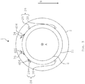
- the Fig. 2 shows another strong simplified schematic view of the transport container 1, and the Fig. 3 shows a schematic sectional view of the transport container 1 according to the section line III-III of Fig. 2 , The following is on the Fig. 1 to 3 simultaneously referred to.
- the transport container 1 can also be referred to as a helium transport container.
- the transport container 1 can also be used for other cryogenic fluids.
- the transport container 1 comprises an outer container 2.
- the outer container 2 is made of stainless steel, for example.
- the outer container 2 may have a length L2 of, for example, 10 meters.
- the outer container 2 comprises a tubular or cylindrical base portion 3 which is closed on both sides in each case by means of a cover section 4, 5, in particular by means of a first cover section 4 and a second cover section 5.
- the base portion 3 may have a circular or approximately circular geometry in cross section.
- the lid sections 4, 5 are curved.
- the cover sections 4, 5 are arched in opposite directions, so that both cover sections 4, 5 are curved outwardly with respect to the base section 3.
- the outer container 2 is fluid-tight, in particular gas-tight.
- the outer container 2 has a center or symmetry axis M1, to which the outer container 2 is constructed rotationally symmetrical.
- the transport container 1 further comprises an inner container 6 for receiving the helium He.
- the inner container 6 is in the Fig. 2 Not shown.
- the inner container 6 is also made of stainless steel, for example.
- a gas zone 7 with vaporized helium He and a liquid zone 8 with liquid helium He can be provided.
- the inner container 6 is fluid-tight, in particular gas-tight, and may comprise a blow-off valve for controlled pressure reduction.
- the inner container 6, like the outer container 2, comprises a tubular or cylindrical base portion 9 which is closed on both sides at the front by cover sections 10, 11, in particular a first cover section 10 and a second cover section 11.
- the Base section 9 may have a circular or approximately circular geometry in cross section.
- the inner container 6 is, like the outer container 2, constructed rotationally symmetrical to the axis of symmetry M1.
- the inner container 6 is completely enclosed by the outer container 2. Between the outer container 2 and the inner container 6, an evacuated gap or gap 12 is provided.
- the transport container 1 further comprises a cooling system 13 (FIG. Fig. 2 ) with a coolant tank 14.
- the intermediate space 12 is also provided between the coolant tank 14 and the outer tank 2.
- the gap 12 is evacuated, as previously mentioned.
- the intermediate space 12 envelops the inner container 6 and the coolant reservoir 14 completely.
- the coolant container 14 comprises a tubular or cylindrical base portion 15, which may be constructed rotationally symmetrical to the axis of symmetry M1.
- the base portion 15 may have a circular or approximately circular geometry in cross section.
- the base section 15 is closed at the front by a cover section 16, 17, in particular by a first cover section 16 and a second cover section 17.
- the lid portions 16, 17 may be curved. In particular, the lid portions 16, 17 are curved in the same direction.
- the coolant reservoir 14 may also have a different structure.
- the coolant reservoir 14 is arranged outside of the inner container 6, but inside the outer container 2.
- a gas zone 18 with vaporized or gaseous nitrogen GN2 and a liquid zone 19 with liquid nitrogen LN2 may be provided. Viewed in a direction of gravity g, the gas zone 18 is arranged above the liquid zone 19.
- the gaseous nitrogen GN2 may also be referred to as the gaseous phase of the nitrogen N2 or of the cryogenic fluid.
- the liquid nitrogen LN2 can also be referred to as the liquid phase of the nitrogen N2 or of the cryogenic fluid.
- the coolant container 14 Viewed in an axial direction A of the transport container 1, the coolant container 14 is arranged next to the inner container 6.
- the axial direction A is positioned parallel to or agrees with the axis of symmetry M1.
- the axial direction A may be oriented by the first lid portion 4 of the outer container 2 in the direction of the second lid portion 5 of the outer container 2.
- a gap or gap 20 is provided, which may be part of the gap 12. That is, the gap 20 is also evacuated.
- the transport container 1 further comprises a thermal shield 21 associated with the cooling system 13.
- the thermal shield 21 is arranged in the evacuated intermediate space 12 provided between the inner container 6 and the outer container 2.
- the thermal shield 21 is actively cooled or actively cooled with the aid of nitrogen N2. Active cooling in the present case is to be understood as meaning that the nitrogen N2 for the purpose of cooling the thermal shield 21 is passed through it or passed along it.
- the thermal shield 21 is hereby cooled to a temperature which corresponds approximately to the boiling point of the nitrogen N2.
- the thermal shield 21 comprises a cylinder-shaped or tubular base section 22, which is closed on both sides by a cover section 23, 24, in particular a first cover section 23 and a second cover section 24, which terminates this end face. Both the base portion 22 and the lid portions 23, 24 are actively cooled by means of the nitrogen N2.
- the base portion 22 may have a circular or approximately circular geometry in cross section.
- the thermal shield 21 is preferably also constructed rotationally symmetrical to the axis of symmetry M1.
- the second cover section 24 of the thermal shield 21 is arranged between the inner container 6, in particular the second lid section 11 of the inner container 6, and the coolant container 14, in particular the first lid section 16 of the coolant container 14.
- the thermal shield 21, in particular the second cover portion 24 of the thermal shield 21, is a separate component from the coolant reservoir 14. That is, the thermal shield 21, particularly the second lid portion 24 of the thermal shield 21, is not part of the coolant tank 14.
- the gap 12 completely envelops the thermal shield 21.
- the first cover portion 23 of the thermal shield 21 is facing away from the coolant tank 14.
- the first lid portion 23 of the thermal shield 21 is disposed between the first lid portion 4 of the outer container 2 and the first lid portion 10 of the inner container 6.
- the thermal shield 21 is self-supporting. That is, the thermal shield 21 rests neither on the inner container 6 nor on the outer container 2.
- a support ring may be provided on the thermal shield 21, which is suspended by means of support rods, in particular tension rods, on the outer container 2.
- the inner container 6 can be suspended on the support ring via further support rods, in particular tension rods.
- the heat input through the mechanical support rods is partially realized by the support ring.
- the support ring has pockets that allow the greatest possible thermal length of the support rods.
- the coolant reservoir 14 may include bushings for the mechanical support rods.
- the thermal shield 21 is fluid-permeable. That is, a gap or gap 25 between the inner container 6 and the thermal shield 21 is in fluid communication with the gap 12. In this way, the gaps 12, 25 can be evacuated simultaneously.
- the intermediate space 25 envelops the inner container 6 completely.
- This isolation element may be or include a so-called MLI (Multilayer Insulation).
- MLI Multilayer Insulation
- In the thermal shield 21 holes, openings or the like may be provided to allow simultaneous evacuation of the spaces 12, 25.
- the thermal shield 21 is preferably made of a high purity aluminum material.
- the second cover portion 24 of the thermal shield 21 completely shields the coolant reservoir 14 from the inner container 6. That is, as seen from the inner container 6 to the coolant tank 14, in particular, viewed in the axial direction A, the coolant tank 14 is completely covered or shielded by the second lid portion 24 of the thermal shield 21.
- the thermal shield 21 encloses the inner container 6 completely. That is, the inner container 6 is completely disposed within the thermal shield 21, the thermal shield 21, as previously mentioned, is not fluid-tight.
- the thermal shield 21 for actively cooling the same comprises at least one cooling line 26.
- the cooling line 26 is assigned to the cooling system 13.
- a plurality of such cooling lines 26, for example six such cooling lines 26, are provided.
- the number of cooling lines 26 is arbitrary.
- the cooling line 26 may comprise two perpendicular sections 27, 28 extending in the direction of gravity g and two inclined sections 29, 30.
- the vertical sections 27, 28 may be provided on the lid sections 23, 24 and / or on the base section 22 of the thermal shield 21.
- the oblique sections 29, 30 may also be provided on the lid sections 23, 24 and / or on the base section 22.
- the portion 27 is in fluid communication with the portion 29 and the portion 30 is in fluid communication with the portion 28.
- the cooling line 26 is connected to the thermal shield 21 both mechanically and thermally.
- the cooling line 26 can be materially connected to the thermal shield 21.
- cohesive connections the connection partners are held together by atomic or molecular forces.
- Cohesive connections are non-detachable compounds that can only be separated by destroying the connection means or the connection partners.
- Cohesive can be connected for example by gluing, soldering, welding or vulcanization.
- the cooling line 26 or the cooling lines 26 are welded to the thermal shield 21, soldered or glued.
- the cooling line 26 is in fluid communication with the coolant reservoir 14 by means of a connecting line 31, so that when the coolant reservoir 14 is filled, the nitrogen N 2 is forced from the coolant reservoir 14 into the cooling line 26.
- the connecting line 31 is part of the cooling line 26.
- the cooling line 26 may also be directly in communication with the coolant reservoir 14.
- the connection line 31 opens into a distributor 32, from which the section 27 and the section 30 of the cooling line 26 branch off.
- the distributor 32 forms a lowest point of the cooling line 26 with respect to the direction of gravity g. Therefore, the distributor 32 can also be referred to as the lowest point of the cooling line 26.
- This lowest point of the cooling line 26 is in fluid communication with the liquid zone 19 of the coolant tank 14 by means of the connecting line 31.
- connection line 31 can open into a point of the coolant container 14 which is the lowest point with respect to the direction of gravity g.
- the Section 29 and the section 28 of the cooling line 26 meet at a collector 33, which forms a highest point of the cooling line 26 with respect to the direction of gravity g. Therefore, collector 33 may also be referred to as the highest point of the cooling line 26.
- the cooling pipes 26 are provided both on the base portion 22 and on the lid portions 23, 24 of the thermal shield 21.
- the cover sections 23, 24 are integral with one another, in particular materially bonded, to the base section 22.
- the lid portions 23, 24 are welded to the base portion 22.
- the cooling line 26 and in particular the inclined sections 29, 30 of the cooling line 26 have a pitch relative to a horizontal H1, which is arranged perpendicular to the direction of gravity g and parallel to the axis of symmetry M1.
- the inclined portions 29, 30 are inclined in the direction of the coolant tank 14.
- the sections 29, 30 with the horizontal H preferably include an angle of inclination ⁇ greater than 3 °.
- the inclination angle ⁇ can be 3 ° to 15 ° or even more.
- the inclination angle ⁇ can also be exactly 3 °.
- the inclination angle ⁇ can also be referred to as the first inclination angle.
- the sections 29, 30 have a positive gradient in the direction of the collector 33, so that gas bubbles produced during the boiling of the nitrogen N 2 in the cooling line 26 ascend to the collector 33.
- a phase separator arranged outside the outer container 2 can be connected, which is set up to separate the gaseous nitrogen GN2 from the liquid nitrogen LN2 and to blow off the gaseous nitrogen GN2 into the environment. In the present case, however, dispensed with such a phase separator.
- isolation element may be arranged, which fills the gap 12.
- This insulating element is provided on the outside of the thermal shield 21 and can fill the gap 12.
- the insulation element preferably completely fills the gap 12 in the region of the inner container 6, so that there the insulation element thermal shield 21 on the outside and the outer container 2 inside contacted.
- the insulating member encloses the thermal shield 21 except for the second lid portion 24 thereof, that is, enclosing the first lid portion 23 and the base portion 22. Further, the cylindrical base portion 15 and the second lid portion 17 of the coolant tank 14 are enclosed by the insulating member.
- the isolation element is preferably also a so-called MLI or may comprise an MLI.
- the insulation element like the thermal shield 21, can be actively cooled. The active cooling takes place with the aid of the cryogenic nitrogen GN2. For active cooling of the insulation element, a further cooling line can be passed through it.
- the cooling line can be helical or helical.
- the transport container 1 comprises at least one return line 34, 35 (FIG. Fig. 3 ).
- a first return line 34 and a second return line 35 are provided.
- the number of return lines 34, 35 is arbitrary.
- the return lines 34, 35 may be provided on the outside of the thermal shield 21.
- the return lines 34, 35 are at least mechanically connected to the thermal shield 21 and preferably arranged between the thermal shield 21 and the outer container 2. Alternatively, the return lines 34, 35 may also be thermally connected to the thermal shield 21.
- the return lines 34, 35 are inclined in the direction of the coolant tank 14. In particular, the return lines 34, 35 are inclined at an inclination angle ⁇ relative to a horizontal H2.
- the horizontal H2 is arranged parallel to or coincides with the horizontal H1.
- the inclination angle ⁇ may also be referred to as the second inclination angle.
- the inclination angle ⁇ may be 4 °, for example.
- the inclination angle ⁇ may be 4 ° to 15 ° or even more. In particular, the inclination angle ⁇ can also be exactly 4 °.
- the return lines 34, 35 are preferably associated with the cooling system 13.
- the return lines 34, 35 are in fluid communication with the gas zone 18 of the coolant tank. That is, with respect to the direction of gravity g, the cooling lines 34, 35 above the cooling line 26, in particular above the connection line 31 of the cooling line 26, open into the coolant container 14.
- the accumulator 33 which is the highest point of the cooling line 26, is in fluid communication with the coolant reservoir 14 by means of the return lines 34, 35.
- the return lines 34, 35 preferably run parallel to one another.
- An inner diameter d34, d35 of the return lines 34, 35 is greater than an inner diameter d26 of the cooling line 26.
- the inner diameter d26 of the cooling line 26 is preferably greater than 10 millimeters.
- the inner diameter d26 may be 12 millimeters, for example.
- the cooling system 13 further comprises a blow-off valve 36, with the aid of which the gaseous nitrogen GN2 can be blown out of the coolant reservoir 14 in a pressure-dependent manner.
- the blow-off valve 36 is adapted to blow off the gaseous nitrogen GN2 to the environment.
- the aforementioned actively cooled isolation member disposed between the outer container 2 and the thermal shield 21 may be connected to the blow-off valve 36. Blown cryogenic nitrogen gas GN2 is then passed through the isolation element to actively cool it. The thereby heated gaseous nitrogen GN2 can then be released after passing through the cooling line of the insulation element to the environment. Due to the fact that the gaseous nitrogen GN2 is no longer cryogenic when it exits the insulation element, but is heated, undesirable icing of the exit point can be prevented.
- the thermal shield 21 Before filling the inner container 6 with helium He, the thermal shield 21 is first of all approximately at least approximately or completely up to the boiling point (1.3 bara, 7.95 K) of the liquid nitrogen LN2 with the aid of cryogenic, initially gaseous and later liquid nitrogen N2 cooled.
- the inner container 6 is not actively cooled.
- the thermal shield 21 Upon cooling of the thermal shield 21, the vacuum residual gas still remaining in the interstices 12, 20, 25 on the thermal shield 21 frozen out. As a result, it can be prevented when filling the inner container 6 with the helium He that the vacuum residual gas on the outside of the inner container 6 freezes and thus contaminated.
- the thermal shield 21 and the coolant reservoir 14 are completely cooled and the coolant reservoir 14 is again completely filled with nitrogen N 2, the inner reservoir 6 is filled with the liquid helium He.
- the transport container 1 can now be transported on a transport vehicle, such as a truck or a ship, for transporting the helium He.
- the thermal shield 21 is continuously cooled by means of the liquid nitrogen LN2.
- the liquid nitrogen LN 2 boils in the cooling line 26 or in the cooling lines 26.
- Resulting gas bubbles are supplied as gaseous nitrogen GN 2 to the highest point of the cooling system 13, namely the collector 33.
- the gas bubbles thereby entrain liquid nitrogen LN2 from the cooling line 26 or from the cooling lines 26 and thus convey it into the return lines 34, 35.
- the liquid nitrogen LN2 is entrained by the resulting gas bubbles up to a static height of about two meters. This results in no continuous, but a discontinuous promotion of the liquid nitrogen LN2.
- the liquid nitrogen LN2 is pumped like a gush or in a surge.
- the conveyed into the return lines 34, 35 liquid nitrogen LN2 and the gaseous nitrogen GN2 are supplied via the return lines 34, 35 back to the coolant tank 14.
- the liquid nitrogen LN2 partially vaporizes in the return lines 34, 35. Unevaporated portions of the liquid nitrogen LN2 fall back into the coolant tank 14. Because the return lines 34, 35 have a larger inner diameter d34, d35 than the cooling line 26, the entrained liquid nitrogen LN2 can be conveyed freely into the return lines 34, 35.
- the nitrogen N2 is from the cooling line 26 and the cooling lines 26 and the Return lines 34, 35 promoted without a moving parts having pump in a circle.
- the liquid nitrogen LN2 is conveyed only with the help of the gaseous nitrogen GN2.
- the cooling line 26 or the cooling lines 26 and the return lines 34, 35 act as a so-called bubble pump or mammoth pump, which is suitable for conveying the liquid nitrogen LN2.
- This natural circulation described above works without or at least approximately without overpressure. Therefore, the pressure in the coolant tank 14 can be reduced from the commonly required 1.3 bara to 1.1 bara. This lowering of the pressure in the coolant tank 14 leads to a lowering of the boiling temperature of the liquid nitrogen LN2 by 1.5 K.
- the heat input to the helium He is thereby reduced by about 5%, so that the helium hold time compared to an arrangement without Such return lines 34, 35 increases significantly, namely by about three days.
- phase separator for separating the liquid nitrogen LN2 of the gaseous nitrogen N2.
- a phase separator comprises movable components which are subject to wear. That is, the phase separator has a limited life.
- dispensing with a phase separator thus reduces both the cost of manufacturing and maintenance of such a transport container 1.
- the phase separator which is usually arranged on the outside of the outer container 2 as an additional component, even the same damage is excluded.
- the handling of the transport container 1 is simplified by this. Also, caused by the phase separator heat input into the cooling system 13 is not negligible. Also for this reason, the waiver of the phase separator is advantageous.
- cryogenic nitrogen gas is released only at one point, namely at the blow-off valve 36, the implementation of the active cooling of the insulation element arranged between the thermal shield 21 and the outer container 2 is simpler, since only one cooling line has to be laid.
- only heated gaseous nitrogen GN2 exits from the transport container 1, so that in addition to the drastically increased Holding time for the liquid nitrogen LIN2 also, as already mentioned, no unwanted icing on the transport container 1 may occur.
Landscapes
- Engineering & Computer Science (AREA)
- Mechanical Engineering (AREA)
- General Engineering & Computer Science (AREA)
- Physics & Mathematics (AREA)
- Thermal Sciences (AREA)
- Filling Or Discharging Of Gas Storage Vessels (AREA)
- Containers, Films, And Cooling For Superconductive Devices (AREA)
Abstract
Description
- Die Erfindung betrifft einen Transportbehälter für Helium.
- Helium wird zusammen mit Erdgas gefördert. Ein Transport großer Mengen Helium ist aus ökonomischen Gründen nur in flüssiger beziehungsweise überkritischer Form, das heißt, bei einer Temperatur von etwa 4,2 bis 6 K und unter einem Druck von 1 bis 6 bar sinnvoll. Zum Transport des flüssigen beziehungsweise überkritischen Heliums werden Transportbehälter eingesetzt, die, um einen zu schnellen Druckanstieg des Heliums zu vermeiden, aufwendig thermisch isoliert werden. Derartige Transportbehälter können beispielsweise mit Hilfe von flüssigem Stickstoff gekühlt werden. Hierbei wird ein mit dem flüssigen Stickstoff gekühlter thermischer Schild vorgesehen. Der thermische Schild schirmt einen Innenbehälter des Transportbehälters ab. In dem Innenbehälter ist das flüssige beziehungsweise tiefkalte Helium aufgenommen. Die Haltezeit für das flüssige beziehungsweise tiefkalte Helium beträgt bei derartigen Transportbehältern 35 bis 40 Tage, das heißt, nach dieser Zeit ist der Druck in dem Innenbehälter auf den Maximalwert von 6 bar gestiegen. Der Vorrat an flüssigem Stickstoff reicht für etwa 35 Tage aus.
- Vor diesem Hintergrund besteht die Aufgabe der vorliegenden Erfindung darin, einen verbesserten Transportbehälter zur Verfügung zu stellen.
- Demgemäß wird ein Transportbehälter für Helium vorgeschlagen. Der Transportbehälter umfasst einen Innenbehälter zum Aufnehmen des Heliums, einen Kühlmittelbehälter zum Aufnehmen eines kryogenen Fluids, einen Außenbehälter, in dem der Innenbehälter und der Kühlmittelbehälter aufgenommen sind, einen thermischen Schild, in dem der Innenbehälter aufgenommen ist und der mit Hilfe des kryogenen Fluids aktiv kühlbar ist, wobei der thermische Schild zumindest eine Kühlleitung aufweist, die mit dem Kühlmittelbehälter in Fluidverbindung ist und in der zum aktiven Kühlen des thermischen Schilds das kryogene Fluid aufnehmbar ist, und zumindest eine Rücklaufleitung, mit deren Hilfe die zumindest eine Kühlleitung mit dem Kühlmittelbehälter in Fluidverbindung ist, um das kryogene Fluid wieder dem Kühlmittelbehälter zuzuführen.
- Dadurch, dass die Rücklaufleitung vorgesehen ist, wird das zum Kühlen verwendete kryogene Fluid aus der Kühlleitung wieder dem Kühlmittelbehälter zugeführt. Mit Hilfe der Rücklaufleitung können insbesondere eine flüssige Phase des kryogenen Fluids, die aus der Kühlleitung des thermischen Schilds aufgrund von Blasenbildung in der Kühlleitung in die Rücklaufleitung mitgerissen wird, und eine verdampfte Phase des kryogenen Fluids wieder dem Kühlmittelbehälter zugeführt werden. Durch den Mitriss der flüssigen Phase kann sichergestellt werden, dass das kryogene Fluid stets bis zu einem höchsten Punkt der Kühlleitung in dieser steht oder in dieser vorhanden ist. Nichtverdampftes kryogenes Fluid wird in einem Umlauf, insbesondere in einem Naturumlauf, das heißt, in einem selbsttätigen Umlauf, dem Kühlmittelbehälter wieder zugeführt. Auch die gasförmige Phase wird dem Kühlmittelbehälter in diesem Umlauf wieder zugeführt.
- Auf die Verwendung eines Phasenseparators, der üblicherweise die gasförmige Phase des kryogenen Fluids von der flüssigen Phase des kryogenen Fluids trennt, kann hierdurch vollständig verzichtet werden. Dies reduziert die Kosten zum Herstellen und Warten des Transportbehälters. Ein derartiger Phasenseparator umfasst bewegliche Teile und hat daher eine begrenzte Lebensdauer. Ebenso ist der Wärmeeinfall auf ein die Kühlleitung umfassendes Kühlsystem durch einen Phasenseparator nicht unerheblich. Dieser Wärmeeinfall fällt durch den Verzicht auf den Phasenseparator weg. Ein derartiger Phasenseparator kann ferner als außenseitig an dem Transportbehälter vorgesehenes Anbauteil beim Handling des Transportbehälters beschädigt werden. Auch diese Gefahr besteht durch den Verzicht auf den Phasenseparator nicht mehr. Der Transportbehälter ist damit phasenseparatorfrei oder phasenseparatorlos.
- Der zuvor erwähnte Naturumlauf funktioniert bevorzugt ohne oder zumindest mit geringem Überdruck. Daher kann der Druck im Kühlmittelbehälter von 1,3 bara auf 1,1 bara abgesenkt werden. Diese Absenkung des Drucks führt zu einer Erniedrigung der Siedetemperatur des kryogenen Fluids, vorliegend beispielsweise Stickstoff, um 1,5 K. Der Wärmeeinfall auf das Helium verringert sich dadurch um etwa 5%, so dass die Helium-Haltezeit im Vergleich zu bekannten Transportbehältern um etwa drei Tage ansteigt.
- Der Innenbehälter kann auch als Heliumbehälter oder als Innentank bezeichnet werden. Der Transportbehälter kann auch als Helium-Transportbehälter bezeichnet werden. Das Helium kann als flüssiges oder tiefkaltes Helium bezeichnet werden. Das Helium ist insbesondere ebenfalls ein kryogenes Fluid. Der Transportbehälter ist insbesondere dazu eingerichtet, das Helium in tiefkalter oder flüssiger beziehungsweise in überkritischer Form zu transportieren. In der Thermodynamik ist der kritische Punkt ein thermodynamischer Zustand eines Stoffes, der sich durch Angleichen der Dichten von flüssiger Phase und Gasphase kennzeichnet. Die Unterschiede zwischen beiden Aggregatszuständen hören an diesem Punkt auf zu existieren. In einem Phasendiagramm stellt der kritische Punkt das obere Ende der Dampfdruckkurve dar.
- Das Helium wird in flüssiger beziehungsweise tiefkalter Form in den Innenbehälter eingefüllt. In dem Innenbehälter bildet sich dann eine Flüssigkeitszone mit flüssigem Helium und eine Gaszone mit gasförmigem Helium. Das Helium weist also nach dem Einfüllen in den Innenbehälter zwei Phasen mit unterschiedlichen Aggregatszuständen, nämlich flüssig und gasförmig, auf. Das heißt, in dem Innenbehälter befindet sich eine Phasengrenze zwischen dem flüssigen Helium und dem gasförmigen Helium. Nach einer gewissen Zeit, das heißt, dann wenn der Druck in dem Innenbehälter steigt, wird das sich in dem Innenbehälter befindende Helium einphasig. Die Phasengrenze existiert dann nicht mehr, und das Helium ist überkritisch.
- Das kryogene Fluid oder das Kryogen ist vorzugsweise flüssiger Stickstoff. Das kryogene Fluid kann auch als Kühlmittel bezeichnet werden. Das kryogene Fluid kann alternativ beispielsweise auch flüssiger Wasserstoff oder flüssiger Sauerstoff sein. Darunter, dass der thermische Schild aktiv kühlbar oder aktiv gekühlt ist, ist zu verstehen, dass der thermische Schild von dem kryogenen Fluid zumindest partiell durchströmt oder umströmt wird, um diesen zu kühlen. Dabei siedet das kryogene Fluid, und es liegt somit die gasförmige Phase sowie die flüssige Phase des kryogenen Fluids vor. In der Kühlleitung kann das kryogene Fluid daher sowohl in seiner gasförmigen als auch in seiner flüssigen Phase aufgenommen sein. Ebenso kann das kryogene Fluid in der Rücklaufleitung in seiner flüssigen Phase und/oder in seiner gasförmigen Phase aufgenommen sein beziehungsweise zurück zu dem Kühlmittelbehälter gefördert werden. In der Rücklaufleitung kann die flüssige Phase des kryogenen Fluids zumindest teilweise verdampfen. Nicht verdampfte Anteile der flüssigen Phase des kryogenen Fluids fallen zurück in den Kühlmittelbehälter. Die flüssige Phase wird insbesondere mit Hilfe der gasförmigen Phase des kryogenen Fluids gefördert. Auf eine Pumpe mit beweglichen Bauteilen kann verzichtet werden. Im Betrieb des Transportbehälters beziehungsweise des thermischen Schilds strömt beim Verdampfen des kryogenen Fluids die flüssige Phase des kryogenen Fluids aus dem Kühlmittelbehälter in die Kühlleitung nach, so dass die Kühlleitung stets über ihre gesamte Länge mit der flüssigen Phase gefüllt ist. Der Kühlmittelbehälter, die Kühlleitung und die Rücklaufleitung bilden somit ein Kühlsystem. Das Kühlsystem ist ein geschlossenes System, in dem ein Umlauf des kryogenen Fluids möglich ist.
- Insbesondere ist der thermische Schild nur im Betrieb des Transportbehälters, das heißt dann, wenn der Innenbehälter mit Helium gefüllt ist, aktiv gekühlt. Wenn das kryogene Fluid verbraucht ist, kann der thermische Schild auch ungekühlt sein. Wie zuvor erwähnt, kann bei dem aktiven Kühlen des thermischen Schilds das kryogene Fluid in der Kühlleitung, aber auch in der Rücklaufleitung, verdampfen. Der thermische Schild weist hierdurch eine Temperatur auf, die annähernd oder genau dem Siedepunkt des kryogenen Fluids entspricht. Der Siedepunkt des kryogenen Fluids ist vorzugsweise höher als der Siedepunkt des flüssigen Heliums. Der thermische Schild ist insbesondere innerhalb des Außenbehälters angeordnet. Vorzugsweise ist der Kühlmittelbehälter außerhalb des thermischen Schilds angeordnet. Vorzugsweise sind die Kühlleitung und die Rücklaufleitung zwei voneinander getrennte Bauteile. Das heißt, die Kühlleitung entspricht nicht der Rücklaufleitung.
- Vorzugsweise weist der Innenbehälter außenseitig eine Temperatur auf, die annähernd oder genau der Temperatur des in dem Innenbehälter gespeicherten Heliums entspricht. Die Temperatur des Heliums beträgt, je nachdem, ob das Helium in flüssiger oder überkritischer Form vorliegt, 4,2 bis 6 K. Vorzugsweise schließt ein Deckelabschnitt des thermischen Schilds einen Basisabschnitt desselben jeweils stirnseitig vollständig ab. Der Basisabschnitt des thermischen Schilds kann einen kreisrunden oder einen annähernd kreisrunden Querschnitt aufweisen. Der Außenbehälter, der Innenbehälter, der Kühlmittelbehälter und der thermische Schild können rotationssymmetrisch zu einer gemeinsamen Mittel- oder Symmetrieachse aufgebaut sein. Der Innenbehälter und der Außenbehälter sind vorzugsweise aus Edelstahl gefertigt. Der Innenbehälter weist vorzugsweise einen rohrförmigen Basisabschnitt auf, der beidseits mit gewölbten Deckelabschnitten verschlossen ist.
- Der Innenbehälter ist fluiddicht. Der Außenbehälter weist vorzugsweise ebenfalls einen rohrförmigen Basisabschnitt auf, der stirnseitig beidseits von Deckelabschnitten verschlossen ist. Der Basisabschnitt des Innenbehälters und/oder der Basisabschnitt des Außenbehälters können einen kreisrunden oder einen annähernd kreisrunden Querschnitt aufweisen. Der thermische Schild ist vorzugsweise aus einem hochreinen Aluminiumwerkstoff gefertigt. Der thermische Schild ist vorzugsweise nicht fluiddicht. Das heißt, der thermische Schild kann Durchbrüche oder Bohrungen aufweisen.
- Gemäß einer Ausführungsform ist die zumindest eine Kühlleitung mit einer Flüssigkeitszone des Kühlmittelbehälters in Fluidverbindung und die zumindest eine Rücklaufleitung ist mit einer Gaszone des Kühlmittelbehälters in Fluidverbindung.
- Bezüglich einer Schwerkraftrichtung ist die Gaszone oberhalb der Flüssigkeitszone angeordnet. Zwischen der Gaszone und der Flüssigkeitszone ist eine Phasengrenze angeordnet. Beim Einfüllen des kryogenen Fluids in den Kühlmittelbehälter verdampft dieses zumindest teilweise, und die oberhalb der Flüssigkeitszone angeordnete Gaszone bildet sich aus. Die Kühlleitung mündet somit in die Flüssigkeitszone ein, und die Rücklaufleitung mündet in die Gaszone ein.
- Gemäß einer weiteren Ausführungsform mündet die zumindest eine Rücklaufleitung bezüglich einer Schwerkraftrichtung oberhalb der zumindest einen Kühlleitung in den Kühlmittelbehälter.
- Die Rücklaufleitung ist insbesondere direkt mit dem Kühlmittelbehälter verbunden. Die Kühlleitung kann über eine Anschlussleitung mit dem Kühlmittelbehälter verbunden sein. Alternativ kann die Kühlleitung auch direkt mit dem Kühlmittelbehälter verbunden sein. Die Kühlleitung kann zwei in der Schwerkraftrichtung verlaufende vertikale Abschnitte aufweisen, die mit Hilfe von bezüglich einer Horizontalen schräg angeordneten Abschnitten miteinander verbunden sind. Die Kühlleitung kann ferner einen Verteiler aufweisen, in den die zuvor erwähnte Anschlussleitung einmündet und der mit Hilfe der Anschlussleitung mit dem Kühlmittelbehälter verbunden ist. Der Verteiler stellt einen tiefsten Punkt der Kühlleitung dar. Von dem Verteiler führen dann ein vertikaler sowie ein schräger Abschnitt der Kühlleitung weg. Die vertikalen und die schrägen Abschnitte der Kühlleitung vereinen sich wieder an einem Sammler. Der Sammler stellt einen höchsten Punkt der Kühlleitung dar. An dem Sammler ist die Rücklaufleitung angeschlossen.
- Gemäß einer weiteren Ausführungsform ist ein tiefster Punkt der zumindest einen Kühlleitung mit dem Kühlmittelbehälter in Fluidverbindung.
- Der tiefste Punkt der Kühlleitung kann der zuvor erwähnte Verteiler sein, der mit Hilfe der Anschlussleitung mit dem Kühlmittelbehälter in Fluidverbindung ist. Der tiefste Punkt kann auch als Verteiler oder der Verteiler kann als tiefster Punkt der Kühlleitung bezeichnet werden.
- Gemäß einer weiteren Ausführungsform ist ein höchster Punkt der zumindest einen Kühlleitung mit Hilfe der zumindest einen Rücklaufleitung mit dem Kühlmittelbehälter in Fluidverbindung.
- Der höchste Punkt der Kühlleitung ist der zuvor erwähnte Sammler. Die Rücklaufleitung verbindet den Sammler mit dem Kühlmittelbehälter. Der höchste Punkt kann auch als Sammler oder der Sammler kann auch als höchster Punkt der Kühlleitung bezeichnet werden.
- Gemäß einer weiteren Ausführungsform ist ein Innendurchmesser der zumindest einen Rücklaufleitung größer als ein Innendurchmesser der zumindest einen Kühlleitung.
- Hierdurch wird zuverlässig verhindert, dass sich das kryogene Fluid in der Rücklaufleitung aufstaut. Vielmehr können sich in dem kryogenen Fluid bildende Gasblasen die flüssige Phase des kryogenen Fluids aus der Kühlleitung mit in die Rücklaufleitung reißen. Beispielsweise ist der Innendurchmesser der Rücklaufleitung um 10%, 20%, 30% oder 40% größer als der Innendurchmesser der Kühlleitung.
- Gemäß einer weiteren Ausführungsform ist der Innendurchmesser der zumindest einen Kühlleitung größer als 10 Millimeter.
- Beispielsweise beträgt der Innendurchmesser der Kühlleitung 12, 13, 14 oder mehr Millimeter.
- Gemäß einer weiteren Ausführungsform ist die zumindest eine Rücklaufleitung in einem Neigungswinkel in Richtung des Kühlmittelbehälters geneigt.
- Das heißt, die Rücklaufleitung fällt in Richtung des Kühlmittelbehälters ab. Hierdurch ist gewährleistet, dass die flüssige Phase des kryogenen Fluids wieder zurück in den Kühlmittelbehälter strömt. Der Neigungswinkel ist definiert als ein Neigungswinkel der Rücklaufleitung relativ zu einer Horizontalen oder zu der Symmetrieachse des Transportbehälters. Die Horizontale ist dabei parallel zu der Symmetrieachse positioniert.
- Gemäß einer weiteren Ausführungsform ist die zumindest eine Rücklaufleitung mit dem thermischen Schild verbunden und zwischen dem thermischen Schild und dem Außenbehälter angeordnet.
- Vorzugsweise verläuft die Rücklaufleitung bezüglich der Schwerkraftrichtung an einem oberen Bereich des thermischen Schilds. Die Rücklaufleitung kann thermisch und/oder mechanisch mit dem thermischen Schild gekoppelt sein. Beispielsweise kann die Rücklaufleitung mit dem thermischen Schild verklebt oder mit diesem verklammert sein. Die Rücklaufleitung kann anstatt außerhalb des thermischen Schilds auch innerhalb des thermischen Schilds angeordnet sein.
- Gemäß einer weiteren Ausführungsform siedet das kryogene Fluid im Betrieb des Transportbehälters zum aktiven Kühlen des thermischen Schilds in der zumindest einen Kühlleitung, so dass in der zumindest einen Kühlleitung entstehende Gasblasen einer gasförmigen Phase des kryogenen Fluids eine flüssige Phase des kryogenen Fluids in die zumindest eine Rücklaufleitung fördern, um die gasförmige Phase des kryogenen Fluids und/oder die flüssige Phase des kryogenen Fluids wieder dem Kühlmittelbehälter zuzuführen.
- Die Gasblasen reißen die flüssige Phase des kryogenen Fluids aus der Kühlleitung mit in die Rücklaufleitung. Es ergibt sich hierdurch jedoch keine kontinuierliche, sondern eine diskontinuierliche Förderung der flüssigen Phase des kryogenen Fluids. Die Kühlleitung und die Rücklaufleitung bilden somit eine Pumpeinrichtung in Form einer Blasenpumpe oder Mammutpumpe, die dazu geeignet ist, das kryogene Fluid aus dem Kühlmittelbehälter durch die Kühlleitung und von der Kühlleitung über die Rücklaufleitung wieder dem Kühlmittelbehälter zuzuführen.
- Gemäß einer weiteren Ausführungsform sind eine erste Rücklaufleitung und eine zweite Rücklaufleitung vorgesehen, die parallel zueinander verlaufen.
- Die Rücklaufleitungen können auch voneinander weg verlaufen. Die Anzahl der Rücklaufleitungen ist beliebig. Zumindest ist jedoch eine Rücklaufleitung vorgesehen.
- Gemäß einer weiteren Ausführungsform weist der Kühlmittelbehälter ein Abblasventil zum Abblasen einer gasförmigen Phase des kryogenen Fluids aus dem Kühlmittelbehälter auf.
- Hierdurch wird der Druck in dem Kühlmittelbehälter reguliert. Die abgeblasene gasförmige Phase des kryogenen Fluids kann einem zwischen dem thermischen Schild und dem Außenbehälter angeordneten, aktiv kühlbaren Isolationselement zugeführt werden. Nach dem Durchlauf der gasförmigen Phase des kryogenen Fluids durch dieses Isolationselement ist die gasförmige Phase nicht mehr tiefkalt und kann als erwärmte gasförmige Phase an die Umgebung abgegeben werden, ohne dass es zu einer unerwünschten Vereisung an dem Transportbehälter kommen kann.
- Gemäß einer weiteren Ausführungsform ist der Innenbehälter vollständig von dem thermischen Schild umgeben.
- Das heißt, der thermische Schild hüllt den Innenbehälter vollständig ein. Der thermische Schild ist dabei vorzugsweise nicht fluiddicht.
- Gemäß einer weiteren Ausführungsform weist der thermische Schild einen von dem Kühlmittelbehälter getrennten Deckelabschnitt auf, der zwischen dem Innenbehälter und dem Kühlmittelbehälter angeordnet ist.
- Vorzugsweise weist der thermische Schild den rohrförmigen Basisabschnitt auf, der beidseitig von den Deckelabschnitten verschlossen ist. Zwischen dem Innenbehälter und dem Kühlmittelbehälter ist einer der Deckelabschnitte des thermischen Schilds angeordnet. Der Deckelabschnitt des thermischen Schilds ist insbesondere in einem zwischen dem Innenbehälter und dem Kühlmittelbehälter vorgesehenen Zwischenraum positioniert.
- Gemäß einer weiteren Ausführungsform ist der Kühlmittelbehälter außerhalb des thermischen Schilds angeordnet.
- Vorzugsweise ist der Kühlmittelbehälter in einer Axialrichtung des Transportbehälters neben dem thermischen Schild positioniert. Zwischen dem Kühlmittelbehälter und dem thermischen Schild ist ein Zwischenraum vorgesehen. Der Kühlmittelbehälter ist vorzugsweise nicht Teil des thermischen Schilds.
- Weitere mögliche Implementierungen des Transportbehälters umfassen auch nicht explizit genannte Kombinationen von zuvor oder im Folgenden bezüglich der Ausführungsbeispiele beschriebenen Merkmalen oder Ausführungsformen. Dabei wird der Fachmann auch Einzelaspekte als Verbesserungen oder Ergänzungen zu der jeweiligen Grundform des Transportbehälters hinzufügen.
- Weitere vorteilhafte Ausgestaltungen des Transportbehälters sind Gegenstand der Unteransprüche sowie der im Folgenden beschriebenen Ausführungsbeispiele des Transportbehälters. Im Weiteren wird der Transportbehälter anhand von bevorzugten Ausführungsformen unter Bezugnahme auf die beigelegten Figuren näher erläutert.
-
Fig. 1 zeigt eine schematische Ansicht einer Ausführungsform eines Transportbehälters; -
Fig. 2 zeigt eine weitere schematische Ansicht des Transportbehälters gemäßFig. 1 ; und -
Fig. 3 zeigt eine schematische Schnittansicht des Transportbehälters gemäß der Schnittlinie III-III derFig. 2 . - In den Figuren sind gleiche oder funktionsgleiche Elemente mit denselben Bezugszeichen versehen worden, sofern nichts anderes angegeben ist. Die
Fig. 1 zeigt eine stark vereinfachte schematische Ansicht einer Ausführungsform eines Transportbehälters 1 für flüssiges Helium He. DieFig. 2 zeigt eine weitere stark vereinfachte schematische Ansicht des Transportbehälters 1, und dieFig. 3 zeigt eine schematische Schnittansicht des Transportbehälters 1 gemäß der Schnittlinie III-III derFig. 2 . Im Folgenden wird auf dieFig. 1 bis 3 gleichzeitig Bezug genommen. - Der Transportbehälter 1 kann auch als Helium-Transportbehälter bezeichnet werden. Der Transportbehälter 1 kann auch für andere kryogene Fluide eingesetzt werden. Beispiele für kryogene Fluide, oder kurz Kryogene, sind das zuvor erwähnte flüssige Helium He (Siedepunkt bei 1 bara: 4,222 K = -268,929 °C), flüssiger Wasserstoff H2 (Siedepunkt bei 1 bara: 20,268 K = -252,882 °C), flüssiger Stickstoff N2 (Siedepunkt bei 1 bara: 7,35 K = 195,80 °C) oder flüssiger Sauerstoff 02 (Siedepunkt bei 1 bara: 9,18 K = 182,97 °C).
- Der Transportbehälter 1 umfasst einen Außenbehälter 2. Der Außenbehälter 2 ist beispielsweise aus Edelstahl gefertigt. Der Außenbehälter 2 kann eine Länge L2 von beispielsweise 10 Meter aufweisen. Der Außenbehälter 2 umfasst einen rohr- oder zylinderförmigen Basisabschnitt 3, der stirnseitig beidseits jeweils mit Hilfe eines Deckelabschnitts 4, 5, insbesondere mit Hilfe eines ersten Deckelabschnitts 4 und eines zweiten Deckelabschnitts 5, verschlossen ist. Der Basisabschnitt 3 kann im Querschnitt eine kreisrunde oder annähernd kreisrunde Geometrie aufweisen. Die Deckelabschnitte 4, 5 sind gewölbt. Die Deckelabschnitte 4, 5 sind gegensinnig gewölbt, so dass beide Deckelabschnitte 4, 5 bezüglich des Basisabschnitts 3 nach außen gewölbt sind. Der Außenbehälter 2 ist fluiddicht, insbesondere gasdicht. Der Außenbehälter 2 weist eine Mittel- oder Symmetrieachse M1 auf, zu der der Außenbehälter 2 rotationssymmetrisch aufgebaut ist.
- Der Transportbehälter 1 umfasst weiterhin einen Innenbehälter 6 zum Aufnehmen des Heliums He. Der Innenbehälter 6 ist in der
Fig. 2 nicht gezeigt. Der Innenbehälter 6 ist beispielsweise ebenfalls aus Edelstahl gefertigt. In dem Innenbehälter 6 können, solange sich das Helium He im Zweiphasengebiet befindet, eine Gaszone 7 mit verdampftem Helium He und eine Flüssigkeitszone 8 mit flüssigem Helium He vorgesehen sein. Der Innenbehälter 6 ist fluiddicht, insbesondere gasdicht, und kann ein Abblasventil zum gesteuerten Druckabbau umfassen. Der Innenbehälter 6 umfasst wie der Außenbehälter 2 einen rohr- oder zylinderförmigen Basisabschnitt 9, der beidseitig stirnseits von Deckelabschnitten 10, 11, insbesondere einem ersten Deckelabschnitt 10 und einem zweiten Deckelabschnitt 11, verschlossen ist. Der Basisabschnitt 9 kann im Querschnitt eine kreisrunde oder annähernd kreisrunde Geometrie aufweisen. Der Innenbehälter 6 ist, wie der Außenbehälter 2, rotationssymmetrisch zu der Symmetrieachse M1 aufgebaut. Der Innenbehälter 6 ist vollständig von dem Außenbehälter 2 umschlossen. Zwischen dem Außenbehälter 2 und dem Innenbehälter 6 ist ein evakuierter Spalt oder Zwischenraum 12 vorgesehen. - Der Transportbehälter 1 umfasst weiterhin ein Kühlsystem 13 (
Fig. 2 ) mit einem Kühlmittelbehälter 14. Der Zwischenraum 12 ist auch zwischen dem Kühlmittelbehälter 14 und dem Außenbehälter 2 vorgesehen. Der Zwischenraum 12 ist, wie zuvor erwähnt, evakuiert. Der Zwischenraum 12 hüllt den Innenbehälter 6 und den Kühlmittelbehälter 14 vollständig ein. - In dem Kühlmittelbehälter 14 ist ein kryogenes Fluid, wie beispielsweise Stickstoff N2, aufgenommen. Nachfolgend wird das kryogene Fluid daher als Stickstoff N2 bezeichnet. Der Kühlmittelbehälter 14 umfasst einen rohr- oder zylinderförmigen Basisabschnitt 15, der rotationssymmetrisch zu der Symmetrieachse M1 aufgebaut sein kann. Der Basisabschnitt 15 kann im Querschnitt eine kreisrunde oder annähernd kreisrunde Geometrie aufweisen. Der Basisabschnitt 15 ist stirnseitig jeweils durch einen Deckelabschnitt 16, 17, insbesondere durch einen ersten Deckelabschnitt 16 und einen zweiten Deckelabschnitt 17, verschlossen. Die Deckelabschnitte 16, 17 können gewölbt sein. Insbesondere sind die Deckelabschnitte 16, 17 in die gleiche Richtung gewölbt. Der Kühlmittelbehälter 14 kann auch einen abweichenden Aufbau haben. Der Kühlmittelbehälter 14 ist außerhalb des Innenbehälters 6, jedoch innerhalb des Außenbehälters 2 angeordnet.
- In dem Kühlmittelbehälter 14 kann eine Gaszone 18 mit verdampftem oder gasförmigem Stickstoff GN2 und eine Flüssigkeitszone 19 mit flüssigem Stickstoff LN2 vorgesehen sein. In einer Schwerkraftrichtung g betrachtet ist die Gaszone 18 oberhalb der Flüssigkeitszone 19 angeordnet. Der gasförmige Stickstoff GN2 kann auch als gasförmige Phase des Stickstoffs N2 beziehungsweise des kryogenen Fluids bezeichnet werden. Der flüssige Stickstoff LN2 kann auch als flüssige Phase des Stickstoffs N2 beziehungsweise des kryogenen Fluids bezeichnet werden. In einer Axialrichtung A des Transportbehälters 1 betrachtet ist der Kühlmittelbehälter 14 neben dem Innenbehälter 6 angeordnet. Die Axialrichtung A ist parallel zu der Symmetrieachse M1 positioniert oder stimmt mit dieser überein. Die Axialrichtung A kann von dem ersten Deckelabschnitt 4 des Außenbehälters 2 in Richtung des zweiten Deckelabschnitts 5 des Außenbehälters 2 orientiert sein. Zwischen dem Innenbehälter 6, insbesondere zwischen dem zweiten Deckelabschnitt 11 des Innenbehälters 6, und dem Kühlmittelbehälter 14, insbesondere dem ersten Deckelabschnitt 16 des Kühlmittelbehälters 14, ist ein Spalt oder Zwischenraum 20 vorgesehen, der Teil des Zwischenraums 12 sein kann. Das heißt, der Zwischenraum 20 ist ebenfalls evakuiert.
- Der Transportbehälter 1 umfasst weiterhin einen dem Kühlsystem 13 zugeordneten thermischen Schild 21. Der thermische Schild 21 ist in dem zwischen dem Innenbehälter 6 und dem Außenbehälter 2 vorgesehenen evakuierten Zwischenraum 12 angeordnet. Der thermische Schild 21 ist mit Hilfe des Stickstoffs N2 aktiv kühlbar oder aktiv gekühlt. Unter einer aktiven Kühlung ist vorliegend zu verstehen, dass der Stickstoff N2 zur Kühlung des thermischen Schilds 21 durch diesen hindurchgeleitet oder an diesem entlang geleitet wird. Der thermische Schild 21 wird hierbei auf eine Temperatur abgekühlt, die etwa dem Siedepunkt des Stickstoffs N2 entspricht.
- Der thermische Schild 21 umfasst einen zylinder- oder rohrförmigen Basisabschnitt 22, der beidseitig von einem diesen stirnseitig abschließenden Deckelabschnitt 23, 24, insbesondere einem ersten Deckelabschnitt 23 und einem zweiten Deckelabschnitt 24, abgeschlossen ist. Sowohl der Basisabschnitt 22 als auch die Deckelabschnitte 23, 24 sind mit Hilfe des Stickstoffs N2 aktiv gekühlt. Der Basisabschnitt 22 kann im Querschnitt eine kreisrunde oder annähernd kreisrunde Geometrie aufweisen. Der thermische Schild 21 ist vorzugsweise ebenfalls rotationssymmetrisch zu der Symmetrieachse M1 aufgebaut.
- In der Axialrichtung A betrachtet ist der zweite Deckelabschnitt 24 des thermischen Schilds 21 zwischen dem Innenbehälter 6, insbesondere dem zweiten Deckelabschnitt 11 des Innenbehälters 6, und dem Kühlmittelbehälter 14, insbesondere dem ersten Deckelabschnitt 16 des Kühlmittelbehälters 14, angeordnet. Der thermische Schild 21, insbesondere der zweite Deckelabschnitt 24 des thermischen Schilds 21, ist ein von dem Kühlmittelbehälter 14 getrenntes Bauteil. Das heißt, der thermische Schild 21, insbesondere der zweite Deckelabschnitt 24 des thermischen Schilds 21, ist nicht Teil des Kühlmittelbehälters 14. Der Zwischenraum 12 hüllt den thermischen Schild 21 vollständig ein.
- Der erste Deckelabschnitt 23 des thermischen Schilds 21 ist dem Kühlmittelbehälter 14 abgewandt. Der erste Deckelabschnitt 23 des thermischen Schilds 21 ist zwischen dem ersten Deckelabschnitt 4 des Außenbehälters 2 und dem ersten Deckelabschnitt 10 des Innenbehälters 6 angeordnet. Der thermische Schild 21 ist dabei selbsttragend. Das heißt, der thermische Schild 21 stützt sich weder auf dem Innenbehälter 6 noch auf dem Außenbehälter 2 auf. Hierzu kann an dem thermischen Schild 21 ein Tragring vorgesehen sein, der über Abstützungsstäbe, insbesondere Zugstäbe, an dem Außenbehälter 2 abgehängt ist. Weiterhin kann der Innenbehälter 6 über weitere Abstützungsstäbe, insbesondere Zugstäbe, an dem Tragring abgehängt sein. Der Wärmeeinfall durch die mechanischen Abstützungsstäbe wird teilweise durch den Tragring realisiert. Der Tragring besitzt Taschen, die eine größtmögliche thermische Länge der Abstützungsstäbe ermöglichen. Der Kühlmittelbehälter 14 kann Durchführungen für die mechanischen Abstützungsstäbe umfassen.
- Der thermische Schild 21 ist fluiddurchlässig. Das heißt, ein Spalt oder Zwischenraum 25 zwischen dem Innenbehälter 6 und dem thermischen Schild 21 ist in Fluidverbindung mit dem Zwischenraum 12. Hierdurch können die Zwischenräume 12, 25 gleichzeitig evakuiert werden. Der Zwischenraum 25 hüllt den Innenbehälter 6 vollständig ein. In dem Zwischenraum 25 kann ein, in den
Fig. 1 bis 3 nicht gezeigtes, Isolationselement angeordnet sein. Dieses Isolationselement kann eine sogenannte MLI (engl.: Multilayer Insulation) sein oder umfassen. In dem thermischen Schild 21 können Bohrungen, Durchbrüche oder dergleichen vorgesehen sein, um ein gleichzeitiges Evakuieren der Zwischenräume 12, 25 zu ermöglichen. Der thermische Schild 21 ist vorzugsweise aus einem hochreinen Aluminiumwerkstoff gefertigt. - Der zweite Deckelabschnitt 24 des thermischen Schilds 21 schirmt den Kühlmittelbehälter 14 vollständig gegenüber dem Innenbehälter 6 ab. Das heißt, mit Blickrichtung von dem Innenbehälter 6 auf den Kühlmittelbehälter 14, insbesondere mit Blickrichtung in der Axialrichtung A, ist der Kühlmittelbehälter 14 vollständig von dem zweiten Deckelabschnitt 24 des thermischen Schilds 21 abgedeckt oder abgeschirmt. Insbesondere umschließt der thermische Schild 21 den Innenbehälter 6 dabei vollständig. Das heißt, der Innenbehälter 6 ist vollständig innerhalb des thermischen Schilds 21 angeordnet, wobei der thermische Schild 21, wie zuvor schon erwähnt, nicht fluiddicht ist.
- Wie die
Fig. 2 , in der der Innenbehälter 6 nicht gezeigt ist, weiterhin zeigt, umfasst der thermische Schild 21 zum aktiven Kühlen desselben zumindest eine Kühlleitung 26. Die Kühlleitung 26 ist dem Kühlsystem 13 zugeordnet. Vorzugsweise sind mehrere derartige Kühlleitungen 26, beispielsweise sechs derartige Kühlleitungen 26, vorgesehen. Die Anzahl der Kühlleitungen 26 ist jedoch beliebig. Die Kühlleitung 26 kann zwei in der Schwerkraftrichtung g verlaufende, senkrechte Abschnitte 27, 28 sowie zwei schräge Abschnitte 29, 30 umfassen. Die senkrechten Abschnitte 27, 28 können an den Deckelabschnitten 23, 24 und/oder an dem Basisabschnitt 22 des thermischen Schilds 21 vorgesehen sein. Die schrägen Abschnitte 29, 30 können ebenfalls an den Deckelabschnitten 23, 24 und/oder an dem Basisabschnitt 22 vorgesehen sein. Der Abschnitt 27 ist mit dem Abschnitt 29 in Fluidverbindung und der Abschnitt 30 ist mit dem Abschnitt 28 in Fluidverbindung. - Die Kühlleitung 26 ist sowohl mechanisch als auch thermisch mit dem thermischen Schild 21 verbunden. Hierzu kann die Kühlleitung 26 stoffschlüssig mit dem thermischen Schild 21 verbunden sein. Bei stoffschlüssigen Verbindungen werden die Verbindungspartner durch atomare oder molekulare Kräfte zusammengehalten. Stoffschlüssige Verbindungen sind nicht lösbare Verbindungen, die sich nur durch Zerstörung der Verbindungsmittel oder der Verbindungspartner trennen lassen. Stoffschlüssig kann beispielsweise durch Kleben, Löten, Schweißen oder Vulkanisieren verbunden werden. Vorzugsweise ist die Kühlleitung 26 beziehungsweise sind die Kühlleitungen 26 mit dem thermischen Schild 21 verschweißt, verlötet oder verklebt.
- Die Kühlleitung 26 ist mit Hilfe einer Anschlussleitung 31 mit dem Kühlmittelbehälter 14 in Fluidverbindung, so dass bei gefülltem Kühlmittelbehälter 14 der Stickstoff N2 von dem Kühlmittelbehälter 14 in die Kühlleitung 26 gedrückt wird. Die Anschlussleitung 31 ist Teil der Kühlleitung 26. Die Kühlleitung 26 kann auch direkt mit dem Kühlmittelbehälter 14 in Verbindung sein. Die Anschlussleitung 31 mündet in einen Verteiler 32, von dem der Abschnitt 27 und der Abschnitt 30 der Kühlleitung 26 abzweigen. Der Verteiler 32 bildet bezüglich der Schwerkraftrichtung g einen tiefsten Punkt der Kühlleitung 26. Daher kann der Verteiler 32 auch als tiefster Punkt der Kühlleitung 26 bezeichnet werden. Dieser tiefste Punkt der Kühlleitung 26 ist mit Hilfe der Anschlussleitung 31 mit der Flüssigkeitszone 19 des Kühlmittelbehälters 14 in Fluidverbindung. Die Anschlussleitung 31 kann dabei in einen bezüglich der Schwerkraftrichtung g tiefsten Punkt des Kühlmittelbehälters 14 einmünden. Der Abschnitt 29 und der Abschnitt 28 der Kühlleitung 26 treffen sich an einem Sammler 33, der bezüglich der Schwerkraftrichtung g einen höchsten Punkt der Kühlleitung 26 bildet. Daher kann Sammler 33 auch als höchster Punkt der Kühlleitung 26 bezeichnet werden.
- Wie zuvor erwähnt, sind die Kühlleitungen 26 sowohl an dem Basisabschnitt 22 als auch an den Deckelabschnitten 23, 24 des thermischen Schilds 21 vorgesehen. Alternativ sind die Deckelabschnitte 23, 24 materialeinteilig, insbesondere stoffschlüssig, mit dem Basisabschnitt 22 verbunden. Beispielsweise sind die Deckelabschnitte 23, 24 mit dem Basisabschnitt 22 verschweißt. Dadurch, dass die Deckelabschnitte 23, 24 materialeinteilig, das heißt, stoffschlüssig, mit dem Basisabschnitt 22 verbunden sind, kann die Kühlung der Deckelabschnitte 23, 24 auch durch Wärmeleitung erfolgen.
- Die Kühlleitung 26 und insbesondere die schrägen Abschnitte 29, 30 der Kühlleitung 26 weisen gegenüber einer Horizontalen H1, die senkrecht zu der Schwerkraftrichtung g und parallel zu der Symmetrieachse M1 angeordnet ist, eine Steigung auf. Insbesondere sind die schrägen Abschnitte 29, 30 in Richtung des Kühlmittelbehälters 14 geneigt. Bevorzugt schließen die Abschnitte 29, 30 mit der Horizontalen H einen Neigungswinkel α von größer als 3° ein. Der Neigungswinkel α kann 3° bis 15° oder auch mehr betragen. Insbesondere kann der Neigungswinkel α auch genau 3° betragen. Der Neigungswinkel α kann auch als erster Neigungswinkel bezeichnet werden. Insbesondere weisen die Abschnitte 29, 30 in Richtung des Sammlers 33 eine positive Steigung auf, so dass beim Sieden des Stickstoffs N2 in der Kühlleitung 26 entstehende Gasblasen zu dem Sammler 33 hinaufsteigen. An den Sammler 33 kann ein außerhalb des Außenbehälters 2 angeordneter Phasenseparator angeschlossen sein, der dazu eingerichtet ist, den gasförmigen Stickstoff GN2 von dem flüssigen Stickstoff LN2 zu separieren und den gasförmigen Stickstoff GN2 in die Umgebung abzublasen. Vorliegend wird jedoch auf einen derartigen Phasenseparator verzichtet.
- In dem Zwischenraum 12 kann ein in den
Fig. 1 bis 3 nicht gezeigtes Isolationselement angeordnet sein, welches den Zwischenraum 12 ausfüllt. Dieses Isolationselement ist außenseitig an dem thermischen Schild 21 vorgesehen und kann den Zwischenraum 12 ausfüllen. Das Isolationselement füllt vorzugsweise den Zwischenraum 12 im Bereich des Innenbehälters 6 vollständig aus, so dass dort das Isolationselement den thermischen Schild 21 außenseitig und den Außenbehälter 2 innenseitig kontaktiert. Das Isolationselement umschließt den thermischen Schild 21 bis auf dessen zweiten Deckelabschnitt 24, das heißt, es umschließt den ersten Deckelabschnitt 23 und den Basisabschnitt 22. Ferner wird der zylindrische Basisabschnitt 15 und der zweite Deckelabschnitt 17 des Kühlmittelbehälters 14 von dem Isolationselement umschlossen. Das Isolationselement ist vorzugsweise ebenfalls eine sogenannte MLI oder kann eine MLI umfassen. Das Isolationselement kann wie der thermische Schild 21 aktiv gekühlt sein. Die aktive Kühlung erfolgt dabei mit Hilfe des tiefkalten gasförmigen Stickstoffs GN2. Zum aktiven Kühlen des Isolationselements kann eine weitere Kühlleitung durch dieses hindurchgeführt sein. Die Kühlleitung kann wendel- oder schraubenförmig sein. - Weiterhin umfasst der Transportbehälter 1 zumindest eine Rücklaufleitung 34, 35 (
Fig. 3 ). Vorzugsweise sind eine erste Rücklaufleitung 34 und eine zweite Rücklaufleitung 35 vorgesehen. Die Anzahl der Rücklaufleitungen 34, 35 ist jedoch beliebig. Mit Hilfe der Rücklaufleitungen 34, 35 ist die Kühlleitung 26 beziehungsweise sind die Kühlleitungen 26 mit dem Kühlmittelbehälter 14 in Fluidverbindung, um den Stickstoff N2 nach dem Durchlauf durch die Kühlleitung 26 beziehungsweise die Kühlleitungen 26 wieder dem Kühlmittelbehälter 14 zuzuführen. Die Rücklaufleitungen 34, 35 können außenseitig an dem thermischen Schild 21 vorgesehen sein. Die Rücklaufleitungen 34, 35 sind mit dem thermischen Schild 21 zumindest mechanisch verbunden und bevorzugt zwischen dem thermischen Schild 21 und dem Außenbehälter 2 angeordnet. Alternativ können die Rücklaufleitungen 34, 35 auch thermisch mit dem thermischen Schild 21 verbunden sein. - Die Rücklaufleitungen 34, 35 sind in Richtung des Kühlmittelbehälters 14 geneigt. Insbesondere sind die Rücklaufleitungen 34, 35 in einem Neigungswinkel β relativ zu einer Horizontalen H2 geneigt. Die Horizontale H2 ist parallel zu der Horizontalen H1 angeordnet oder stimmt mit dieser überein. Der Neigungswinkel β kann auch als zweiter Neigungswinkel bezeichnet werden. Der Neigungswinkel β kann beispielsweise 4° betragen. Der Neigungswinkel β kann 4° bis 15° oder auch mehr betragen. Insbesondere kann der Neigungswinkel β auch genau 4° betragen. Die Rücklaufleitungen 34, 35 sind vorzugsweise dem Kühlsystem 13 zugeordnet.
- Anders als die Kühlleitung 26 beziehungsweise die Kühlleitungen 26, die mit der Flüssigkeitszone 19 des Kühlmittelbehälters 14 in Fluidverbindung sind, sind die Rücklaufleitungen 34, 35 mit der Gaszone 18 des Kühlmittelbehälters in Fluidverbindung. Das heißt, bezüglich der Schwerkraftrichtung g münden die Kühlleitungen 34, 35 oberhalb der Kühlleitung 26, insbesondere oberhalb der Anschlussleitung 31 der Kühlleitung 26, in den Kühlmittelbehälter 14 hinein. Der Sammler 33, der den höchsten Punkt der Kühlleitung 26 darstellt, ist mit Hilfe der Rücklaufleitungen 34, 35 mit dem Kühlmittelbehälter 14 in Fluidverbindung. Hierzu kann beispielsweise beidseits des thermischen Schilds 21 ein derartiger Sammler 33 vorgesehen sein. Die Rücklaufleitungen 34, 35 verlaufen vorzugsweise parallel zueinander. Ein Innendurchmesser d34, d35 der Rücklaufleitungen 34, 35 ist dabei größer als ein Innendurchmesser d26 der Kühlleitung 26. Dabei ist der Innendurchmesser d26 der Kühlleitung 26 vorzugsweise größer als 10 Millimeter. Der Innendurchmesser d26 kann beispielsweise 12 Millimeter betragen.
- Das Kühlsystem 13 umfasst weiterhin ein Abblasventil 36, mit dessen Hilfe der gasförmige Stickstoff GN2 aus dem Kühlmittelbehälter 14 druckabhängig abgeblasen werden kann. Das Abblasventil 36 ist geeignet, den gasförmigen Stickstoff GN2 an die Umgebung abzublasen. Alternativ kann das zuvor erwähnte aktiv gekühlte Isolationselement, das zwischen dem Außenbehälter 2 und dem thermischen Schild 21 angeordnet ist, an das Abblasventil 36 angeschlossen sein. Abgeblasener tiefkalter gasförmiger Stickstoff GN2 wird dann durch das Isolationselement hindurchgeführt, um dieses aktiv zu kühlen. Der dabei erwärmte gasförmige Stickstoff GN2 kann dann nach dem Durchlauf durch die Kühlleitung des Isolationselements an die Umgebung abgegeben werden. Dadurch, dass der gasförmige Stickstoff GN2 dann bei dem Austritt aus dem Isolationselement nicht mehr tiefkalt, sondern erwärmt ist, kann eine unerwünschte Vereisung der Austrittsstelle verhindert werden.
- Die Funktionsweise des Transportbehälters 1 wird im Folgenden erläutert. Vor dem Befüllen des Innenbehälters 6 mit Helium He wird zunächst der thermische Schild 21 mit Hilfe von tiefkaltem, anfangs gasförmigem und später flüssigem Stickstoff N2 zumindest annähernd oder ganz bis auf den Siedepunkt (1,3 bara, 7,95 K) des flüssigen Stickstoffs LN2 abgekühlt. Der Innenbehälter 6 wird dabei noch nicht aktiv gekühlt. Bei dem Abkühlen des thermischen Schilds 21 wird das sich noch in den Zwischenräumen 12, 20, 25 befindende Vakuum-Restgas an dem thermischen Schild 21 ausgefroren. Hierdurch kann bei einem Befüllen des Innenbehälters 6 mit dem Helium He verhindert werden, dass das Vakuum-Restgas außenseitig auf dem Innenbehälter 6 ausfriert und somit diesen verunreinigt. Sobald der thermische Schild 21 und der Kühlmittelbehälter 14 vollständig abgekühlt sind und der Kühlmittelbehälter 14 wieder vollständig mit Stickstoff N2 aufgefüllt ist, wird der Innenbehälter 6 mit dem flüssigen Helium He befüllt.
- Der Transportbehälter 1 kann zum Transportieren des Heliums He nun auf ein Transportfahrzeug, wie beispielsweise einen Lastkraftwagen oder ein Schiff, verbracht werden. Hierbei wird der thermische Schild 21 kontinuierlich mit Hilfe des flüssigen Stickstoffs LN2 gekühlt. Der flüssige Stickstoff LN2 siedet dabei in der Kühlleitung 26 beziehungsweise in den Kühlleitungen 26. Dabei entstehende Gasblasen werden als gasförmiger Stickstoff GN2 dem höchsten Punkt des Kühlsystems 13, nämlich dem Sammler 33, zugeführt. Hierbei ist stets gewährleistet, dass die Kühlleitung 26 beziehungsweise die Kühlleitungen 26 über ihre gesamte Länge mit flüssigem Stickstoff LN2 beaufschlagt sind und dadurch eine etwa dem Siedepunkt des Stickstoffs N2 entsprechende Temperatur aufweisen.
- Die Gasblasen reißen dabei flüssigen Stickstoff LN2 aus der Kühlleitung 26 beziehungsweise aus den Kühlleitungen 26 mit und fördern diesen somit in die Rücklaufleitungen 34, 35. Der flüssige Stickstoff LN2 wird dabei von den entstehenden Gasblasen bis zu einer statischen Höhe von etwa zwei Meter mitgerissen. Hierdurch ergibt sich keine kontinuierliche, sondern eine diskontinuierliche Förderung des flüssigen Stickstoffs LN2. Der flüssige Stickstoff LN2 wird schwallartig oder schwallweise gefördert. Der in die Rücklaufleitungen 34, 35 geförderte flüssige Stickstoff LN2 sowie der gasförmige Stickstoff GN2 werden über die Rücklaufleitungen 34, 35 wieder dem Kühlmittelbehälter 14 zugeführt. Der flüssige Stickstoff LN2 verdampft teilweise in den Rücklaufleitungen 34, 35. Nicht verdampfte Anteile des flüssigen Stickstoffs LN2 fallen in den Kühlmittelbehälter 14 zurück. Dadurch, dass die Rücklaufleitungen 34, 35 einen größeren Innendurchmesser d34, d35 als die Kühlleitung 26 aufweisen, kann der mitgerissene flüssige Stickstoff LN2 frei in die Rücklaufleitungen 34, 35 gefördert werden.
- Es ergibt sich somit ein Naturumlauf des Stickstoffs N2. Das heißt, der Stickstoff N2 wird von der Kühlleitung 26 beziehungsweise den Kühlleitungen 26 und den Rücklaufleitungen 34, 35 ohne eine bewegliche Teile aufweisende Pumpe im Kreis gefördert. Der flüssige Stickstoff LN2 wird nur mit Hilfe des gasförmigen Stickstoffs GN2 gefördert. Die Kühlleitung 26 beziehungsweise die Kühlleitungen 26 und die Rücklaufleitungen 34, 35 wirken als sogenannte Blasenpumpe oder Mammutpumpe, die dazu geeignet ist, den flüssigen Stickstoff LN2 zu fördern. Dieser zuvor beschriebene Naturumlauf funktioniert ohne oder zumindest annähernd ohne Überdruck. Daher kann der Druck in dem Kühlmittelbehälter 14 von üblicherweise erforderlichen 1,3 bara auf 1,1 bara gesenkt werden. Diese Absenkung des Drucks in dem Kühlmittelbehälter 14 führt zu einer Erniedrigung der Siedetemperatur des flüssigen Stickstoffs LN2 um 1,5 K. Der Wärmeeinfall auf das Helium He verringert sich dadurch um etwa 5%, so dass die Helium-Haltezeit im Vergleich zu einer Anordnung ohne derartige Rücklaufleitungen 34, 35 signifikant, nämlich um etwa drei Tage, ansteigt.
- Bei dem Transportbehälter 1 kann vorteilhafterweise auf einen Phasenseparator zum Abtrennen des flüssigen Stickstoffs LN2 von dem gasförmigen Stickstoff N2 verzichtet werden. Ein derartiger Phasenseparator umfasst bewegliche Bauteile, die einem Verschleiß unterworfen sind. Das heißt, der Phasenseparator weist eine begrenzte Lebensdauer auf. Durch den Verzicht auf einen Phasenseparator reduzieren sich somit sowohl die Kosten zur Herstellung als auch zur Wartung eines derartigen Transportbehälters 1. Ferner ist durch den Verzicht auf den Phasenseparator, der üblicherweise außenseitig an dem Außenbehälter 2 als Zusatzbauteil angeordnet ist, auch eine Beschädigung desselben ausgeschlossen. Das Handling des Transportbehälters 1 vereinfacht sich hierdurch. Auch ist der durch den Phasenseparator verursachte Wärmeeinfall in das Kühlsystem 13 nicht zu vernachlässigen. Auch aus diesem Grund ist der Verzicht auf den Phasenseparator vorteilhaft.
- Da nur an einer Stelle, nämlich an dem Abblasventil 36, tiefkalter gasförmiger Stickstoff abgegeben wird ist die Umsetzung der aktiven Kühlung des zwischen dem thermischen Schild 21 und dem Außenbehälter 2 angeordneten Isolationselements einfacher, da nur eine Kühlleitung zu verlegen ist. Für den Fall, dass ein derartiges aktiv gekühltes Isolationselement vorgesehen ist, tritt aus dem Transportbehälter 1 nur erwärmter gasförmiger Stickstoff GN2 aus, so dass neben der drastisch erhöhten Haltezeit für den flüssigen Stickstoff LIN2 auch, wie zuvor schon erwähnt, keine unerwünschten Vereisungen am Transportbehälter 1 auftreten können.
- Obwohl die vorliegende Erfindung anhand von Ausführungsbeispielen beschrieben wurde, ist sie vielfältig modifizierbar.
-
- 1
- Transportbehälter
- 2
- Außenbehälter
- 3
- Basisabschnitt
- 4
- Deckelabschnitt
- 5
- Deckelabschnitt
- 6
- Innenbehälter
- 7
- Gaszone
- 8
- Flüssigkeitszone
- 9
- Basisabschnitt
- 10
- Deckelabschnitt
- 11
- Deckelabschnitt
- 12
- Zwischenraum
- 13
- Kühlsystem
- 14
- Kühlmittelbehälter
- 15
- Basisabschnitt
- 16
- Deckelabschnitt
- 17
- Deckelabschnitt
- 18
- Gaszone
- 19
- Flüssigkeitszone
- 20
- Zwischenraum
- 21
- thermischer Schild
- 22
- Basisabschnitt
- 23
- Deckelabschnitt
- 24
- Deckelabschnitt
- 25
- Zwischenraum
- 26
- Kühlleitung
- 27
- Abschnitt
- 28
- Abschnitt
- 29
- Abschnitt
- 30
- Abschnitt
- 31
- Anschlussleitung
- 32
- Verteiler
- 33
- Sammler
- 34
- Rücklaufleitung
- 35
- Rücklaufleitung
- 36
- Abblasventil
- A
- Axialrichtung
- d26
- Innendurchmesser
- d34
- Innendurchmesser
- d35
- Innendurchmesser
- g
- Schwerkraftrichtung
- GN2
- Stickstoff
- H1
- Horizontale
- H2
- Horizontale
- He
- Helium
- LN2
- Stickstoff
- L2
- Länge
- M1
- Symmetrieachse
- N2
- Stickstoff
- α
- Neigungswinkel
- β
- Neigungswinkel
Claims (15)
- Transportbehälter (1) für Helium (He), mit einem Innenbehälter (6) zum Aufnehmen des Heliums (He), einem Kühlmittelbehälter (14) zum Aufnehmen eines kryogenen Fluids (N2), einem Außenbehälter (2), in dem der Innenbehälter (6) und der Kühlmittelbehälter (14) aufgenommen sind, einem thermischen Schild (21), in dem der Innenbehälter (6) aufgenommen ist und der mit Hilfe des kryogenen Fluids (N2) aktiv kühlbar ist, wobei der thermische Schild (21) zumindest eine Kühlleitung (26) aufweist, die mit dem Kühlmittelbehälter (14) in Fluidverbindung ist und in der zum aktiven Kühlen des thermischen Schilds (21) das kryogene Fluid (N2) aufnehmbar ist, und zumindest einer Rücklaufleitung (34, 35), mit deren Hilfe die zumindest eine Kühlleitung (26) mit dem Kühlmittelbehälter (14) in Fluidverbindung ist, um das kryogene Fluid (N2) wieder dem Kühlmittelbehälter (14) zuzuführen.
- Transportbehälter nach Anspruch 1, wobei die zumindest eine Kühlleitung (26) mit einer Flüssigkeitszone (19) des Kühlmittelbehälters (14) in Fluidverbindung ist, und wobei die zumindest eine Rücklaufleitung (34, 35) mit einer Gaszone (18) des Kühlmittelbehälters (14) in Fluidverbindung ist.
- Transportbehälter nach Anspruch 1 oder 2, wobei die zumindest eine Rücklaufleitung (34, 35) bezüglich einer Schwerkraftrichtung (g) oberhalb der zumindest einen Kühlleitung (26) in den Kühlmittelbehälter (14) mündet.
- Transportbehälter nach einem der Ansprüche 1 - 3, wobei ein tiefster Punkt der zumindest einen Kühlleitung (26) mit dem Kühlmittelbehälter (14) in Fluidverbindung ist.
- Transportbehälter nach einem der Ansprüche 1 - 4, wobei ein höchster Punkt der zumindest einen Kühlleitung (26) mit Hilfe der zumindest einen Rücklaufleitung (34, 35) mit dem Kühlmittelbehälter (14) in Fluidverbindung ist.
- Transportbehälter nach einem der Ansprüche 1 - 5, wobei ein Innendurchmesser (d34, d35) der zumindest einen Rücklaufleitung (34, 35) größer als ein Innendurchmesser (d26) der zumindest einen Kühlleitung (26) ist.
- Transportbehälter nach Anspruch 6, wobei der Innendurchmesser (d26) der zumindest einen Kühlleitung (26) größer als 10 Millimeter ist.
- Transportbehälter nach einem der Ansprüche 1 - 7, wobei die zumindest eine Rücklaufleitung (34, 35) in einem Neigungswinkel (β) in Richtung des Kühlmittelbehälters (14) geneigt ist.
- Transportbehälter nach einem der Ansprüche 1 - 8, wobei die zumindest eine Rücklaufleitung (34, 35) mit dem thermischen Schild (21) verbunden und zwischen dem thermischen Schild (21) und dem Außenbehälter (2) angeordnet ist.
- Transportbehälter nach einem der Ansprüche 1 - 9, wobei das kryogene Fluid (N2) im Betrieb des Transportbehälters (1) zum aktiven Kühlen des thermischen Schilds (21) in der zumindest einen Kühlleitung (26) siedet, so dass in der zumindest einen Kühlleitung (26) entstehende Gasblasen einer gasförmigen Phase (GN2) des kryogenen Fluids (N2) eine flüssige Phase (LN2) des kryogenen Fluids (N2) in die zumindest eine Rücklaufleitung (34, 35) fördern, um die gasförmige Phase (GN2) des kryogenen Fluids (N2) und/oder die flüssige Phase (LN2) des kryogenen Fluids (N2) wieder dem Kühlmittelbehälter (14) zuzuführen.
- Transportbehälter nach einem der Ansprüche 1 - 10, wobei eine erste Rücklaufleitung (34) und eine zweite Rücklaufleitung (35) vorgesehen sind, die parallel zueinander verlaufen.
- Transportbehälter nach einem der Ansprüche 1 - 11, wobei der Kühlmittelbehälter (14) ein Abblasventil (36) zum Abblasen einer gasförmigen Phase (GN2) des kryogenen Fluids (N2) aus dem Kühlmittelbehälter (14) aufweist.
- Transportbehälter nach einem der Ansprüche 1 - 12, wobei der Innenbehälter (6) vollständig von dem thermischen Schild (21) umgeben ist.
- Transportbehälter nach Anspruch 13, wobei der thermische Schild (21) einen von dem Kühlmittelbehälter (14) getrennten Deckelabschnitt (24) aufweist, der zwischen dem Innenbehälter (6) und dem Kühlmittelbehälter (14) angeordnet ist.
- Transportbehälter nach einem der Ansprüche 1 - 14, wobei der Kühlmittelbehälter (14) außerhalb des thermischen Schilds (21) angeordnet ist.
Priority Applications (7)
| Application Number | Priority Date | Filing Date | Title |
|---|---|---|---|
| ES17020563T ES2824537T3 (es) | 2017-12-08 | 2017-12-08 | Contenedor de transporte con escudo térmico refrigerable |
| EP17020563.7A EP3495711B1 (de) | 2017-12-08 | 2017-12-08 | Transportbehälter mit kühlbarem, thermischen schild |
| PL17020563T PL3495711T3 (pl) | 2017-12-08 | 2017-12-08 | Zbiornik transportowy ze schładzaną osłoną termiczną |
| US16/770,276 US11441733B2 (en) | 2017-12-08 | 2018-12-05 | Transport container with coolable thermal shield |
| PCT/EP2018/025308 WO2019110146A1 (de) | 2017-12-08 | 2018-12-05 | Transportbehälter mit kühlbarem, thermischen schild |
| CN201880076697.7A CN111566402B (zh) | 2017-12-08 | 2018-12-05 | 具有可冷却热屏蔽件的运输容器 |
| JP2020529266A JP7258881B2 (ja) | 2017-12-08 | 2018-12-05 | 冷却可能な熱シールドを有する輸送容器 |
Applications Claiming Priority (1)
| Application Number | Priority Date | Filing Date | Title |
|---|---|---|---|
| EP17020563.7A EP3495711B1 (de) | 2017-12-08 | 2017-12-08 | Transportbehälter mit kühlbarem, thermischen schild |
Publications (2)
| Publication Number | Publication Date |
|---|---|
| EP3495711A1 true EP3495711A1 (de) | 2019-06-12 |
| EP3495711B1 EP3495711B1 (de) | 2020-07-22 |
Family
ID=60661690
Family Applications (1)
| Application Number | Title | Priority Date | Filing Date |
|---|---|---|---|
| EP17020563.7A Active EP3495711B1 (de) | 2017-12-08 | 2017-12-08 | Transportbehälter mit kühlbarem, thermischen schild |
Country Status (7)
| Country | Link |
|---|---|
| US (1) | US11441733B2 (de) |
| EP (1) | EP3495711B1 (de) |
| JP (1) | JP7258881B2 (de) |
| CN (1) | CN111566402B (de) |
| ES (1) | ES2824537T3 (de) |
| PL (1) | PL3495711T3 (de) |
| WO (1) | WO2019110146A1 (de) |
Cited By (3)
| Publication number | Priority date | Publication date | Assignee | Title |
|---|---|---|---|---|
| WO2021197668A1 (de) * | 2020-04-02 | 2021-10-07 | Linde Gmbh | Speicherbehälter für flüssigen wasserstoff mit füllstandsanzeige |
| WO2022026971A1 (en) * | 2020-07-27 | 2022-02-03 | Exxonmobil Upstream Research Company | Container systems and methods for using the same |
| WO2025045925A1 (fr) * | 2023-08-28 | 2025-03-06 | Absolut System | Procédé de remplissage d'un réservoir d'hydrogène liquide et dispositif de stockage associé |
Families Citing this family (5)
| Publication number | Priority date | Publication date | Assignee | Title |
|---|---|---|---|---|
| CN114684506B (zh) * | 2020-12-29 | 2024-05-28 | 北京航天试验技术研究所 | 一种用于储存低温液体的卧式容器 |
| DE102022209941A1 (de) * | 2022-09-21 | 2024-03-21 | Bruker Switzerland Ag | Vorrichtung zum Transfer von flüssigem Helium, mit verringerten Transfer-Verlusten |
| CN118582656B (zh) * | 2023-03-01 | 2026-01-30 | 中国科学院理化技术研究所 | 一种大容量零蒸发存储液氦罐箱 |
| CN118031096A (zh) * | 2024-01-10 | 2024-05-14 | 南通中集能源装备有限公司 | 超低温液体储罐 |
| CN118746102A (zh) * | 2024-06-27 | 2024-10-08 | 四川中科九微氢能科技有限公司 | 介质存储容器及介质存储方法 |
Citations (4)
| Publication number | Priority date | Publication date | Assignee | Title |
|---|---|---|---|---|
| US2871669A (en) * | 1956-12-05 | 1959-02-03 | Mann Douglas | Radiation shield circulation system for large liquefied gas storage containers |
| US3782128A (en) * | 1970-06-01 | 1974-01-01 | Lox Equip | Cryogenic storage vessel |
| US4718239A (en) * | 1987-03-05 | 1988-01-12 | Union Carbide Corporation | Cryogenic storage vessel |
| WO2017190849A1 (de) * | 2016-05-04 | 2017-11-09 | Linde Aktiengesellschaft | Transportbehälter |
Family Cites Families (5)
| Publication number | Priority date | Publication date | Assignee | Title |
|---|---|---|---|---|
| JPS57154593A (en) * | 1981-03-20 | 1982-09-24 | Toshiba Corp | Ultra low temperature vessel |
| US5005362A (en) * | 1990-03-20 | 1991-04-09 | The Boc Group, Inc. | Cryogenic storage container |
| CN103234112A (zh) * | 2013-04-26 | 2013-08-07 | 北京航空航天大学 | 一种移动式低温液化燃气存储系统 |
| CN106015921B (zh) | 2016-07-07 | 2018-05-15 | 张家港富瑞氢能装备有限公司 | 一种用于储存低温液体的立式容器 |
| DE102016218000B3 (de) * | 2016-09-20 | 2017-10-05 | Bruker Biospin Gmbh | Kryostatenanordnung mit einem Vakuumbehälter und einem zu kühlenden Objekt, mit evakuierbarem Hohlraum |
-
2017
- 2017-12-08 EP EP17020563.7A patent/EP3495711B1/de active Active
- 2017-12-08 ES ES17020563T patent/ES2824537T3/es active Active
- 2017-12-08 PL PL17020563T patent/PL3495711T3/pl unknown
-
2018
- 2018-12-05 JP JP2020529266A patent/JP7258881B2/ja active Active
- 2018-12-05 CN CN201880076697.7A patent/CN111566402B/zh active Active
- 2018-12-05 WO PCT/EP2018/025308 patent/WO2019110146A1/de not_active Ceased
- 2018-12-05 US US16/770,276 patent/US11441733B2/en active Active
Patent Citations (4)
| Publication number | Priority date | Publication date | Assignee | Title |
|---|---|---|---|---|
| US2871669A (en) * | 1956-12-05 | 1959-02-03 | Mann Douglas | Radiation shield circulation system for large liquefied gas storage containers |
| US3782128A (en) * | 1970-06-01 | 1974-01-01 | Lox Equip | Cryogenic storage vessel |
| US4718239A (en) * | 1987-03-05 | 1988-01-12 | Union Carbide Corporation | Cryogenic storage vessel |
| WO2017190849A1 (de) * | 2016-05-04 | 2017-11-09 | Linde Aktiengesellschaft | Transportbehälter |
Cited By (5)
| Publication number | Priority date | Publication date | Assignee | Title |
|---|---|---|---|---|
| WO2021197668A1 (de) * | 2020-04-02 | 2021-10-07 | Linde Gmbh | Speicherbehälter für flüssigen wasserstoff mit füllstandsanzeige |
| US12320472B2 (en) | 2020-04-02 | 2025-06-03 | Linde Gmbh | Storage tank for liquid hydrogen with fill level indicator |
| WO2022026971A1 (en) * | 2020-07-27 | 2022-02-03 | Exxonmobil Upstream Research Company | Container systems and methods for using the same |
| WO2025045925A1 (fr) * | 2023-08-28 | 2025-03-06 | Absolut System | Procédé de remplissage d'un réservoir d'hydrogène liquide et dispositif de stockage associé |
| FR3152565A1 (fr) * | 2023-08-28 | 2025-03-07 | Absolut System | Dispositif de stockage d’hydrogène liquide |
Also Published As
| Publication number | Publication date |
|---|---|
| JP2021505818A (ja) | 2021-02-18 |
| PL3495711T3 (pl) | 2021-01-11 |
| WO2019110146A8 (de) | 2020-06-25 |
| EP3495711B1 (de) | 2020-07-22 |
| US20200378557A1 (en) | 2020-12-03 |
| US11441733B2 (en) | 2022-09-13 |
| WO2019110146A1 (de) | 2019-06-13 |
| ES2824537T3 (es) | 2021-05-12 |
| JP7258881B2 (ja) | 2023-04-17 |
| CN111566402B (zh) | 2022-03-25 |
| CN111566402A (zh) | 2020-08-21 |
Similar Documents
| Publication | Publication Date | Title |
|---|---|---|
| EP3495711B1 (de) | Transportbehälter mit kühlbarem, thermischen schild | |
| EP3361137B1 (de) | Transportbehälter | |
| DE102016218000B3 (de) | Kryostatenanordnung mit einem Vakuumbehälter und einem zu kühlenden Objekt, mit evakuierbarem Hohlraum | |
| EP0144873B1 (de) | Kühlsystem für indirekt gekühlte supraleitende Magnete | |
| DE19914778B4 (de) | Supraleitende Magnetvorrichtung | |
| EP3452751B1 (de) | Transportbehälter | |
| DE2149452A1 (de) | Dewar-Gefaess od.dgl.fuer Lagerung und Transport kryogener Medien | |
| DE60029162T2 (de) | Verfahren und Vorrichtung zum Kühlhalten von Behältern zur Lagerung und zum Transport verflüssigter Gase | |
| DE102011078608B4 (de) | Kryostatanordnung | |
| DE102019003398A1 (de) | Kryogene kühlvorrichtung | |
| DE69311040T2 (de) | Kryogenische Behandlungsanlage, insbesondere für die Lufttrennung | |
| DE102009021442A1 (de) | Verteiltes Kühlsystem | |
| EP3452749A1 (de) | Transportbehälter | |
| DE102012016292B4 (de) | Verfahren und Vorrichtung zum Kühlen von Objekten | |
| DE102016006121A1 (de) | Verfahren und Wärmeaustauscher zur Rückgewinnung von Kälte bei der Regasifizierung tiefkalter Flüssigkeiten | |
| DE102016124721B4 (de) | Modulares Kryolagerungssystem zur Lagerung von Proben, insbesondere zur Tieftemperatur-Lagerung von biologischen Proben | |
| EP3452750B1 (de) | Transportbehälter | |
| CH683368A5 (de) | Verfahren und Vorrichtung zum Transport und Verteilen von Helium. | |
| DE102011009997B4 (de) | Pulsrohrkühler | |
| EP1015827B1 (de) | Anlage zur tieftemperaturzerlegung von luft | |
| DE10041131A1 (de) | Vorrichtung zum Beladen und Entladen von in einem Speichermedium aufnehmbarem Wasserstoff | |
| WO1999011990A1 (de) | Anlage zur tieftemperaturzerlegung von luft | |
| DE19746610C2 (de) | Vorrichtung zur Lagerung von in tiefsttemperaturbeständigen Beuteln abgefüllten Blutkonserven oder Blutprodukten | |
| DE1601928A1 (de) | Verfahren und Vorrichtung zum Kuehlhalten von verderblichem Gut | |
| DE19719376C2 (de) | Verfahren und Vorrichtung zum Anwärmen eines aus einem Speicherbehälter abgezogenen verflüssigten Gases oder Gasgemisches |
Legal Events
| Date | Code | Title | Description |
|---|---|---|---|
| PUAI | Public reference made under article 153(3) epc to a published international application that has entered the european phase |
Free format text: ORIGINAL CODE: 0009012 |
|
| STAA | Information on the status of an ep patent application or granted ep patent |
Free format text: STATUS: THE APPLICATION HAS BEEN PUBLISHED |
|
| AK | Designated contracting states |
Kind code of ref document: A1 Designated state(s): AL AT BE BG CH CY CZ DE DK EE ES FI FR GB GR HR HU IE IS IT LI LT LU LV MC MK MT NL NO PL PT RO RS SE SI SK SM TR |
|
| AX | Request for extension of the european patent |
Extension state: BA ME |
|
| STAA | Information on the status of an ep patent application or granted ep patent |
Free format text: STATUS: REQUEST FOR EXAMINATION WAS MADE |
|
| 17P | Request for examination filed |
Effective date: 20191125 |
|
| RBV | Designated contracting states (corrected) |
Designated state(s): AL AT BE BG CH CY CZ DE DK EE ES FI FR GB GR HR HU IE IS IT LI LT LU LV MC MK MT NL NO PL PT RO RS SE SI SK SM TR |
|
| GRAP | Despatch of communication of intention to grant a patent |
Free format text: ORIGINAL CODE: EPIDOSNIGR1 |
|
| STAA | Information on the status of an ep patent application or granted ep patent |
Free format text: STATUS: GRANT OF PATENT IS INTENDED |
|
| INTG | Intention to grant announced |
Effective date: 20200512 |
|
| GRAS | Grant fee paid |
Free format text: ORIGINAL CODE: EPIDOSNIGR3 |
|
| RAP1 | Party data changed (applicant data changed or rights of an application transferred) |
Owner name: LINDE GMBH |
|
| GRAA | (expected) grant |
Free format text: ORIGINAL CODE: 0009210 |
|
| STAA | Information on the status of an ep patent application or granted ep patent |
Free format text: STATUS: THE PATENT HAS BEEN GRANTED |
|
| AK | Designated contracting states |
Kind code of ref document: B1 Designated state(s): AL AT BE BG CH CY CZ DE DK EE ES FI FR GB GR HR HU IE IS IT LI LT LU LV MC MK MT NL NO PL PT RO RS SE SI SK SM TR |
|
| REG | Reference to a national code |
Ref country code: GB Ref legal event code: FG4D Free format text: NOT ENGLISH |
|
| REG | Reference to a national code |
Ref country code: CH Ref legal event code: EP |
|
| REG | Reference to a national code |
Ref country code: DE Ref legal event code: R096 Ref document number: 502017006294 Country of ref document: DE |
|
| REG | Reference to a national code |
Ref country code: AT Ref legal event code: REF Ref document number: 1293723 Country of ref document: AT Kind code of ref document: T Effective date: 20200815 |
|
| REG | Reference to a national code |
Ref country code: IE Ref legal event code: FG4D Free format text: LANGUAGE OF EP DOCUMENT: GERMAN |
|
| REG | Reference to a national code |
Ref country code: NL Ref legal event code: FP |
|
| REG | Reference to a national code |
Ref country code: SE Ref legal event code: TRGR |
|
| REG | Reference to a national code |
Ref country code: LT Ref legal event code: MG4D |
|
| PG25 | Lapsed in a contracting state [announced via postgrant information from national office to epo] |
Ref country code: HR Free format text: LAPSE BECAUSE OF FAILURE TO SUBMIT A TRANSLATION OF THE DESCRIPTION OR TO PAY THE FEE WITHIN THE PRESCRIBED TIME-LIMIT Effective date: 20200722 Ref country code: LT Free format text: LAPSE BECAUSE OF FAILURE TO SUBMIT A TRANSLATION OF THE DESCRIPTION OR TO PAY THE FEE WITHIN THE PRESCRIBED TIME-LIMIT Effective date: 20200722 Ref country code: BG Free format text: LAPSE BECAUSE OF FAILURE TO SUBMIT A TRANSLATION OF THE DESCRIPTION OR TO PAY THE FEE WITHIN THE PRESCRIBED TIME-LIMIT Effective date: 20201022 Ref country code: NO Free format text: LAPSE BECAUSE OF FAILURE TO SUBMIT A TRANSLATION OF THE DESCRIPTION OR TO PAY THE FEE WITHIN THE PRESCRIBED TIME-LIMIT Effective date: 20201022 Ref country code: GR Free format text: LAPSE BECAUSE OF FAILURE TO SUBMIT A TRANSLATION OF THE DESCRIPTION OR TO PAY THE FEE WITHIN THE PRESCRIBED TIME-LIMIT Effective date: 20201023 Ref country code: PT Free format text: LAPSE BECAUSE OF FAILURE TO SUBMIT A TRANSLATION OF THE DESCRIPTION OR TO PAY THE FEE WITHIN THE PRESCRIBED TIME-LIMIT Effective date: 20201123 Ref country code: FI Free format text: LAPSE BECAUSE OF FAILURE TO SUBMIT A TRANSLATION OF THE DESCRIPTION OR TO PAY THE FEE WITHIN THE PRESCRIBED TIME-LIMIT Effective date: 20200722 |
|
| PG25 | Lapsed in a contracting state [announced via postgrant information from national office to epo] |
Ref country code: IS Free format text: LAPSE BECAUSE OF FAILURE TO SUBMIT A TRANSLATION OF THE DESCRIPTION OR TO PAY THE FEE WITHIN THE PRESCRIBED TIME-LIMIT Effective date: 20201122 Ref country code: LV Free format text: LAPSE BECAUSE OF FAILURE TO SUBMIT A TRANSLATION OF THE DESCRIPTION OR TO PAY THE FEE WITHIN THE PRESCRIBED TIME-LIMIT Effective date: 20200722 Ref country code: RS Free format text: LAPSE BECAUSE OF FAILURE TO SUBMIT A TRANSLATION OF THE DESCRIPTION OR TO PAY THE FEE WITHIN THE PRESCRIBED TIME-LIMIT Effective date: 20200722 |
|
| REG | Reference to a national code |
Ref country code: DE Ref legal event code: R097 Ref document number: 502017006294 Country of ref document: DE |
|
| PG25 | Lapsed in a contracting state [announced via postgrant information from national office to epo] |
Ref country code: DK Free format text: LAPSE BECAUSE OF FAILURE TO SUBMIT A TRANSLATION OF THE DESCRIPTION OR TO PAY THE FEE WITHIN THE PRESCRIBED TIME-LIMIT Effective date: 20200722 Ref country code: RO Free format text: LAPSE BECAUSE OF FAILURE TO SUBMIT A TRANSLATION OF THE DESCRIPTION OR TO PAY THE FEE WITHIN THE PRESCRIBED TIME-LIMIT Effective date: 20200722 Ref country code: SM Free format text: LAPSE BECAUSE OF FAILURE TO SUBMIT A TRANSLATION OF THE DESCRIPTION OR TO PAY THE FEE WITHIN THE PRESCRIBED TIME-LIMIT Effective date: 20200722 Ref country code: EE Free format text: LAPSE BECAUSE OF FAILURE TO SUBMIT A TRANSLATION OF THE DESCRIPTION OR TO PAY THE FEE WITHIN THE PRESCRIBED TIME-LIMIT Effective date: 20200722 |
|
| REG | Reference to a national code |
Ref country code: ES Ref legal event code: FG2A Ref document number: 2824537 Country of ref document: ES Kind code of ref document: T3 Effective date: 20210512 |
|
| PLBE | No opposition filed within time limit |
Free format text: ORIGINAL CODE: 0009261 |
|
| STAA | Information on the status of an ep patent application or granted ep patent |
Free format text: STATUS: NO OPPOSITION FILED WITHIN TIME LIMIT |
|
| PG25 | Lapsed in a contracting state [announced via postgrant information from national office to epo] |
Ref country code: AL Free format text: LAPSE BECAUSE OF FAILURE TO SUBMIT A TRANSLATION OF THE DESCRIPTION OR TO PAY THE FEE WITHIN THE PRESCRIBED TIME-LIMIT Effective date: 20200722 |
|
| 26N | No opposition filed |
Effective date: 20210423 |
|
| PG25 | Lapsed in a contracting state [announced via postgrant information from national office to epo] |
Ref country code: SK Free format text: LAPSE BECAUSE OF FAILURE TO SUBMIT A TRANSLATION OF THE DESCRIPTION OR TO PAY THE FEE WITHIN THE PRESCRIBED TIME-LIMIT Effective date: 20200722 |
|
| PG25 | Lapsed in a contracting state [announced via postgrant information from national office to epo] |
Ref country code: SI Free format text: LAPSE BECAUSE OF FAILURE TO SUBMIT A TRANSLATION OF THE DESCRIPTION OR TO PAY THE FEE WITHIN THE PRESCRIBED TIME-LIMIT Effective date: 20200722 Ref country code: MC Free format text: LAPSE BECAUSE OF FAILURE TO SUBMIT A TRANSLATION OF THE DESCRIPTION OR TO PAY THE FEE WITHIN THE PRESCRIBED TIME-LIMIT Effective date: 20200722 |
|
| REG | Reference to a national code |
Ref country code: BE Ref legal event code: MM Effective date: 20201231 |
|
| PG25 | Lapsed in a contracting state [announced via postgrant information from national office to epo] |
Ref country code: IE Free format text: LAPSE BECAUSE OF NON-PAYMENT OF DUE FEES Effective date: 20201208 Ref country code: LU Free format text: LAPSE BECAUSE OF NON-PAYMENT OF DUE FEES Effective date: 20201208 |
|
| PG25 | Lapsed in a contracting state [announced via postgrant information from national office to epo] |
Ref country code: MT Free format text: LAPSE BECAUSE OF FAILURE TO SUBMIT A TRANSLATION OF THE DESCRIPTION OR TO PAY THE FEE WITHIN THE PRESCRIBED TIME-LIMIT Effective date: 20200722 Ref country code: CY Free format text: LAPSE BECAUSE OF FAILURE TO SUBMIT A TRANSLATION OF THE DESCRIPTION OR TO PAY THE FEE WITHIN THE PRESCRIBED TIME-LIMIT Effective date: 20200722 |
|
| PG25 | Lapsed in a contracting state [announced via postgrant information from national office to epo] |
Ref country code: MK Free format text: LAPSE BECAUSE OF FAILURE TO SUBMIT A TRANSLATION OF THE DESCRIPTION OR TO PAY THE FEE WITHIN THE PRESCRIBED TIME-LIMIT Effective date: 20200722 |
|
| PG25 | Lapsed in a contracting state [announced via postgrant information from national office to epo] |
Ref country code: BE Free format text: LAPSE BECAUSE OF NON-PAYMENT OF DUE FEES Effective date: 20201231 |
|
| P01 | Opt-out of the competence of the unified patent court (upc) registered |
Effective date: 20230527 |
|
| REG | Reference to a national code |
Ref country code: AT Ref legal event code: MM01 Ref document number: 1293723 Country of ref document: AT Kind code of ref document: T Effective date: 20221208 |
|
| PG25 | Lapsed in a contracting state [announced via postgrant information from national office to epo] |
Ref country code: AT Free format text: LAPSE BECAUSE OF NON-PAYMENT OF DUE FEES Effective date: 20221208 |
|
| PG25 | Lapsed in a contracting state [announced via postgrant information from national office to epo] |
Ref country code: AT Free format text: LAPSE BECAUSE OF NON-PAYMENT OF DUE FEES Effective date: 20221208 |
|
| REG | Reference to a national code |
Ref country code: CH Ref legal event code: U11 Free format text: ST27 STATUS EVENT CODE: U-0-0-U10-U11 (AS PROVIDED BY THE NATIONAL OFFICE) Effective date: 20260101 |
|
| PGFP | Annual fee paid to national office [announced via postgrant information from national office to epo] |
Ref country code: GB Payment date: 20251218 Year of fee payment: 9 |
|
| PGFP | Annual fee paid to national office [announced via postgrant information from national office to epo] |
Ref country code: NL Payment date: 20251217 Year of fee payment: 9 Ref country code: FR Payment date: 20251218 Year of fee payment: 9 |
|
| PGFP | Annual fee paid to national office [announced via postgrant information from national office to epo] |
Ref country code: TR Payment date: 20251202 Year of fee payment: 9 |
|
| PGFP | Annual fee paid to national office [announced via postgrant information from national office to epo] |
Ref country code: SE Payment date: 20251217 Year of fee payment: 9 |
|
| PGFP | Annual fee paid to national office [announced via postgrant information from national office to epo] |
Ref country code: CZ Payment date: 20251125 Year of fee payment: 9 |
|
| PGFP | Annual fee paid to national office [announced via postgrant information from national office to epo] |
Ref country code: PL Payment date: 20251126 Year of fee payment: 9 |
|
| PGFP | Annual fee paid to national office [announced via postgrant information from national office to epo] |
Ref country code: ES Payment date: 20260119 Year of fee payment: 9 |
|
| PGFP | Annual fee paid to national office [announced via postgrant information from national office to epo] |
Ref country code: DE Payment date: 20251222 Year of fee payment: 9 |
|
| PGFP | Annual fee paid to national office [announced via postgrant information from national office to epo] |
Ref country code: AT Payment date: 20260410 Year of fee payment: 5 |
|
| PGFP | Annual fee paid to national office [announced via postgrant information from national office to epo] |
Ref country code: IT Payment date: 20251231 Year of fee payment: 9 |
|
| PGFP | Annual fee paid to national office [announced via postgrant information from national office to epo] |
Ref country code: CH Payment date: 20260101 Year of fee payment: 9 |