EP3495609B1 - Antriebsvorrichtung mit schwingendem linearbewegungsmechanismus - Google Patents
Antriebsvorrichtung mit schwingendem linearbewegungsmechanismus Download PDFInfo
- Publication number
- EP3495609B1 EP3495609B1 EP16925480.2A EP16925480A EP3495609B1 EP 3495609 B1 EP3495609 B1 EP 3495609B1 EP 16925480 A EP16925480 A EP 16925480A EP 3495609 B1 EP3495609 B1 EP 3495609B1
- Authority
- EP
- European Patent Office
- Prior art keywords
- central axis
- driving
- cylinder
- pivot
- piston
- Prior art date
- Legal status (The legal status is an assumption and is not a legal conclusion. Google has not performed a legal analysis and makes no representation as to the accuracy of the status listed.)
- Active
Links
Images






Classifications
-
- F—MECHANICAL ENGINEERING; LIGHTING; HEATING; WEAPONS; BLASTING
- F04—POSITIVE - DISPLACEMENT MACHINES FOR LIQUIDS; PUMPS FOR LIQUIDS OR ELASTIC FLUIDS
- F04B—POSITIVE-DISPLACEMENT MACHINES FOR LIQUIDS; PUMPS
- F04B1/00—Multi-cylinder machines or pumps characterised by number or arrangement of cylinders
- F04B1/02—Multi-cylinder machines or pumps characterised by number or arrangement of cylinders having two cylinders
-
- F—MECHANICAL ENGINEERING; LIGHTING; HEATING; WEAPONS; BLASTING
- F02—COMBUSTION ENGINES; HOT-GAS OR COMBUSTION-PRODUCT ENGINE PLANTS
- F02B—INTERNAL-COMBUSTION PISTON ENGINES; COMBUSTION ENGINES IN GENERAL
- F02B75/00—Other engines
- F02B75/32—Engines characterised by connections between pistons and main shafts and not specific to preceding main groups
-
- F—MECHANICAL ENGINEERING; LIGHTING; HEATING; WEAPONS; BLASTING
- F01—MACHINES OR ENGINES IN GENERAL; ENGINE PLANTS IN GENERAL; STEAM ENGINES
- F01B—MACHINES OR ENGINES, IN GENERAL OR OF POSITIVE-DISPLACEMENT TYPE, e.g. STEAM ENGINES
- F01B1/00—Reciprocating-piston machines or engines characterised by number or relative disposition of cylinders or by being built-up from separate cylinder-crankcase elements
- F01B1/10—Reciprocating-piston machines or engines characterised by number or relative disposition of cylinders or by being built-up from separate cylinder-crankcase elements with more than one main shaft, e.g. coupled to common output shaft
-
- F—MECHANICAL ENGINEERING; LIGHTING; HEATING; WEAPONS; BLASTING
- F01—MACHINES OR ENGINES IN GENERAL; ENGINE PLANTS IN GENERAL; STEAM ENGINES
- F01B—MACHINES OR ENGINES, IN GENERAL OR OF POSITIVE-DISPLACEMENT TYPE, e.g. STEAM ENGINES
- F01B9/00—Reciprocating-piston machines or engines characterised by connections between pistons and main shafts, not specific to groups F01B1/00 - F01B7/00
- F01B9/02—Reciprocating-piston machines or engines characterised by connections between pistons and main shafts, not specific to groups F01B1/00 - F01B7/00 with crankshaft
- F01B9/023—Reciprocating-piston machines or engines characterised by connections between pistons and main shafts, not specific to groups F01B1/00 - F01B7/00 with crankshaft of Bourke-type or Scotch yoke
-
- F—MECHANICAL ENGINEERING; LIGHTING; HEATING; WEAPONS; BLASTING
- F01—MACHINES OR ENGINES IN GENERAL; ENGINE PLANTS IN GENERAL; STEAM ENGINES
- F01B—MACHINES OR ENGINES, IN GENERAL OR OF POSITIVE-DISPLACEMENT TYPE, e.g. STEAM ENGINES
- F01B9/00—Reciprocating-piston machines or engines characterised by connections between pistons and main shafts, not specific to groups F01B1/00 - F01B7/00
- F01B9/04—Reciprocating-piston machines or engines characterised by connections between pistons and main shafts, not specific to groups F01B1/00 - F01B7/00 with rotary main shaft other than crankshaft
-
- F—MECHANICAL ENGINEERING; LIGHTING; HEATING; WEAPONS; BLASTING
- F02—COMBUSTION ENGINES; HOT-GAS OR COMBUSTION-PRODUCT ENGINE PLANTS
- F02B—INTERNAL-COMBUSTION PISTON ENGINES; COMBUSTION ENGINES IN GENERAL
- F02B75/00—Other engines
- F02B75/28—Engines with two or more pistons reciprocating within same cylinder or within essentially coaxial cylinders
-
- F—MECHANICAL ENGINEERING; LIGHTING; HEATING; WEAPONS; BLASTING
- F02—COMBUSTION ENGINES; HOT-GAS OR COMBUSTION-PRODUCT ENGINE PLANTS
- F02B—INTERNAL-COMBUSTION PISTON ENGINES; COMBUSTION ENGINES IN GENERAL
- F02B75/00—Other engines
- F02B75/28—Engines with two or more pistons reciprocating within same cylinder or within essentially coaxial cylinders
- F02B75/282—Engines with two or more pistons reciprocating within same cylinder or within essentially coaxial cylinders the pistons having equal strokes
-
- F—MECHANICAL ENGINEERING; LIGHTING; HEATING; WEAPONS; BLASTING
- F04—POSITIVE - DISPLACEMENT MACHINES FOR LIQUIDS; PUMPS FOR LIQUIDS OR ELASTIC FLUIDS
- F04B—POSITIVE-DISPLACEMENT MACHINES FOR LIQUIDS; PUMPS
- F04B1/00—Multi-cylinder machines or pumps characterised by number or arrangement of cylinders
- F04B1/04—Multi-cylinder machines or pumps characterised by number or arrangement of cylinders having cylinders in star- or fan-arrangement
- F04B1/053—Multi-cylinder machines or pumps characterised by number or arrangement of cylinders having cylinders in star- or fan-arrangement with actuating or actuated elements at the inner ends of the cylinders
-
- F—MECHANICAL ENGINEERING; LIGHTING; HEATING; WEAPONS; BLASTING
- F04—POSITIVE - DISPLACEMENT MACHINES FOR LIQUIDS; PUMPS FOR LIQUIDS OR ELASTIC FLUIDS
- F04B—POSITIVE-DISPLACEMENT MACHINES FOR LIQUIDS; PUMPS
- F04B37/00—Pumps having pertinent characteristics not provided for in, or of interest apart from, groups F04B25/00 - F04B35/00
- F04B37/10—Pumps having pertinent characteristics not provided for in, or of interest apart from, groups F04B25/00 - F04B35/00 for special use
- F04B37/12—Pumps having pertinent characteristics not provided for in, or of interest apart from, groups F04B25/00 - F04B35/00 for special use to obtain high pressure
-
- F—MECHANICAL ENGINEERING; LIGHTING; HEATING; WEAPONS; BLASTING
- F04—POSITIVE - DISPLACEMENT MACHINES FOR LIQUIDS; PUMPS FOR LIQUIDS OR ELASTIC FLUIDS
- F04B—POSITIVE-DISPLACEMENT MACHINES FOR LIQUIDS; PUMPS
- F04B9/00—Piston machines or pumps characterised by the driving or driven means to or from their working members
- F04B9/02—Piston machines or pumps characterised by the driving or driven means to or from their working members the means being mechanical
-
- F—MECHANICAL ENGINEERING; LIGHTING; HEATING; WEAPONS; BLASTING
- F04—POSITIVE - DISPLACEMENT MACHINES FOR LIQUIDS; PUMPS FOR LIQUIDS OR ELASTIC FLUIDS
- F04B—POSITIVE-DISPLACEMENT MACHINES FOR LIQUIDS; PUMPS
- F04B9/00—Piston machines or pumps characterised by the driving or driven means to or from their working members
- F04B9/02—Piston machines or pumps characterised by the driving or driven means to or from their working members the means being mechanical
- F04B9/04—Piston machines or pumps characterised by the driving or driven means to or from their working members the means being mechanical the means being cams, eccentrics or pin-and-slot mechanisms
- F04B9/045—Piston machines or pumps characterised by the driving or driven means to or from their working members the means being mechanical the means being cams, eccentrics or pin-and-slot mechanisms the means being eccentrics
-
- F—MECHANICAL ENGINEERING; LIGHTING; HEATING; WEAPONS; BLASTING
- F16—ENGINEERING ELEMENTS AND UNITS; GENERAL MEASURES FOR PRODUCING AND MAINTAINING EFFECTIVE FUNCTIONING OF MACHINES OR INSTALLATIONS; THERMAL INSULATION IN GENERAL
- F16C—SHAFTS; FLEXIBLE SHAFTS; ELEMENTS OR CRANKSHAFT MECHANISMS; ROTARY BODIES OTHER THAN GEARING ELEMENTS; BEARINGS
- F16C3/00—Shafts; Axles; Cranks; Eccentrics
- F16C3/04—Crankshafts, eccentric-shafts; Cranks, eccentrics
- F16C3/22—Cranks; Eccentrics
- F16C3/30—Cranks; Eccentrics with arrangements for overcoming dead-centres
-
- F—MECHANICAL ENGINEERING; LIGHTING; HEATING; WEAPONS; BLASTING
- F16—ENGINEERING ELEMENTS AND UNITS; GENERAL MEASURES FOR PRODUCING AND MAINTAINING EFFECTIVE FUNCTIONING OF MACHINES OR INSTALLATIONS; THERMAL INSULATION IN GENERAL
- F16F—SPRINGS; SHOCK-ABSORBERS; MEANS FOR DAMPING VIBRATION
- F16F15/00—Suppression of vibrations in systems; Means or arrangements for avoiding or reducing out-of-balance forces, e.g. due to motion
- F16F15/22—Compensation of inertia forces
-
- F—MECHANICAL ENGINEERING; LIGHTING; HEATING; WEAPONS; BLASTING
- F16—ENGINEERING ELEMENTS AND UNITS; GENERAL MEASURES FOR PRODUCING AND MAINTAINING EFFECTIVE FUNCTIONING OF MACHINES OR INSTALLATIONS; THERMAL INSULATION IN GENERAL
- F16H—GEARING
- F16H21/00—Gearings comprising primarily only links or levers, with or without slides
- F16H21/10—Gearings comprising primarily only links or levers, with or without slides all movement being in, or parallel to, a single plane
- F16H21/16—Gearings comprising primarily only links or levers, with or without slides all movement being in, or parallel to, a single plane for interconverting rotary motion and reciprocating motion
- F16H21/18—Crank gearings; Eccentric gearings
-
- F—MECHANICAL ENGINEERING; LIGHTING; HEATING; WEAPONS; BLASTING
- F16—ENGINEERING ELEMENTS AND UNITS; GENERAL MEASURES FOR PRODUCING AND MAINTAINING EFFECTIVE FUNCTIONING OF MACHINES OR INSTALLATIONS; THERMAL INSULATION IN GENERAL
- F16H—GEARING
- F16H21/00—Gearings comprising primarily only links or levers, with or without slides
- F16H21/10—Gearings comprising primarily only links or levers, with or without slides all movement being in, or parallel to, a single plane
- F16H21/16—Gearings comprising primarily only links or levers, with or without slides all movement being in, or parallel to, a single plane for interconverting rotary motion and reciprocating motion
- F16H21/18—Crank gearings; Eccentric gearings
- F16H21/22—Crank gearings; Eccentric gearings with one connecting-rod and one guided slide to each crank or eccentric
-
- F—MECHANICAL ENGINEERING; LIGHTING; HEATING; WEAPONS; BLASTING
- F16—ENGINEERING ELEMENTS AND UNITS; GENERAL MEASURES FOR PRODUCING AND MAINTAINING EFFECTIVE FUNCTIONING OF MACHINES OR INSTALLATIONS; THERMAL INSULATION IN GENERAL
- F16H—GEARING
- F16H21/00—Gearings comprising primarily only links or levers, with or without slides
- F16H21/10—Gearings comprising primarily only links or levers, with or without slides all movement being in, or parallel to, a single plane
- F16H21/16—Gearings comprising primarily only links or levers, with or without slides all movement being in, or parallel to, a single plane for interconverting rotary motion and reciprocating motion
- F16H21/18—Crank gearings; Eccentric gearings
- F16H21/36—Crank gearings; Eccentric gearings without swinging connecting-rod, e.g. with epicyclic parallel motion, slot-and-crank motion
Definitions
- the present invention relates to a driving apparatus provided with a swinging linear motion mechanism that converts rotating and swinging motion of a rotating body that rotates based on a dual eccentric arc into linear motion.
- a dual eccentric arc swinging mechanism is known as a mechanism to convert rotating motion into linear motion.
- one eccentric shaft makes linear motion by setting the radii of a dual circle of an eccentric mechanism at a specific ratio.
- the dual eccentric arc swinging mechanism when used as a driving mechanism, it becomes unstable because it is unknown in which direction a rotating body rotates at dead points (upper and lower dead points) of a moving body.
- This unstableness does not necessarily generate linear motion but may stop a moving body, which moves linearly, at its upper and lower dead points.
- a method of eliminating the unstableness has not yet been found.
- EP 2 495 395 A1 discloses a rotary type cylinder device, which is capable of dealing with interconversion of reciprocating motions of pistons in cylinders and a rotary motion of a shaft.
- US 5,782,213 A discloses an internal combustion engine including a first piston reciprocating in a first cylinder along a first axis, a second piston reciprocating in a second cylinder along a second axis orthagonal to the first axis, and a flying crankshaft orbiting around a third axis, said third axis being orthagonal to said first and second axis.
- US 2,223,100 A discloses a mechanical movement comprising a reciprocable rod, a crank shaft, an eccentric mounted on said shaft, a ring for securing the rod on the eccentric with relative motion between said means and the eccentric, and means whereby the crank shaft and the eccentric describe rotary and circular motions and the rod describes a straight line reciprocatory motion.
- US 3,258,992 A discloses a mechanism for converting reciprocal piston motion to rotary shaft motion and vice versa, wherein a crankpin is carried in parallel offset relation to the shaft, and eccentric means rotatably journaled on the crankpin are provided.
- Embodiments described herein aim to provide a driving apparatus which is capable of converting rotating motion into linear motion with steadiness and improving in operating efficiency.
- a driving apparatus comprises a housing; a first driving body supported in the housing so as to be rotatable around a first central axis; an eccentric driving body provided in the first driving body so as to be rotatable around a second central axis parallel to the first central axis; a first pivot provided at one end of the eccentric driving body in an axis direction and eccentrically to the second central axis and extending parallel to the second central axis; a second pivot provided at another end of the eccentric driving body in the axis direction and eccentrically to the second central axis and extending parallel to the second central axis; a first moving body rotatably coupled to the first pivot and linearly moving along a third central axis orthogonal to the first central axis; a first guide body which guides movement of the first moving body along the third central axis; and a second guide body which guides the second pivot such that the second pivot is linearly movable along a first direction orthogonal to the first central axis.
- FIG. 1 is a perspective view of a driving apparatus according to a first embodiment
- FIG. 2 is a partially cutaway perspective view of the driving apparatus
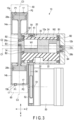
- FIG. 3 is a sectional view of the driving apparatus
- FIG. 4 is an exploded perspective view of a dual eccentric swinging linear motion mechanism of the driving apparatus.
- a driving apparatus 10 is configured as, for example, a compressor or a generator. As shown in FIGS. 1 , 2 and 3 , the driving apparatus 10 includes a housing (crank case) 12 shaped like an almost square tube, first and second cylinders 14a and 14b attached to the housing 12, a dual eccentric swinging linear motion mechanism (referred to as a swinging linear motion mechanism hereinafter) 20 provided in the housing 12 and the first and second cylinders 14a and 14b, and a motor 50 for rotating an outer shaft (first driving body) 22 of the swinging linear motion mechanism 20.
- a housing crank case
- first and second cylinders 14a and 14b attached to the housing 12
- a dual eccentric swinging linear motion mechanism referred to as a swinging linear motion mechanism hereinafter
- a motor 50 for rotating an outer shaft (first driving body) 22 of the swinging linear motion mechanism 20.
- the housing 12 includes a square-tube-like main body 12a and a plate-like end plate 12b that closes the opening of one end of the main body 12a.
- the inner surface of the body 12a is formed like a cylinder.
- a linear guide groove 12c is formed in the end plate 12b, to guide the linear motion of a swinging fulcrum to be described later.
- the first and second cylinders 14a and 14b are provided at the other end of the housing 12 and on both sides of a central axis C1 of the housing 12.
- the first and second cylinders 14a and 14b are arranged coaxially with each other, and the central axis C3 of the cylinders 14a and 14b is disposed so as to be orthogonal to the central axis C1 of the housing 12.
- Cylinder heads 15a and 15b which close the openings of the upper ends of the first and second cylinders 14a and 14b, are each provided with an outlet port P1, an inlet port P2 and a lead valve 17 for opening and closing these ports.
- first and second pistons 28a and 28b can be provided with an inlet port or the like.
- FIG. 4 is an exploded perspective view of the swinging linear motion mechanism 20.
- the swinging linear motion mechanism 20 includes an almost columnar-shaped outer shaft (first driving body) 22, an inner shaft (eccentric driving body) 24 provided eccentrically in the outer shaft 22, a first support pin (first pivot) 26a and a second support pin (second pivot) 26b which are provided at both ends of the inner shaft 24 in its axial direction, and first and second pistons 28a and 28b coupled to the first support pin 26a as moving bodies.
- the outer shaft 22 is disposed in the main body 12a of the housing 12 coaxially with the main body 12a. Both end portions of the outer shaft 22 in its axial direction are supported rotatably with respect to the housing 12 by a first bearing (e.g., a ball bearing) B1. That is, the inner ring of the first bearing B1 is fitted to the outer periphery of the outer shaft 22 and the outer ring thereof is fitted to the inner surface of the housing 12.
- a first bearing e.g., a ball bearing
- an annular driven pulley 41 is fixed on the outer surface of the outer shaft 22 and provided coaxially with the outer shaft 22.
- the driven pulley 41 may be formed integrally with the outer shaft 22 or another pulley may be fixed to the outer shaft 22.
- a circular through hole 30 is formed in the outer shaft 22.
- the through hole 30 has a central axis that is parallel to the central axis C1 of the outer shaft 22 and extends from one end of the outer shaft 22 to the other end thereof in its axial direction.
- the through hole 30 is also formed in a position eccentric to the central axis C1 of the outer shaft 22.
- a notch 32 may be provided in part of the outer surface of the outer shaft 22.
- the notch 32 is provided on the opposite side of the through hole 30 with respect to the central axis C1 of the outer shaft 22.
- the inner shaft 24 is almost shaped like a column and its outer diameter is slightly smaller than the inner diameter of the through hole 30.
- the inner shaft 24 is formed to substantially equal to the outer shaft 22 in its axial direction.
- the inner shaft 24 is inserted into the through hole 30.
- Both end portions of the inner shaft 24 in its axial direction are each rotatably supported with respect to the inner surface of the through hole 30, i.e., with respect to the outer shaft 22 by a second bearing (e.g., a ball bearing) B2.
- the inner ring of the second bearing B2 is fitted to the outer surface of the inner shaft 24 and the outer ring thereof is fitted to the inner surface of the through hole 30.
- the central axis C2 of the inner shaft 24 is located coaxially with the central axis of the through hole 30 and supported rotatably around the central axis C2.
- the central axis C2 of the inner shaft 24 is parallel to the central axis C1 of the outer shaft 22 and is eccentric to the central axis C1.
- the face of one end of the inner shaft 24 in its axial direction is substantially flush with that of one end of the outer shaft 22.
- the face of the other end of the inner shaft 24 is substantially flush with that of the other end of the outer shaft 22.
- a column-shaped first support pin 26a protrudes from the face of one end of the inner shaft 24 and a column-shaped second support pin 26b protrudes from the face of the other end of the outer shaft 22.
- the first and second support pins 26a and 26b extend parallel to the central axis of the inner shaft 24.
- the first and second support pins 26a and 26b are also provided at a position eccentric to the central axis of the inner shaft 24.
- first and second support pins 26a and 26b are provided 180 degrees away from each other around the central axis of the inner shaft 24.
- the first support pin 26a functions as a swinging load to be described later and the second support pin 26b functions as a swinging fulcrum to be described later.
- the first and second support pins 26a and 26b may be formed integrally with the inner shaft 24 or another support pint may rotatably be attached to the inner shaft 24.
- the inner shaft 24 has a counterweight that is formed by the inner shaft 24 itself. That is, part of one end of the inner shaft 24 is cut into an almost U-shaped portion and the other part thereof constitutes a first counterweight portion W1.
- the first counterweight portion W1 is provided across the central axis C2 of the inner shaft 24 from the first support pin 26a.
- Part of the other end of the inner shaft 24 is also cut into an almost U-shaped portion and the other part thereof constitutes a second counterweight portion W2.
- the second counterweight portion W2 is provided across the central axis C2 of the inner shaft 24 from the second support pin 26b.
- the swinging linear motion mechanism 20 includes first and second pistons 28a and 28b as moving bodies that move linearly.
- the first piston 28a is disposed in the first cylinder 14a.
- the first piston 28a is freely guide by the first cylinder 14a as a guide body to move up and down along the central axis C3 of the first cylinder 14a.
- the second piston 28b is disposed in the second cylinder 14b.
- the second piston 28b is freely guided by the second cylinder 14b as a guide body to move up and down along the central axis C3 of the second cylinder 14b.
- the first and second piston 28a and 28b are coupled to each other via a piston rod 34.
- the piston rod 34 extends coaxially with the central axis C3 of the first and second cylinders 14a and 14b.
- the central portion of the piston rod 34 in its axial direction is rotatably coupled to the first support pin 16a via a third bearing (e.g., a ball bearing, a cam follower and a slider) B3.
- a fourth bearing (e.g., a ball bearing and a slider) B4 is fitted to the second support pin 26b of the inner shaft 24.
- the fourth bearing B4 is engaged in the guide groove 12c formed on the end plate 12b.
- the second support pin 26b and the fourth bearing B4 are guided by the guide groove 12c of the end plate 12b as a guide body such that it can freely move linearly along the axial direction (X-axis direction) of the guide groove 12c.
- the extending direction of the central axis C1 of the outer shaft 22 is a Z-axis direction
- a direction orthogonal to the Z-axis direction is a Y-axis direction
- a direction orthogonal to the Z-axis and Y-axis directions is an X-axis direction.
- the central axis C2 of the first and second cylinders 14a and 14b extends in the Y-axis direction and the central axis of the guide groove 12c extends in the X-axis direction.
- the motor 50 is provided adjacent to the housing 12.
- the rotating shaft 51 of the motor 50 extends parallel to the central axis C1 of the outer shaft 22.
- a driving pulley 52 is attached to the rotating shaft 51.
- a driving belt 54 is put on the driving pulley 52 and the driven pulley 41 of the outer shaft 22.
- the motor 50 can rotate the outer shaft 22 around the central axis C1 via the driving pulley 52, driving belt 54 and driven pulley 41.
- the transmission of driving force is not limited to a combination of the pulleys and the driving belt, but the driving force can be transmitted using a plurality of gears.
- the motor 50 is driven to rotate the outer shaft 22 around the central axis C1.
- the inner shaft 24 rotates around the central axis C1 together with the outer shaft 22 and rotates on its central axis C2 with respect to the outer shaft 22.
- the rotation directions of the outer shaft 22 and the inner shaft 24 are opposite to each other.
- the first support pin 26a of the inner shaft 24 moves linearly along the Y-axis direction.
- the piston rod 34 coupled to the first support pin 26a via the third bearing B3 and the first and second pistons 28a and 28b reciprocate in the Y-axis direction in conjunction with the linear motion of the first support pin 26a.
- the first and second pistons 28a and 28b move up and down in the first and second cylinders 14a and 14b, respectively to compress and pressurize gas in the cylinders.
- the driving apparatus 10 with the forgoing configuration can function as a compressor by discharging gas compressed in the first and second cylinders 14a and 14b from the outlet port P1.
- FIG. 5 is a schematic diagram showing a plane and a configuration point by which the dual eccentric swinging linear motion mechanism 20 is configured.
- FIG. 6 is a schematic diagram showing a relationship in position among the central axis C1 of the outer shaft (first driving body), a rotating central axis thereof, and the inner shaft (eccentric driving body).
- FIG. 7 is a diagram showing trajectories of a swinging load, a swinging fulcrum and a virtual swinging effort.
- a first plane (Y-axis constraining plane) S1 and a second plane (X-axis constraining plane) S2 are parallel to each other and a virtual third plane S3 is located between the first and second planes and parallel to these planes.
- the central axis C1 of the outer shaft (first driving body) 22 and the central axis C2 of the inner shaft 24 are orthogonal to the first to third planes S1, S2 and S3.
- a new mechanism is configured by providing a new reference plane in the parallel planes and virtually defining an extending axis.
- the inner shaft 24 that is rotatably supported by the outer shaft 22 has the central axis C2 eccentric to the central axis C1 of the outer shaft 22.
- the inner shaft 24 is a rotating body including the first support pin 26a as a swinging load and a second support pin 26b as a swinging fulcrum on the outer surface side.
- the swinging load 26a and swinging fulcrum 26b are constrained in their respective Y-axis and X-axis directions and move linearly.
- the first support pin (swinging load) 26a which moves linearly in the Y-axis direction is present on the first plane (Y-axis constraining plane) S1.
- the second support pin (swinging fulcrum) 26b which moves linearly in the X-axis direction is present on the second plane (X-axis constraining plane) S2.
- the third plane S3 is a virtual projection plane including a virtual swinging load M1 and a virtual swinging fulcrum M2 on which the swinging load 26a and the swinging fulcrum 26b are respectively projected and a virtual swinging effort M3 at which a straight line connecting the virtual swinging load M1 and virtual swinging fulcrum M2 intersects the central axis C2 of the inner shaft (eccentric driving body) 24.
- the virtual swinging effort M3 is regarded as being connected to the rotation axis C1 of the outer shaft 22 by the straight line.
- the Y-axis direction is a trajectory of linear motion of the swinging load 26a and the first and second pistons 28a and 28b
- the X-axis direction is a trajectory of linear motion of the swinging fulcrum 26b.
- the trajectory of a small circle with the central axis C1 corresponds to that of the virtual swinging effort M3 of the inner shaft 24. It is a virtual lever that connects the swinging load 26a, swinging fulcrum 26b and the virtual swinging effort M3 and, in fact, it is included in the inner shaft 24 rotatably inserted into the outer shaft 22.
- Each of the swinging points is separated in the Y-axis and X-axis directions and makes a swinging motion.
- the swinging fulcrum 26b and the virtual swinging fulcrum axis Z1 are removed, they appear to rotate and reciprocate; however, a problem of dead points will occur to bring them into an unstable state in which they move or do not move and they do not rotate in a fixed direction.
- the swinging fulcrum 26b overcomes a dead point and swings in the X-axis direction because its motion is constrained in the x-axis direction. It is therefore possible to allow the outer shaft 22 and the inner shaft 24 to rotate in a fixed direction.
- FIG. 8A is a schematic diagram showing a relationship in position between the outer and inner shafts on the projection plane S3.
- FIG. 8B is a diagram showing a relationship between points and segments on the projection plane S3.
- the displacement YM of the virtual swinging load M1 is represented by the following equation using Y1 and Y2 in relation to the virtual swinging effort M3.
- the displacement XM of the virtual swinging fulcrum M2 is represented by the following equation using X1 and X2 in relation to the virtual swinging effort M3.
- XM X1 + X2
- the virtual points M1 and M2 are present on their respective virtual axes Z2 and Z1.
- the virtual axes Z2 and Z1 are present on a normal in the Z-axis direction of the swinging load 26a and swinging fulcrum 26b. Therefore, the actual displacements of the swinging load 26a and the swinging fulcrum 26b are equal to the displacement YM of the virtual swinging load M1 and the displacement XM of the virtual swinging fulcrum M2.
- the dual eccentric swinging linear motion mechanism 20 is provided with the swinging fulcrum 26b and the guide body which guides the swinging fulcrum 26b to be linearly movable.
- the driving body can overcome a dead point and rotate in one direction with reliability, and the swinging load 26a can move linearly with reliability. That is, the outer shaft 22 and the inner shaft 24 can rotate in one direction with reliability, and the first and second support pins 26a and 26b can move linearly in their respective Y-axis and X-axis directions.
- the outer shaft 22 is rotated by the motor 50 and thus gas in the first and second cylinders 14a and 14b is compressed by the first and second pistons 28a and 28b, with the result that the driving apparatus can serve as a compressor.
- the upper and lower first and second pistons 28a and 28b having different diameters are configured as a two-stage compression mechanism, a CO2 refrigerant refrigerating machine using, e.g., a motor capable of compressing a refrigerant at high pressure (e.g., close to 12 MPa) as the motor 50.
- each of the cylinder heads is provided with a combustion mechanism 60 including a valve mechanism, a fuel supply means and an ignition means, as shown in FIG. 3 . It is thus possible to supply fuel into the first and second cylinders 14a and 14b and ignite the fuel, and also drive the first and second pistons 28a and 28b in the Y-axis direction.
- the driving apparatus 10 can thus function as an engine.
- the motor 50 can be used as a starter.
- the inner and outer shafts 24 and 22 are rotated by the first and second pistons 28a and 28b and further, the motor 50 is driven by the outer shaft 22, with the result that the motor 50 can function as a generator.
- the vibration of the swinging linear motion mechanism 20 can be canceled by providing the inner shaft 24 with the counterweight portions W1 and W2. Furthermore, the overall apparatus can be compacted by configuring the counterweights by the inner shaft 24 itself.
- the position to keep a balance is not limited to the embodiment but can be set optionally in accordance with the capacity of the motor 50, the diameter of the pistons, a method of attaching the counterweights, and the like.
- the driving apparatus is thus excellent in convenience.
- the outer shaft 22, inner shaft 24 and first and second support pins 26a and 26b of the swinging linear motion mechanism 20 can axially be supported by bearings or the like, which makes it possible to operate the driving apparatus for a long time.
- the driving apparatus 10 includes two cylinders; however, it may include a single cylinder.
- the single cylinder can keep a balance and easily decrease the size of the driving apparatus.
- the second support pin (swinging fulcrum) 26b can be supported by a cam follower or a slider shaped like a rectangular block as well as the ball bearing and optionally take the shape capable of overcoming a dead point by the swinging fulcrum.
- the rectangular block-shaped slider it may have a through hole into which the second support pin is rotatably inserted and may also be divided into two by a dividing surface crossing the through hole, on which concave and convex surfaces can be formed side by side in the axial direction of the second support pin.
- FIG. 9 is a perspective view showing a driving apparatus according to a second embodiment.
- FIG. 10 is a perspective view schematically showing structural elements of the driving apparatus according to the second embodiment.
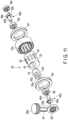
- FIG. 11 is an exploded perspective view of a swinging linear motion mechanism of the driving apparatus according to the second embodiment.
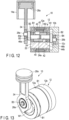
- FIG. 12 is a sectional view of the driving apparatus according to the second embodiment.
- a driving apparatus 10 is configured as a one-cylinder compressor with a built-in motor or a generator with an engine.
- a plurality of magnets 40 are fixed on the outer surface of an outer shaft 22.
- the magnets 40 extend parallel to the central axis C1 of the outer shaft 22 and are arranged at predetermined intervals in the circumferential direction of the outer shaft 22.
- a cylindrical magnet having a plurality of poles can be used.
- the main body 12a of a housing 12, which is a stator, is formed like a cylinder and disposed coaxially with the outer shaft 22 on the outside of the outer shaft 22.
- Either end portion of the outer shaft 22 in its axial direction is supported by a bearing B1 such that it can rotate relative to the housing 12.
- the outer shaft 22 and the magnets 40 constitute a rotor of the motor.
- An excitation coil 42 is provided on the inner surface side of the main body 12a and opposed to the magnets 40.
- the main body 12a and excitation coil 42 constitute a stator for applying a magnetic field to the magnets 40.
- the outer shaft 22, magnets 40, main body 12a and excitation coil 42 constitute a motor.
- the excitation coil 42 is energized to generate a driving magnetic field, the outer shaft 22 can be rotated.
- a crankshaft will be described by dividing it into elements 26a, 44a, 45a and 46a.
- the inner shaft 24 is disposed in a through hole 30 of the outer shaft 22 and its axial-direction end portions are supported by a pair of bearings B2 such that they can rotate relative to the outer shaft 22.
- a circular through hole 24a is formed in the inner shaft 24.
- the through hole 24a is provided coaxially with the central axis C2 of the inner shaft 24.
- a first crank pin 45a including the first support pin 26a is provided at one end of the inner shaft 24 in its axial direction.
- the first crank pin 45a includes a fitting pin 44a, a crank plate 46a orthogonal to the fitting pin 44a and a first support pin 26a protruding from the crank plate 46a, which are formed integrally as one unit.
- the first support pin 26a is provided parallel and eccentrically to the fitting pin 44a.
- the first crank pin 45a is fixed to the inner shaft 24 with the fitting pin 44a into the through hole 24a.
- the first support pin 26a extends in the Z-axis direction eccentrically to the inner shaft 24.
- a second crank pin 45b including a second support pin 26b is provided at the other end of the inner shaft 24 in its axial direction.
- the second crank pin 45b includes a fitting pin 44b, a crank plate 46b orthogonal to the fitting pin 44b and a second support pin 26b protruding from the crank plate 46a, which are formed integrally as one unit.
- the second support pin 26b is provided parallel and eccentrically to the fitting pin 44b.
- the second crank pin 45b is fixed to the inner shaft 24 with the fitting pin 44b into the through hole 24a.
- the second support pin 26b extends in the Z-axis direction eccentrically to the inner shaft 24.
- a piston rod 34 is coupled to the first support pin 26a through a bearing B3.
- the piston rod 34 is coupled to a first piston 28a, and the first piston 28a is guided by the first cylinder 14a such that it can reciprocate in the Y-axis direction.
- a bearing B4 is fitted to the second support pin 26b, and the bearing B4 is guided by a guide groove 12c such that it can move linearly along the X-axis direction.
- the inner shaft 24 includes counterweight portions W1 and W2.
- the second support pin 26b can be supported by a cam follower or a slider shaped like a rectangular block as well as the ball bearing. The descriptions of the other configurations will be omitted because they are similar to those of the first embodiment.
- the outer shaft 22 is rotated by the built-in motor to move the first piston 28a up and down in the Y-axis direction and compress and pressurize gas in the first cylinder 14a. It is thus possible to configure an integrated compressor by the driving apparatus 10. Furthermore, a cylinder head is provided with a combustion mechanism including a valve mechanism, a fuel supply means and an ignition means to make it possible to supply fuel into the first cylinder 14a and ignite the fuel and drive the first piston 28a in the Y-axis direction.
- the driving apparatus 10 can thus function as an engine.
- the inner and outer shafts 24 and 22 are rotated by the first piston 28a, with the result that the driving apparatus 10 can function as a generator that generates power from a motor.
- the built-in motor can decrease the size of the entire apparatus and also reduce power consumption. Furthermore, the crank plates 46a and 46b of the first and second crank pins 45a and 45b can function as a flywheel, with the result that both stable rotation and linear motion can be performed.
- FIG. 13 is a perspective view showing a driving apparatus according to a third embodiment.
- FIG. 14 is an exploded perspective view of a swinging linear motion mechanism of the driving apparatus according to the third embodiment.
- FIG. 15 is a sectional view of the driving apparatus according to the second embodiment.
- the counterweights are not formed on the inner shaft 24 but provided independently on both ends of the inner shaft 24 in its axial direction. That is, the inner shaft 24 is formed like a cylinder having a coaxial through hole.
- the crank plate of the first crank pin 45a composes a counterweight W1.
- the crank plate of the second crank pin 45b composes a counterweight W2.
- the fitting pin 44a of the first crank pin 45a is fitted into the through hole 24a of the inner shaft 24 and thus the counterweight W1 is provided between the bearings B2 and B3 at one end of the inner shaft 24.
- the fitting pin 44b of the second crank pin 45b is fitted into the through hole 24a of the inner shaft 24 and thus the counterweight W2 is provided between the bearings B2 and B4 at the other end of the inner shaft 24.
- the other configurations of the driving apparatus 10 are the same as those of the driving apparatus according to the second embodiment described above.
- FIG. 16 is a sectional view of a driving apparatus according to a third embodiment.
- the driving apparatus 10 includes a single independent counterweight W1.
- the counterweight W1 is attached to the first support pin 26a and located outside a bearing B3. That is, the bearing b3 and piston rod 34 are placed between the crank plate 46a of the first crank pin 45a and the counterweight W1.
- the single counterweight W1 has only to be placed on the piston side, which is effective, e.g., when a balance needs to be kept after the assembly.
- the other configuration of the driving apparatus 10 is the same as those of the driving apparatus according to the second embodiment described above.
- FIG. 17 is a perspective view showing a driving apparatus according to a fifth embodiment.
- FIG. 18 is a partially cutaway perspective view of the driving apparatus according to the fifth embodiment.
- the driving apparatus 10 is configured as a cross four-cylinder driving apparatus. As shown in FIGS. 17 and 18 , the driving apparatus 10 includes a third cylinder 14c and a fourth cylinder 14d which are attached to a one end portion of the housing 12 in addition to the first cylinder 14a and second cylinder 14b which are attached to the housing 12.
- the first and second cylinders 14a and 14b are provided at the one end portion of the housing 12 and also provided on both sides of the central axis C1 of the housing 12.
- the first and second cylinders 14a and 14b are arranged coaxially with each other and their central axis C3 extends along the Y-axis direction orthogonal to the central axis C1 of the housing 12.
- the cylinder heads 15a and 15b which close the upper openings of the first and second cylinders 14a and 14b, are provided with an intake/exhaust mechanism, a fuel supply mechanism, an ignition means and the like, neither of which is shown.
- the third and fourth cylinders 14c and 14d are provided at the other end portion of the housing 12 and also provided on both sides of the central axis C1 of the housing 12.
- the third and fourth cylinders 14c and 14d are arranged coaxially with each other and their central axis C4 extends along the X-axis direction orthogonal to the central axis C1 of the housing 12. That is, the central axis C4 of the cylinders 14c and 14d extends in a direction that is 90 degrees inverted from the central axis C3 of the first and second cylinders 14a and 14b.
- the cylinder heads 15c and 15d which close the upper openings of the third and fourth cylinders 14c and 14d, are provided with an intake/exhaust mechanism, a fuel supply mechanism, an ignition means and the like, neither of which is shown.
- the swinging linear motion mechanism 20 includes a first piston 28a provided in the first cylinder 14a and a second piston 28b provided in the second cylinder 14b.
- the first and second pistons 28a and 28b are coupled to each other by a piston rod 34 extending in the Y-axis direction.
- the central portion of the piston rod 34 is rotatably coupled to the first support pin 26a of the inner shaft 24 through the bearing B3.
- the first and second pistons 28a and 28b are guided by the first and second cylinders 14a and 14b and move linearly in the Y-axis direction.
- the swinging linear motion mechanism 20 includes a third piston 28c provided in the third cylinder 14c and a fourth piston 28d provided in the fourth cylinder 14d.
- the third and fourth pistons 28c and 28d are coupled to each other by a piston rod 34 extending in the X-axis direction.
- the central portion of the piston rod 34 is rotatably coupled to the second support pin 26b of the inner shaft 24 through the bearing B4. As the outer and inner shafts 22 and 24 rotate, the third and fourth pistons 28c and 28d are guided by the third and fourth cylinders 14c and 14d and move linearly in the X-axis direction.
- the other configurations of the swinging linear motion mechanism 20 are the same as those of the swinging linear motion mechanism 20 in the first embodiment described above.
- the driving apparatus 10 configured as described above can bring about the same advantages as those of the driving apparatus according to the first embodiment described above. Since the third and fourth pistons 28c and 28d that move linearly in the X-axis direction are provided, the inner and outer shafts 24 and 22 can be rotated through the second support pin 26b. Since, furthermore, the third and fourth pistons are provided to move linearly in the X-axis direction that is 90 degrees shifted from the Y-axis direction that is a motion direction of the first and second pistons 28a and 28b, a Stirling engine can be configured.
- FIG. 19 is a perspective view showing a driving apparatus according to a sixth embodiment.
- FIG. 20 is a partially cutaway perspective view of the driving apparatus according to the sixth embodiment.
- the driving apparatus 10 is configured as a parallel four-cylinder driving apparatus including mirrors. As shown in FIGS. 19 and 20 , the driving apparatus 10 includes a first driving device 10a and a second driving device 10b which have the same configuration as that of the driving apparatus according to the first embodiment described above. The first and second driving devices 10a and 10b are arranged symmetrically with regard to a central plane SC.
- the housing 12 includes a rectangular main body 12a common to the first and second driving devices 10a and 10b and a common end plate 12b that closes the opening of the main body 12a at one end.
- the first driving device 10a includes a first cylinder 14a and a second cylinder 14b which are provided in the housing 12.
- the first and second cylinders 14a and 14b are provided coaxially with each other and along the Y-axis direction.
- the second driving device 10b includes a third cylinder 14c and a fourth cylinder 14b which are provided in the housing 12.
- the third and fourth cylinders 14c and 14d are provided coaxially with each other and along the Y-axis direction. That is, the third and fourth cylinders 14c and 14d are provided parallel to the first and second cylinders 14a and 14b.
- the configuration of the swinging linear motion mechanism 20 in the housing 12 and the first and second cylinders 14a and 14b and that of the swinging linear motion mechanism 20 in the housing 12 and the third and fourth cylinders 14c and 14d are common to each other, and the common configuration is the same as that of the swinging linear motion mechanism 20 of the driving apparatus according to the first embodiment described above.
- a ring gear 70 is fixed on the outer surface of the outer shaft 22 of the first driving device 10a coaxially with the outer shaft 22.
- a ring gear 70 is fixed on the outer surface of the outer shaft 22 of the second driving device 10b coaxially with the outer shaft 22.
- These ring gears 70 are formed to have the same diameter and the same number of teeth and engaged with each other. Accordingly, the outer shaft 22 of the first driving device 10a and the outer shaft 22 of the second driving device 10b are coupled to each other via the ring gears 70. When one of the outer shafts 22 rotates, the other outer shaft 22 rotates in the opposite direction in synchronization with the former rotation.
- the outer shaft 22 of the first driving device 10a and the outer shaft 22 of the second driving device 10b rotate in opposite directions in synchronization with each other.
- the two ring gears 70 thus constitutes a coupling synchronization mechanism that rotates the two outer shafts 22 in opposite directions in synchronization with each other.
- the swinging linear motion mechanism 20 including the first and second pistons 28a and 28b and the swinging linear motion mechanism 20 including the third and fourth pistons 28c and 28d can rotate and move linearly while maintaining conditions symmetrical with each other.
- the driving apparatus 10 with the foregoing configuration can bring about the same advantage as that of the first embodiment described above.
- the two outer shafts 22 can rotate in opposite directions in synchronization with each other by driving the first to fourth pistons 28a to 28b.
- the first to fourth cylinders 24a to 28d can output the synchronized output by rotating at least one of the outer shafts 22 by the motor or the like.
- a basic vibration and an operation loss can be removed to achieve a quieter rotating body by mirror-arranging the first and second driving devices 10a and 10b. If the cylinders are shaped in the form of letter "U" in particular, high-pressure and low-pressure pistons are arranged side by side, which allows gas to move easily.
- the driving apparatus can thus be decreased in size.
- FIG. 21 is a partially cutaway perspective view showing a driving apparatus according to a seventh embodiment.
- the driving apparatus 10 is configured as a parallel two-cylinder driving apparatus including mirrors.
- the driving apparatus 10 is not limited to the foregoing four-cylinder driving apparatus but may be a two-cylinder driving apparatus.
- the driving apparatus 10 includes a first driving device 10a having a first piston 28a disposed in the first cylinder 14a and the first cylinder 14a and a second driving device 10b having a second piston 28b disposed in the second cylinder 14b and the second cylinder 14b.
- the first and second driving devices 10a and 10b are arranged and configured symmetrically with each other with regard to the central plane SC.
- the housing 12 includes a rectangular main body 12a common to the first and second driving devices 10a and 10b and a common end plate 12b that closes the opening of the main body 12a at one end.
- a ring gear 70 is fixed on the outer surface of the outer shaft 22 of the first driving device 10a coaxially with the outer shaft 22.
- a ring gear 70 is fixed on the outer surface of the outer shaft 22 of the second driving device 10b coaxially with the outer shaft 22.
- These ring gears 70 are formed to have the same diameter and the same number of teeth and engaged with each other. Accordingly, the outer shaft 22 of the first driving device 10a and the outer shaft 22 of the second driving device 10b are coupled to each other via the ring gears 70. When one of the outer shafts 22 rotates, the other outer shaft 22 rotates in the opposite direction in synchronization with the former rotation.
- the outer shaft 22 of the first driving device 10a and the outer shaft 22 of the second driving device 10b rotate in opposite directions in synchronization with each other. Since, furthermore, the first and second driving devices 10a and 10b are arranged and configured symmetrically with regard to the central plane SC, the swinging linear motion mechanisms 20 including the first and second pistons 28a and 28b can rotate and move linearly while maintaining conditions symmetrical with each other.
- the other configurations of the driving apparatus are the same as those of the sixth embodiment described above.
- the foregoing two-cylinder driving apparatus 10 can also bring about the same advantages as those of the first and sixth embodiments described above.
- the two outer shafts 22 can rotate in opposite directions in synchronization with each other by driving the first and second pistons 28a to 28b.
- the first and second cylinders 24a and 28b can output the synchronized output by rotating at least one of the outer shafts 22 by the motor or the like.
Landscapes
- Engineering & Computer Science (AREA)
- General Engineering & Computer Science (AREA)
- Mechanical Engineering (AREA)
- Chemical & Material Sciences (AREA)
- Combustion & Propulsion (AREA)
- Ocean & Marine Engineering (AREA)
- Physics & Mathematics (AREA)
- Acoustics & Sound (AREA)
- Aviation & Aerospace Engineering (AREA)
- Transmission Devices (AREA)
Claims (14)
- Antriebsvorrichtung, umfassend:ein Gehäuse (12);einen ersten Antriebskörper (22), der in dem Gehäuse so vorgesehen ist, dass er um eine erste Mittelachse drehbar ist;dadurch gekennzeichnet, dass die Antriebsvorrichtung weiter einen exzentrischen Antriebskörper (24) umfasst, der in dem ersten Antriebskörper vorgesehen ist, sodass er eine zweite Mittelachse parallel zur ersten Mittelachse drehbar ist und um die erste Mittelachse drehbar ist;einen ersten Drehpunkt (26a), der an einem Ende des exzentrischen Antriebskörpers in einer Achsenrichtung und exzentrisch zur zweiten Mittelachse vorgesehen ist und sich parallel zur zweiten Mittelachse erstreckt;einen zweiten Drehpunkt (26b), der an einem anderen Ende des exzentrischen Antriebskörpers in der Achsenrichtung und exzentrisch zur zweiten Mittelachse vorgesehen ist und sich parallel zur zweiten Mittelachse erstreckt;einen ersten Bewegungskörper, der drehbar mit dem ersten Drehpunkt (26a) verbunden ist und sich linear entlang einer dritten Mittelachse orthogonal zur ersten Mittelachse bewegt;einen ersten Führungskörper, der die Bewegung des ersten Bewegungskörpers entlang der dritten Mittelachse führt; undeinen zweiten Führungskörper, der den zweiten Drehpunkt (26b) so führt, dass er in einer ersten Richtung orthogonal zu der ersten Mittelachse linear bewegbar ist.
- Vorrichtung nach Anspruch 1, wobei:der erste Führungskörper einen ersten Zylinder (14a) aufweist, der koaxial zur dritten Mittelachse vorgesehen ist; undder erste Bewegungskörper einen ersten Kolben (28a), der in dem ersten Zylinder (14a) vorgesehen ist, und eine mit dem ersten Kolben verbundene Kolbenstange (34) aufweist, die sich entlang der dritten Mittelachse erstreckt und über ein Lager drehbar mit dem ersten Drehpunkt (26a) verbunden ist.
- Vorrichtung nach Anspruch 1, wobei:der erste Führungskörper einen ersten Zylinder (14a) und einen zweiten Zylinder (14b) umfasst, die auf beiden Seiten der ersten Mittelachse koaxial mit der dritten Mittelachse vorgesehen sind; undder erste Bewegungskörper einen ersten Kolben (28a), der in dem ersten Zylinder vorgesehen ist, einen zweiten Kolben (28b), der in dem zweiten Zylinder vorgesehen ist, und eine Kolbenstange (34) umfasst, die mit dem ersten Kolben (28a) und dem zweiten Kolben (28b) verbunden ist und sich entlang der dritten Mittelachse erstreckt, wobei die Kolbenstange über ein Lager drehbar mit dem ersten Drehpunkt (26a) verbunden ist.
- Vorrichtung nach einem der Ansprüche 1 bis 3, wobei der erste Antriebskörper durch eine säulenförmige Außenwelle (22) ausgebildet ist, axiale Endabschnitte der Außenwelle durch Lager drehbar am Gehäuse (12) gelagert sind, die Außenwelle eine koaxial zur zweiten Mittelachse ausgebildete Durchgangsbohrung (30) aufweist, der exzentrische Antriebskörper durch eine säulenförmige Innenwelle (24) ausgebildet ist, und die Innenwelle in der Durchgangsbohrung der Außenwelle angeordnet und durch ein Lager drehbar an der Außenwelle gelagert ist.
- Vorrichtung nach Anspruch 4, bei der der erste Drehpunkt (26a) und der zweite Drehpunkt (26b) in der Innenwelle (24) in einer Position vorgesehen sind, die exzentrisch zur Mittelachse der Innenwelle ist.
- Vorrichtung nach einem der Ansprüche 1 bis 5, weiter umfassend ein Lager, ein Eingriffsglied oder einen Schieber, der drehbar an dem zweiten Drehpunkt (26b) angebracht ist,
wobei der zweite Führungskörper eine Führungsnut (12c) aufweist, die sich in der ersten Richtung erstreckt, und das Lager, das Eingriffsglied oder der Schieber in die Führungsnut eingepasst ist, um in der ersten Richtung bewegbar zu sein. - Vorrichtung nach einem der Ansprüche 1 bis 5, weiter umfassend einen zweiten Bewegungskörper, der drehbar mit dem zweiten Drehpunkt (26b) verbunden und linear in der ersten Richtung bewegbar ist, wenn sich der zweite Drehpunkt bewegt.
- Vorrichtung nach Anspruch 7, wobei:der zweite Führungskörper einen dritten Zylinder (14c) und einen vierten Zylinder (14d) aufweist, die auf beiden Seiten der ersten Mittelachse koaxial zur ersten Richtung angeordnet sind; undder zweite Bewegungskörper einen dritten Kolben (28c), der in dem dritten Zylinder vorgesehen ist, einen vierten Kolben (28d), der in dem vierten Zylinder vorgesehen ist, und eine Kolbenstange (34) umfasst, die mit dem dritten Kolben und dem vierten Kolben verbunden ist und sich entlang der ersten Richtung erstreckt, wobei die Kolbenstange über ein Lager drehbar mit dem zweiten Drehpunkt verbunden ist.
- Vorrichtung nach Anspruch 4 oder 5, wobei die Innenwelle (24) einen Gegengewichtsabschnitt (W1, W2) aufweist, der mit dieser einstückig als eine Einheit ausgebildet ist.
- Vorrichtung nach einem der Ansprüche 1 bis 9, weiter umfassend einen Motor, der den ersten Antriebskörper dreht.
- Vorrichtung nach einem der Ansprüche 1 bis 9, weiter umfassend Magneten (40), die an dem ersten Antriebskörper vorgesehen sind, und Statoren, die um den ersten Antriebskörper herum und den Magneten gegenüberliegend vorgesehen sind.
- Vorrichtung nach einem der Ansprüche 1 bis 8, weiter umfassend ein erstes Gegengewicht (W1), das am ersten Drehpunkt (26a) vorgesehen ist, und ein zweites Gegengewicht (W2), das am zweiten Drehpunkt (26b) vorgesehen ist.
- Vorrichtung nach Anspruch 2, weiter umfassend einen Verbrennungsmechanismus (60), der dem ersten Zylinder (14a) einen Brennstoff zuführt und den Brennstoff zündet.
- Antriebsvorrichtung, umfassend:eine erste Antriebsvorrichtung (10a), wobei die erste Antriebsvorrichtung eine Vorrichtung nach einem der Ansprüche 1 bis 10 ist; undeine zweite Antriebsvorrichtung (10b), die auf die gleiche Weise wie die erste Antriebsvorrichtung ausgebildet und symmetrisch zur ersten Antriebsvorrichtung in Bezug auf eine zentrale Ebene angeordnet ist,wobei die erste Antriebsvorrichtung und die zweite Antriebsvorrichtung einen Kupplungssynchronisationsmechanismus umfassen, der den ersten Antriebskörper der ersten Antriebsvorrichtung und den ersten Antriebskörper der zweiten Antriebsvorrichtung in entgegengesetzten Richtungen synchron zueinander dreht.
Applications Claiming Priority (1)
| Application Number | Priority Date | Filing Date | Title |
|---|---|---|---|
| PCT/JP2016/089127 WO2018123029A1 (ja) | 2016-12-28 | 2016-12-28 | 揺動直線運動機構を備えた駆動装置 |
Publications (3)
| Publication Number | Publication Date |
|---|---|
| EP3495609A1 EP3495609A1 (de) | 2019-06-12 |
| EP3495609A4 EP3495609A4 (de) | 2020-01-08 |
| EP3495609B1 true EP3495609B1 (de) | 2023-12-27 |
Family
ID=62707108
Family Applications (1)
| Application Number | Title | Priority Date | Filing Date |
|---|---|---|---|
| EP16925480.2A Active EP3495609B1 (de) | 2016-12-28 | 2016-12-28 | Antriebsvorrichtung mit schwingendem linearbewegungsmechanismus |
Country Status (4)
| Country | Link |
|---|---|
| US (1) | US10519853B2 (de) |
| EP (1) | EP3495609B1 (de) |
| JP (1) | JP6376634B1 (de) |
| WO (1) | WO2018123029A1 (de) |
Families Citing this family (4)
| Publication number | Priority date | Publication date | Assignee | Title |
|---|---|---|---|---|
| CN205586102U (zh) * | 2014-12-01 | 2016-09-21 | 洁碧有限公司 | 防水无线口腔冲洗器 |
| CN109373963B (zh) * | 2018-11-29 | 2025-02-11 | 南京伶机宜动驱动技术有限公司 | 摆转动直驱平台 |
| CN112932105B (zh) * | 2021-02-10 | 2022-09-16 | 贵州电网有限责任公司 | 一种蓄电池存放货架 |
| JP2025003172A (ja) * | 2023-06-23 | 2025-01-09 | ナブテスコ株式会社 | 揺動直線駆動機構を備えた駆動装置 |
Family Cites Families (24)
| Publication number | Priority date | Publication date | Assignee | Title |
|---|---|---|---|---|
| US1056746A (en) * | 1911-03-01 | 1913-03-18 | Pitts Royalty Company | Mechanical movement. |
| US2166975A (en) * | 1936-10-10 | 1939-07-25 | Sologaistoa Manuel Humbe Perez | Mechanical movement |
| US2223100A (en) * | 1938-04-01 | 1940-11-26 | Edwin E Foster | Internal combustion engine |
| US3258992A (en) * | 1963-02-15 | 1966-07-05 | John L Hittell | Reciprocating piston engines |
| JPS4829913A (de) * | 1971-08-24 | 1973-04-20 | ||
| US4270395A (en) * | 1977-06-30 | 1981-06-02 | Grundy Reed H | Motion translating mechanism |
| US4485768A (en) * | 1983-09-09 | 1984-12-04 | Heniges William B | Scotch yoke engine with variable stroke and compression ratio |
| JP2683218B2 (ja) * | 1994-05-10 | 1997-11-26 | ロングウェルジャパン株式会社 | クランク装置 |
| JP3425736B2 (ja) | 1996-10-28 | 2003-07-14 | Lwj株式会社 | クランク装置 |
| US5782213A (en) * | 1997-04-07 | 1998-07-21 | Pedersen; Laust | Internal combustion engine |
| DE69819730T2 (de) * | 1997-07-15 | 2004-09-30 | New Power Concepts Llc | Brennverfahren |
| JP4226160B2 (ja) | 1999-08-20 | 2009-02-18 | Lwj株式会社 | コンプレッサ |
| JP2002285972A (ja) | 2001-03-26 | 2002-10-03 | Okinawa Kaihatsuchiyou Okinawa Sogo Jimukiyokuchiyou | コンプレッサユニット |
| US6742482B2 (en) | 2001-08-22 | 2004-06-01 | Jorge Artola | Two-cycle internal combustion engine |
| EP1595063A1 (de) * | 2003-01-23 | 2005-11-16 | Jorge Artola | Zweitaktverbrennungsmotor |
| US7185557B2 (en) * | 2004-06-29 | 2007-03-06 | Thomas Mark Venettozzi | Epitrochoidal crankshaft mechanism and method |
| US7654802B2 (en) * | 2005-12-22 | 2010-02-02 | Newport Medical Instruments, Inc. | Reciprocating drive apparatus and method |
| WO2008010490A1 (en) * | 2006-07-18 | 2008-01-24 | Univ Shizuoka Nat Univ Corp | Cycloid reciprocating engine and pump employing this crank mechanism |
| WO2008085920A2 (en) * | 2007-01-05 | 2008-07-17 | Efficient-V, Inc. | Motion translation mechanism |
| JP5753343B2 (ja) * | 2009-07-07 | 2015-07-22 | 孝 松田 | 遊星歯車複偏心盤を用いた2気筒1クランクピン型多気筒サイクロイド往復動機関 |
| JP4553977B1 (ja) * | 2009-10-26 | 2010-09-29 | 有限会社ケイ・アールアンドデイ | ロータリ式シリンダ装置 |
| US20110146601A1 (en) * | 2009-12-22 | 2011-06-23 | Fisher Patrick T | Self-Aspirated Reciprocating Internal Combustion Engine |
| JP5393907B1 (ja) * | 2012-11-09 | 2014-01-22 | 有限会社タック リサーチ | Xy分離クランク機構およびこれを備えた駆動装置 |
| JP6052748B2 (ja) * | 2015-03-03 | 2016-12-27 | Zメカニズム技研株式会社 | Xy分離クランク機構を備えた駆動装置 |
-
2016
- 2016-12-28 WO PCT/JP2016/089127 patent/WO2018123029A1/ja not_active Ceased
- 2016-12-28 EP EP16925480.2A patent/EP3495609B1/de active Active
- 2016-12-28 JP JP2018508779A patent/JP6376634B1/ja active Active
-
2019
- 2019-03-08 US US16/297,407 patent/US10519853B2/en active Active
Also Published As
| Publication number | Publication date |
|---|---|
| EP3495609A4 (de) | 2020-01-08 |
| US10519853B2 (en) | 2019-12-31 |
| JP6376634B1 (ja) | 2018-08-22 |
| EP3495609A1 (de) | 2019-06-12 |
| WO2018123029A1 (ja) | 2018-07-05 |
| US20190203639A1 (en) | 2019-07-04 |
| JPWO2018123029A1 (ja) | 2018-12-27 |
Similar Documents
| Publication | Publication Date | Title |
|---|---|---|
| US10519853B2 (en) | Driving apparatus with swinging linear motion mechanism | |
| US6321693B1 (en) | Reciprocating rotary piston system and pressure pump and internal combustion engine using the same | |
| AU2008287615B2 (en) | An axial piston machine with rotation restraint mechanism | |
| EP3272998B1 (de) | Antriebsvorrichtung mit xy-trennendem kurbelmechanismus | |
| US8443713B2 (en) | Rotary cylinder device | |
| JP6573605B2 (ja) | 遊星回転機構を有するスピン・ポンプ | |
| CN101605991B (zh) | 往复式压缩机 | |
| JP6682616B2 (ja) | 流体機械、熱交換装置及び流体機械の運転方法 | |
| WO2009100759A1 (en) | A reciprocating piston mechanism and a method of increasing internal egr in an internal combustion engine | |
| US7140343B2 (en) | Overload protection mechanism | |
| EP2604889B1 (de) | Kreisförmiger gleitschuhmechanismus einer kurbel, teile davon und gerät daraus | |
| US20160025080A1 (en) | Apparatus including swashplates fixed on shaft assembly and piston assemblies | |
| EP2633207B1 (de) | Axialkolbenmaschinen | |
| KR20000029539A (ko) | 회전운동기구및엔진 | |
| JP6276753B2 (ja) | 多角形振動ピストンエンジン | |
| US7827901B2 (en) | Free swinging piston heat machine | |
| CN101865268B (zh) | 一种曲柄圆滑块机构及其曲轴、应用该机构的设备 | |
| JP4041173B2 (ja) | 低振動容積型機械 | |
| US20100031916A1 (en) | Hypocycloid Engine | |
| US20130220040A1 (en) | Vibration-free opposed piston engine | |
| JP5010742B2 (ja) | ピストン機械 | |
| JP5571358B2 (ja) | 内燃機関におけるバランス装置 | |
| US10968822B2 (en) | Linear piston engine for operating external linear load | |
| RU170792U1 (ru) | Газокомпрессорная установка | |
| JP2016520750A (ja) | 小型非振動吸熱エンジン |
Legal Events
| Date | Code | Title | Description |
|---|---|---|---|
| STAA | Information on the status of an ep patent application or granted ep patent |
Free format text: STATUS: THE INTERNATIONAL PUBLICATION HAS BEEN MADE |
|
| PUAI | Public reference made under article 153(3) epc to a published international application that has entered the european phase |
Free format text: ORIGINAL CODE: 0009012 |
|
| STAA | Information on the status of an ep patent application or granted ep patent |
Free format text: STATUS: REQUEST FOR EXAMINATION WAS MADE |
|
| 17P | Request for examination filed |
Effective date: 20190308 |
|
| AK | Designated contracting states |
Kind code of ref document: A1 Designated state(s): AL AT BE BG CH CY CZ DE DK EE ES FI FR GB GR HR HU IE IS IT LI LT LU LV MC MK MT NL NO PL PT RO RS SE SI SK SM TR |
|
| AX | Request for extension of the european patent |
Extension state: BA ME |
|
| A4 | Supplementary search report drawn up and despatched |
Effective date: 20191205 |
|
| RIC1 | Information provided on ipc code assigned before grant |
Ipc: F02B 75/28 20060101ALI20191130BHEP Ipc: F16H 21/18 20060101ALI20191130BHEP Ipc: F01B 9/04 20060101AFI20191130BHEP Ipc: F04B 9/02 20060101ALI20191130BHEP Ipc: F01B 1/10 20060101ALI20191130BHEP |
|
| DAV | Request for validation of the european patent (deleted) | ||
| DAX | Request for extension of the european patent (deleted) | ||
| STAA | Information on the status of an ep patent application or granted ep patent |
Free format text: STATUS: EXAMINATION IS IN PROGRESS |
|
| 17Q | First examination report despatched |
Effective date: 20210305 |
|
| REG | Reference to a national code |
Ref country code: DE Ref legal event code: R079 Free format text: PREVIOUS MAIN CLASS: F01B0009040000 Ipc: F04B0001020000 Ref country code: DE Ref legal event code: R079 Ref document number: 602016085074 Country of ref document: DE Free format text: PREVIOUS MAIN CLASS: F01B0009040000 Ipc: F04B0001020000 |
|
| RIC1 | Information provided on ipc code assigned before grant |
Ipc: F02B 75/28 20060101ALI20230605BHEP Ipc: F01B 9/04 20060101ALI20230605BHEP Ipc: F16H 21/36 20060101ALI20230605BHEP Ipc: F01B 9/02 20060101ALI20230605BHEP Ipc: F04B 9/04 20060101ALI20230605BHEP Ipc: F04B 1/053 20060101ALI20230605BHEP Ipc: F04B 1/02 20060101AFI20230605BHEP |
|
| GRAP | Despatch of communication of intention to grant a patent |
Free format text: ORIGINAL CODE: EPIDOSNIGR1 |
|
| STAA | Information on the status of an ep patent application or granted ep patent |
Free format text: STATUS: GRANT OF PATENT IS INTENDED |
|
| INTG | Intention to grant announced |
Effective date: 20230718 |
|
| GRAS | Grant fee paid |
Free format text: ORIGINAL CODE: EPIDOSNIGR3 |
|
| GRAA | (expected) grant |
Free format text: ORIGINAL CODE: 0009210 |
|
| STAA | Information on the status of an ep patent application or granted ep patent |
Free format text: STATUS: THE PATENT HAS BEEN GRANTED |
|
| AK | Designated contracting states |
Kind code of ref document: B1 Designated state(s): AL AT BE BG CH CY CZ DE DK EE ES FI FR GB GR HR HU IE IS IT LI LT LU LV MC MK MT NL NO PL PT RO RS SE SI SK SM TR |
|
| REG | Reference to a national code |
Ref country code: GB Ref legal event code: FG4D |
|
| REG | Reference to a national code |
Ref country code: CH Ref legal event code: EP |
|
| REG | Reference to a national code |
Ref country code: DE Ref legal event code: R096 Ref document number: 602016085074 Country of ref document: DE |
|
| REG | Reference to a national code |
Ref country code: IE Ref legal event code: FG4D |
|
| PG25 | Lapsed in a contracting state [announced via postgrant information from national office to epo] |
Ref country code: GR Free format text: LAPSE BECAUSE OF FAILURE TO SUBMIT A TRANSLATION OF THE DESCRIPTION OR TO PAY THE FEE WITHIN THE PRESCRIBED TIME-LIMIT Effective date: 20240328 |
|
| REG | Reference to a national code |
Ref country code: LT Ref legal event code: MG9D |
|
| PG25 | Lapsed in a contracting state [announced via postgrant information from national office to epo] |
Ref country code: LT Free format text: LAPSE BECAUSE OF FAILURE TO SUBMIT A TRANSLATION OF THE DESCRIPTION OR TO PAY THE FEE WITHIN THE PRESCRIBED TIME-LIMIT Effective date: 20231227 |
|
| PG25 | Lapsed in a contracting state [announced via postgrant information from national office to epo] |
Ref country code: ES Free format text: LAPSE BECAUSE OF FAILURE TO SUBMIT A TRANSLATION OF THE DESCRIPTION OR TO PAY THE FEE WITHIN THE PRESCRIBED TIME-LIMIT Effective date: 20231227 |
|
| PG25 | Lapsed in a contracting state [announced via postgrant information from national office to epo] |
Ref country code: LT Free format text: LAPSE BECAUSE OF FAILURE TO SUBMIT A TRANSLATION OF THE DESCRIPTION OR TO PAY THE FEE WITHIN THE PRESCRIBED TIME-LIMIT Effective date: 20231227 Ref country code: GR Free format text: LAPSE BECAUSE OF FAILURE TO SUBMIT A TRANSLATION OF THE DESCRIPTION OR TO PAY THE FEE WITHIN THE PRESCRIBED TIME-LIMIT Effective date: 20240328 Ref country code: FI Free format text: LAPSE BECAUSE OF FAILURE TO SUBMIT A TRANSLATION OF THE DESCRIPTION OR TO PAY THE FEE WITHIN THE PRESCRIBED TIME-LIMIT Effective date: 20231227 Ref country code: ES Free format text: LAPSE BECAUSE OF FAILURE TO SUBMIT A TRANSLATION OF THE DESCRIPTION OR TO PAY THE FEE WITHIN THE PRESCRIBED TIME-LIMIT Effective date: 20231227 Ref country code: BG Free format text: LAPSE BECAUSE OF FAILURE TO SUBMIT A TRANSLATION OF THE DESCRIPTION OR TO PAY THE FEE WITHIN THE PRESCRIBED TIME-LIMIT Effective date: 20240327 |
|
| REG | Reference to a national code |
Ref country code: NL Ref legal event code: MP Effective date: 20231227 |
|
| REG | Reference to a national code |
Ref country code: AT Ref legal event code: MK05 Ref document number: 1644751 Country of ref document: AT Kind code of ref document: T Effective date: 20231227 |
|
| PG25 | Lapsed in a contracting state [announced via postgrant information from national office to epo] |
Ref country code: NL Free format text: LAPSE BECAUSE OF FAILURE TO SUBMIT A TRANSLATION OF THE DESCRIPTION OR TO PAY THE FEE WITHIN THE PRESCRIBED TIME-LIMIT Effective date: 20231227 |
|
| PG25 | Lapsed in a contracting state [announced via postgrant information from national office to epo] |
Ref country code: SE Free format text: LAPSE BECAUSE OF FAILURE TO SUBMIT A TRANSLATION OF THE DESCRIPTION OR TO PAY THE FEE WITHIN THE PRESCRIBED TIME-LIMIT Effective date: 20231227 Ref country code: RS Free format text: LAPSE BECAUSE OF FAILURE TO SUBMIT A TRANSLATION OF THE DESCRIPTION OR TO PAY THE FEE WITHIN THE PRESCRIBED TIME-LIMIT Effective date: 20231227 Ref country code: NO Free format text: LAPSE BECAUSE OF FAILURE TO SUBMIT A TRANSLATION OF THE DESCRIPTION OR TO PAY THE FEE WITHIN THE PRESCRIBED TIME-LIMIT Effective date: 20240327 Ref country code: NL Free format text: LAPSE BECAUSE OF FAILURE TO SUBMIT A TRANSLATION OF THE DESCRIPTION OR TO PAY THE FEE WITHIN THE PRESCRIBED TIME-LIMIT Effective date: 20231227 Ref country code: LV Free format text: LAPSE BECAUSE OF FAILURE TO SUBMIT A TRANSLATION OF THE DESCRIPTION OR TO PAY THE FEE WITHIN THE PRESCRIBED TIME-LIMIT Effective date: 20231227 Ref country code: HR Free format text: LAPSE BECAUSE OF FAILURE TO SUBMIT A TRANSLATION OF THE DESCRIPTION OR TO PAY THE FEE WITHIN THE PRESCRIBED TIME-LIMIT Effective date: 20231227 |
|
| PG25 | Lapsed in a contracting state [announced via postgrant information from national office to epo] |
Ref country code: IS Free format text: LAPSE BECAUSE OF FAILURE TO SUBMIT A TRANSLATION OF THE DESCRIPTION OR TO PAY THE FEE WITHIN THE PRESCRIBED TIME-LIMIT Effective date: 20240427 |
|
| PG25 | Lapsed in a contracting state [announced via postgrant information from national office to epo] |
Ref country code: CZ Free format text: LAPSE BECAUSE OF FAILURE TO SUBMIT A TRANSLATION OF THE DESCRIPTION OR TO PAY THE FEE WITHIN THE PRESCRIBED TIME-LIMIT Effective date: 20231227 Ref country code: AT Free format text: LAPSE BECAUSE OF FAILURE TO SUBMIT A TRANSLATION OF THE DESCRIPTION OR TO PAY THE FEE WITHIN THE PRESCRIBED TIME-LIMIT Effective date: 20231227 |
|
| PG25 | Lapsed in a contracting state [announced via postgrant information from national office to epo] |
Ref country code: SK Free format text: LAPSE BECAUSE OF FAILURE TO SUBMIT A TRANSLATION OF THE DESCRIPTION OR TO PAY THE FEE WITHIN THE PRESCRIBED TIME-LIMIT Effective date: 20231227 |
|
| PG25 | Lapsed in a contracting state [announced via postgrant information from national office to epo] |
Ref country code: SM Free format text: LAPSE BECAUSE OF FAILURE TO SUBMIT A TRANSLATION OF THE DESCRIPTION OR TO PAY THE FEE WITHIN THE PRESCRIBED TIME-LIMIT Effective date: 20231227 Ref country code: SK Free format text: LAPSE BECAUSE OF FAILURE TO SUBMIT A TRANSLATION OF THE DESCRIPTION OR TO PAY THE FEE WITHIN THE PRESCRIBED TIME-LIMIT Effective date: 20231227 Ref country code: RO Free format text: LAPSE BECAUSE OF FAILURE TO SUBMIT A TRANSLATION OF THE DESCRIPTION OR TO PAY THE FEE WITHIN THE PRESCRIBED TIME-LIMIT Effective date: 20231227 Ref country code: IT Free format text: LAPSE BECAUSE OF FAILURE TO SUBMIT A TRANSLATION OF THE DESCRIPTION OR TO PAY THE FEE WITHIN THE PRESCRIBED TIME-LIMIT Effective date: 20231227 Ref country code: IS Free format text: LAPSE BECAUSE OF FAILURE TO SUBMIT A TRANSLATION OF THE DESCRIPTION OR TO PAY THE FEE WITHIN THE PRESCRIBED TIME-LIMIT Effective date: 20240427 Ref country code: EE Free format text: LAPSE BECAUSE OF FAILURE TO SUBMIT A TRANSLATION OF THE DESCRIPTION OR TO PAY THE FEE WITHIN THE PRESCRIBED TIME-LIMIT Effective date: 20231227 Ref country code: CZ Free format text: LAPSE BECAUSE OF FAILURE TO SUBMIT A TRANSLATION OF THE DESCRIPTION OR TO PAY THE FEE WITHIN THE PRESCRIBED TIME-LIMIT Effective date: 20231227 Ref country code: AT Free format text: LAPSE BECAUSE OF FAILURE TO SUBMIT A TRANSLATION OF THE DESCRIPTION OR TO PAY THE FEE WITHIN THE PRESCRIBED TIME-LIMIT Effective date: 20231227 |
|
| REG | Reference to a national code |
Ref country code: CH Ref legal event code: PL |
|
| PG25 | Lapsed in a contracting state [announced via postgrant information from national office to epo] |
Ref country code: PT Free format text: LAPSE BECAUSE OF FAILURE TO SUBMIT A TRANSLATION OF THE DESCRIPTION OR TO PAY THE FEE WITHIN THE PRESCRIBED TIME-LIMIT Effective date: 20240429 Ref country code: PL Free format text: LAPSE BECAUSE OF FAILURE TO SUBMIT A TRANSLATION OF THE DESCRIPTION OR TO PAY THE FEE WITHIN THE PRESCRIBED TIME-LIMIT Effective date: 20231227 |
|
| PG25 | Lapsed in a contracting state [announced via postgrant information from national office to epo] |
Ref country code: LU Free format text: LAPSE BECAUSE OF NON-PAYMENT OF DUE FEES Effective date: 20231228 |
|
| REG | Reference to a national code |
Ref country code: BE Ref legal event code: MM Effective date: 20231231 |
|
| PG25 | Lapsed in a contracting state [announced via postgrant information from national office to epo] |
Ref country code: PT Free format text: LAPSE BECAUSE OF FAILURE TO SUBMIT A TRANSLATION OF THE DESCRIPTION OR TO PAY THE FEE WITHIN THE PRESCRIBED TIME-LIMIT Effective date: 20240429 Ref country code: PL Free format text: LAPSE BECAUSE OF FAILURE TO SUBMIT A TRANSLATION OF THE DESCRIPTION OR TO PAY THE FEE WITHIN THE PRESCRIBED TIME-LIMIT Effective date: 20231227 Ref country code: LU Free format text: LAPSE BECAUSE OF NON-PAYMENT OF DUE FEES Effective date: 20231228 |
|
| PG25 | Lapsed in a contracting state [announced via postgrant information from national office to epo] |
Ref country code: MC Free format text: LAPSE BECAUSE OF FAILURE TO SUBMIT A TRANSLATION OF THE DESCRIPTION OR TO PAY THE FEE WITHIN THE PRESCRIBED TIME-LIMIT Effective date: 20231227 |
|
| REG | Reference to a national code |
Ref country code: DE Ref legal event code: R097 Ref document number: 602016085074 Country of ref document: DE |
|
| REG | Reference to a national code |
Ref country code: IE Ref legal event code: MM4A |
|
| PG25 | Lapsed in a contracting state [announced via postgrant information from national office to epo] |
Ref country code: IE Free format text: LAPSE BECAUSE OF NON-PAYMENT OF DUE FEES Effective date: 20231228 |
|
| PG25 | Lapsed in a contracting state [announced via postgrant information from national office to epo] |
Ref country code: DK Free format text: LAPSE BECAUSE OF FAILURE TO SUBMIT A TRANSLATION OF THE DESCRIPTION OR TO PAY THE FEE WITHIN THE PRESCRIBED TIME-LIMIT Effective date: 20231227 |
|
| PG25 | Lapsed in a contracting state [announced via postgrant information from national office to epo] |
Ref country code: BE Free format text: LAPSE BECAUSE OF NON-PAYMENT OF DUE FEES Effective date: 20231231 |
|
| PG25 | Lapsed in a contracting state [announced via postgrant information from national office to epo] |
Ref country code: CH Free format text: LAPSE BECAUSE OF NON-PAYMENT OF DUE FEES Effective date: 20231231 |
|
| PG25 | Lapsed in a contracting state [announced via postgrant information from national office to epo] |
Ref country code: IE Free format text: LAPSE BECAUSE OF NON-PAYMENT OF DUE FEES Effective date: 20231228 Ref country code: DK Free format text: LAPSE BECAUSE OF FAILURE TO SUBMIT A TRANSLATION OF THE DESCRIPTION OR TO PAY THE FEE WITHIN THE PRESCRIBED TIME-LIMIT Effective date: 20231227 Ref country code: CH Free format text: LAPSE BECAUSE OF NON-PAYMENT OF DUE FEES Effective date: 20231231 Ref country code: BE Free format text: LAPSE BECAUSE OF NON-PAYMENT OF DUE FEES Effective date: 20231231 |
|
| PLBE | No opposition filed within time limit |
Free format text: ORIGINAL CODE: 0009261 |
|
| STAA | Information on the status of an ep patent application or granted ep patent |
Free format text: STATUS: NO OPPOSITION FILED WITHIN TIME LIMIT |
|
| GBPC | Gb: european patent ceased through non-payment of renewal fee |
Effective date: 20240327 |
|
| 26N | No opposition filed |
Effective date: 20240930 |
|
| PG25 | Lapsed in a contracting state [announced via postgrant information from national office to epo] |
Ref country code: GB Free format text: LAPSE BECAUSE OF NON-PAYMENT OF DUE FEES Effective date: 20240327 |
|
| PG25 | Lapsed in a contracting state [announced via postgrant information from national office to epo] |
Ref country code: FR Free format text: LAPSE BECAUSE OF NON-PAYMENT OF DUE FEES Effective date: 20240227 |
|
| PG25 | Lapsed in a contracting state [announced via postgrant information from national office to epo] |
Ref country code: GB Free format text: LAPSE BECAUSE OF NON-PAYMENT OF DUE FEES Effective date: 20240327 Ref country code: FR Free format text: LAPSE BECAUSE OF NON-PAYMENT OF DUE FEES Effective date: 20240227 |
|
| PG25 | Lapsed in a contracting state [announced via postgrant information from national office to epo] |
Ref country code: SI Free format text: LAPSE BECAUSE OF FAILURE TO SUBMIT A TRANSLATION OF THE DESCRIPTION OR TO PAY THE FEE WITHIN THE PRESCRIBED TIME-LIMIT Effective date: 20231227 |
|
| PG25 | Lapsed in a contracting state [announced via postgrant information from national office to epo] |
Ref country code: CY Free format text: LAPSE BECAUSE OF FAILURE TO SUBMIT A TRANSLATION OF THE DESCRIPTION OR TO PAY THE FEE WITHIN THE PRESCRIBED TIME-LIMIT; INVALID AB INITIO Effective date: 20161228 |
|
| PG25 | Lapsed in a contracting state [announced via postgrant information from national office to epo] |
Ref country code: HU Free format text: LAPSE BECAUSE OF FAILURE TO SUBMIT A TRANSLATION OF THE DESCRIPTION OR TO PAY THE FEE WITHIN THE PRESCRIBED TIME-LIMIT; INVALID AB INITIO Effective date: 20161228 |
|
| PG25 | Lapsed in a contracting state [announced via postgrant information from national office to epo] |
Ref country code: TR Free format text: LAPSE BECAUSE OF FAILURE TO SUBMIT A TRANSLATION OF THE DESCRIPTION OR TO PAY THE FEE WITHIN THE PRESCRIBED TIME-LIMIT Effective date: 20231227 |
|
| PGFP | Annual fee paid to national office [announced via postgrant information from national office to epo] |
Ref country code: DE Payment date: 20251219 Year of fee payment: 10 |