EP3495571B1 - Duschanordnung - Google Patents
Duschanordnung Download PDFInfo
- Publication number
- EP3495571B1 EP3495571B1 EP18211130.2A EP18211130A EP3495571B1 EP 3495571 B1 EP3495571 B1 EP 3495571B1 EP 18211130 A EP18211130 A EP 18211130A EP 3495571 B1 EP3495571 B1 EP 3495571B1
- Authority
- EP
- European Patent Office
- Prior art keywords
- shower
- shower head
- hose
- mixed water
- arm
- Prior art date
- Legal status (The legal status is an assumption and is not a legal conclusion. Google has not performed a legal analysis and makes no representation as to the accuracy of the status listed.)
- Active
Links
Images


Classifications
-
- E—FIXED CONSTRUCTIONS
- E03—WATER SUPPLY; SEWERAGE
- E03C—DOMESTIC PLUMBING INSTALLATIONS FOR FRESH WATER OR WASTE WATER; SINKS
- E03C1/00—Domestic plumbing installations for fresh water or waste water; Sinks
- E03C1/02—Plumbing installations for fresh water
- E03C1/04—Water-basin installations specially adapted to wash-basins or baths
- E03C1/0408—Water installations especially for showers
-
- B—PERFORMING OPERATIONS; TRANSPORTING
- B05—SPRAYING OR ATOMISING IN GENERAL; APPLYING FLUENT MATERIALS TO SURFACES, IN GENERAL
- B05B—SPRAYING APPARATUS; ATOMISING APPARATUS; NOZZLES
- B05B1/00—Nozzles, spray heads or other outlets, with or without auxiliary devices such as valves, heating means
- B05B1/14—Nozzles, spray heads or other outlets, with or without auxiliary devices such as valves, heating means with multiple outlet openings; with strainers in or outside the outlet opening
- B05B1/16—Nozzles, spray heads or other outlets, with or without auxiliary devices such as valves, heating means with multiple outlet openings; with strainers in or outside the outlet opening having selectively- effective outlets
-
- B—PERFORMING OPERATIONS; TRANSPORTING
- B05—SPRAYING OR ATOMISING IN GENERAL; APPLYING FLUENT MATERIALS TO SURFACES, IN GENERAL
- B05B—SPRAYING APPARATUS; ATOMISING APPARATUS; NOZZLES
- B05B1/00—Nozzles, spray heads or other outlets, with or without auxiliary devices such as valves, heating means
- B05B1/14—Nozzles, spray heads or other outlets, with or without auxiliary devices such as valves, heating means with multiple outlet openings; with strainers in or outside the outlet opening
- B05B1/18—Roses; Shower heads
Definitions
- the invention relates to a shower arrangement according to the preamble of claim 1.
- a shower arrangement is known from the document CN102283602 .
- Such a shower arrangement has a wall-mounted, vertical shower rail in the installation position, at the upper end of which a substantially horizontal shower arm connects.
- the shower arm has an overhead shower at its free end remote from the wall.
- the overhead shower is in flow connection via an internal water supply of the shower arm and the shower bar with a shower fitting, by means of which the temperature and / or the amount of the mixed water led to the overhead shower can be adjusted.
- a control panel with a button for setting a shower head spray type can be provided in a higher comfort class on the shower fitting, with which at least two different shower spray types can be used with one another and / or separately from one another in any manner during the showering process.
- the mixed water outlet of the shower fitting can be connected to a first shower head jet outlet and to a second shower head jet outlet via at least two separate mixed water flow paths.
- the object of the invention is to provide a shower arrangement which, compared to the prior art, enables a reduced installation effort and a reduced space requirement.
- the internal water flow of the shower arm and the shower bar is realized by two mixed water flow paths, which are completely decoupled from one another in terms of flow technology.
- a first mixed water flow path is designed as an inner hose that runs inside the shower arm and the shower bar up to the overhead shower.
- the second mixed water flow path is designed in a space-saving manner as an annular channel between the inner hose and the radially outer shower arm or the shower rail.
- Such internal water routing can be used in particular for setting different shower head jet types, in which the first mixed water flow path can be connected to a first shower head jet outlet and the second mixed water flow path can be connected to a second shower head jet outlet.
- the shower fitting can have a jet type setting element, by means of which the first and / or the second mixed water flow path to the respectively associated shower head jet outlet can be released or closed.
- the shower head has a shower head connector that is specially adapted to the internal water routing defined above.
- the brow fitting has an inlet-side, horizontal pipe socket which merges into an outlet-side, vertical pipe socket, on which a shower head housing is held, from which the mixed water emerges in a first and / or second jet mode.
- the inlet side, Horizontal pipe socket of the shower head connector is in a liquid-tight plug connection with a pipe end of the shower arm.
- the inner hose laid inside the shower arm can be loosely inserted with its hose end into the horizontal inlet-side pipe socket of the shower head connector.
- the hose end of the inner hose can be extended with a pipe elbow, the vertical elbow section of which can protrude loosely into the vertical pipe socket on the outlet side of the shower head connector.
- the pipe elbow defined above is particularly important when assembling / disassembling the shower head.
- the elbow acts as a hose securing element with which the inner hose is positively held in the shower head connector. This ensures that the inner hose, which is otherwise loosely laid through the shower rail and through the shower arm, is securely positioned, particularly during assembly / disassembly of the shower head.
- the pipe elbow with its vertical elbow section can protrude into the outlet-side, vertical pipe socket of the shower head connection piece.
- the pipe elbow is preferably designed with a larger cross section than the inner cross section of the inlet-side, horizontal pipe socket of the shower head connection piece.
- the hose securing element is a sleeve-shaped hose end piece, which can have a form-fitting contour, for example an annular groove, on the outer circumference.
- the form-fitting contour of the sleeve-shaped end piece on the outer circumference can be in the assembled position in a form-fitting connection with a counter-contour in the shower head connection piece.
- the counter-contour separately from the shower head connector, is formed on a distributor body of the shower head housing, which can be brought into the shower head connector, for example, in a liquid-tight plug connection.
- the hose securing element and / or the inner hose can preferably be loosely positioned within the shower head connector.
- both the hose securing element and the inner hose can be arranged in the shower head connector such that a radially outer flow gap is formed through which the second mixed water flow path is led, while the first mixed water flow path leads through the inner hose and the pipe elbow.
- the flow gap formed in the shower head connection piece can be connected in terms of flow technology via a second flow channel to the second shower head jet outlet.
- the pipe elbow connected to the inner hose can be connected at its vertical elbow section to a first flow channel, which leads to the first shower head jet outlet. Both the first and the second flow channel can be formed together in a distributor body of the shower head housing.
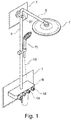
- a shower arrangement attached to an installation wall 1 is shown.
- the shower arrangement has a vertical shower rail 3 and a shower arm 5 adjoining it at the top, which ends at its free end with an overhead shower 7.
- the overhead shower 7 is in flow connection with an shower fitting 9 via an internal water supply of the shower arm 5 and the shower bar 3.
- the shower fitting 9 can be used to set the temperature and / or the amount of the mixed water flowing to the overhead shower 7.
- a hand shower 11 is shown height-adjustable on the shower rail 3 and is in flow connection with the shower fitting 9 via an indicated hose 13.
- the shower fitting 9 points in the Fig. 1 furthermore, two setting elements 14, by means of which a shower head spray type can be set.
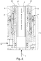
- an in Fig. 2 Indicated mixed water outlet 15 of a mixer tap arranged in the shower fitting 9 via two mixed water flow paths I, II separated from one another in terms of flow technology, with a first shower head jet outlet 17 ( Fig. 4 ) and / or with a second shower head jet outlet 19 ( Fig. 4 ) connectable.
- the two shower head jet outlets 17, 19 are in the Fig. 4 only roughly indicated schematically and have different water outlet possibilities from one another in order to provide different types of spray heads.
- the first and / or the second mixed water flow path I, II can be opened and / or closed in such a way that the mixed water flows out via the first and / or the second shower head jet outlet 17, 19.
- a main aspect of the invention relates to the implementation of the two mixed water flow paths I and II between the shower fitting 9 and the overhead shower outlet side: consequently, the internal water routing of the shower arm 5 and the shower bar 3 has an inner hose 21, which is loose inside the shower arm 5 and the shower rail 3 is laid up to the overhead shower 7 and which provides the first mixed water flow path I.
- the second mixed water flow path II is guided through an annular channel 23 which is delimited by the inner hose 21 and by the inside of the shower arm 5 or the shower bar 3.
- the shower arrangement is fastened to the installation wall 1 via a wall fastening 25.
- a vertical leg 27 of the shower arm 5 and an upper end of the shower rail are each designed with the same diameter and the end faces of the wall mounting 25 are in a butt joint.
- the upper end of the shower rail 3 and the vertical leg 27 of the shower arm 5 are attached to an inner intermediate sleeve 29.
- the vertical leg 27 is in the Figure 3 attached to the intermediate sleeve 29 via a screw 31, while the shower rail 3 is soldered to the intermediate sleeve 29.
- the inner intermediate sleeve 29 is fixed via fastening elements 33 within the wall fastening 25.
- a mixed water outlet 15 of the shower fitting 9 is indicated. Accordingly, the mixed water outlet 15 can be connected to both the annular channel 23 and the inner hose 21 in terms of flow, depending on the actuation of the first or the second adjusting element 14, so that one adjusting element 14 is provided for each mixed water flow path I, II.
- the shower head 7 has a shower head connector 35.
- the shower connector 35 is formed with an inlet-side, horizontal pipe socket 37 which merges into an outlet-side, vertical pipe socket 39, on which a distributor body 41 of the shower head housing 43 is held by means of a fastening screw 45.
- the inlet-side, horizontal pipe socket 37 of the shower head connector 35 is in the Fig. 4 in a liquid-tight plug connection with a free pipe end of the shower arm 5.
- a hose end of the inner hose 21 is loosely inserted into the horizontal inlet-side pipe socket 37 of the shower head connector 35 and with a pipe bend 47 extended.
- the pipe elbow 47 acts as a hose securing element, which holds the inner hose 21, which is otherwise loosely laid through the shower rail 3 and the shower arm 5, in a positionally secure manner, in particular during assembly / disassembly of the shower head 7.
- the pipe elbow 47 engages around one of the two pipe sockets 37, 39 spanned inside corner area of the shower head connector 35 and protrudes with a vertical elbow section 49 into the outlet-side, vertical pipe socket 39 of the shower head connector 35.
- the elbow 47 is integrally formed on the hose end of the inner hose 21 as a separate component, for example via an adhesive and / or welded connection. Both the elbow 47 and the inner tube 21 are in the Fig. 4 while maintaining a radially outer flow gap 51 positioned within the shower head connector 35.
- the second mixed water flow path II is optionally passed through the flow gap 51, as in FIG Fig. 4 is indicated.
- the flow gap 51 is designed as an annular gap which surrounds the vertical elbow section 49.
- the vertical elbow portion 49 of the elbow 47 is in the Fig. 4 connected to a connecting piece 53 of the distributor body 41 and connected to the first shower head jet outlet 17 via a first flow channel 55 formed in the distributor body 41.
- the annular flow gap 51 is also connected to the second shower head jet outlet 19 via a second flow channel 57 formed in the distributor body 41.
- hose securing element 47 is no longer designed as a pipe bend, but rather as a sleeve-shaped plastic end piece which is integrally formed on the hose end of the inner hose 21 in one piece and in one piece.
- annular groove 46 is formed as a positive-locking contour, into which a counter-contour 50 formed on the distributor body 41 engages.
Landscapes
- Health & Medical Sciences (AREA)
- Life Sciences & Earth Sciences (AREA)
- Engineering & Computer Science (AREA)
- Hydrology & Water Resources (AREA)
- Public Health (AREA)
- Water Supply & Treatment (AREA)
- Bathtubs, Showers, And Their Attachments (AREA)
- Nozzles (AREA)
Description
- Die Erfindung betrifft eine Duschanordnung nach dem Oberbegriff des Anspruches 1. Eine solche Duschanordnung ist bekannt aus der Druckschrift
CN102283602 . - Eine solche Duschanordnung weist eine in der Installationslage wandmontierte, vertikale Brausestange auf, an deren oberen Ende sich ein im Wesentlichen horizontaler Brausearm anschließt. Der Brausearm trägt an seinem freien, wandfernen Ende eine Kopfbrause.
- Aus der
DE 10 2005 004 788 A1 oder aus derDE 10 2012 008 406 A1 ist eine solche gattungsgemäße Duschanordnung bekannt. Deren Kopfbrause ist über eine innenliegende Wasserführung des Brausearms und der Brausestange mit einer Duscharmatur in Strömungsverbindung, mittels der die Temperatur und/oder die Menge des zur Kopfbrause geführten Mischwassers einstellbar sind. - Bei einer derartigen Duschanordnung kann in einer höheren Komfortklasse an der Duscharmatur ein Bedienfeld mit einem Taster zur Einstellung einer Brausekopf-Strahlart bereitgestellt sein, mit dem beim Duschvorgang in beliebiger Weise zumindest zwei unterschiedliche Brausestrahlarten miteinander und/oder getrennt voneinander anwendbar sind. Zur Realisierung einer solchen Strahlart-Einstellung ist der Mischwasser-Auslass der Duscharmatur über zumindest zwei voneinander getrennte Mischwasser-Strömungswege mit einem ersten Brausekopf-Strahlaustritt und mit einem zweiten Brausekopf-Strahlaustritt verbindbar.
- Diese beiden Mischwasser-Strömungswege zwischen der Duscharmatur und dem Brausekopf sind mit einem im Vergleich zu einem herkömmlichen Duschsystem erhöhten Installationsaufwand sowie Bauraumbedarf verknüpft. Weitere Duschanordnungen sind aus den Druckschriften
US2010/276020A1 undWO2005/031073A1 bekannt. - Die Aufgabe der Erfindung besteht darin, eine Duschanordnung bereitzustellen, die im Vergleich zum Stand der Technik einen reduzierten Installationsaufwand sowie einen reduzierten Bauraumbedarf ermöglicht.
- Die Aufgabe ist durch die Merkmale des Anspruches 1 gelöst. Bevorzugte Weiterbildungen der Erfindung sind in den Unteransprüchen offenbart.
- Gemäß dem Anspruch 1 ist die innenliegende Wasserführung des Brausearms sowie der Brausestange durch zwei Mischwasser-Strömungswege realisiert, die voneinander komplett strömungstechnisch entkoppelt sind. Ein erster Mischwasser-Strömungsweg ist als ein Innenschlauch ausgebildet, der innerhalb des Brausearms sowie der Brausestange bis zur Kopfbrause verläuft. Der zweite Mischwasser-Strömungsweg ist bauraumgünstig als ein Ringkanal zwischen dem Innenschlauch und dem radial äußeren Brausearm bzw. der Brausestange ausgebildet.
- Eine solche innenliegende Wasserführung ist insbesondere zur Einstellung unterschiedlicher Brausekopf-Strahlarten nutzbar, bei der der erste Mischwasser-Strömungsweg mit einem ersten Brausekopf-Strahlaustritt verbindbar ist und der zweite Mischwasser-Strömungsweg mit einem zweiten Brausekopf-Strahlaustritt verbindbar ist. In einem solchen Fall kann die Duscharmatur ein Strahlart-Einstellelement aufweisen, mittels dem der erste und/oder der zweite Mischwasser-Strömungsweg zum jeweils zugeordneten Brausekopf-Strahlaustritt freigebbar oder schließbar ist.
- Der Brausekopf weist ein Brausekopf-Anschlussstück auf, das speziell an die oben definierte innenliegende Wasserführung angepasst ist. Das Brauenschlussstück weist einen einlassseitigen, horizontalen Rohrstutzen auf, der in einen auslassseitigen, vertikalen Rohrstutzen übergeht, an dem ein Brausekopf-Gehäuse gehaltert ist, aus dem das Mischwasser in einer ersten und/oder zweiten Strahlart austritt. Der einlassseitige, horizontale Rohrstutzen des Brausekopf-Anschlussstückes ist in einer flüssigkeitsdichten Steckverbindung mit einem Rohrende des Brausearms . Demgegenüber kann der innerhalb des Brausearms verlegte Innenschlauch mit seinem Schlauchende lose in den horizontalen einlassseitigen Rohrstutzen des Brausekopf-Anschlussstückes eingeführt sein. Das Schlauchende des Innenschlauches kann mit einem Rohrkrümmer verlängert sein, dessen vertikaler Krümmerabschnitt in den auslassseitigen, vertikalen Rohrstutzen des Brausekopf-Anschlussstückes lose einragen kann.
- Der oben definierte Rohrkrümmer ist insbesondere bei der Montage/Demontage des Brausekopfes von besonderer Bedeutung. Der Rohrkrümmer wirkt nämlich als ein Schlauchsicherungselement, mit dem der Innenschlauch formschlüssig im Brausekopf-Anschlussstück gehaltert ist. Auf diese Weise ist gewährleistet, dass der ansonsten lose durch die Brausestange und durch den Brausearm verlegte Innenschlauch lagesicher positioniert ist, und zwar insbesondere während einer Montage/Demontage des Brausekopfes. Für eine solche Lagesicherung kann der Rohrkrümmer mit seinem vertikalen Krümmerabschnitt in den auslassseitigen, vertikalen Rohrstutzen des Brausekopf-Anschlussstückes einragen. Der Rohrkrümmer ist dabei bevorzugt querschnittsgrößer als der Innenquerschnitt des einlassseitigen, horizontalen Rohrstutzens des Brausekopf-Anschlussstückes ausgelegt.
- Das Schlauchsicherungselement ist ein hülsenförmiges Schlauch-Endstück, das am Außenumfang eine Formschlusskontur, z.B. eine Ringnut, aufweisen kann. Die außenumfangsseitige Formschlusskontur des hülsenförmigen Endstückes kann in der Zusammenbaulage in formschlüssiger Verbindung mit einer Gegenkontur im Brausekopf-Anschlussstück sein. Montagetechnisch bevorzugt ist es, wenn die Gegenkontur, separat von dem Brausekopf-Anschlussstück, an einem Verteilerkörper des Brausekopf-Gehäuses ausgebildet ist, das z.B. in einer flüssigkeitsdichten Steckverbindung mit dem Brausekopf-Anschlussstück bringbar ist.
- Das Schlauchsicherungselement und/oder der Innenschlauch können bevorzugt lose innerhalb des Brausekopf-Anschlussstückes positioniert sein. Zudem können sowohl das Schlauchsicherungselement als auch der Innenschlauch so im Brausekopf-Anschlussstück angeordnet sein, dass ein radial äußerer Strömungsspalt gebildet ist, durch den der zweite Mischwasser-Strömungsweg geführt ist, während der erste Mischwasser-Strömungsweg durch den Innenschlauch sowie den Rohrkrümmer führt.
- Der im Brausekopf-Anschlussstück ausgebildete Strömungsspalt kann über einen zweiten Strömungskanal mit dem zweiten Brausekopf-Strahlaustritt strömungstechnisch verbunden sein. Davon entkoppelt kann der am Innenschlauch angeschlossene Rohrkrümmer an seinem vertikalen Krümmerabschnitt an einem ersten Strömungskanal angebunden sein, der zum ersten Brausekopfstrahlaustritt führt. Sowohl der erste als auch der zweite Strömungskanal können gemeinsam in einem Verteilerkörper des Brausekopf-Gehäuses ausgebildet sein.
Nachfolgend ist ein Ausführungsbeispiel der Erfindung anhand der beigefügten Figuren beschrieben. - Es zeigen:
- Fig. 1
- in einer Seitenansicht eine an einer Installationswand installierte Duschanordnung;
- Fig. 2 bis 4
- jeweils vergrößerte Seitenschnittdarstellungen eines Mischwasserauslasses der Duscharmatur (
Fig. 2 ), einer Wandbefestigung (Fig. 3 ) und eines Brausekopfes (Fig. 4 ); und - Fig. 5
- in einer Ansicht entsprechend der
Fig. 4 ein zweites Ausführungsbeispiel. - In der
Fig. 1 ist eine an einer Installationswand 1 befestigte Duschanordnung gezeigt. Die Duschanordnung weist eine vertikale Brausestange 3 sowie einen daran nach oben anschließenden Brausearm 5 auf, der an seinem freien Ende mit einer Kopfbrause 7 abschließt. Die Kopfbrause 7 ist über eine innenliegende Wasserführung des Brausearms 5 und der Brausestange 3 mit einer Duscharmatur 9 in Strömungsverbindung. Mittels der Duscharmatur 9 kann in gängiger Praxis die Temperatur und/oder die Menge des zur Kopfbrause 7 strömenden Mischwassers eingestellt werden. Zudem ist in derFig. 1 eine an der Brausestange 3 höhenverstellbar gehalterte Handbrause 11 gezeigt, die über einen angedeuteten Schlauch 13 mit der Duscharmatur 9 in Strömungsverbindung ist. Die Duscharmatur 9 weist in derFig. 1 ferner zwei Einstellelemente 14 auf, mittels denen eine Brausekopf-Strahlart einstellbar ist. - Zur Realisierung einer solchen Strahlart-Einstellung ist ein in der
Fig. 2 angedeuteter Mischwasser-Auslass 15 einer in der Duscharmatur 9 angeordneten Mischbatterie über zwei voneinander strömungstechnisch getrennte Mischwasser-Strömungswege I, II mit einem ersten Brausekopf-Strahlaustritt 17 (Fig. 4 ) und/oder mit einem zweiten Brausekopf-Strahlaustritt 19 (Fig. 4 ) verbindbar. Die beiden Brausekopf-Strahlaustritte 17, 19 sind in derFig. 4 nur grob schematisch angedeutet und weisen voneinander unterschiedliche Wasseraustrittsmöglichkeiten auf, um unterschiedliche Brausekopf-Strahlarten bereitzustellen. Durch Betätigung des ersten oder zweiten Einstellelements 14 kann der erste und/oder der zweite Mischwasser-Strömungsweg I, II derart freigegeben und/oder geschlossen werden, dass das Mischwasser über den ersten und/oder den zweiten Brausekopf-Strahlaustritt 17, 19 ausströmt. - Ein Hauptaspekt der Erfindung betrifft die Realisierung der beiden Mischwasser-Strömungswege I und II zwischen der Duscharmatur 9 und der Kopfbrausen-Austrittsseite: Demzufolge weist die innenliegende Wasserführung des Brausearms 5 und der Brausestange 3 einen Innenschlauch 21 auf, der lose innerhalb des Brausearms 5 und der Brausestange 3 bis zur Kopfbrause 7 verlegt ist und der den ersten Mischwasser-Strömungsweg I bereitstellt. Der zweite Mischwasser-Strömungsweg II ist durch einen Ringkanal 23 geführt, der vom Innenschlauch 21 und von der Innenseite des Brausearms 5 bzw. der Brausestange 3 begrenzt ist.
- Wie aus der
Fig. 1 oder derFig. 3 hervorgeht, ist die Duschanordnung über eine Wandbefestigung 25 an der Installationswand 1 befestigt. Gemäß derFig. 3 sind ein vertikaler Schenkel 27 des Brausearms 5 und ein oberes Brausestangen-Ende jeweils durchmessergleich ausgelegt und sind deren Stirnseiten innerhalb der Wandbefestigung 25 in einer Stoßverbindung. Das obere Ende der Brausestange 3 sowie der vertikale Schenkel 27 des Brausearms 5 sind auf eine innenliegende Zwischenhülse 29 aufgesteckt. Der vertikale Schenkel 27 ist in derFigur 3 über eine Schraube 31 an der Zwischenhülse 29 befestigt, während die Brausestange 3 mit der Zwischenhülse 29 verlötet ist. Zudem ist die innenliegende Zwischenhülse 29 über Befestigungselemente 33 innerhalb der Wandbefestigung 25 festgelegt. - In der
Fig. 2 ist ein Mischwasser-Auslass 15 der Duscharmatur 9 angedeutet. Demzufolge ist der Mischwasser-Auslass 15 sowohl mit dem Ringkanal 23 als auch mit dem Innenschlauch 21 strömungstechnisch verbindbar, und zwar je nach Betätigung des ersten oder des zweiten Einstellelementes 14, so dass jeweils ein Einstellelement 14 pro Mischwasser-Strömungsweg I,II vorgesehen ist. - Nachfolgend wird anhand der
Fig. 4 der Anschluss der beiden Mischwasser-Strömungswege I, II an den Brausekopf 7 beschrieben: Demzufolge weist der Brausekopf 7 ein Brausekopf-Anschlussstück 35 auf. Das Brause-Anschlussstück 35 ist mit einem einlassseitigen, horizontalen Rohrstutzen 37 ausgebildet, der in einen auslassseitigen, vertikalen Rohrstutzen 39 übergeht, an dem ein Verteilerkörper 41 des Brausekopf-Gehäuses 43 über eine Befestigungsschraube 45 gehaltert ist. Der einlassseitige, horizontale Rohrstutzen 37 des Brausekopf-Anschlussstückes 35 ist in derFig. 4 in einer flüssigkeitsdichten Steckverbindung mit einem freien Rohrende des Brausearms 5. Ein Schlauchende des Innenschlauches 21 ist lose in den horizontalen einlassseitigen Rohrstutzen 37 des Brausekopf-Anschlussstückes 35 eingeführt und mit einem Rohrkrümmer 47 verlängert. Der Rohrkrümmer 47 wirkt als ein Schlauchsicherungselement, das den ansonsten lose durch die Brausestange 3 und den Brausearm 5 verlegten Innenschlauch 21 lagesicher hält, und zwar insbesondere während einer Montage/Demontage des Brausekopfes 7. Hierzu umgreift der Rohrkrümmer 47 einen von den beiden Rohrstutzen 37, 39 aufgespannten Inneneckbereich des Brausekopf-Anschlussstückes 35 und ragt mit einem vertikalen Krümmerabschnitt 49 in den auslassseitigen, vertikalen Rohrstutzen 39 des Brausekopf-Anschlussstückes 35 ein. - In der
Fig. 4 ist der Rohrkrümmer 47 als ein separates Bauteil zum Beispiel über eine Kleb- und/oder Schweißverbindung einstückig am Schlauchende des Innenschlauches 21 angeformt. Sowohl der Rohrkrümmer 47 als auch der Innenschlauch 21 sind in derFig. 4 unter Aufrechterhaltung eines radial äußeren Strömungsspaltes 51 innerhalb des Brausekopf-Anschlussstückes 35 positioniert. Durch den Strömungsspalt 51 wird gegebenenfalls der zweite Mischwasser-Strömungsweg II geführt, wie es in derFig. 4 angedeutet ist. In derFig. 4 ist der Strömungsspalt 51 als ein Ringspalt ausgeführt, der den vertikalen Krümmerabschnitt 49 umgibt. Der vertikale Krümmerabschnitt 49 des Rohrkrümmers 47 ist in derFig. 4 an einem Anschlussstutzen 53 des Verteilerkörpers 41 angeschlossen und über einen ersten, im Verteilerkörper 41 ausgebildeten Strömungskanal 55 mit dem ersten Brausekopf-Strahlaustritt 17 verbunden. In gleicher Weise ist auch der ringförmige Strömungsspalt 51 über einen zweiten, im Verteilerkörper 41 ausgebildeten Strömungskanal 57 mit dem zweiten Brausekopf-Strahlaustritt 19 verbunden. - In der
Figur 5 ist ein zweites Ausführungsbeispiel gezeigt, das weitgehend baugleich wie der in derFigur 4 gezeigte Brausekopf-Anschluss ist. Von daher wird sich auf die Vorbeschreibung bezogen. Im Unterschied zurFigur 4 ist in derFigur 5 das Schlauchsicherungselement 47 nicht mehr als ein Rohrkrümmer ausgeführt, sondern als ein hülsenförmiges Kunststoff-Endstück, das materialeinheitlich sowie einstückig am Schlauchende des Innenschlauches 21 angeformt ist. - Am Außenumfang des hülsenförmigen Kunststoff-Endstückes 47 ist als Formschlusskontur eine Ringnut 46 ausgebildet, in die eine am Verteilerkörper 41 angeformte Gegenkontur 50 eingreift. Somit erfolgt mit der Montage des Verteilungskörpers 41 am Brausekopf-Anschlussstück 35 automatisch eine Lagesicherung des Schlauchende des Innenschlauches 21 am Brausekopf-Anschlussstück 35.
-
- 1
- Installationswand
- 3
- Brausestange
- 5
- Brausearm
- 7
- Kopfbrause
- 9
- Duscharmatur
- 11
- Handbrause
- 13
- Schlauch
- 14
- Einstellelement
- 15
- Mischwasser-Auslass der Duscharmatur
- 17
- erster Brausekopf-Strahlaustritt
- 19
- zweiter Brausekopf-Strahlaustritt
- 21
- Innenschlauch
- 23
- Ringkanal
- 25
- Wandbefestigung
- 27
- vertikaler Schenkel des Brausearms 5
- 29
- innenliegende Zwischenhülse
- 31
- Schraube
- 33
- Befestigungselemente
- 35
- Brausekopf-Anschlussstück
- 37
- horizontaler Rohrstutzen
- 39
- vertikaler Rohrstutzen
- 41
- Verteilerkörper
- 43
- Brausekopf-Gehäuse
- 45
- Befestigungsschraube
- 46
- Formschlusskontur
- 47
- Rohrkrümmer
- 48
- Inneneckbereich
- 49
- vertikaler Krümmerabschnitt
- 50
- Gegenkontur
- 51
- Strömungsspalt
- 53
- Anschlussstutzen
- 55
- erster Strömungskanal
- 57
- zweiter Strömungskanal
- I
- erster Mischwasser-Strömungsweg
- II
- zweiter Mischwasser-Strömungsweg
Claims (9)
- Duschanordnung mit einer in der Installationslage vertikalen Brausestange (3), die an ihrem oberen Ende in einen Brausearm (5) übergeht, der an seinem freien Ende mit einer Kopfbrause (7) abschließt, die über eine innenliegende Wasserführung des Brausearms (5) und der Brausestange (3) mit einer Duscharmatur (9) in Strömungsverbindung bringbar ist, mittels der die Temperatur und/oder Menge des zum Brausekopf (7) geführten Mischwassers einstellbar ist, wobei die innenliegende Wasserführung zumindest zwei Mischwasser-Strömungswege (I, II) aufweist, die zwischen der Duscharmatur (9) und dem Wasseraustritt der Kopfbrause (7) komplett voneinander strömungstechnisch entkoppelt sind, wobei der erste Mischwasser-Strömungsweg (I) als ein Innenschlauch (21) ausgebildet ist, der innerhalb des Brausearms (5) und der Brausestange (3) bis zur Kopfbrause (7) geführt ist, und der zweite Mischwasser-Strömungsweg (II) als ein Ringkanal (23) zwischen dem Innenschlauch (21) und dem Brausearm (5) oder der Brausestange (3) bis zur Kopfbrause (7) ausgebildet ist, dadurch gekennzeichnet, dass der Brausekopf (7) ein Brausekopf-Anschlussstück (35) mit einem einlassseitigen, horizontalen Rohrstutzen (37) aufweist, der in einen auslassseitigen, vertikalen Rohrstutzen (39) übergeht, an dem ein Gehäuse (43) des Brausekopfs (7) gehaltert ist, dass das Schlauchende des Innenschlauches (21) ein Schlauchsicherungselement (47) aufweist, das im Brausekopf-Anschlussstück (35) formschlüssig gehaltert ist, so dass das Schlauchsicherungselement (47) den ansonsten lose durch die Brausestange (3) und durch den Brausearm (5) verlegten Innenschlauch (21) lagesicher hält, dass der einlassseitige, horizontale Rohrstutzen (37) des Brausekopf-Anschlussstückes (35) in flüssigkeitsdichter Verbindung mit einem Rohrende des Brausearms (5) ist, und dass das Schlauchsicherungselement (47) ein hülsenförmiges Endstück ist, das am Außenumfang eine Formschlusskontur (46), insbesondere eine Ringnut, aufweist, die mit einer Gegenkontur (50) im Brausekopf-Anschlussstück (35) in Formschlussverbindung ist.
- Duschanordnung nach Anspruch 1, dadurch gekennzeichnet, dass zwischen dem Innenschlauch (21) und dem Brausearm (5) mehrere Ringkanäle ausgebildet sind, und dass insbesondere jedem der Ringkanäle jeweils ein separater Mischwasser-Strömungsweg zugeordnet ist.
- Duschanordnung nach Anspruch 1 oder 2, dadurch gekennzeichnet, dass zur Einstellung unterschiedlicher Brausekopf-Strahlarten der erste Mischwasser-Strömungsweg (I) mit einem ersten Strahlaustritt (17) im Brausekopf (7) verbunden ist, und der zweite Mischwasser-Strömungsweg (II) mit einem zweiten Strahlaustritt (19) im Brausekopf (7) verbunden ist.
- Duschanordnung nach Anspruch 3, dadurch gekennzeichnet, dass die Duscharmatur (9) ein Strahlart-Einstellelement (14) aufweist, mittels dem der erste und/oder zweite Mischwasserweg (I, II) zum zugeordneten Brausekopf-Strahlaustritt (17, 19) freigebbar ist oder schließbar ist.
- Duschanordnung nach Anspruch 1, , wobei die Verbindung als eine Lötverbindung realisiert ist, und wobei insbesondere ein Schlauchende des Innenschlauches (21) unter Aufrechterhaltung des radial äußeren Ringkanals (23) in den horizontalen einlassseitigen Rohrstutzen (37) des Brausekopf-Anschlussstückes (35) lose eingeführt ist, insbesondere während einer Montage/Demontage des Brausekopfes (7).
- Duschanordnung nach Anspruch 5, dadurch gekennzeichnet, dass das Schlauchsicherungselement (47) ein Rohrkrümmer (47) ist, dessen vertikaler Krümmerabschnitt (49) in den auslassseitigen, vertikalen Rohrstutzen (39) des Brausekopf-Anschlussstückes (35) einragt.
- Duschanordnung nach Anspruch 6, dadurch gekennzeichnet, dass die Gegenkontur (50) unabhängig von dem Brausekopf-Anschlussstück (35) an einem Verteilerkörper (41) des Brausekopf-Gehäuses (43) ausgebildet ist.
- Duschanordnung nach einem der vorstehenden Ansprüche, dadurch gekennzeichnet, dass das Schlauchsicherungselement (47) und/oder der Innenschlauch (21) unter Aufrechterhaltung eines radial äußeren Strömungsspalts (51) im Brausekopf-Anschlussstück (35) positioniert sind, durch den der zweite Mischwasser-Strömungsweg (II) geführt ist.
- Duschanordnung nach einem der vorstehenden Ansprüche, dadurch gekennzeichnet, dass der im Brausekopf-Anschlussstück (35) ausgebildete Strömungsspalt (51) über einen zweiten Strömungskanal (57) mit dem zweiten Brausekopf-Strahlaustritt (19) verbunden ist, und/oder dass der am Innenschlauch (21) angeschlossene Rohrkrümmer (47) über einen ersten Strömungskanal (55) mit dem ersten Brausekopf-Strahlaustritt (17) verbunden ist, und dass insbesondere der erste und der zweite Strömungskanal (55, 57) in einem Verteilerkörper (41) des Brausekopf-Gehäuses (43) ausgebildet sind.
Priority Applications (1)
| Application Number | Priority Date | Filing Date | Title |
|---|---|---|---|
| PL18211130T PL3495571T3 (pl) | 2017-12-08 | 2018-12-07 | Układ prysznicowy |
Applications Claiming Priority (1)
| Application Number | Priority Date | Filing Date | Title |
|---|---|---|---|
| DE102017129341.8A DE102017129341A1 (de) | 2017-12-08 | 2017-12-08 | Duschanordnung |
Publications (2)
| Publication Number | Publication Date |
|---|---|
| EP3495571A1 EP3495571A1 (de) | 2019-06-12 |
| EP3495571B1 true EP3495571B1 (de) | 2020-06-10 |
Family
ID=64661220
Family Applications (1)
| Application Number | Title | Priority Date | Filing Date |
|---|---|---|---|
| EP18211130.2A Active EP3495571B1 (de) | 2017-12-08 | 2018-12-07 | Duschanordnung |
Country Status (5)
| Country | Link |
|---|---|
| EP (1) | EP3495571B1 (de) |
| DE (1) | DE102017129341A1 (de) |
| DK (1) | DK3495571T3 (de) |
| ES (1) | ES2813275T3 (de) |
| PL (1) | PL3495571T3 (de) |
Families Citing this family (3)
| Publication number | Priority date | Publication date | Assignee | Title |
|---|---|---|---|---|
| GB2592216B (en) * | 2020-02-19 | 2022-02-16 | Kohler Mira Ltd | Shower head mounting |
| JP7508349B2 (ja) * | 2020-12-03 | 2024-07-01 | Sanei株式会社 | オーバーヘッドシャワー装置 |
| CN216094324U (zh) * | 2021-05-14 | 2022-03-22 | 九牧厨卫德国有限公司 | 一种顶喷花洒及淋浴设备 |
Family Cites Families (5)
| Publication number | Priority date | Publication date | Assignee | Title |
|---|---|---|---|---|
| ATE375420T1 (de) * | 2003-09-30 | 2007-10-15 | Crs Spa | Duschsäule |
| DE102005004788B4 (de) | 2005-02-01 | 2023-10-12 | Grohe Ag | Brausestange für Duscheinrichtungen |
| CN201537035U (zh) * | 2009-04-29 | 2010-08-04 | 伟美(厦门)淋浴设备有限公司 | 一种淋浴杆组 |
| CN102283602A (zh) * | 2011-07-28 | 2011-12-21 | 厦门三骏工贸有限公司 | 远端切换多功能顶喷淋浴柱 |
| DE102012008406A1 (de) | 2012-04-27 | 2013-10-31 | Grohe Ag | Wandbefestigung für ein Duschsystem |
-
2017
- 2017-12-08 DE DE102017129341.8A patent/DE102017129341A1/de not_active Withdrawn
-
2018
- 2018-12-07 ES ES18211130T patent/ES2813275T3/es active Active
- 2018-12-07 EP EP18211130.2A patent/EP3495571B1/de active Active
- 2018-12-07 PL PL18211130T patent/PL3495571T3/pl unknown
- 2018-12-07 DK DK18211130.2T patent/DK3495571T3/da active
Non-Patent Citations (1)
| Title |
|---|
| None * |
Also Published As
| Publication number | Publication date |
|---|---|
| ES2813275T3 (es) | 2021-03-23 |
| EP3495571A1 (de) | 2019-06-12 |
| DE102017129341A1 (de) | 2019-06-13 |
| DK3495571T3 (da) | 2020-08-24 |
| PL3495571T3 (pl) | 2020-11-16 |
Similar Documents
| Publication | Publication Date | Title |
|---|---|---|
| EP2957681B1 (de) | Sanitärarmatur mit innenschlauchanordnung | |
| EP2775042B1 (de) | Zuleitung zur Kopfdusche einer Dusche | |
| DE102012008406A1 (de) | Wandbefestigung für ein Duschsystem | |
| EP1944418A1 (de) | Wasserauslaufarmatur | |
| EP2564283B1 (de) | Sanitäre mischbatterie, insbesondere für eine brausevorrichtung | |
| DE3339849A1 (de) | Halterung fuer handbrausen | |
| EP3412195A1 (de) | Schlauchkupplung mit filtersieb | |
| DE102013003926A1 (de) | Sanitäres Einbauteil, Innenschlauchanordnung für eine Sanitärarmatur und Sanitärarmatur | |
| EP3495571A1 (de) | Duschanordnung | |
| DE102008031558A1 (de) | Kopf- oder Seitenbrause | |
| EP0386589B1 (de) | Wasserauslaufarmatur | |
| DE102015215865A1 (de) | Armatur mit Schnellbefestigungsvorrichtung | |
| DE10312854B4 (de) | Sanitäre Einsetzeinheit | |
| EP2139608B1 (de) | Spritzpistolen-leitungsverbindungsvorrichtung | |
| EP2196584A1 (de) | Verteiler für eine Wasserleitungsanlage | |
| EP3401451A1 (de) | Wandbefestigung für ein duschsystem | |
| DE102017129333A1 (de) | Sanitärarmatur | |
| EP0734508B1 (de) | Plattenradiator | |
| EP3061877B1 (de) | Sanitärarmatur mit einer mit einer klammer befestigten schlauchverbindung | |
| EP3055463B1 (de) | Vorrichtung zum anschluss von sanitärarmaturen | |
| EP3290600B1 (de) | Armatur zur bereitstellung eines ersten fluids und eines zweiten fluids und verfahren zur herstellung deren | |
| DE102005002627A1 (de) | Duscheinrichtung | |
| DE102005004788A1 (de) | Brausestange für Duscheinrichtungen | |
| AT401094B (de) | Bausatz von rohrförmigen armaturen für die wasserleitungs-, sanitär-, heizungs-, gasleitungstechnik u.dgl. | |
| DE102016208354A1 (de) | Filteranordnung |
Legal Events
| Date | Code | Title | Description |
|---|---|---|---|
| PUAI | Public reference made under article 153(3) epc to a published international application that has entered the european phase |
Free format text: ORIGINAL CODE: 0009012 |
|
| STAA | Information on the status of an ep patent application or granted ep patent |
Free format text: STATUS: THE APPLICATION HAS BEEN PUBLISHED |
|
| AK | Designated contracting states |
Kind code of ref document: A1 Designated state(s): AL AT BE BG CH CY CZ DE DK EE ES FI FR GB GR HR HU IE IS IT LI LT LU LV MC MK MT NL NO PL PT RO RS SE SI SK SM TR |
|
| AX | Request for extension of the european patent |
Extension state: BA ME |
|
| STAA | Information on the status of an ep patent application or granted ep patent |
Free format text: STATUS: REQUEST FOR EXAMINATION WAS MADE |
|
| 17P | Request for examination filed |
Effective date: 20191202 |
|
| RBV | Designated contracting states (corrected) |
Designated state(s): AL AT BE BG CH CY CZ DE DK EE ES FI FR GB GR HR HU IE IS IT LI LT LU LV MC MK MT NL NO PL PT RO RS SE SI SK SM TR |
|
| GRAP | Despatch of communication of intention to grant a patent |
Free format text: ORIGINAL CODE: EPIDOSNIGR1 |
|
| STAA | Information on the status of an ep patent application or granted ep patent |
Free format text: STATUS: GRANT OF PATENT IS INTENDED |
|
| GRAS | Grant fee paid |
Free format text: ORIGINAL CODE: EPIDOSNIGR3 |
|
| INTG | Intention to grant announced |
Effective date: 20200407 |
|
| GRAA | (expected) grant |
Free format text: ORIGINAL CODE: 0009210 |
|
| STAA | Information on the status of an ep patent application or granted ep patent |
Free format text: STATUS: THE PATENT HAS BEEN GRANTED |
|
| AK | Designated contracting states |
Kind code of ref document: B1 Designated state(s): AL AT BE BG CH CY CZ DE DK EE ES FI FR GB GR HR HU IE IS IT LI LT LU LV MC MK MT NL NO PL PT RO RS SE SI SK SM TR |
|
| REG | Reference to a national code |
Ref country code: GB Ref legal event code: FG4D Free format text: NOT ENGLISH |
|
| REG | Reference to a national code |
Ref country code: AT Ref legal event code: REF Ref document number: 1279305 Country of ref document: AT Kind code of ref document: T Effective date: 20200615 Ref country code: CH Ref legal event code: EP |
|
| REG | Reference to a national code |
Ref country code: DE Ref legal event code: R096 Ref document number: 502018001642 Country of ref document: DE |
|
| REG | Reference to a national code |
Ref country code: IE Ref legal event code: FG4D Free format text: LANGUAGE OF EP DOCUMENT: GERMAN |
|
| REG | Reference to a national code |
Ref country code: DK Ref legal event code: T3 Effective date: 20200817 |
|
| REG | Reference to a national code |
Ref country code: FI Ref legal event code: FGE |
|
| REG | Reference to a national code |
Ref country code: NL Ref legal event code: FP |
|
| REG | Reference to a national code |
Ref country code: SE Ref legal event code: TRGR |
|
| REG | Reference to a national code |
Ref country code: LT Ref legal event code: MG4D |
|
| PG25 | Lapsed in a contracting state [announced via postgrant information from national office to epo] |
Ref country code: LT Free format text: LAPSE BECAUSE OF FAILURE TO SUBMIT A TRANSLATION OF THE DESCRIPTION OR TO PAY THE FEE WITHIN THE PRESCRIBED TIME-LIMIT Effective date: 20200610 Ref country code: NO Free format text: LAPSE BECAUSE OF FAILURE TO SUBMIT A TRANSLATION OF THE DESCRIPTION OR TO PAY THE FEE WITHIN THE PRESCRIBED TIME-LIMIT Effective date: 20200910 Ref country code: GR Free format text: LAPSE BECAUSE OF FAILURE TO SUBMIT A TRANSLATION OF THE DESCRIPTION OR TO PAY THE FEE WITHIN THE PRESCRIBED TIME-LIMIT Effective date: 20200911 |
|
| PG25 | Lapsed in a contracting state [announced via postgrant information from national office to epo] |
Ref country code: LV Free format text: LAPSE BECAUSE OF FAILURE TO SUBMIT A TRANSLATION OF THE DESCRIPTION OR TO PAY THE FEE WITHIN THE PRESCRIBED TIME-LIMIT Effective date: 20200610 Ref country code: HR Free format text: LAPSE BECAUSE OF FAILURE TO SUBMIT A TRANSLATION OF THE DESCRIPTION OR TO PAY THE FEE WITHIN THE PRESCRIBED TIME-LIMIT Effective date: 20200610 Ref country code: RS Free format text: LAPSE BECAUSE OF FAILURE TO SUBMIT A TRANSLATION OF THE DESCRIPTION OR TO PAY THE FEE WITHIN THE PRESCRIBED TIME-LIMIT Effective date: 20200610 Ref country code: BG Free format text: LAPSE BECAUSE OF FAILURE TO SUBMIT A TRANSLATION OF THE DESCRIPTION OR TO PAY THE FEE WITHIN THE PRESCRIBED TIME-LIMIT Effective date: 20200910 |
|
| PG25 | Lapsed in a contracting state [announced via postgrant information from national office to epo] |
Ref country code: AL Free format text: LAPSE BECAUSE OF FAILURE TO SUBMIT A TRANSLATION OF THE DESCRIPTION OR TO PAY THE FEE WITHIN THE PRESCRIBED TIME-LIMIT Effective date: 20200610 |
|
| PG25 | Lapsed in a contracting state [announced via postgrant information from national office to epo] |
Ref country code: CZ Free format text: LAPSE BECAUSE OF FAILURE TO SUBMIT A TRANSLATION OF THE DESCRIPTION OR TO PAY THE FEE WITHIN THE PRESCRIBED TIME-LIMIT Effective date: 20200610 Ref country code: RO Free format text: LAPSE BECAUSE OF FAILURE TO SUBMIT A TRANSLATION OF THE DESCRIPTION OR TO PAY THE FEE WITHIN THE PRESCRIBED TIME-LIMIT Effective date: 20200610 Ref country code: SM Free format text: LAPSE BECAUSE OF FAILURE TO SUBMIT A TRANSLATION OF THE DESCRIPTION OR TO PAY THE FEE WITHIN THE PRESCRIBED TIME-LIMIT Effective date: 20200610 Ref country code: EE Free format text: LAPSE BECAUSE OF FAILURE TO SUBMIT A TRANSLATION OF THE DESCRIPTION OR TO PAY THE FEE WITHIN THE PRESCRIBED TIME-LIMIT Effective date: 20200610 Ref country code: PT Free format text: LAPSE BECAUSE OF FAILURE TO SUBMIT A TRANSLATION OF THE DESCRIPTION OR TO PAY THE FEE WITHIN THE PRESCRIBED TIME-LIMIT Effective date: 20201012 |
|
| PG25 | Lapsed in a contracting state [announced via postgrant information from national office to epo] |
Ref country code: IS Free format text: LAPSE BECAUSE OF FAILURE TO SUBMIT A TRANSLATION OF THE DESCRIPTION OR TO PAY THE FEE WITHIN THE PRESCRIBED TIME-LIMIT Effective date: 20201010 Ref country code: SK Free format text: LAPSE BECAUSE OF FAILURE TO SUBMIT A TRANSLATION OF THE DESCRIPTION OR TO PAY THE FEE WITHIN THE PRESCRIBED TIME-LIMIT Effective date: 20200610 |
|
| REG | Reference to a national code |
Ref country code: DE Ref legal event code: R097 Ref document number: 502018001642 Country of ref document: DE |
|
| REG | Reference to a national code |
Ref country code: ES Ref legal event code: FG2A Ref document number: 2813275 Country of ref document: ES Kind code of ref document: T3 Effective date: 20210323 |
|
| PLBE | No opposition filed within time limit |
Free format text: ORIGINAL CODE: 0009261 |
|
| STAA | Information on the status of an ep patent application or granted ep patent |
Free format text: STATUS: NO OPPOSITION FILED WITHIN TIME LIMIT |
|
| 26N | No opposition filed |
Effective date: 20210311 |
|
| PG25 | Lapsed in a contracting state [announced via postgrant information from national office to epo] |
Ref country code: SI Free format text: LAPSE BECAUSE OF FAILURE TO SUBMIT A TRANSLATION OF THE DESCRIPTION OR TO PAY THE FEE WITHIN THE PRESCRIBED TIME-LIMIT Effective date: 20200610 |
|
| PG25 | Lapsed in a contracting state [announced via postgrant information from national office to epo] |
Ref country code: MC Free format text: LAPSE BECAUSE OF FAILURE TO SUBMIT A TRANSLATION OF THE DESCRIPTION OR TO PAY THE FEE WITHIN THE PRESCRIBED TIME-LIMIT Effective date: 20200610 |
|
| REG | Reference to a national code |
Ref country code: BE Ref legal event code: MM Effective date: 20201231 |
|
| PG25 | Lapsed in a contracting state [announced via postgrant information from national office to epo] |
Ref country code: LU Free format text: LAPSE BECAUSE OF NON-PAYMENT OF DUE FEES Effective date: 20201207 Ref country code: IE Free format text: LAPSE BECAUSE OF NON-PAYMENT OF DUE FEES Effective date: 20201207 |
|
| PG25 | Lapsed in a contracting state [announced via postgrant information from national office to epo] |
Ref country code: TR Free format text: LAPSE BECAUSE OF FAILURE TO SUBMIT A TRANSLATION OF THE DESCRIPTION OR TO PAY THE FEE WITHIN THE PRESCRIBED TIME-LIMIT Effective date: 20200610 Ref country code: MT Free format text: LAPSE BECAUSE OF FAILURE TO SUBMIT A TRANSLATION OF THE DESCRIPTION OR TO PAY THE FEE WITHIN THE PRESCRIBED TIME-LIMIT Effective date: 20200610 Ref country code: CY Free format text: LAPSE BECAUSE OF FAILURE TO SUBMIT A TRANSLATION OF THE DESCRIPTION OR TO PAY THE FEE WITHIN THE PRESCRIBED TIME-LIMIT Effective date: 20200610 |
|
| PG25 | Lapsed in a contracting state [announced via postgrant information from national office to epo] |
Ref country code: MK Free format text: LAPSE BECAUSE OF FAILURE TO SUBMIT A TRANSLATION OF THE DESCRIPTION OR TO PAY THE FEE WITHIN THE PRESCRIBED TIME-LIMIT Effective date: 20200610 |
|
| PG25 | Lapsed in a contracting state [announced via postgrant information from national office to epo] |
Ref country code: BE Free format text: LAPSE BECAUSE OF NON-PAYMENT OF DUE FEES Effective date: 20201231 |
|
| P01 | Opt-out of the competence of the unified patent court (upc) registered |
Effective date: 20230526 |
|
| PGFP | Annual fee paid to national office [announced via postgrant information from national office to epo] |
Ref country code: SE Payment date: 20231220 Year of fee payment: 6 Ref country code: FI Payment date: 20231221 Year of fee payment: 6 Ref country code: DK Payment date: 20231227 Year of fee payment: 6 Ref country code: AT Payment date: 20231221 Year of fee payment: 6 |
|
| PGFP | Annual fee paid to national office [announced via postgrant information from national office to epo] |
Ref country code: PL Payment date: 20231124 Year of fee payment: 6 |
|
| PGFP | Annual fee paid to national office [announced via postgrant information from national office to epo] |
Ref country code: CH Payment date: 20240102 Year of fee payment: 6 |
|
| PG25 | Lapsed in a contracting state [announced via postgrant information from national office to epo] |
Ref country code: FI Free format text: LAPSE BECAUSE OF NON-PAYMENT OF DUE FEES Effective date: 20241207 |
|
| REG | Reference to a national code |
Ref country code: DK Ref legal event code: EBP Effective date: 20241231 |
|
| REG | Reference to a national code |
Ref country code: SE Ref legal event code: EUG |
|
| REG | Reference to a national code |
Ref country code: CH Ref legal event code: PL |
|
| REG | Reference to a national code |
Ref country code: AT Ref legal event code: MM01 Ref document number: 1279305 Country of ref document: AT Kind code of ref document: T Effective date: 20241207 |
|
| PG25 | Lapsed in a contracting state [announced via postgrant information from national office to epo] |
Ref country code: AT Free format text: LAPSE BECAUSE OF NON-PAYMENT OF DUE FEES Effective date: 20241207 |
|
| PG25 | Lapsed in a contracting state [announced via postgrant information from national office to epo] |
Ref country code: CH Free format text: LAPSE BECAUSE OF NON-PAYMENT OF DUE FEES Effective date: 20241231 |
|
| PGFP | Annual fee paid to national office [announced via postgrant information from national office to epo] |
Ref country code: DE Payment date: 20251126 Year of fee payment: 8 |
|
| PGFP | Annual fee paid to national office [announced via postgrant information from national office to epo] |
Ref country code: GB Payment date: 20251204 Year of fee payment: 8 |
|
| PG25 | Lapsed in a contracting state [announced via postgrant information from national office to epo] |
Ref country code: DK Free format text: LAPSE BECAUSE OF NON-PAYMENT OF DUE FEES Effective date: 20241231 |
|
| PGFP | Annual fee paid to national office [announced via postgrant information from national office to epo] |
Ref country code: IT Payment date: 20251204 Year of fee payment: 8 |
|
| PGFP | Annual fee paid to national office [announced via postgrant information from national office to epo] |
Ref country code: NL Payment date: 20251204 Year of fee payment: 8 Ref country code: FR Payment date: 20251204 Year of fee payment: 8 |
|
| PGFP | Annual fee paid to national office [announced via postgrant information from national office to epo] |
Ref country code: ES Payment date: 20260113 Year of fee payment: 8 |