EP3495565A1 - Unité de soupape, en particulier pour commander un bras articulé pourvu d'un outil - Google Patents
Unité de soupape, en particulier pour commander un bras articulé pourvu d'un outil Download PDFInfo
- Publication number
- EP3495565A1 EP3495565A1 EP17205561.8A EP17205561A EP3495565A1 EP 3495565 A1 EP3495565 A1 EP 3495565A1 EP 17205561 A EP17205561 A EP 17205561A EP 3495565 A1 EP3495565 A1 EP 3495565A1
- Authority
- EP
- European Patent Office
- Prior art keywords
- valve
- flow
- port
- distributor
- working
- Prior art date
- Legal status (The legal status is an assumption and is not a legal conclusion. Google has not performed a legal analysis and makes no representation as to the accuracy of the status listed.)
- Granted
Links
- 239000012530 fluid Substances 0.000 claims description 96
- 238000011144 upstream manufacturing Methods 0.000 claims description 54
- 230000001105 regulatory effect Effects 0.000 claims description 27
- 238000004891 communication Methods 0.000 claims description 13
- 238000009795 derivation Methods 0.000 claims description 13
- 230000009471 action Effects 0.000 description 21
- 238000000605 extraction Methods 0.000 description 5
- 238000010586 diagram Methods 0.000 description 4
- 230000000284 resting effect Effects 0.000 description 4
- 238000009420 retrofitting Methods 0.000 description 4
- 230000009467 reduction Effects 0.000 description 3
- 238000009825 accumulation Methods 0.000 description 2
- 230000008901 benefit Effects 0.000 description 2
- 238000010276 construction Methods 0.000 description 2
- 230000008878 coupling Effects 0.000 description 2
- 238000010168 coupling process Methods 0.000 description 2
- 238000005859 coupling reaction Methods 0.000 description 2
- 230000003247 decreasing effect Effects 0.000 description 2
- 230000000694 effects Effects 0.000 description 2
- 230000005284 excitation Effects 0.000 description 2
- 230000007717 exclusion Effects 0.000 description 2
- 230000010355 oscillation Effects 0.000 description 2
- 230000002035 prolonged effect Effects 0.000 description 2
- 238000009877 rendering Methods 0.000 description 2
- 230000000712 assembly Effects 0.000 description 1
- 238000000429 assembly Methods 0.000 description 1
- 230000000903 blocking effect Effects 0.000 description 1
- 230000001447 compensatory effect Effects 0.000 description 1
- 230000001276 controlling effect Effects 0.000 description 1
- 238000012937 correction Methods 0.000 description 1
- 238000013016 damping Methods 0.000 description 1
- 238000006073 displacement reaction Methods 0.000 description 1
- 238000009429 electrical wiring Methods 0.000 description 1
- 238000002955 isolation Methods 0.000 description 1
- 238000012423 maintenance Methods 0.000 description 1
- 238000004519 manufacturing process Methods 0.000 description 1
- 230000007246 mechanism Effects 0.000 description 1
- 229910052757 nitrogen Inorganic materials 0.000 description 1
- IJGRMHOSHXDMSA-UHFFFAOYSA-N nitrogen Substances N#N IJGRMHOSHXDMSA-UHFFFAOYSA-N 0.000 description 1
- 230000003534 oscillatory effect Effects 0.000 description 1
- 230000000750 progressive effect Effects 0.000 description 1
- 230000003068 static effect Effects 0.000 description 1
Images


Classifications
-
- E—FIXED CONSTRUCTIONS
- E02—HYDRAULIC ENGINEERING; FOUNDATIONS; SOIL SHIFTING
- E02F—DREDGING; SOIL-SHIFTING
- E02F3/00—Dredgers; Soil-shifting machines
- E02F3/04—Dredgers; Soil-shifting machines mechanically-driven
- E02F3/28—Dredgers; Soil-shifting machines mechanically-driven with digging tools mounted on a dipper- or bucket-arm, i.e. there is either one arm or a pair of arms, e.g. dippers, buckets
- E02F3/36—Component parts
- E02F3/42—Drives for dippers, buckets, dipper-arms or bucket-arms
- E02F3/43—Control of dipper or bucket position; Control of sequence of drive operations
- E02F3/431—Control of dipper or bucket position; Control of sequence of drive operations for bucket-arms, front-end loaders, dumpers or the like
- E02F3/432—Control of dipper or bucket position; Control of sequence of drive operations for bucket-arms, front-end loaders, dumpers or the like for keeping the bucket in a predetermined position or attitude
- E02F3/433—Control of dipper or bucket position; Control of sequence of drive operations for bucket-arms, front-end loaders, dumpers or the like for keeping the bucket in a predetermined position or attitude horizontal, e.g. self-levelling
-
- B—PERFORMING OPERATIONS; TRANSPORTING
- B66—HOISTING; LIFTING; HAULING
- B66F—HOISTING, LIFTING, HAULING OR PUSHING, NOT OTHERWISE PROVIDED FOR, e.g. DEVICES WHICH APPLY A LIFTING OR PUSHING FORCE DIRECTLY TO THE SURFACE OF A LOAD
- B66F11/00—Lifting devices specially adapted for particular uses not otherwise provided for
- B66F11/04—Lifting devices specially adapted for particular uses not otherwise provided for for movable platforms or cabins, e.g. on vehicles, permitting workmen to place themselves in any desired position for carrying out required operations
- B66F11/044—Working platforms suspended from booms
-
- B—PERFORMING OPERATIONS; TRANSPORTING
- B66—HOISTING; LIFTING; HAULING
- B66F—HOISTING, LIFTING, HAULING OR PUSHING, NOT OTHERWISE PROVIDED FOR, e.g. DEVICES WHICH APPLY A LIFTING OR PUSHING FORCE DIRECTLY TO THE SURFACE OF A LOAD
- B66F9/00—Devices for lifting or lowering bulky or heavy goods for loading or unloading purposes
- B66F9/06—Devices for lifting or lowering bulky or heavy goods for loading or unloading purposes movable, with their loads, on wheels or the like, e.g. fork-lift trucks
- B66F9/065—Devices for lifting or lowering bulky or heavy goods for loading or unloading purposes movable, with their loads, on wheels or the like, e.g. fork-lift trucks non-masted
-
- B—PERFORMING OPERATIONS; TRANSPORTING
- B66—HOISTING; LIFTING; HAULING
- B66F—HOISTING, LIFTING, HAULING OR PUSHING, NOT OTHERWISE PROVIDED FOR, e.g. DEVICES WHICH APPLY A LIFTING OR PUSHING FORCE DIRECTLY TO THE SURFACE OF A LOAD
- B66F9/00—Devices for lifting or lowering bulky or heavy goods for loading or unloading purposes
- B66F9/06—Devices for lifting or lowering bulky or heavy goods for loading or unloading purposes movable, with their loads, on wheels or the like, e.g. fork-lift trucks
- B66F9/075—Constructional features or details
- B66F9/20—Means for actuating or controlling masts, platforms, or forks
- B66F9/22—Hydraulic devices or systems
-
- E—FIXED CONSTRUCTIONS
- E02—HYDRAULIC ENGINEERING; FOUNDATIONS; SOIL SHIFTING
- E02F—DREDGING; SOIL-SHIFTING
- E02F3/00—Dredgers; Soil-shifting machines
- E02F3/04—Dredgers; Soil-shifting machines mechanically-driven
- E02F3/28—Dredgers; Soil-shifting machines mechanically-driven with digging tools mounted on a dipper- or bucket-arm, i.e. there is either one arm or a pair of arms, e.g. dippers, buckets
- E02F3/36—Component parts
- E02F3/42—Drives for dippers, buckets, dipper-arms or bucket-arms
- E02F3/43—Control of dipper or bucket position; Control of sequence of drive operations
- E02F3/435—Control of dipper or bucket position; Control of sequence of drive operations for dipper-arms, backhoes or the like
- E02F3/436—Control of dipper or bucket position; Control of sequence of drive operations for dipper-arms, backhoes or the like for keeping the dipper in the horizontal position, e.g. self-levelling
-
- E—FIXED CONSTRUCTIONS
- E02—HYDRAULIC ENGINEERING; FOUNDATIONS; SOIL SHIFTING
- E02F—DREDGING; SOIL-SHIFTING
- E02F9/00—Component parts of dredgers or soil-shifting machines, not restricted to one of the kinds covered by groups E02F3/00 - E02F7/00
- E02F9/20—Drives; Control devices
- E02F9/22—Hydraulic or pneumatic drives
- E02F9/2264—Arrangements or adaptations of elements for hydraulic drives
- E02F9/2267—Valves or distributors
-
- F—MECHANICAL ENGINEERING; LIGHTING; HEATING; WEAPONS; BLASTING
- F15—FLUID-PRESSURE ACTUATORS; HYDRAULICS OR PNEUMATICS IN GENERAL
- F15B—SYSTEMS ACTING BY MEANS OF FLUIDS IN GENERAL; FLUID-PRESSURE ACTUATORS, e.g. SERVOMOTORS; DETAILS OF FLUID-PRESSURE SYSTEMS, NOT OTHERWISE PROVIDED FOR
- F15B11/00—Servomotor systems without provision for follow-up action; Circuits therefor
- F15B11/16—Servomotor systems without provision for follow-up action; Circuits therefor with two or more servomotors
- F15B11/20—Servomotor systems without provision for follow-up action; Circuits therefor with two or more servomotors controlling several interacting or sequentially-operating members
- F15B11/205—Servomotor systems without provision for follow-up action; Circuits therefor with two or more servomotors controlling several interacting or sequentially-operating members the position of the actuator controlling the fluid flow to the subsequent actuator
-
- F—MECHANICAL ENGINEERING; LIGHTING; HEATING; WEAPONS; BLASTING
- F15—FLUID-PRESSURE ACTUATORS; HYDRAULICS OR PNEUMATICS IN GENERAL
- F15B—SYSTEMS ACTING BY MEANS OF FLUIDS IN GENERAL; FLUID-PRESSURE ACTUATORS, e.g. SERVOMOTORS; DETAILS OF FLUID-PRESSURE SYSTEMS, NOT OTHERWISE PROVIDED FOR
- F15B11/00—Servomotor systems without provision for follow-up action; Circuits therefor
- F15B11/16—Servomotor systems without provision for follow-up action; Circuits therefor with two or more servomotors
- F15B11/22—Synchronisation of the movement of two or more servomotors
-
- F—MECHANICAL ENGINEERING; LIGHTING; HEATING; WEAPONS; BLASTING
- F15—FLUID-PRESSURE ACTUATORS; HYDRAULICS OR PNEUMATICS IN GENERAL
- F15B—SYSTEMS ACTING BY MEANS OF FLUIDS IN GENERAL; FLUID-PRESSURE ACTUATORS, e.g. SERVOMOTORS; DETAILS OF FLUID-PRESSURE SYSTEMS, NOT OTHERWISE PROVIDED FOR
- F15B2211/00—Circuits for servomotor systems
- F15B2211/30—Directional control
- F15B2211/305—Directional control characterised by the type of valves
- F15B2211/3056—Assemblies of multiple valves
- F15B2211/30565—Assemblies of multiple valves having multiple valves for a single output member, e.g. for creating higher valve function by use of multiple valves like two 2/2-valves replacing a 5/3-valve
-
- F—MECHANICAL ENGINEERING; LIGHTING; HEATING; WEAPONS; BLASTING
- F15—FLUID-PRESSURE ACTUATORS; HYDRAULICS OR PNEUMATICS IN GENERAL
- F15B—SYSTEMS ACTING BY MEANS OF FLUIDS IN GENERAL; FLUID-PRESSURE ACTUATORS, e.g. SERVOMOTORS; DETAILS OF FLUID-PRESSURE SYSTEMS, NOT OTHERWISE PROVIDED FOR
- F15B2211/00—Circuits for servomotor systems
- F15B2211/30—Directional control
- F15B2211/305—Directional control characterised by the type of valves
- F15B2211/3056—Assemblies of multiple valves
- F15B2211/3059—Assemblies of multiple valves having multiple valves for multiple output members
-
- F—MECHANICAL ENGINEERING; LIGHTING; HEATING; WEAPONS; BLASTING
- F15—FLUID-PRESSURE ACTUATORS; HYDRAULICS OR PNEUMATICS IN GENERAL
- F15B—SYSTEMS ACTING BY MEANS OF FLUIDS IN GENERAL; FLUID-PRESSURE ACTUATORS, e.g. SERVOMOTORS; DETAILS OF FLUID-PRESSURE SYSTEMS, NOT OTHERWISE PROVIDED FOR
- F15B2211/00—Circuits for servomotor systems
- F15B2211/40—Flow control
- F15B2211/405—Flow control characterised by the type of flow control means or valve
- F15B2211/40523—Flow control characterised by the type of flow control means or valve with flow dividers
- F15B2211/4053—Flow control characterised by the type of flow control means or valve with flow dividers using valves
-
- F—MECHANICAL ENGINEERING; LIGHTING; HEATING; WEAPONS; BLASTING
- F15—FLUID-PRESSURE ACTUATORS; HYDRAULICS OR PNEUMATICS IN GENERAL
- F15B—SYSTEMS ACTING BY MEANS OF FLUIDS IN GENERAL; FLUID-PRESSURE ACTUATORS, e.g. SERVOMOTORS; DETAILS OF FLUID-PRESSURE SYSTEMS, NOT OTHERWISE PROVIDED FOR
- F15B2211/00—Circuits for servomotor systems
- F15B2211/40—Flow control
- F15B2211/415—Flow control characterised by the connections of the flow control means in the circuit
- F15B2211/41527—Flow control characterised by the connections of the flow control means in the circuit being connected to an output member and a directional control valve
- F15B2211/41545—Flow control characterised by the connections of the flow control means in the circuit being connected to an output member and a directional control valve being connected to multiple output members
-
- F—MECHANICAL ENGINEERING; LIGHTING; HEATING; WEAPONS; BLASTING
- F15—FLUID-PRESSURE ACTUATORS; HYDRAULICS OR PNEUMATICS IN GENERAL
- F15B—SYSTEMS ACTING BY MEANS OF FLUIDS IN GENERAL; FLUID-PRESSURE ACTUATORS, e.g. SERVOMOTORS; DETAILS OF FLUID-PRESSURE SYSTEMS, NOT OTHERWISE PROVIDED FOR
- F15B2211/00—Circuits for servomotor systems
- F15B2211/50—Pressure control
- F15B2211/505—Pressure control characterised by the type of pressure control means
- F15B2211/50509—Pressure control characterised by the type of pressure control means the pressure control means controlling a pressure upstream of the pressure control means
- F15B2211/50545—Pressure control characterised by the type of pressure control means the pressure control means controlling a pressure upstream of the pressure control means using braking valves to maintain a back pressure
-
- F—MECHANICAL ENGINEERING; LIGHTING; HEATING; WEAPONS; BLASTING
- F15—FLUID-PRESSURE ACTUATORS; HYDRAULICS OR PNEUMATICS IN GENERAL
- F15B—SYSTEMS ACTING BY MEANS OF FLUIDS IN GENERAL; FLUID-PRESSURE ACTUATORS, e.g. SERVOMOTORS; DETAILS OF FLUID-PRESSURE SYSTEMS, NOT OTHERWISE PROVIDED FOR
- F15B2211/00—Circuits for servomotor systems
- F15B2211/50—Pressure control
- F15B2211/505—Pressure control characterised by the type of pressure control means
- F15B2211/50563—Pressure control characterised by the type of pressure control means the pressure control means controlling a differential pressure
- F15B2211/50581—Pressure control characterised by the type of pressure control means the pressure control means controlling a differential pressure using counterbalance valves
-
- F—MECHANICAL ENGINEERING; LIGHTING; HEATING; WEAPONS; BLASTING
- F15—FLUID-PRESSURE ACTUATORS; HYDRAULICS OR PNEUMATICS IN GENERAL
- F15B—SYSTEMS ACTING BY MEANS OF FLUIDS IN GENERAL; FLUID-PRESSURE ACTUATORS, e.g. SERVOMOTORS; DETAILS OF FLUID-PRESSURE SYSTEMS, NOT OTHERWISE PROVIDED FOR
- F15B2211/00—Circuits for servomotor systems
- F15B2211/70—Output members, e.g. hydraulic motors or cylinders or control therefor
- F15B2211/705—Output members, e.g. hydraulic motors or cylinders or control therefor characterised by the type of output members or actuators
- F15B2211/7051—Linear output members
- F15B2211/7053—Double-acting output members
-
- F—MECHANICAL ENGINEERING; LIGHTING; HEATING; WEAPONS; BLASTING
- F15—FLUID-PRESSURE ACTUATORS; HYDRAULICS OR PNEUMATICS IN GENERAL
- F15B—SYSTEMS ACTING BY MEANS OF FLUIDS IN GENERAL; FLUID-PRESSURE ACTUATORS, e.g. SERVOMOTORS; DETAILS OF FLUID-PRESSURE SYSTEMS, NOT OTHERWISE PROVIDED FOR
- F15B2211/00—Circuits for servomotor systems
- F15B2211/70—Output members, e.g. hydraulic motors or cylinders or control therefor
- F15B2211/71—Multiple output members, e.g. multiple hydraulic motors or cylinders
- F15B2211/7114—Multiple output members, e.g. multiple hydraulic motors or cylinders with direct connection between the chambers of different actuators
- F15B2211/7121—Multiple output members, e.g. multiple hydraulic motors or cylinders with direct connection between the chambers of different actuators the chambers being connected in series
-
- F—MECHANICAL ENGINEERING; LIGHTING; HEATING; WEAPONS; BLASTING
- F15—FLUID-PRESSURE ACTUATORS; HYDRAULICS OR PNEUMATICS IN GENERAL
- F15B—SYSTEMS ACTING BY MEANS OF FLUIDS IN GENERAL; FLUID-PRESSURE ACTUATORS, e.g. SERVOMOTORS; DETAILS OF FLUID-PRESSURE SYSTEMS, NOT OTHERWISE PROVIDED FOR
- F15B2211/00—Circuits for servomotor systems
- F15B2211/70—Output members, e.g. hydraulic motors or cylinders or control therefor
- F15B2211/78—Control of multiple output members
- F15B2211/782—Concurrent control, e.g. synchronisation of two or more actuators
Definitions
- the present invention relates to valve units and hydraulic systems, in particular for control of articulated arms or booms that carry a tool, typically an end tool.
- the invention has been developed with specific reference to applications where the tool requires a self-levelling action to maintain a constant attitude with respect to the ground as the position of the articulated arm varies.
- the reference technological background of the invention forming the subject of the present disclosure is represented by devices that enable implementation of the so-called self-levelling function on a tool that is being carried - typically in an end position - by an articulated arm, in order to maintain the tool with a constant attitude with respect to the ground to prevent any unbalancing of the load or, in the case of aerial work platforms, of the operator who is present on the platform.
- the object of the present invention is to solve the technical problems mentioned above.
- the object of the present invention is to provide a valve unit and a hydraulic system for control of an articulated arm and to make available a self-levelling function for the tool that is connected to the articulated arm that will be adaptable to a wide range of applications and will enable performance of the articulated arm to be maintained unaltered with respect to a condition where the latter is driven in a traditional way, i.e., without a self-levelling function.
- a valve unit comprising:
- the object of the invention is moreover achieved by a hydraulic system according to Claim 10.
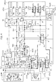
- the reference VU in Figure 1 denotes as a whole a valve unit according to a first embodiment of the invention.
- the valve unit VU comprises a first working port 1 and a second working port 2, which are configured for hydraulic connection to a first hydraulic distributor D1.
- the circuit VU includes a third working port 3 and a fourth working port 4, which are configured for hydraulic connection to a second hydraulic distributor identified by the reference D2.
- Each of the distributors D1, D2 is here schematically illustrated as a distributor with four ports (two upstream/source ports, two downstream/user-device ports) and three positions. The position on the left is a so-called parallel-flow position, the position on the right is a so-called cross-flow position, whilst the (centre) resting position is a closed-centre position for the ports 1 and 2 (and likewise for the ports 3 and 4) and a bypass-centre for the upstream ports.
- the reference numbers 5 and 6 designate, respectively, a fifth working port and a sixth working port of the valve unit VU, which are configured for connection to a respective fluid chamber of a first hydraulic actuator A1, in particular a linear actuator that can be driven by means of the distributor D1.
- the port 5 is connected to a fluid chamber (plunger side) that, when supplied, causes extraction of the stem of the actuator
- the port 6 is connected to a fluid chamber (stem side) that, when supplied, brings about retraction of the stem of the actuator.
- the reference numbers 7 and 8 designate, respectively, a seventh working port and an eighth working port of the valve unit VU, which are configured for connection to a respective fluid chamber of a second hydraulic actuator A2 that can be driven by said second hydraulic distributor D2.
- the actuator A2 is again a linear actuator, and the port 7 is connected to a fluid chamber (plunger side) that, when supplied, brings about extraction of the stem of the actuator, whereas the port 8 is connected to a fluid chamber (stem side) that, when supplied, brings about retraction of the stem of the actuator A2.
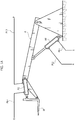
- Figure 1A is a schematic illustration of an articulated arm A, the (raising/lowering) movement of which is controlled by means of the actuator A1, which has a first end hinged to a fixed platform and a second end hinged to the arm A.
- a tool U (for example, a pair of forks) is set at the end of the arm A and is connected thereto in an articulated way.
- the movement of the joint, and hence the movement of the tool U with respect to the arm A is governed by means of the actuator A2, which has a first end hinged to the arm A and a second end hinged to the tool U in a point that creates a lever arm with respect to the articulation between the tool and the arm A (pitching movement of the tool).
- the reference numbers that are identical to the ones already adopted previously previously designate the same components that have already been described.
- the two actuators A1 and A2 can be driven each independently of the other, when this becomes necessary.
- a first power line PL1 connects the first working port 1 to the fifth working port 5, while a second power line PL2 connects the second working port 2 to the sixth working port 6.
- a third power line PL3 connects the third working port 3 to the seventh working port 7, while a fourth power line PL4 connects the fourth working port 4 to the eighth working port 8.
- power line used herein (with reference to the lines PL1, PL2, PL3, PL4) is borrowed from the terminology commonly used in the sector of hydraulics and pneumatics and indicates a hydraulic power line, which is configured for transfer of flow of working fluid (at a respective pressure) in the hydraulic circuit.
- power line is - as per convention - applied to distinguish this type of hydraulic line from so-called (hydraulic) "pilot lines”, which serve only to carry a signal (generally a pressure signal) for operating/piloting components of the hydraulic circuit.
- pilot lines do not generally have a function of transferring flow (on the other hand, the amount of fluid that is in a pilot line is very low as compared to the amount flowing in a power line), but merely have a function of transferring the (pressure) signal onto surfaces of influence of driving actuators or of moving elements of valves.
- the valve unit VU referred to above moreover includes a first flow regulating valve RQ1 and a second flow regulating valve RQ2, which are preferably identical.
- the first flow regulating valve RQ1 includes an inlet port connected to the aforesaid first power line PL1 at a first circuit node J1, and moreover includes a first outlet port RQ1A connected to said fourth power line at a second circuit node J2.
- the flow regulating valve RQ1 is a flow divider, and thus includes a second outlet port RQ1B, which is connected to the power line PL1 at a circuit node R1 upstream of the node J1 ("upstream" being understood with respect to the direction of reading of the circuit diagram, proceeding from the port 1 to the port 5; during operation, the direction of flow may in actual fact vary).
- flow regulating valves may be used, for example a flow regulating valve with two ports, with a pressure-limiting valve connected in derivation, or else a flow regulating valve with three ports.
- the flow divider splits the flow of incoming fluid into a priority flow that passes through the port RQ1A and an excess flow that passes through the port RQ1B and returns to the node R1.
- a first check valve NR1 Located upstream of the node J1, and in particular in a position such as to be downstream of the node R1 ("upstream” and “downstream” being understood as explained previously), the latter constituting the connection of the port RQ1B to the line PL1, is a first check valve NR1 designed to enable a flow of working fluid only towards the node J1.
- a second check valve NR2 is, instead, set on the line PL1 between the circuit node J1 and the fifth working port 5 and is designed to enable a flow of working fluid only towards the port 5.
- a first overcentre valve OVC1 Moreover set in parallel with the check valve NR2 is a first overcentre valve OVC1.
- the valve OVC1 is normally in a closed position and is driven into opening by the pressure that is exerted upon the working port 5 and by the pressure that is exerted upon the working port 6, in the latter case by means of a signal SOVC1*. It should be noted that the valve NR2 may form part of a single hydraulic component with the valve OVC1.
- the signal SOVC1* enables optimal control of opening of the overcentre valve OVC1; i.e., it enables control of opening thereof when there is effectively a supply of working fluid from the line P to the port 6 by way of the line PL2, and not under the action of a static load on the articulated arm that pressurises the chamber, plunger side (port 5).
- a first cut-off valve CV1 is set between the first outlet port RQ1A of the valve RQ1 and the node J2. Furthermore, set between the cut-off valve CV1 and the node J2 is a third check valve NR3 designed to enable a flow of working fluid only towards the node J2.
- the cut-off valve CV1 is preferably a valve with two ports and two positions (open/closed) with a two-way open position, where the resting position shown in Figure 1 is a free-flow position (open position), whereas the second operative position is a position with flow shut off (closed position).
- the valve CV1 is driven in closing, i.e., into the second operative position, by a pilot line SCV1, which transfers to the moving element of the valve CV1 a pressure signal corresponding to the pressure in the power line PL1, in particular on the working port 1.
- valve RQ2 in a way similar to the valve RQ1 on the line PL1, the valve RQ2 includes an inlet port connected to the second power line PL2 at a third circuit node J3, which is in fluid communication with the working port 6 and is set downstream of the working port 2 ("downstream" being understood as indicated above).
- the valve RQ2 moreover includes a first outlet port RQ2A, which is connected to the third power line PL3 at a fourth circuit node J4, where the node J4 is located downstream of the working port 3 ("downstream" being understood as indicated above).
- valve RQ2 is provided as a flow divider and thus includes a second outlet port RQ2B, which is connected to the power line PL2 at a circuit node R2 that is located upstream of the circuit node J3, between the working port 2 and the circuit node J3 itself ("upstream" being understood as indicated above).
- a fourth check valve NR4 which is moreover positioned downstream of the circuit node R2 ("downstream" being understood as indicated above), the latter constituting the connection of the port RQ2B to the line PL2 so as to be comprised between the nodes R2 and J3.
- the valve NR4 is configured for enabling a flow of fluid only towards the node J3.
- a second cut-off valve CV2 is set between the first outlet port RQ2A of the valve RQ2 and the circuit node J4, and has characteristics identical to the valve CV1: a first operative position of rest with (two-way) free flow (open position), illustrated in the figure, and a second operative position of work with the flow shut off (hence, it is a valve with two ports and two positions).
- the valve CV2 is driven in closing, i.e., into the second operative position, by means of a pilot signal SCV2 that transfers onto a surface of influence of the moving element of the valve CV2 a pressure signal corresponding to the pressure in the line PL2, in particular at the working port 2.
- a fifth check valve NR5 is set between the first outlet port RQ2A and the circuit node J4, and preferably between the valve CV2 and the node J4, and is configured for enabling a flow of working fluid only towards the node J4.
- a sixth check valve NR6 is set between the circuit node J4 and a fifth circuit node J5, which is directly in view of the working port 7.
- the valve NR6 is configured for enabling a flow of working fluid only towards the circuit node J5.
- a hydraulic return line set along which is a second overcentre valve OVC2, set upstream of which is the node J5 ("upstream” and “downstream” are here understood with reference to the only direction of flow of the working fluid through the overcentre valve) and set downstream of which is a ninth working port 9, which connects up directly to the discharge line T.
- a seventh check valve NR7 which is configured for enabling a flow of working fluid only towards a sixth circuit node J6, which is set immediately downstream of the valve NR7 ("downstream” being understood with reference to the only direction of flow allowed by the valve NR3).
- a return line set along which is a third overcentre valve OVC3, which connects up directly to a tenth working port 10, which is in turn connected to the discharge line T.
- the line PL4 moreover supplies a pilot signal SOVC2, which drives the overcentre valve 2 in opening, and is moreover connected to the discharge line T by means of a choke, which decouples the pressure level of the pilot signal SOVC2 from the pressure level that is exerted upon the discharge line T.
- the power line PL3 supplies a pilot signal SOVC3 for the valve OVC3, which drives the overcentre valve OVC3 in opening and is also connected to the discharge via interposition of a choke that decouples the pressure level of the pilot signal SOVC2 from the pressure level in the discharge line T.
- the signals SOVC2 and SOVC3 are received immediately downstream of the nodes J2 and J4, respectively.
- valve unit VU Operation of the valve unit VU, and in general of the hydraulic system that enables control of the articulated arm according to the invention, is described in what follows.
- the actuators A1 and A2 can be driven separately by means of the distributors D1 and D2 for governing the movements of raising and lowering of the articulated arm - actuator A1 - and the positive and negative movements of pitching of the tool, i.e., the positive or negative variations in attitude of the tool that is carried by the articulated arm - actuator A2.
- each driving action imparted on the actuator A1 via driving of the distributor D1 results in a compensatory driving action on the actuator A2 performed by the valve unit VU in order to keep the attitude of the tool of the articulated arm constant with respect to the ground, preventing any variations thereof.
- the port 1 is connected to the line P, and hence receives the working fluid directly from the pump PM.
- the pressurized working fluid then enters the power line PL1, traverses the node R1, the check valve NR1, which allows a direction of flow only towards the node J1 (and towards the port 5), and the node J1, and then passes beyond the overcentre valve OVC1 thanks to the check valve NR2, and directly reaches the port 5 and the chamber of the actuator A1, which, when supplied, brings about extraction of the stem.
- valve CV1 is switched into a closed position by means of the pilot signal SCV1, which reads the pressure of the working fluid in the power line PL1 (in particular, on the port 1), so that no part of the flow that traverses the line PL1 is diverted by the flow divider RQ1 towards the node J2 and towards the line PL4.
- the port 6 receives a flow of working fluid in the opposite direction, which enters the line PL2 and proceeds towards the circuit node J3, and corresponds to the working fluid discharged by the opposite chamber of the actuator A1, i.e., the chamber coming under which is the port 6.
- the pilot signal SCV2 is inactive, and the cut-off valve CV2 remains in an open position.
- the flow divider RQ2 consequently directs a priority share of the flow received from the chamber of the actuator A1 that is decreasing in volume (the chamber coming under which is the port 6) towards the line PL3, with passage through the port RQ2A.
- a secondary share of flow is, instead, emptied off through the port RQ2B and sent directly to the discharge through the line PL2.
- the working fluid After passing through the port RQ2A, the working fluid traverses the cut-off valve CV2 (which remains in an open position given that the pilot signal SCV2 reads and transfers thereto a pressure equal to the discharge pressure) and traverses the check valve NR5 to reach the node J4.
- the only direction possible for the working fluid is the power line PL3 downstream of the node J4, then the check valve NR6, and from there the node J5 and the working port 7, from which the working fluid enters the chamber (plunger side) of the actuator A2, to achieve a compensation in the direction of extraction of the stem.
- this corresponds to a counterclockwise rotation of the end tool, which ensures that the orientation parallel to the ground will be maintained.
- the overcentre valve OVC2 remains in a closed position so that the fluid that enters the node J5 cannot be sent directly to the discharge (it should be noted, in fact, that the driving signal SOVC2 reads the pressure signal from the line PL4, this signal being, however, substantially equal to the tank pressure in so far as the valves NR3 and CV1 isolate the node J2 from the line PL1 and the valve NR7 does not enable the fluid discharged from the port 8 to contribute to definition of the signal SOVC2).
- the fluid at output from the port 8 can only be sent towards the overcentre valve OVC3, which enables control of the pulling action exerted upon the end tool during the action of compensation.
- the overcentre valve OVC3 preferably has a calibration pressure of 200 bar and, once again preferably, is sized so as to have a driving ratio of 1:3 in order to ensure a more regular operation of the actuator A2 under the pulling load.
- the typical volume displacement of the actuator A2 and the section of the corresponding plunger are in general such that, under the most statistically frequent loads, the pressure in the discharge chamber rises considerably when the load is a pulling load (the area of the plunger is relatively small so that the chamber pressure is relatively high).
- the driving ratio is a ratio between the opening pressure and the calibration pressure/maximum pressure of the overcentre valve - opening occurs in a sharp and jerky way.
- the intervention carried out on the valve OVC 3 is typically that of adopting a stiffer pre-loading spring so as to increase the driving ratio according to the definition given above (if the reciprocal is used, the driving ratio is decreased).
- this corresponds to the position of cross flows of the distributor D1, where the port 2 is connected to the line P while the port 1 is connected to the discharge T.
- the working fluid processed by the pump PM is sent into the line PL2 through the port 2, traverses the junction R2 and the valve NR4, and reaches the node J3. From the node J3, the working fluid proceeds directly towards the port 6 and towards the chamber of the actuator A1, which, when supplied, causes retraction of the stem, while the fluid is substantially prevented from passing through the flow divider RQ2.
- the share that is sent to the actuator A2 is, as in the previous case, supplied by the chamber of the actuator A1 that is emptying, namely, the chamber that comes under the port 5. From here, the working fluid discharged first traverses the overcentre valve OVC1, necessary for control of the pulling load acting to bring about lowering of the articulated arm, and then passes through the line PL1 until it reaches the node J1.
- the working fluid is then prevented from proceeding through the valve NR1 and is consequently forced to enter the flow divider RQ1. From here, a priority share of flow is sent towards the port RQ1A and through the valve CV1, which, given the connection of the line PL1 to the discharge, has the pilot signal SCV1 inactive, and hence remains in an open position.
- the priority flow of working fluid traverses the valve NR3, then the node J2, and from this the valve NR7, the node J6, and the port 8, and enters the chamber (stem side) of the actuator A2, which thus retracts the stem.
- the closed-centre position of the distributor D2 prevents the flow of working fluid through the node J2 from being split, whilst the absence of pilot signal SOVC3 keeps the overcentre valve OVC3 in a closed position.
- the valve NR5 isolates the stretch of line PL3 upstream of the valve NR6 in such a way that the signal SOVC3 can only represent the pressure on the discharge line T.
- the overcentre valve OVC2 preferably has a calibration pressure of 200 bar, and, once again preferably, is sized so as to have a driving ratio 1:8 or 1:10 (in general from 1:8 to 1:10) in such a way that also with a pilot signal of low intensity (low pressure) the valve can be opened.
- valve OVC 1 In the case of the valve OVC 1, the pressure that is exerted upon the port 6 during lowering of the actuator is typically low on account of the marked pulling action due to the load that is exerted upon the actuator A1. If the driving ratio were higher, the valve OVC1 would not manage to open if not under impulsive actions (but at this point it would be an opening due to exceeding of the calibration pressure/maximum pressure).
- valve OVC2 For the valve OVC2, during normal operation controlled by the distributor D2, it regulates the flow at the discharge of the chamber leading to the port 7, the pilot signal coming from the port 8. Since the load in this case is a purely resistant load and not a pulling load, the valve OVC2 must open for low pressures in order to prevent any useless dissipation of energy (in brief, the resistant action of the overcentre valve OVC2 must not add to the resistance already offered by the load). Also on the hypothesis of pulling loads in the direction that causes retraction of the stem of the actuator A2, the opening pressure must in any case be low to prevent any blocking of the actuator itself (the pulling actions during retraction are physiologically of a modest degree, considering operation of the actuator A2).
- valve OVC2 is piloted by a pressure signal that is linked to the pressure that is exerted upon the port RQ1A: in that point, the pressure could be relatively low on account of the marked pressure drop induced by the overcentre valve OVC1 so that the pilot pressure could, in the final analysis, be relatively low.
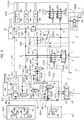
- FIG. 2 illustrates a different embodiment of the hydraulic system according to the invention, where accessory functional assemblies are provided, and where the unit VU is equipped, not only with the basic configuration that has already been described, but also with further valves to provide some accessory functions.
- the accessory components include:
- each of the distributors UT1, UT2, UT3 are connected to the upstream ports of the next distributor, thus substantially obtaining a continuity in the lines PL3 and PL4 that is functionally equivalent to the condition of Figure 1 .
- each of the distributors which can be activated by means of an electrical signal PA, PB, PC, enables the ports 3 and 4 to be set in communication, respectively, with the ports A and B of users UT1, UT2, UT3, denoted by the same references as the distributors, where each port A, B is associated to a prefix that consists of a U followed by the progressive number of each user.
- the valve unit VU is enriched, instead, with a fast-filling module FF, which facilitates filling of the chamber of the actuator A1 that will first be involved in a phenomenon of discharge of working fluid after a prolonged stoppage of the system, in particular a discharge to complete an action of compensation on the actuator A2.
- a fast-filling module FF which facilitates filling of the chamber of the actuator A1 that will first be involved in a phenomenon of discharge of working fluid after a prolonged stoppage of the system, in particular a discharge to complete an action of compensation on the actuator A2.
- the fast-filling assembly FF includes a third cut-off valve CV3 and a fourth cut-off valve CV4, which bridge the power lines PL1 and PL2.
- the cut-off valve CV3 is combined to an eighth check valve NR8 set in series to it on the side of the line PL2, whereas the valve CV4 is set in series to a ninth check valve NR9 set on the side of the line PL1.
- valve NR8 enables a flow of working fluid only from the line PL1 towards the line PL2 (after the fluid has passed through the valve CV3)
- valve NR9 enables a flow of working fluid only from the line PL2 towards the line PL1 (after the fluid has passed through the valve CV4).
- the working fluid that enters the line PL1 is blocked by the valve NR9 but can pass through the valve CV3 and the valve NR8, then traversing the line PL2, to enter the chamber (stem side) directly through the port 6 (the working fluid does not enter the flow divider in so far as it is a path with higher hydraulic resistance).
- the valve CV4 is at the same time forced to close by the pressure exerted upon the line PL1.
- valve CV3 Once filling of the chamber (stem side) is through, the pressure that is set up on the port 6 drives the valve CV3 into closing (signal SCV3), isolating the ports of the series of valves CV3 and NR8 and enabling movement of the working fluid in a way identical to what has been described previously.
- closing of the valve CV4 prevents in any case any passage of fluid towards the valve NR9, avoiding a hydraulic short-circuit (a phenomenon already in itself generally prevented by the fact that the pressure that is present in the line PL1 and that keeps the valve NR9 in a closed position is higher than the pressure that is present in the line PL2).
- the valve CV3 is at the same time driven into closing by the pressure that is present in the line PL2. Once filling of the chamber, plunger side, is completed, the pressure that is set up on the port 5 drives the valve CV4 into closing (signal SCV4), isolating the ports of the series of valves CV4 and NR9 and enabling movement of the working fluid in a way identical to what has been described previously.
- closing of the valve CV3 in any case prevents any passage of fluid towards the valve NR8, avoiding hydraulic short-circuit (a phenomenon already in itself generally prevented by the fact that the pressure that is present in the line PL1 and that keeps the valve NR9 in a closed position is higher than the pressure that is present in the line PL2).
- valve unit VU and the hydraulic system according to the invention enable an easy solution to the problems left unsolved by the prior art.
- the problem of reduction of performance of the actuator that governs the articulated arm is solved by the fact that there takes place a direct supply of the expanding chamber of the actuator A1, without passing through flow-splitting valves or flow regulating valves.
- the performance of the actuator A1 can be kept constant as compared to the case where it is controlled only by the distributor D1, without requiring replacement of the pump PM.
- valve unit VU possesses interfaces for connection to the other components of the hydraulic system that adapt completely to the most common hydraulic schemes of already existing vehicles, thus rendering it a natural candidate for on-vehicle retrofitting.
- valve unit VU is intrinsically suited to retrofitting or implementation on a vast range of different vehicles and on a vast range of different tools.
- the element that determines the behaviour of the valve unit VU, in particular as regards the action of compensation is the flow regulating valve RQ1, RQ2.
- the valves RQ1 and RQ2 are built as flow dividers, it is sufficient to vary calibration of the flow dividers themselves to vary splitting of the flow at inlet through the nodes J1 and J3 in order to vary the degree of the action of compensation.
- Figure 3 illustrates some possible variants of the flow regulating valve RQ1/RQ2 that can be used in a valve unit according to the invention.
- the references adopted that are identical to the ones already used in the description designate the same power ports. Appearing in brackets are the references that apply to the valve RQ2.
- Figure 3A illustrates a flow regulating valve RQ1/RQ2 obtained as distributor with three ports and two positions, electrically driven as a function of the pressure that is present in the line PL1, designated by p(PL1) (for the other branch of the circuit, the line is PL2 and the pressure is p(PL2)).
- the resting position corresponds to the same type of hydraulic connection implemented in the flow divider referred to in the diagrams of Figures 1 and 2
- the resulting position following upon electrical driving (switching) of the valve corresponds to a position where the port RQ1A (or RQ2A) is isolated, whereas the inlet port is in fluid communication with the port RQ2B.
- the cut-off valves CV1 and CV2 are no longer necessary in so far as their function is automatically performed at the moment of switching of the valve RQ1/RQ2.
- Figure 3B illustrates a variant of the valve RQ1/RQ2 of Figure 3A , where the position resulting from electrical control of the valve envisages isolation of all three working ports. For the rest, the description already presented for Figure 3A applies.
- FIG. 3C illustrates a valve RQ1/RQ2 obtained with an ensemble of a flow regulating valve with two ports R2W, connected to which, upstream and in derivation, is a pressure-limiting valve VL.
- the flow regulating valve with two ports R2W includes a choke with variable section set in series with, and upstream of, a normally open valve, the moving element of which is driven into closing by the pressure upstream of the choke and into opening by the pressure downstream of the choke.
- the moving element is moreover kept in an open position by means of an elastic element, to which there corresponds an equivalent calibration pressure that enables regulation of the value of flowrate of fluid discharged by the valve R2W. For this reason, provided upstream of the valve R2W is the inlet port of the valve RQ1/RQ2 (where the node J1/J3 is located), whereas provided downstream of the valve R2W is the port RQ1A/RQ2A.
- the port RQ1B/RQ2B is, instead, provided downstream of the pressure-limiting valve VL, which in this way is configured for disposing of the flow of working fluid that cannot be disposed of through the valve R2W.
- FIG. 3D illustrates a valve RQ1/RQ2 obtained by means of a flow regulating valve with three ports.
- the latter valve includes a choke with variable section (this being understood as component as such or as functional equivalent) connected to the inlet port of the valve RQ1/RQ2.
- a normally closed valve R3 Set in derivation upstream of the choke and downstream of the inlet port is a normally closed valve R3, the moving element of which is driven into opening by the pressure upstream of the choke (the pilot signal is preferably picked up also upstream of the derivation of the valve R3), whereas it is driven into closing by means of an elastic element and a pressure signal, which is picked up downstream of the choke with variable section.
- the port RQ1A/RQ2A Provided downstream of the choke with variable section is the port RQ1A/RQ2A, whereas provided downstream of the valve R3 is the port RQ1B/RQ2B.
- valves RQ1/RQ2 represented therein with the cut-off valves CV1 and CV"
- the hydraulic system as illustrated in Figures 4 and 6 includes the valve unit VU of Figure 2 , and differs from the scheme illustrated therein only as regards the structure and connections of the flow-deviation unit UTX.
- the flow-deviation unit is designated by the reference UTX1, and is split into in two sections, a first section UTX1D and a second section UTX1U (this applies also to the next Figure 6 ).
- the section UTX1D is connected in a position upstream of the valve unit VU, and in particular in a position hydraulically in series between the distributor D1 and the ports 1 and 2 (hence in series to the power lines PL1 and PL2).
- the section UTX1D includes the distributor UT1, which, as has already been described previously, takes the form of a distributor with six ports (two upstream and four downstream, where the terms “upstream” and “downstream” here refer to a concordant direction of flow through the lines 1 and 2 that originates from the distributor D1) and two positions.
- the upstream ports of the distributor UT1 are connected to the downstream ports of the distributor D1, whereas the downstream ports of the distributor UT1 are connected/connectable in pairs to the ports 1 and 2 of the valve unit VU (and to the power lines PL1, PL2, respectively) and to the power lines U1A, U1B leading to the chambers of the actuator UT1, which governs a hydraulic tool/user of a vehicle on which the hydraulic system with the unit VU is installed.
- the power lines U1A, U1B moreover lead to the section UTX1U.
- the section UTX1U is connected in parallel to the valve unit VU via the distributor UT1, the lines U1A, U1B of which constitute power lines for the connection in series of the two distributors UT2, UT3.
- these are operatively associated to respective users UT2, UT3, denoted by the same references as the distributors, and can be governed by means of a signal PB, PC, respectively.
- Appearing in brackets in Figure 4 are the interfaces of the series of distributors UT2, UT3.
- the section UTX1D is in view of the upstream ports of the distributor UT2, whereas the user UT1 is in view of the downstream port of the distributor UT3.
- the distributor UT1 moreover includes two operative positions, in particular a first operative position (at rest) corresponding to the active position of Figure 4 , and a second operative position corresponding to the inactive position of Figure 4 .
- a fluid communication is provided between the downstream port of the distributor D1 and the ports 1 and 2 of the valve unit VU.
- the two further downstream ports of the distributor UT1 are not involved in passage of fluid (closed condition).
- This is an operative position that provides a bypass of the distributor UT1, where the working fluid that passes within the distributor UT1 does not govern the corresponding user UT1.
- the valve unit VU substantially operates as if the distributor UT1 were absent.
- the second operative position of the distributor UT1 which can be activated by means of an electrical signal P1 ( Figure 5 ) that governs the solenoid (or other kind of electrical or electromagnetic actuator) PA enables setting-up of a fluid communication between the downstream port of the distributor D1 and the power lines U1A, U1B, deviating the flow of working fluid that is processed by the distributor D1 entirely into the flow-deviation unit UTX1, i.e., supplying the user UT1 and the distributors UT2, UT3.
- Each of the aforesaid distributors has a structure similar to that of the distributor UT1 and includes two upstream ports and four downstream ports. It should be noted that the definition "upstream” and “downstream” here also imposes the sequence of the distributors: UT1 is set upstream of UT2, which is in turn set upstream of UT3. The user UT1 is set downstream of all the series of distributors UT1-UT2-UT3. In the first operative position, the two upstream ports of each distributor UT2, UT3 are connected to a first pair of downstream ports so as to provide a bypass for the distributor itself. In other words, the working fluid passes within the distributor UT2, UT3, without controlling the corresponding user UT2, UT3. This is the position illustrated in Figure 4 . The two further downstream ports of the distributors UT2, UT3 are not involved in the passage of fluid (closed condition).
- each distributor UT2, UT3 deviates the flow of working fluid reaching it towards the corresponding user UT2, UT3, excluding the user set downstream (in this way, in the light of what has been described, driving of UT2 by means of the electrical signal PB excludes the users UT1 and UT3, whereas driving of UT3 excludes the user UT1).
- the distributor D1 when the distributor D1 is governed so as to drive the actuator A1, it is possible to deviate the aforesaid drive onto any one of the actuators UT1, UT2, UT3 according to the need. If just the distributor UT1 is active, then the drive will be deviated onto the user/actuator UT1. If also the distributor UT2 is active, then the drive will be deviated onto the user/actuator UT2. If, instead, the distributors UT1 and UT3 are both active, the drive will be deviated onto the user/actuator UT3.
- Driving is effected via an electrical circuit EC, a preferred embodiment of which is illustrated in Figure 5 .
- the electrical circuit EC illustrated in Figure 5 develops between a power line PW (preferably at 12 V) and a ground line GND (at 0 V). Upstream of the line PW, a fuse MF (preferably a 20-A fuse) is provided for protecting the electrical network between the nodes A and B.
- a fuse MF preferably a 20-A fuse
- circuit nodes B, B', D, D', F, F' are circuit nodes B, B', D, D', F, F'.
- first relay RL1 Connected in series between the nodes B and C (the order followed in the ensuing description goes from the line PW to the line GND) are a first relay RL1, in particular an electromagnet K1* thereof, and a first push-button switch P1.
- switch K1 Connected, instead, in series between the nodes B', C' are a switch K1, which functionally forms part of the relay RL1 and is governed by means of the electromagnet K1*, a first diode D1, and the solenoid PA, which governs the distributor UT1.
- the relay RL1 may be replaced by a similar component (including an electronic one) that performs the same function.
- a second relay RL2 Connected in series between the nodes D and E (again, the order followed in the ensuing description goes from the line PW to the line GND) are a second relay RL2, in particular an electromagnet K2* thereof, and a second push-button switch P2.
- a switch K2 Connected, instead, in series between the nodes D', E' are a switch K2 that functionally forms part of the relay RL2 and is governed by means of the electromagnet K2*, and the solenoid PB that governs the distributor UT2.
- a second diode D2 is, instead, connected to the switch K2 in derivation with respect to the solenoid PB.
- a terminal of the solenoid PB is connected to the line GND, whereas another terminal of the solenoid PB is connected upstream of the diode D2 (for the diodes described herein, the references “upstream” and “downstream” are dictated by the direction allowed for the current), i.e., to one terminal of the switch K2.
- the relay RL2 may be replaced by a similar component (including an electronic one) performing the same function.
- a third relay RL3 in particular an electromagnet K3* thereof, and a third push-button switch P3.
- a switch K3 that functionally forms part of the relay RL3 and is governed by means of the electromagnet K3* and the solenoid PC that governs the distributor UT3.
- a third diode D3 is, instead, connected to the switch K3 in derivation with respect to the solenoid PC.
- a terminal of the solenoid PC is connected to the line GND, whereas another terminal of the solenoid PC is connected upstream of the diode D3 (once again, for the diodes described here, the references “upstream” and “downstream” are dictated by the direction allowed for the current), i.e., to a terminal of the switch K3.
- the relay RL3 may be replaced by a similar component (including an electronic one) performing the same function.
- a push-button P1 connects the node B to the node C, exciting the relay K1. Once the signal has traversed the diode D1, it energises the solenoid PA responsible for control of the distributor UT1 connected to the cylinder bearing the same reference.
- a push-button P2 connects the node D to the node E, exciting the relay K2; the signal energises the solenoid PB responsible for control of the distributor UT2 connected to the cylinder bearing the same reference, and simultaneously the diode D2 through which the signal passes energises the solenoid PA.
- a push-button P3 connects the node F to the node G, exciting the relay K3; the signal energises the solenoid PC responsible for control of the distributor UT3 connected to the cylinder bearing the same reference, and simultaneously the diode D3 through which the signal passes energises the solenoid PA.
- the downstream terminals the diodes D2, D3 are moreover all connected to the downstream terminal of the diode D1 in the circuit node EJ, which constitutes a derivation in the electrical series between the nodes B' and C'.
- a parallel is formed between the connections in series of the switches K1, K2, K3 and the respective diodes D1, D2, D3.
- the push-button switches PI, P2, P3 correspond to physical commands that can be governed by the operator/driver of the vehicle. Pressure applied on each of the push-buttons PI, P2, P3 brings about supply of the respective solenoid - PA, PB, PC - and switching of the corresponding distributor UT1, UT2, UT3 into the second operative position.
- pressing of the push-button P1 does not produce any effect on the solenoids PB, PC: the presence of the diodes D2, D3 prevents circulation of the current towards the other solenoids, and on the other hand the modalities of connection between the various components rule out the possibility of supplying the relays RL2, RL3 by simply pressing the push-button P1.
- pressing of one of the push-buttons P2 or P3 causes at the same time supply of the corresponding solenoid PB, PC and supply of the solenoid PA.
- pressing of the push-button P2 causes excitation of the relay RL2, with closing of the switch K2.
- This supplies the solenoid PB directly, while the diode D2 enables passage of current towards the solenoid PA, since it is set electrically upstream of the solenoid itself (again, since it is a diode, the terms "upstream” and "downstream” are unequivocal).
- the ensembles of push-button switch and corresponding relay can be replaced by a single switch (which in this case must be able to operate at high amperage; in the embodiment illustrated here, the push-button switches PI, P2, P3 are shielded by interposition of the corresponding relays) set upstream of the corresponding diode.
- the prearrangement of a flow-deviation unit obtained as in Figure 4 enables reduction of the number of fast-connection pipes for coupling and uncoupling the machine and the tools that are to be mounted on the arm controlled by the actuator A1.
- this represents a further embodiment of the hydraulic system according to the invention.
- This embodiment is once again based upon the unit VU of Figure 2 and is conceptually configured as a variant of the system of Figure 4 .
- the reference numbers identical to the ones adopted previously designate the same components that have already been described.
- the solution of Figure 6 differs from the solution of Figure 4 only in that the section UTX1D of the flow-deviation unit UTX1 is installed between the distributor D2 and the ports 3, 4.
- the section UTX1D is here connected in a position upstream of the valve unit VU and in particular in a position hydraulically in series between the distributor D2 and the ports 3 and 4 (hence in series to the power lines PL3 and PL4).
- the section UTX1D includes the distributor UT1, which, as has already been described previously, is built as a distributor with six ports (two upstream and four downstream, where the terms “upstream” and “downstream” here refer to a concordant direction of flow through the lines 3 and 4 that originate from the distributor D2) and two positions.
- the upstream ports of the distributor UT1 are connected to the downstream port of the distributor D2, whereas the downstream ports of the distributor UT1 are connected, or can be connected, in pairs to the ports 3 and 4 of the valve unit VU (and to the power lines PL3, PL4, respectively) and to the power lines U1A, U1B leading to the chambers of the actuator UT1 that governs a hydraulic tool/ user of a vehicle on which the unit VU is installed.
- the power lines U1A, U1B moreover lead to the section UTX1U, which is built in exactly the same way as what is illustrated in Figure 4 .
- the solenoids PA, PB, PC of the unit UTX1 of Figure 6 are governed by means of the electrical circuit EC of Figure 5 .
- the different location of the distributor UT1 makes it possible to carry out two simultaneous manoeuvres, i.e., use of UT1 or UT2 or UT3 simultaneously with the actuator A1 (instead of the actuator A2, as was the case, instead, for the embodiment of Figure 4 ).
- the same benefits described above apply.
Landscapes
- Engineering & Computer Science (AREA)
- Structural Engineering (AREA)
- Mechanical Engineering (AREA)
- Civil Engineering (AREA)
- General Engineering & Computer Science (AREA)
- Transportation (AREA)
- Life Sciences & Earth Sciences (AREA)
- Geology (AREA)
- Mining & Mineral Resources (AREA)
- Fluid Mechanics (AREA)
- Physics & Mathematics (AREA)
- Chemical & Material Sciences (AREA)
- Analytical Chemistry (AREA)
- Combustion & Propulsion (AREA)
- Fluid-Pressure Circuits (AREA)
Priority Applications (1)
| Application Number | Priority Date | Filing Date | Title |
|---|---|---|---|
| EP17205561.8A EP3495565B1 (fr) | 2017-12-05 | 2017-12-05 | Unité de soupape, en particulier pour commander un bras articulé pourvu d'un outil |
Applications Claiming Priority (1)
| Application Number | Priority Date | Filing Date | Title |
|---|---|---|---|
| EP17205561.8A EP3495565B1 (fr) | 2017-12-05 | 2017-12-05 | Unité de soupape, en particulier pour commander un bras articulé pourvu d'un outil |
Publications (2)
| Publication Number | Publication Date |
|---|---|
| EP3495565A1 true EP3495565A1 (fr) | 2019-06-12 |
| EP3495565B1 EP3495565B1 (fr) | 2020-05-06 |
Family
ID=61027397
Family Applications (1)
| Application Number | Title | Priority Date | Filing Date |
|---|---|---|---|
| EP17205561.8A Active EP3495565B1 (fr) | 2017-12-05 | 2017-12-05 | Unité de soupape, en particulier pour commander un bras articulé pourvu d'un outil |
Country Status (1)
| Country | Link |
|---|---|
| EP (1) | EP3495565B1 (fr) |
Cited By (2)
| Publication number | Priority date | Publication date | Assignee | Title |
|---|---|---|---|---|
| CN111021446A (zh) * | 2019-12-23 | 2020-04-17 | 中国煤炭科工集团太原研究院有限公司 | 一种基于磁控记忆合金的井下自动平巷装置 |
| IT201900007047A1 (it) * | 2019-05-21 | 2020-11-21 | Hydac S P A | Sistema idraulico di sollevamento e auto-livellamento di un attrezzo |
Citations (3)
| Publication number | Priority date | Publication date | Assignee | Title |
|---|---|---|---|---|
| US4683802A (en) | 1984-03-15 | 1987-08-04 | Lull Engineering Company, Inc. | Divided flow self-leveling system |
| US6308612B1 (en) * | 1998-09-24 | 2001-10-30 | Delta Power Company | Hydraulic leveling control system for a loader type vehicle |
| EP1300595A2 (fr) * | 2001-10-04 | 2003-04-09 | Husco International, Inc. | Système hydraulique avec commande électronique pour abaisser une flèche dans une situation d'urgence |
-
2017
- 2017-12-05 EP EP17205561.8A patent/EP3495565B1/fr active Active
Patent Citations (3)
| Publication number | Priority date | Publication date | Assignee | Title |
|---|---|---|---|---|
| US4683802A (en) | 1984-03-15 | 1987-08-04 | Lull Engineering Company, Inc. | Divided flow self-leveling system |
| US6308612B1 (en) * | 1998-09-24 | 2001-10-30 | Delta Power Company | Hydraulic leveling control system for a loader type vehicle |
| EP1300595A2 (fr) * | 2001-10-04 | 2003-04-09 | Husco International, Inc. | Système hydraulique avec commande électronique pour abaisser une flèche dans une situation d'urgence |
Cited By (4)
| Publication number | Priority date | Publication date | Assignee | Title |
|---|---|---|---|---|
| IT201900007047A1 (it) * | 2019-05-21 | 2020-11-21 | Hydac S P A | Sistema idraulico di sollevamento e auto-livellamento di un attrezzo |
| EP3742001A1 (fr) * | 2019-05-21 | 2020-11-25 | Hydac S.p.A. | Système hydraulique de levage et de mise à niveau automatique d'un outil |
| CN111021446A (zh) * | 2019-12-23 | 2020-04-17 | 中国煤炭科工集团太原研究院有限公司 | 一种基于磁控记忆合金的井下自动平巷装置 |
| CN111021446B (zh) * | 2019-12-23 | 2021-11-23 | 中国煤炭科工集团太原研究院有限公司 | 一种基于磁控记忆合金的井下自动平巷装置 |
Also Published As
| Publication number | Publication date |
|---|---|
| EP3495565B1 (fr) | 2020-05-06 |
Similar Documents
| Publication | Publication Date | Title |
|---|---|---|
| US7752842B2 (en) | Circuit for controlling a double-action hydraulic drive cylinder | |
| US7818968B2 (en) | Hydraulic control device of construction machine | |
| EP1577563B1 (fr) | Dispositif de commande hydraulique pour une machine de chantier | |
| KR102383465B1 (ko) | 방향 제어 밸브 | |
| KR102023686B1 (ko) | 압력 보상 유닛 | |
| US20180112686A1 (en) | Hydraulic actuator system of vehicle having secondary load-holding valve with tank connection | |
| US6241212B1 (en) | Hose rupture control valve unit | |
| EP3495565B1 (fr) | Unité de soupape, en particulier pour commander un bras articulé pourvu d'un outil | |
| JPH04296205A (ja) | 油圧駆動系 | |
| US10119558B2 (en) | Control apparatus | |
| US11078646B2 (en) | Shovel and control valve for shovel | |
| EP1045992B1 (fr) | Mecanisme de commande de moteur hydraulique | |
| US6854270B2 (en) | Hydraulic valve system | |
| EP3284953B1 (fr) | Dispositif de commande de pression de fluide | |
| EP0709579B1 (fr) | Appareil pour la marche en ligne droite pour engins de construction lourds | |
| DE102011008709A1 (de) | Steuerventileinrichtung zur Betätigung eines doppeltwirkenden Stielzylinders e iner mobilen Arbeitsmaschine | |
| EP2005006B1 (fr) | Compensateur de pression a zones differentielles et a fonctionnement pilote, et systeme de commande pour le piloter | |
| KR20110074388A (ko) | 건설기계의 유압회로 | |
| KR20200065597A (ko) | 특수 차량용 자동 조향 제어 시스템 | |
| KR101633755B1 (ko) | 동력 보상 회로를 구비한 이중화 전기 유체 정역학 액츄에이터 장치 및 그 제어 방법 | |
| US10029897B2 (en) | Control valve and system with primary and auxiliary function control | |
| KR101281232B1 (ko) | 가변용량형 유압펌프의 용량 제어장치 | |
| DE60108309T2 (de) | Hydraulischer Schaltkreis einer Arbeitsmaschine | |
| KR102503136B1 (ko) | 유체압 제어 장치 | |
| EP3599383B1 (fr) | Dispositif de commande d'actionneur |
Legal Events
| Date | Code | Title | Description |
|---|---|---|---|
| PUAI | Public reference made under article 153(3) epc to a published international application that has entered the european phase |
Free format text: ORIGINAL CODE: 0009012 |
|
| STAA | Information on the status of an ep patent application or granted ep patent |
Free format text: STATUS: THE APPLICATION HAS BEEN PUBLISHED |
|
| AK | Designated contracting states |
Kind code of ref document: A1 Designated state(s): AL AT BE BG CH CY CZ DE DK EE ES FI FR GB GR HR HU IE IS IT LI LT LU LV MC MK MT NL NO PL PT RO RS SE SI SK SM TR |
|
| AX | Request for extension of the european patent |
Extension state: BA ME |
|
| STAA | Information on the status of an ep patent application or granted ep patent |
Free format text: STATUS: REQUEST FOR EXAMINATION WAS MADE |
|
| 17P | Request for examination filed |
Effective date: 20190902 |
|
| RBV | Designated contracting states (corrected) |
Designated state(s): AL AT BE BG CH CY CZ DE DK EE ES FI FR GB GR HR HU IE IS IT LI LT LU LV MC MK MT NL NO PL PT RO RS SE SI SK SM TR |
|
| RIC1 | Information provided on ipc code assigned before grant |
Ipc: F15B 11/16 20060101ALI20191115BHEP Ipc: E02F 3/43 20060101AFI20191115BHEP Ipc: B66F 9/22 20060101ALI20191115BHEP Ipc: E02F 9/22 20060101ALI20191115BHEP Ipc: F15B 13/02 20060101ALI20191115BHEP |
|
| GRAP | Despatch of communication of intention to grant a patent |
Free format text: ORIGINAL CODE: EPIDOSNIGR1 |
|
| STAA | Information on the status of an ep patent application or granted ep patent |
Free format text: STATUS: GRANT OF PATENT IS INTENDED |
|
| GRAS | Grant fee paid |
Free format text: ORIGINAL CODE: EPIDOSNIGR3 |
|
| INTG | Intention to grant announced |
Effective date: 20200302 |
|
| RAP1 | Party data changed (applicant data changed or rights of an application transferred) |
Owner name: DALMASSO, GIACOMO Owner name: DALMASSO, ANDREA Owner name: BRIZIO, ENRICO |
|
| GRAA | (expected) grant |
Free format text: ORIGINAL CODE: 0009210 |
|
| STAA | Information on the status of an ep patent application or granted ep patent |
Free format text: STATUS: THE PATENT HAS BEEN GRANTED |
|
| AK | Designated contracting states |
Kind code of ref document: B1 Designated state(s): AL AT BE BG CH CY CZ DE DK EE ES FI FR GB GR HR HU IE IS IT LI LT LU LV MC MK MT NL NO PL PT RO RS SE SI SK SM TR |
|
| REG | Reference to a national code |
Ref country code: GB Ref legal event code: FG4D |
|
| REG | Reference to a national code |
Ref country code: AT Ref legal event code: REF Ref document number: 1266917 Country of ref document: AT Kind code of ref document: T Effective date: 20200515 Ref country code: CH Ref legal event code: EP |
|
| REG | Reference to a national code |
Ref country code: IE Ref legal event code: FG4D |
|
| REG | Reference to a national code |
Ref country code: DE Ref legal event code: R096 Ref document number: 602017016145 Country of ref document: DE |
|
| REG | Reference to a national code |
Ref country code: LT Ref legal event code: MG4D |
|
| REG | Reference to a national code |
Ref country code: NL Ref legal event code: MP Effective date: 20200506 |
|
| PG25 | Lapsed in a contracting state [announced via postgrant information from national office to epo] |
Ref country code: PT Free format text: LAPSE BECAUSE OF FAILURE TO SUBMIT A TRANSLATION OF THE DESCRIPTION OR TO PAY THE FEE WITHIN THE PRESCRIBED TIME-LIMIT Effective date: 20200907 Ref country code: FI Free format text: LAPSE BECAUSE OF FAILURE TO SUBMIT A TRANSLATION OF THE DESCRIPTION OR TO PAY THE FEE WITHIN THE PRESCRIBED TIME-LIMIT Effective date: 20200506 Ref country code: NO Free format text: LAPSE BECAUSE OF FAILURE TO SUBMIT A TRANSLATION OF THE DESCRIPTION OR TO PAY THE FEE WITHIN THE PRESCRIBED TIME-LIMIT Effective date: 20200806 Ref country code: SE Free format text: LAPSE BECAUSE OF FAILURE TO SUBMIT A TRANSLATION OF THE DESCRIPTION OR TO PAY THE FEE WITHIN THE PRESCRIBED TIME-LIMIT Effective date: 20200506 Ref country code: LT Free format text: LAPSE BECAUSE OF FAILURE TO SUBMIT A TRANSLATION OF THE DESCRIPTION OR TO PAY THE FEE WITHIN THE PRESCRIBED TIME-LIMIT Effective date: 20200506 Ref country code: GR Free format text: LAPSE BECAUSE OF FAILURE TO SUBMIT A TRANSLATION OF THE DESCRIPTION OR TO PAY THE FEE WITHIN THE PRESCRIBED TIME-LIMIT Effective date: 20200807 Ref country code: IS Free format text: LAPSE BECAUSE OF FAILURE TO SUBMIT A TRANSLATION OF THE DESCRIPTION OR TO PAY THE FEE WITHIN THE PRESCRIBED TIME-LIMIT Effective date: 20200906 |
|
| PG25 | Lapsed in a contracting state [announced via postgrant information from national office to epo] |
Ref country code: BG Free format text: LAPSE BECAUSE OF FAILURE TO SUBMIT A TRANSLATION OF THE DESCRIPTION OR TO PAY THE FEE WITHIN THE PRESCRIBED TIME-LIMIT Effective date: 20200806 Ref country code: RS Free format text: LAPSE BECAUSE OF FAILURE TO SUBMIT A TRANSLATION OF THE DESCRIPTION OR TO PAY THE FEE WITHIN THE PRESCRIBED TIME-LIMIT Effective date: 20200506 Ref country code: LV Free format text: LAPSE BECAUSE OF FAILURE TO SUBMIT A TRANSLATION OF THE DESCRIPTION OR TO PAY THE FEE WITHIN THE PRESCRIBED TIME-LIMIT Effective date: 20200506 Ref country code: HR Free format text: LAPSE BECAUSE OF FAILURE TO SUBMIT A TRANSLATION OF THE DESCRIPTION OR TO PAY THE FEE WITHIN THE PRESCRIBED TIME-LIMIT Effective date: 20200506 |
|
| REG | Reference to a national code |
Ref country code: AT Ref legal event code: MK05 Ref document number: 1266917 Country of ref document: AT Kind code of ref document: T Effective date: 20200506 |
|
| PG25 | Lapsed in a contracting state [announced via postgrant information from national office to epo] |
Ref country code: NL Free format text: LAPSE BECAUSE OF FAILURE TO SUBMIT A TRANSLATION OF THE DESCRIPTION OR TO PAY THE FEE WITHIN THE PRESCRIBED TIME-LIMIT Effective date: 20200506 Ref country code: AL Free format text: LAPSE BECAUSE OF FAILURE TO SUBMIT A TRANSLATION OF THE DESCRIPTION OR TO PAY THE FEE WITHIN THE PRESCRIBED TIME-LIMIT Effective date: 20200506 |
|
| PG25 | Lapsed in a contracting state [announced via postgrant information from national office to epo] |
Ref country code: IT Free format text: LAPSE BECAUSE OF FAILURE TO SUBMIT A TRANSLATION OF THE DESCRIPTION OR TO PAY THE FEE WITHIN THE PRESCRIBED TIME-LIMIT Effective date: 20200506 Ref country code: AT Free format text: LAPSE BECAUSE OF FAILURE TO SUBMIT A TRANSLATION OF THE DESCRIPTION OR TO PAY THE FEE WITHIN THE PRESCRIBED TIME-LIMIT Effective date: 20200506 Ref country code: EE Free format text: LAPSE BECAUSE OF FAILURE TO SUBMIT A TRANSLATION OF THE DESCRIPTION OR TO PAY THE FEE WITHIN THE PRESCRIBED TIME-LIMIT Effective date: 20200506 Ref country code: SM Free format text: LAPSE BECAUSE OF FAILURE TO SUBMIT A TRANSLATION OF THE DESCRIPTION OR TO PAY THE FEE WITHIN THE PRESCRIBED TIME-LIMIT Effective date: 20200506 Ref country code: RO Free format text: LAPSE BECAUSE OF FAILURE TO SUBMIT A TRANSLATION OF THE DESCRIPTION OR TO PAY THE FEE WITHIN THE PRESCRIBED TIME-LIMIT Effective date: 20200506 Ref country code: CZ Free format text: LAPSE BECAUSE OF FAILURE TO SUBMIT A TRANSLATION OF THE DESCRIPTION OR TO PAY THE FEE WITHIN THE PRESCRIBED TIME-LIMIT Effective date: 20200506 Ref country code: ES Free format text: LAPSE BECAUSE OF FAILURE TO SUBMIT A TRANSLATION OF THE DESCRIPTION OR TO PAY THE FEE WITHIN THE PRESCRIBED TIME-LIMIT Effective date: 20200506 Ref country code: DK Free format text: LAPSE BECAUSE OF FAILURE TO SUBMIT A TRANSLATION OF THE DESCRIPTION OR TO PAY THE FEE WITHIN THE PRESCRIBED TIME-LIMIT Effective date: 20200506 |
|
| REG | Reference to a national code |
Ref country code: DE Ref legal event code: R097 Ref document number: 602017016145 Country of ref document: DE |
|
| PG25 | Lapsed in a contracting state [announced via postgrant information from national office to epo] |
Ref country code: PL Free format text: LAPSE BECAUSE OF FAILURE TO SUBMIT A TRANSLATION OF THE DESCRIPTION OR TO PAY THE FEE WITHIN THE PRESCRIBED TIME-LIMIT Effective date: 20200506 Ref country code: SK Free format text: LAPSE BECAUSE OF FAILURE TO SUBMIT A TRANSLATION OF THE DESCRIPTION OR TO PAY THE FEE WITHIN THE PRESCRIBED TIME-LIMIT Effective date: 20200506 |
|
| PLBE | No opposition filed within time limit |
Free format text: ORIGINAL CODE: 0009261 |
|
| STAA | Information on the status of an ep patent application or granted ep patent |
Free format text: STATUS: NO OPPOSITION FILED WITHIN TIME LIMIT |
|
| 26N | No opposition filed |
Effective date: 20210209 |
|
| PG25 | Lapsed in a contracting state [announced via postgrant information from national office to epo] |
Ref country code: SI Free format text: LAPSE BECAUSE OF FAILURE TO SUBMIT A TRANSLATION OF THE DESCRIPTION OR TO PAY THE FEE WITHIN THE PRESCRIBED TIME-LIMIT Effective date: 20200506 |
|
| REG | Reference to a national code |
Ref country code: CH Ref legal event code: PL |
|
| PG25 | Lapsed in a contracting state [announced via postgrant information from national office to epo] |
Ref country code: MC Free format text: LAPSE BECAUSE OF FAILURE TO SUBMIT A TRANSLATION OF THE DESCRIPTION OR TO PAY THE FEE WITHIN THE PRESCRIBED TIME-LIMIT Effective date: 20200506 |
|
| REG | Reference to a national code |
Ref country code: BE Ref legal event code: MM Effective date: 20201231 |
|
| PG25 | Lapsed in a contracting state [announced via postgrant information from national office to epo] |
Ref country code: IE Free format text: LAPSE BECAUSE OF NON-PAYMENT OF DUE FEES Effective date: 20201205 Ref country code: LU Free format text: LAPSE BECAUSE OF NON-PAYMENT OF DUE FEES Effective date: 20201205 |
|
| PG25 | Lapsed in a contracting state [announced via postgrant information from national office to epo] |
Ref country code: LI Free format text: LAPSE BECAUSE OF NON-PAYMENT OF DUE FEES Effective date: 20201231 Ref country code: CH Free format text: LAPSE BECAUSE OF NON-PAYMENT OF DUE FEES Effective date: 20201231 |
|
| PG25 | Lapsed in a contracting state [announced via postgrant information from national office to epo] |
Ref country code: TR Free format text: LAPSE BECAUSE OF FAILURE TO SUBMIT A TRANSLATION OF THE DESCRIPTION OR TO PAY THE FEE WITHIN THE PRESCRIBED TIME-LIMIT Effective date: 20200506 Ref country code: MT Free format text: LAPSE BECAUSE OF FAILURE TO SUBMIT A TRANSLATION OF THE DESCRIPTION OR TO PAY THE FEE WITHIN THE PRESCRIBED TIME-LIMIT Effective date: 20200506 Ref country code: CY Free format text: LAPSE BECAUSE OF FAILURE TO SUBMIT A TRANSLATION OF THE DESCRIPTION OR TO PAY THE FEE WITHIN THE PRESCRIBED TIME-LIMIT Effective date: 20200506 |
|
| PG25 | Lapsed in a contracting state [announced via postgrant information from national office to epo] |
Ref country code: MK Free format text: LAPSE BECAUSE OF FAILURE TO SUBMIT A TRANSLATION OF THE DESCRIPTION OR TO PAY THE FEE WITHIN THE PRESCRIBED TIME-LIMIT Effective date: 20200506 |
|
| PG25 | Lapsed in a contracting state [announced via postgrant information from national office to epo] |
Ref country code: BE Free format text: LAPSE BECAUSE OF NON-PAYMENT OF DUE FEES Effective date: 20201231 |
|
| GBPC | Gb: european patent ceased through non-payment of renewal fee |
Effective date: 20211205 |
|
| PG25 | Lapsed in a contracting state [announced via postgrant information from national office to epo] |
Ref country code: GB Free format text: LAPSE BECAUSE OF NON-PAYMENT OF DUE FEES Effective date: 20211205 |
|
| P01 | Opt-out of the competence of the unified patent court (upc) registered |
Effective date: 20230529 |
|
| PGFP | Annual fee paid to national office [announced via postgrant information from national office to epo] |
Ref country code: FR Payment date: 20231226 Year of fee payment: 7 |
|
| PGFP | Annual fee paid to national office [announced via postgrant information from national office to epo] |
Ref country code: DE Payment date: 20231227 Year of fee payment: 7 |