EP3495533A2 - Cylinder liners with adhesive metallic layers and methods of forming the cylinder liners - Google Patents
Cylinder liners with adhesive metallic layers and methods of forming the cylinder liners Download PDFInfo
- Publication number
- EP3495533A2 EP3495533A2 EP19150071.9A EP19150071A EP3495533A2 EP 3495533 A2 EP3495533 A2 EP 3495533A2 EP 19150071 A EP19150071 A EP 19150071A EP 3495533 A2 EP3495533 A2 EP 3495533A2
- Authority
- EP
- European Patent Office
- Prior art keywords
- body end
- adhesive layer
- metallic
- extending
- wear resistant
- Prior art date
- Legal status (The legal status is an assumption and is not a legal conclusion. Google has not performed a legal analysis and makes no representation as to the accuracy of the status listed.)
- Withdrawn
Links
- 238000000034 method Methods 0.000 title claims description 44
- 239000000853 adhesive Substances 0.000 title abstract description 4
- 230000001070 adhesive effect Effects 0.000 title abstract description 4
- 239000012790 adhesive layer Substances 0.000 claims abstract description 84
- 239000010410 layer Substances 0.000 claims abstract description 84
- 238000000151 deposition Methods 0.000 claims abstract description 75
- 230000008021 deposition Effects 0.000 claims abstract description 69
- 238000004544 sputter deposition Methods 0.000 claims abstract description 30
- 239000012159 carrier gas Substances 0.000 claims abstract description 24
- 239000011248 coating agent Substances 0.000 claims abstract description 17
- 238000000576 coating method Methods 0.000 claims abstract description 17
- VYZAMTAEIAYCRO-UHFFFAOYSA-N Chromium Chemical compound [Cr] VYZAMTAEIAYCRO-UHFFFAOYSA-N 0.000 claims abstract description 16
- 229910052804 chromium Inorganic materials 0.000 claims abstract description 16
- 239000011651 chromium Substances 0.000 claims abstract description 16
- RTAQQCXQSZGOHL-UHFFFAOYSA-N Titanium Chemical compound [Ti] RTAQQCXQSZGOHL-UHFFFAOYSA-N 0.000 claims abstract description 14
- 238000007789 sealing Methods 0.000 claims abstract description 14
- 239000010936 titanium Substances 0.000 claims abstract description 14
- 229910052719 titanium Inorganic materials 0.000 claims abstract description 14
- 229910052751 metal Inorganic materials 0.000 claims description 57
- 239000002184 metal Substances 0.000 claims description 57
- 238000002485 combustion reaction Methods 0.000 claims description 20
- 239000007769 metal material Substances 0.000 claims description 18
- 239000004215 Carbon black (E152) Substances 0.000 claims description 11
- 229930195733 hydrocarbon Natural products 0.000 claims description 11
- 150000002430 hydrocarbons Chemical class 0.000 claims description 11
- 239000007789 gas Substances 0.000 claims description 10
- 229910000831 Steel Inorganic materials 0.000 claims description 9
- 239000010959 steel Substances 0.000 claims description 9
- OKTJSMMVPCPJKN-UHFFFAOYSA-N Carbon Chemical compound [C] OKTJSMMVPCPJKN-UHFFFAOYSA-N 0.000 claims description 8
- 229910052799 carbon Inorganic materials 0.000 claims description 8
- 150000002500 ions Chemical class 0.000 claims description 8
- 229910052732 germanium Inorganic materials 0.000 claims description 7
- GNPVGFCGXDBREM-UHFFFAOYSA-N germanium atom Chemical compound [Ge] GNPVGFCGXDBREM-UHFFFAOYSA-N 0.000 claims description 7
- 229910052710 silicon Inorganic materials 0.000 claims description 7
- 239000010703 silicon Substances 0.000 claims description 7
- 229910000851 Alloy steel Inorganic materials 0.000 claims description 6
- XKRFYHLGVUSROY-UHFFFAOYSA-N Argon Chemical compound [Ar] XKRFYHLGVUSROY-UHFFFAOYSA-N 0.000 claims description 6
- 229910052786 argon Inorganic materials 0.000 claims description 3
- 239000001257 hydrogen Substances 0.000 claims description 3
- 229910052739 hydrogen Inorganic materials 0.000 claims description 3
- 125000004435 hydrogen atom Chemical class [H]* 0.000 claims description 3
- 238000001755 magnetron sputter deposition Methods 0.000 abstract description 4
- 238000004519 manufacturing process Methods 0.000 description 8
- 239000000203 mixture Substances 0.000 description 8
- IJGRMHOSHXDMSA-UHFFFAOYSA-N Atomic nitrogen Chemical compound N#N IJGRMHOSHXDMSA-UHFFFAOYSA-N 0.000 description 6
- VNWKTOKETHGBQD-UHFFFAOYSA-N methane Chemical compound C VNWKTOKETHGBQD-UHFFFAOYSA-N 0.000 description 6
- 229910052757 nitrogen Inorganic materials 0.000 description 3
- ATJFFYVFTNAWJD-UHFFFAOYSA-N Tin Chemical compound [Sn] ATJFFYVFTNAWJD-UHFFFAOYSA-N 0.000 description 2
- HSFWRNGVRCDJHI-UHFFFAOYSA-N alpha-acetylene Natural products C#C HSFWRNGVRCDJHI-UHFFFAOYSA-N 0.000 description 2
- 125000002534 ethynyl group Chemical group [H]C#C* 0.000 description 2
- 239000000463 material Substances 0.000 description 2
- 239000007787 solid Substances 0.000 description 2
- PQDJYEQOELDLCP-UHFFFAOYSA-N trimethylsilane Chemical compound C[SiH](C)C PQDJYEQOELDLCP-UHFFFAOYSA-N 0.000 description 2
- 229910010293 ceramic material Inorganic materials 0.000 description 1
- 230000003247 decreasing effect Effects 0.000 description 1
- 238000012986 modification Methods 0.000 description 1
- 230000004048 modification Effects 0.000 description 1
- 239000002243 precursor Substances 0.000 description 1
Images



Classifications
-
- F—MECHANICAL ENGINEERING; LIGHTING; HEATING; WEAPONS; BLASTING
- F02—COMBUSTION ENGINES; HOT-GAS OR COMBUSTION-PRODUCT ENGINE PLANTS
- F02F—CYLINDERS, PISTONS OR CASINGS, FOR COMBUSTION ENGINES; ARRANGEMENTS OF SEALINGS IN COMBUSTION ENGINES
- F02F1/00—Cylinders; Cylinder heads
- F02F1/004—Cylinder liners
-
- C—CHEMISTRY; METALLURGY
- C23—COATING METALLIC MATERIAL; COATING MATERIAL WITH METALLIC MATERIAL; CHEMICAL SURFACE TREATMENT; DIFFUSION TREATMENT OF METALLIC MATERIAL; COATING BY VACUUM EVAPORATION, BY SPUTTERING, BY ION IMPLANTATION OR BY CHEMICAL VAPOUR DEPOSITION, IN GENERAL; INHIBITING CORROSION OF METALLIC MATERIAL OR INCRUSTATION IN GENERAL
- C23C—COATING METALLIC MATERIAL; COATING MATERIAL WITH METALLIC MATERIAL; SURFACE TREATMENT OF METALLIC MATERIAL BY DIFFUSION INTO THE SURFACE, BY CHEMICAL CONVERSION OR SUBSTITUTION; COATING BY VACUUM EVAPORATION, BY SPUTTERING, BY ION IMPLANTATION OR BY CHEMICAL VAPOUR DEPOSITION, IN GENERAL
- C23C14/00—Coating by vacuum evaporation, by sputtering or by ion implantation of the coating forming material
- C23C14/02—Pretreatment of the material to be coated
- C23C14/024—Deposition of sublayers, e.g. to promote adhesion of the coating
- C23C14/025—Metallic sublayers
-
- C—CHEMISTRY; METALLURGY
- C23—COATING METALLIC MATERIAL; COATING MATERIAL WITH METALLIC MATERIAL; CHEMICAL SURFACE TREATMENT; DIFFUSION TREATMENT OF METALLIC MATERIAL; COATING BY VACUUM EVAPORATION, BY SPUTTERING, BY ION IMPLANTATION OR BY CHEMICAL VAPOUR DEPOSITION, IN GENERAL; INHIBITING CORROSION OF METALLIC MATERIAL OR INCRUSTATION IN GENERAL
- C23C—COATING METALLIC MATERIAL; COATING MATERIAL WITH METALLIC MATERIAL; SURFACE TREATMENT OF METALLIC MATERIAL BY DIFFUSION INTO THE SURFACE, BY CHEMICAL CONVERSION OR SUBSTITUTION; COATING BY VACUUM EVAPORATION, BY SPUTTERING, BY ION IMPLANTATION OR BY CHEMICAL VAPOUR DEPOSITION, IN GENERAL
- C23C14/00—Coating by vacuum evaporation, by sputtering or by ion implantation of the coating forming material
- C23C14/04—Coating on selected surface areas, e.g. using masks
- C23C14/046—Coating cavities or hollow spaces, e.g. interior of tubes; Infiltration of porous substrates
-
- C—CHEMISTRY; METALLURGY
- C23—COATING METALLIC MATERIAL; COATING MATERIAL WITH METALLIC MATERIAL; CHEMICAL SURFACE TREATMENT; DIFFUSION TREATMENT OF METALLIC MATERIAL; COATING BY VACUUM EVAPORATION, BY SPUTTERING, BY ION IMPLANTATION OR BY CHEMICAL VAPOUR DEPOSITION, IN GENERAL; INHIBITING CORROSION OF METALLIC MATERIAL OR INCRUSTATION IN GENERAL
- C23C—COATING METALLIC MATERIAL; COATING MATERIAL WITH METALLIC MATERIAL; SURFACE TREATMENT OF METALLIC MATERIAL BY DIFFUSION INTO THE SURFACE, BY CHEMICAL CONVERSION OR SUBSTITUTION; COATING BY VACUUM EVAPORATION, BY SPUTTERING, BY ION IMPLANTATION OR BY CHEMICAL VAPOUR DEPOSITION, IN GENERAL
- C23C14/00—Coating by vacuum evaporation, by sputtering or by ion implantation of the coating forming material
- C23C14/06—Coating by vacuum evaporation, by sputtering or by ion implantation of the coating forming material characterised by the coating material
- C23C14/0605—Carbon
-
- C—CHEMISTRY; METALLURGY
- C23—COATING METALLIC MATERIAL; COATING MATERIAL WITH METALLIC MATERIAL; CHEMICAL SURFACE TREATMENT; DIFFUSION TREATMENT OF METALLIC MATERIAL; COATING BY VACUUM EVAPORATION, BY SPUTTERING, BY ION IMPLANTATION OR BY CHEMICAL VAPOUR DEPOSITION, IN GENERAL; INHIBITING CORROSION OF METALLIC MATERIAL OR INCRUSTATION IN GENERAL
- C23C—COATING METALLIC MATERIAL; COATING MATERIAL WITH METALLIC MATERIAL; SURFACE TREATMENT OF METALLIC MATERIAL BY DIFFUSION INTO THE SURFACE, BY CHEMICAL CONVERSION OR SUBSTITUTION; COATING BY VACUUM EVAPORATION, BY SPUTTERING, BY ION IMPLANTATION OR BY CHEMICAL VAPOUR DEPOSITION, IN GENERAL
- C23C14/00—Coating by vacuum evaporation, by sputtering or by ion implantation of the coating forming material
- C23C14/22—Coating by vacuum evaporation, by sputtering or by ion implantation of the coating forming material characterised by the process of coating
- C23C14/34—Sputtering
- C23C14/35—Sputtering by application of a magnetic field, e.g. magnetron sputtering
-
- C—CHEMISTRY; METALLURGY
- C23—COATING METALLIC MATERIAL; COATING MATERIAL WITH METALLIC MATERIAL; CHEMICAL SURFACE TREATMENT; DIFFUSION TREATMENT OF METALLIC MATERIAL; COATING BY VACUUM EVAPORATION, BY SPUTTERING, BY ION IMPLANTATION OR BY CHEMICAL VAPOUR DEPOSITION, IN GENERAL; INHIBITING CORROSION OF METALLIC MATERIAL OR INCRUSTATION IN GENERAL
- C23C—COATING METALLIC MATERIAL; COATING MATERIAL WITH METALLIC MATERIAL; SURFACE TREATMENT OF METALLIC MATERIAL BY DIFFUSION INTO THE SURFACE, BY CHEMICAL CONVERSION OR SUBSTITUTION; COATING BY VACUUM EVAPORATION, BY SPUTTERING, BY ION IMPLANTATION OR BY CHEMICAL VAPOUR DEPOSITION, IN GENERAL
- C23C28/00—Coating for obtaining at least two superposed coatings either by methods not provided for in a single one of groups C23C2/00 - C23C26/00 or by combinations of methods provided for in subclasses C23C and C25C or C25D
- C23C28/30—Coatings combining at least one metallic layer and at least one inorganic non-metallic layer
- C23C28/32—Coatings combining at least one metallic layer and at least one inorganic non-metallic layer including at least one pure metallic layer
- C23C28/322—Coatings combining at least one metallic layer and at least one inorganic non-metallic layer including at least one pure metallic layer only coatings of metal elements only
-
- C—CHEMISTRY; METALLURGY
- C23—COATING METALLIC MATERIAL; COATING MATERIAL WITH METALLIC MATERIAL; CHEMICAL SURFACE TREATMENT; DIFFUSION TREATMENT OF METALLIC MATERIAL; COATING BY VACUUM EVAPORATION, BY SPUTTERING, BY ION IMPLANTATION OR BY CHEMICAL VAPOUR DEPOSITION, IN GENERAL; INHIBITING CORROSION OF METALLIC MATERIAL OR INCRUSTATION IN GENERAL
- C23C—COATING METALLIC MATERIAL; COATING MATERIAL WITH METALLIC MATERIAL; SURFACE TREATMENT OF METALLIC MATERIAL BY DIFFUSION INTO THE SURFACE, BY CHEMICAL CONVERSION OR SUBSTITUTION; COATING BY VACUUM EVAPORATION, BY SPUTTERING, BY ION IMPLANTATION OR BY CHEMICAL VAPOUR DEPOSITION, IN GENERAL
- C23C28/00—Coating for obtaining at least two superposed coatings either by methods not provided for in a single one of groups C23C2/00 - C23C26/00 or by combinations of methods provided for in subclasses C23C and C25C or C25D
- C23C28/30—Coatings combining at least one metallic layer and at least one inorganic non-metallic layer
- C23C28/34—Coatings combining at least one metallic layer and at least one inorganic non-metallic layer including at least one inorganic non-metallic material layer, e.g. metal carbide, nitride, boride, silicide layer and their mixtures, enamels, phosphates and sulphates
-
- C—CHEMISTRY; METALLURGY
- C23—COATING METALLIC MATERIAL; COATING MATERIAL WITH METALLIC MATERIAL; CHEMICAL SURFACE TREATMENT; DIFFUSION TREATMENT OF METALLIC MATERIAL; COATING BY VACUUM EVAPORATION, BY SPUTTERING, BY ION IMPLANTATION OR BY CHEMICAL VAPOUR DEPOSITION, IN GENERAL; INHIBITING CORROSION OF METALLIC MATERIAL OR INCRUSTATION IN GENERAL
- C23C—COATING METALLIC MATERIAL; COATING MATERIAL WITH METALLIC MATERIAL; SURFACE TREATMENT OF METALLIC MATERIAL BY DIFFUSION INTO THE SURFACE, BY CHEMICAL CONVERSION OR SUBSTITUTION; COATING BY VACUUM EVAPORATION, BY SPUTTERING, BY ION IMPLANTATION OR BY CHEMICAL VAPOUR DEPOSITION, IN GENERAL
- C23C28/00—Coating for obtaining at least two superposed coatings either by methods not provided for in a single one of groups C23C2/00 - C23C26/00 or by combinations of methods provided for in subclasses C23C and C25C or C25D
- C23C28/30—Coatings combining at least one metallic layer and at least one inorganic non-metallic layer
- C23C28/34—Coatings combining at least one metallic layer and at least one inorganic non-metallic layer including at least one inorganic non-metallic material layer, e.g. metal carbide, nitride, boride, silicide layer and their mixtures, enamels, phosphates and sulphates
- C23C28/343—Coatings combining at least one metallic layer and at least one inorganic non-metallic layer including at least one inorganic non-metallic material layer, e.g. metal carbide, nitride, boride, silicide layer and their mixtures, enamels, phosphates and sulphates with at least one DLC or an amorphous carbon based layer, the layer being doped or not
-
- C—CHEMISTRY; METALLURGY
- C23—COATING METALLIC MATERIAL; COATING MATERIAL WITH METALLIC MATERIAL; CHEMICAL SURFACE TREATMENT; DIFFUSION TREATMENT OF METALLIC MATERIAL; COATING BY VACUUM EVAPORATION, BY SPUTTERING, BY ION IMPLANTATION OR BY CHEMICAL VAPOUR DEPOSITION, IN GENERAL; INHIBITING CORROSION OF METALLIC MATERIAL OR INCRUSTATION IN GENERAL
- C23C—COATING METALLIC MATERIAL; COATING MATERIAL WITH METALLIC MATERIAL; SURFACE TREATMENT OF METALLIC MATERIAL BY DIFFUSION INTO THE SURFACE, BY CHEMICAL CONVERSION OR SUBSTITUTION; COATING BY VACUUM EVAPORATION, BY SPUTTERING, BY ION IMPLANTATION OR BY CHEMICAL VAPOUR DEPOSITION, IN GENERAL
- C23C28/00—Coating for obtaining at least two superposed coatings either by methods not provided for in a single one of groups C23C2/00 - C23C26/00 or by combinations of methods provided for in subclasses C23C and C25C or C25D
- C23C28/30—Coatings combining at least one metallic layer and at least one inorganic non-metallic layer
- C23C28/34—Coatings combining at least one metallic layer and at least one inorganic non-metallic layer including at least one inorganic non-metallic material layer, e.g. metal carbide, nitride, boride, silicide layer and their mixtures, enamels, phosphates and sulphates
- C23C28/347—Coatings combining at least one metallic layer and at least one inorganic non-metallic layer including at least one inorganic non-metallic material layer, e.g. metal carbide, nitride, boride, silicide layer and their mixtures, enamels, phosphates and sulphates with layers adapted for cutting tools or wear applications
-
- C—CHEMISTRY; METALLURGY
- C23—COATING METALLIC MATERIAL; COATING MATERIAL WITH METALLIC MATERIAL; CHEMICAL SURFACE TREATMENT; DIFFUSION TREATMENT OF METALLIC MATERIAL; COATING BY VACUUM EVAPORATION, BY SPUTTERING, BY ION IMPLANTATION OR BY CHEMICAL VAPOUR DEPOSITION, IN GENERAL; INHIBITING CORROSION OF METALLIC MATERIAL OR INCRUSTATION IN GENERAL
- C23C—COATING METALLIC MATERIAL; COATING MATERIAL WITH METALLIC MATERIAL; SURFACE TREATMENT OF METALLIC MATERIAL BY DIFFUSION INTO THE SURFACE, BY CHEMICAL CONVERSION OR SUBSTITUTION; COATING BY VACUUM EVAPORATION, BY SPUTTERING, BY ION IMPLANTATION OR BY CHEMICAL VAPOUR DEPOSITION, IN GENERAL
- C23C28/00—Coating for obtaining at least two superposed coatings either by methods not provided for in a single one of groups C23C2/00 - C23C26/00 or by combinations of methods provided for in subclasses C23C and C25C or C25D
- C23C28/40—Coatings including alternating layers following a pattern, a periodic or defined repetition
- C23C28/42—Coatings including alternating layers following a pattern, a periodic or defined repetition characterized by the composition of the alternating layers
-
- H—ELECTRICITY
- H01—ELECTRIC ELEMENTS
- H01J—ELECTRIC DISCHARGE TUBES OR DISCHARGE LAMPS
- H01J37/00—Discharge tubes with provision for introducing objects or material to be exposed to the discharge, e.g. for the purpose of examination or processing thereof
- H01J37/32—Gas-filled discharge tubes
- H01J37/34—Gas-filled discharge tubes operating with cathodic sputtering
-
- H—ELECTRICITY
- H01—ELECTRIC ELEMENTS
- H01J—ELECTRIC DISCHARGE TUBES OR DISCHARGE LAMPS
- H01J37/00—Discharge tubes with provision for introducing objects or material to be exposed to the discharge, e.g. for the purpose of examination or processing thereof
- H01J37/32—Gas-filled discharge tubes
- H01J37/34—Gas-filled discharge tubes operating with cathodic sputtering
- H01J37/3411—Constructional aspects of the reactor
Definitions
- This invention relates generally to coated cylinder liners and methods of manufacturing the coated cylinder liners.
- Cylinders of internal combustion engines often include a liner or sleeve fitted into the engine block.
- the cylinder liner includes an outer surface and inner surface surrounding a cylindrical area.
- the inner surface of the cylinder liner faces toward a piston and provides an interface or sliding surface for the piston rings during a combustion cycle and operation of the internal combustion engine.
- the cylinder liner is typically formed of a hard, wear resistant material.
- a wear resistant coating such as a diamond-like carbon (DLC) coating, can also be applied on the inner surface to enhance wear resistance.
- DLC diamond-like carbon
- One aspect of the invention provides a method of manufacturing a coated cylinder liner.
- the method includes providing a body including an inner surface extending from a first body end to a second body end.
- the inner surface surrounds a center axis to present a bore, a first opening at the first body end, and a second opening at the second body end.
- the method next includes disposing a consumable metallic electrode formed of metal in the bore of the body.
- the method then includes sealing the first opening and the second opening to form a deposition chamber along the inner surface, and sputtering the metal of the consumable metallic electrode onto the inner surface of the body.
- Another method of manufacturing a coated cylinder liner includes providing a body including an inner surface extending from a first body end to a second body end. The inner surface surrounds a center axis to present a bore, a first opening at the first body end, and a second opening at the second body end. The method next includes disposing a consumable metallic electrode formed of metal in the bore of the body, and providing at least one magnet along the consumable metallic electrode. The method then includes magnetron sputtering the metal of the consumable metallic electrode onto the inner surface of the body.
- Yet another method of manufacturing a coated cylinder includes providing a body including an inner surface extending from a first body end to a second body end.
- the inner surface surrounds a center axis to present a bore, a first opening at the first body end, and a second opening at the second body end.
- the method next includes disposing a consumable metallic electrode formed of metal in the bore of the body.
- the consumable metallic electrode is formed of metal and includes an electrode wall presenting a hollow opening along the center axis and a plurality of orifices extending through the electrode wall.
- the method next includes providing a carrier gas through the hollow opening and orifices, and sputtering the metal of the consumable metallic electrode onto the inner surface of the body.
- a coated cylinder liner including a body with an inner surface extending from a first body end to a second body end.
- the inner surface has an inner length extending from the first body end to the second body end and surrounds a center axis to present a bore, a first opening at the first body end, and a second opening at the second body end.
- a wear resistant layer including a hydrocarbon is disposed over the inner surface, and a metallic adhesive layer is disposed between the wear resistant layer and the inner surface.
- the metallic adhesive layer is formed of metal and has a thickness extending between the inner surface and the center axis. The thickness of metallic adhesive layer varies by not more than 5% along at least 70% of the inner length.
- the method of the present invention provides a generally uniform, thick, wear resistant layer and metallic adhesive layer along the inner surface of the cylinder liner in an efficient manner.
- the metallic adhesive layer provides superior adhesion such that the layers do not flake during use of the cylinder liner in a combustion engine.
- One aspect of the invention provides a method of forming a coated cylinder liner 20 for being disposed in a cylinder block and receiving a piston of an internal combustion engine.
- Exemplary equipment used to manufacturing the coated cylinder liner 20 are shown in Figures 1-4 ; and an exemplary embodiment of the coated cylinder liner 20 formed according to the method of the present invention is shown in Figure 5 .
- the method includes sputtering a wear resistant layer 22, such as a diamond-liked carbon (DLC) coating, and metallic adhesive layer 24, such as a chromium or titanium coating, on an inner surface 26 of the cylinder liner 20 to provide superior adhesion and prevent during use of the cylinder liner 20 in the combustion engine.
- DLC diamond-liked carbon
- the metallic adhesive layer 24 is provided by sputtering a consumable metallic electrode 28 onto the inner surface 26 of the cylinder liner 20.
- the thickness t a of the metallic adhesive layer 24 is substantially uniform and varies by not more than 5% along an inner length l i of the inner surface 26.
- the method of forming the cylinder liner 20 first includes providing a body 30 extending circumferentially along a center axis A and longitudinally between from a first body end 32 to a second body end 34.
- the body 30 includes the inner surface 26 facing the center axis A and extending longitudinally from the first body end 32 to the second body end 34.
- the inner surface 26 presents a bore having a cylindrical shape between the first body end 32 and the second body end 34.
- the bore has volume capable of receiving a piston such that the piston can reciprocate within the cylinder liner 20 and slide along the inner surface 26 during operation of the internal combustion engine.
- the inner surface 26 presents the inner length l i extending from the first body end 32 to the second body end 34.
- the first body end 32 presents a first opening 36 surrounding the center axis A
- the second body end 34 presents a second opening 38 surrounding the center axis A
- both openings 36, 38 have a circular shape.
- the body 30 also presents an outer surface 42 facing opposite the inner surface 26 and extending longitudinally from the first body end 32 to the second body end 34.
- the outer surface 42 has an outer length l o extending from the first body end 32 to the second body end 34.
- the metal material of the body 30 has a hardness of at least 20 HRC and a thermal conductivity of 40 to 50 W/(m ⁇ K) such that it is capable of withstanding extreme conductions during a typical combustion cycle.
- the body 30 typically consists of steel or a steel alloy.
- the method next includes disposing the consumable metallic electrode 28 in the bore of the body 30 along the center axis A, as shown in Figures 1-3 .
- the consumable metallic electrode 28 extends longitudinally along the center axis A from a first electrode end 44 to a second electrode end 46.
- the consumable metallic electrode 28 has a diameter less than the diameter of the inner surface 26 to present a space therebetween.
- the consumable metallic electrode 28 is formed of metal, and typically consists essentially of metal, or includes metal in an amount of at least 90 wt. %, based on the total weight of the consumable metallic electrode 28. According to one embodiment, consumable metallic electrode 28 includes at least one of chromium and titanium, and preferably consists essentially of chromium and/or titanium.
- the consumable metallic electrode 28 is solid from the first electrode end 44 to the second electrode end 46.
- the consumable metallic electrode 28 includes an electrode wall 48 surrounding the center axis A and presenting a hollow opening 40 from the first electrode end 44 to the second electrode end 46.
- the electrode wall 48 includes a plurality of orifices 50 extending from the hollow opening 40 to the deposition chamber 52.
- the consumable metallic electrode 28 includes the electrode wall 48 presenting the hollow opening 40, and a magnet 54 is disposed in the hollow opening 40 along the electrode wall 48 such that the metallic adhesive layer 24 and the wear resistant layer 22 can be applied by magnetron sputtering.
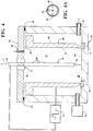
- Figure 4A provides a cross-sectional view of the consumable metallic electrode 28 of Figure 4 .
- the consumable metallic electrode 28 may be formed with or without orifices 50.
- the method next includes providing the sealed deposition chamber 52 sufficient for sputtering the wear resistant layer 22 and metallic adhesive layer 24 onto the inner surface 26 of the cylinder liner 20.
- the cylinder liner 20 provides a portion of the deposition chamber 52 along the inner surface 26 of the body 30. This is done by coving and sealing the first opening 36 and the second opening 38 of the body 30.
- the sealing steps preferably include disposing a first cover 56 along the first body end 32 and disposing a second cover 58 along the second body end 34.
- the first cover 56 is typically a sheet
- the second cover 58 is typically an open half-cylinder presenting an inner cover surface 60.
- the covers 56, 58 are typically formed of steel.
- the method also typically includes disposing a first seal 64 on the first body end 32, disposing the first cover 56 on the first seal 64, disposing a second seal 66 around the outer surface 42 of the body 30 adjacent the second body end 34, disposing the second body end 34 in the open half-cylinder, and engaging the second seal 66 with the inner cover surface 60 of the second cover 58 to seal the deposition chamber 52.
- the step of disposing the second body end 34 in the open half cylinder typically includes spacing the second body end 34 from the second cover 58 such that the second body end 34 and a portion of the outer surface 42 of the body 30 provide the deposition chamber 52.
- the first and second seals 64, 66 can include any type of gasket, such as an O-ring formed of rubber.
- the method next includes securing the first cover 56 and the body 30 in place relative to one another, for example using a clamp and bolts.
- the body 30 and the consumable metallic electrode 28 are disposed in a separate sealed deposition chamber 52 provided by the first cover 56 and the second cover 58.
- an insulating support 62 is disposed on the inner cover surface 60, and the second body end 34 is mounted on the insulating support 62.
- the insulating support 62 can be a ring or a plurality of pucks, typically formed of a ceramic material.
- the first seal 64 is then disposed on an upper end of the second cover 58, and the first cover 56 is disposed on the first seal 64 to provide the sealed deposition chamber 52.
- the first cover 56 and second cover 58 can provided a double-wall water-cooled deposition chamber 52.
- the method next includes providing a gas inlet 68 to provide a carrier gas into the deposition chamber 52, and providing a vacuum pump 70 to reduce the pressure in the deposition chamber 52 prior to sputtering.
- This step can include extending the gas inlet 68 through the first cover 56 and into the deposition chamber 52, and extending the vacuum pump 70 through the second cover 58 into the deposition chamber 52.
- a vacuum gage 72 may also be provided for measuring the pressure in the deposition chamber 52, and it typically extends through the second cover 58 into the deposition chamber 52.
- the gas inlet 68 extends through the first cover 56 and into the hollow opening 40.
- Figure 2A provides a cross-sectional view of the consumable metallic electrode 28 with the hollow opening 40 and orifices 50.
- the carrier gas flows through the orifices 50 and is distributed more evenly throughout deposition chamber 52, compared to the embodiment of Figures 1 and 4 .
- the method also includes providing a power supply 74 for applying a negative voltage to the first electrode end 44 of the consumable metallic electrode 28, as shown in Figures 1-4 , which is necessary to sputter the consumable metallic electrode 28 onto the inner surface 26 of the body 30.
- the power supply 74 and the first electrode end 44 can be interconnected by an electrically isolating feed-through 76 extending through the first cover 56.
- the method includes providing the conditions necessary to sputter the metal of the consumable metallic electrode 28 onto the inner surface 26. This includes decreasing the pressure of the deposition chamber 52 to form a vacuum, and applying a negative voltage to the first electrode end 44 to provide plasma in the deposition chamber 52, typically a glow plasma or hollow cathode discharge plasma.
- the voltage is provided by the power supply 74 and is typically a pulsed radio frequency (RF) voltage or a pulsed direct current (DC) voltage.
- the method also includes supplying a carrier gas including positively charged ions into the sealed deposition chamber 52.
- the carrier gas can be supplied to the deposition chamber 52 for a period of time to clean the inner surface 26 of the body 30, prior to sputtering the metal onto the inner surface 26.
- the positively charged ions typically include at least one of argon (Ar) and hydrogen (H 2 ).
- the step of providing the carrier gas includes providing the carrier gas into the hollow opening 40 and through the orifices 50 of the consumable metallic electrode 28 and into the deposition chamber 52.
- the combination of the low pressure vacuum, negative voltage, and positive ions of the carrier gas causes sputtering of the metal of the consumable metallic electrode 28 onto the inner surface 26 of the body 30.
- the sputtering step provides the metallic adhesive layer 24 formed of the metal of the consumable metallic electrode 28 on the inner surface 26 of the body 30.
- the method can include increasing the pressure of the deposition chamber 52 to adjust the amount of metal sputtered onto the inner surface 26 of the body 30, or adjusting the amount of carrier gas supplied to the deposition chamber 52 to adjust the amount of metal sputtered onto the inner surface 26 of the body 30.
- the thickness t a of the metallic adhesive layer 24 formed on the inner surface 26 of the body 30 is substantially uniform.
- the thickness t a extends perpendicular to the center axis A and varies by not more than 5% along at least 70% of the inner length l i , preferably not more than 3% along at least 70% of the inner length l i , or not more than 1% along at least 70% of the inner length l i .
- the thickness t a may decrease slightly adjacent the first body end 32 and the second body end 34.
- the metallic adhesive layer 24 is disposed on the second body end 34 and on at least a portion of the outer surface 42, between the second body end 34 and the second seal 66.
- the metallic adhesive layer 24 extends along the outer surface 42 from the second body end 34 toward the first body end 32 and along 1 to 40% of the outer length l o .
- the metallic adhesive layer 24 is disposed on at least a portion of the first electrode end 44 between the inner surface 26 and the first seal 64.
- Figure 5 illustrates the location of the metallic adhesive layer 24 of this embodiment.
- the method includes providing at least one wear resistant component through the gas inlet 68 and into the deposition chamber 52, and depositing the wear resistant component on the metallic adhesive layer 24 to form the wear resistant layer 22.
- the at least one wear resistant component includes a hydrocarbon, such as acetylene or methane.
- the wear resistant component can also include silicon, derived from trimethylsilane, or germanium from germanium containing gas precursor.
- the wear resistant layer 22 formed from the resistant component is diamond-like carbon (DLC) coating.
- DLC diamond-like carbon
- the thickness t w of the wear resistant layer 22 formed on the inner surface 26 of the body 30 is also substantially uniform.
- the thickness t w extends perpendicular to the center axis A and varies by not more than 5% along at least 70% of the inner length l i , preferably not more than 3% along at least 70% of the inner length l i , or not more than 1% along at least 70% of the inner length l i .
- the method can also include forming at least one intermediate metallic layer 78 between the metallic adhesive layer 24 and the wear resistant layer 22.
- the intermediate metallic layer 78 is typically formed of a mixture of the metal of the consumable metallic electrode 28 and at least one secondary component, such as nitrogen.
- the method includes providing the at least one secondary component in the carrier gas after sputtering at least some of the metal of the consumable metallic electrode 28 and before depositing the wear resistant component onto the inner surface 26.
- a mixture of the secondary component and the metal of the consumable metallic electrode 28 is sputtered onto the adhesive metallic layer to provide the intermediate metallic layer 78 on the adhesive metallic layer.
- the intermediate metallic layer 78 consists of CrN or TiN.
- the method can also include providing a plurality of the wear resistant layers 22 and a plurality of the intermediate metallic layers 78, wherein adjacent wear resistant layers 22 can be spaced from one another by the intermediate metallic layers 78.
- the wear resistant layers 22 and intermediate metallic layers 78 can each have the same composition, or different compositions.
- the method includes providing a plurality of the metallic adhesive layers 24 and a plurality of the wear resistant layers 22, wherein adjacent wear resistant layers 22 can be spaced from one another by the metallic adhesive layers 24.
- the cylinder liner 20 includes the body 30 formed of the metal material extending circumferentially along the center axis A and longitudinally from the first body end 32 to the second body end 34.
- the body 30 includes the inner surface 26 facing the center axis A and extending longitudinally from the first body end 32 to the second body end 34.
- the inner surface 26 surrounds the center axis A and presents the bore having a cylindrical shape between the first body end 32 and the second body end 34.
- the inner surface 26 also has the inner length l i extending from the first body end 32 to the second body end 34.
- the first body end 32 presents a first opening 36 surrounding the center axis A and having a circular shape
- the second body end 34 presents a second opening 38 surrounding the center axis A and having a circular shape.
- the bore has a volume capable of receiving a piston such that the piston can reciprocate within the cylinder liner 20 and slide along the inner surface 26 during operation of the internal combustion engine.
- the body 30 also presents the outer surface 42 facing opposite the inner surface 26 and extending longitudinally from the first body end 32 to the second body end 34.
- the outer surface 42 has an outer length l o extending from the first body end 32 to the second body end 34.
- the metal material of the body 30 has a hardness of at least 20 HRC and a thermal conductivity of 40 to 50 W/(m ⁇ K) and is capable of withstanding extreme conductions during a typical combustion cycle.
- the metal material of the body 30 is typically steel or a steel alloy.
- the wear resistant layer 22 is disposed on the inner surface 26 and is applied by sputtering, as discussed above.
- the wear resistant layer 22 is a diamond-like carbon (DLC) coating.
- the DLC coating is typically derived from a hydrocarbon gases, such as acetylene, or methane, and at least one of silicon, such as trimethylsilane, or germanium.
- the wear resistant layer 22 typically extends continuously from the first body end 32 to the second body end 34.
- the thickness t w of the wear resistant layer 22 formed on the inner surface 26 of the body 30 is substantially uniform.
- the thickness t w of the wear resistant layer 22 extends perpendicular to the center axis A and varies by not more than 5% along at least 70% of the inner length l i , preferably not more than 3% along at least 70% of the inner length l i , or not more than 1% along at least 70% of the inner length l i .
- the metallic adhesive layer 24 is disposed between the wear resistant layer 22 and the inner surface 26.
- the metallic adhesive layer 24 adheres the wear resistant layer 22 to the inner surface 26.
- the metallic adhesive layer 24 is sandwiched between the wear resistant layer 22 and the inner surface 26, such that the metallic adhesive layer 24 is disposed directly on the inner surface 26 and the wear resistant layer 22 is disposed directly on the metallic adhesive layer 24.
- the metallic adhesive layer 24 comprises metal in an amount of at least 90 wt. %, based on the total weight of the metallic adhesive layer 24, and preferably consists essentially of metal.
- the metal of the metallic adhesive layer 24 includes at least one of chromium and titanium, and preferably consists of chromium or titanium.
- the method used to apply the metallic adhesive layer 24 provides a generally uniform thickness t a between the inner surface 26 and the center axis A and extending perpendicular to the center axis A.
- the thickness t a of the metallic adhesive layer 24 varies by not more than 5% along at least 70% of the inner length l i , preferably by not more than 3% along at least 70% of the inner length l i , or not more than 1% along at least 70% of the inner length l i (l i ).
- the metallic adhesive layer 24 is disposed on at least a portion of the outer surface 42 adjacent the second body end 34.
- the metallic adhesive layer 24 extends along the outer surface 42 from the second body end 34 toward the first body end 32 and along 1 to 40% of the outer length l o .
- the cylinder liner 20 can also include an intermediate metallic layer 78 between the metallic adhesive layer 24 and the wear resistant layer 22.
- the intermediate metallic layer 78 comprises a mixture of the material of the metallic adhesive layer 24 and a second component, such as nitrogen.
- the intermediate metallic layer 78 can be formed of CrN or TiN.
- the cylinder liner 20 includes a plurality of the wear resistant layers 22 and a plurality of the intermediate metallic layers 78, wherein adjacent wear resistant layers 22 are spaced from one another by the intermediate metallic layers 78.
- the wear resistant layers 22 and intermediate metallic layers 78 can each have the same composition, or different compositions.
- the cylinder liner 20 includes a plurality of the metallic adhesive layers 24 and a plurality of the wear resistant layers 22, wherein adjacent wear resistant layers 22 are spaced from one another by the metallic adhesive layers 24.
- the cylinder liner 20 includes two wear resistant layers 22 and one metallic adhesive layer 24 bonding the wear resistant layers 22 to the inner surface 26 of the body 30.
- the outer wear resistant layer 22 is a DLC coating including methane
- the inner wear resistant layer 22 is a DLC coating including silicon
- the metallic adhesive layer 24 is formed of chromium.
- the cylinder liner 20 includes three wear resistant layers 22, two intermediate metallic layers 78, each spacing adjacent wear resistant layers 22, and one metallic adhesive layer 24 bonding the innermost wear resistant layers 22 to the inner surface 26 of the body 30.
- the wear resistant layers 22 are each a DLC coating
- the intermediate metallic layers 78 are each formed of CrN
- the metallic adhesive layer 24 is formed of chromium.
Landscapes
- Chemical & Material Sciences (AREA)
- Engineering & Computer Science (AREA)
- Mechanical Engineering (AREA)
- Chemical Kinetics & Catalysis (AREA)
- Materials Engineering (AREA)
- Metallurgy (AREA)
- Organic Chemistry (AREA)
- Inorganic Chemistry (AREA)
- General Engineering & Computer Science (AREA)
- Combustion & Propulsion (AREA)
- Plasma & Fusion (AREA)
- Analytical Chemistry (AREA)
- Physics & Mathematics (AREA)
- Physical Vapour Deposition (AREA)
- Cylinder Crankcases Of Internal Combustion Engines (AREA)
- Pistons, Piston Rings, And Cylinders (AREA)
- Chemical Vapour Deposition (AREA)
- Coating By Spraying Or Casting (AREA)
- Gasket Seals (AREA)
Abstract
Description
- This invention relates generally to coated cylinder liners and methods of manufacturing the coated cylinder liners.
- Cylinders of internal combustion engines often include a liner or sleeve fitted into the engine block. The cylinder liner includes an outer surface and inner surface surrounding a cylindrical area. The inner surface of the cylinder liner faces toward a piston and provides an interface or sliding surface for the piston rings during a combustion cycle and operation of the internal combustion engine. Thus, the cylinder liner is typically formed of a hard, wear resistant material. A wear resistant coating, such as a diamond-like carbon (DLC) coating, can also be applied on the inner surface to enhance wear resistance.
- One aspect of the invention provides a method of manufacturing a coated cylinder liner. The method includes providing a body including an inner surface extending from a first body end to a second body end. The inner surface surrounds a center axis to present a bore, a first opening at the first body end, and a second opening at the second body end. The method next includes disposing a consumable metallic electrode formed of metal in the bore of the body. The method then includes sealing the first opening and the second opening to form a deposition chamber along the inner surface, and sputtering the metal of the consumable metallic electrode onto the inner surface of the body.
- Another method of manufacturing a coated cylinder liner includes providing a body including an inner surface extending from a first body end to a second body end. The inner surface surrounds a center axis to present a bore, a first opening at the first body end, and a second opening at the second body end. The method next includes disposing a consumable metallic electrode formed of metal in the bore of the body, and providing at least one magnet along the consumable metallic electrode. The method then includes magnetron sputtering the metal of the consumable metallic electrode onto the inner surface of the body.
- Yet another method of manufacturing a coated cylinder includes providing a body including an inner surface extending from a first body end to a second body end. The inner surface surrounds a center axis to present a bore, a first opening at the first body end, and a second opening at the second body end. The method next includes disposing a consumable metallic electrode formed of metal in the bore of the body. The consumable metallic electrode is formed of metal and includes an electrode wall presenting a hollow opening along the center axis and a plurality of orifices extending through the electrode wall. The method next includes providing a carrier gas through the hollow opening and orifices, and sputtering the metal of the consumable metallic electrode onto the inner surface of the body.
- Yet another aspect of the invention provides a coated cylinder liner including a body with an inner surface extending from a first body end to a second body end. The inner surface has an inner length extending from the first body end to the second body end and surrounds a center axis to present a bore, a first opening at the first body end, and a second opening at the second body end. A wear resistant layer including a hydrocarbon is disposed over the inner surface, and a metallic adhesive layer is disposed between the wear resistant layer and the inner surface. The metallic adhesive layer is formed of metal and has a thickness extending between the inner surface and the center axis. The thickness of metallic adhesive layer varies by not more than 5% along at least 70% of the inner length.
- The method of the present invention provides a generally uniform, thick, wear resistant layer and metallic adhesive layer along the inner surface of the cylinder liner in an efficient manner. The metallic adhesive layer provides superior adhesion such that the layers do not flake during use of the cylinder liner in a combustion engine.
- Other advantages of the present invention will be readily appreciated, as the same becomes better understood by reference to the following detailed description when considered in connection with the accompanying drawings wherein:
-
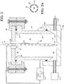
Figure 1 is a cross-sectional view of a cylinder liner and equipment used to coat the cylinder liner according to one embodiment of the invention; -
Figure 2 is a cross-sectional view of a cylinder liner and equipment used to coat the cylinder liner according to another embodiment of the invention; -
Figure 2A provides a cross-sectional top view of a consumable metallic electrode ofFigure 2 ; -
Figure 3 is a cross-sectional view of a cylinder liner and equipment used to coat the cylinder liner according to yet another embodiment of the invention; -
Figure 4 is a cross-sectional view of a cylinder liner and equipment used to coat the cylinder liner according to yet another embodiment of the invention; -
Figure 4A provides a cross-sectional top view of a consumable metallic electrode ofFigure 4 ; -
Figure 5 is a cross-sectional view of a coated cylinder liner according to one embodiment of the invention; -
Figure 5A is an enlarged view of a portion of the coated cylinder liner ofFigure 5 ; -
Figure 5B illustrates a portion of a coated cylinder liner according to another embodiment of the invention; and -
Figure 5C illustrates a portion of a coated cylinder liner according to yet another embodiment of the invention. - One aspect of the invention provides a method of forming a coated
cylinder liner 20 for being disposed in a cylinder block and receiving a piston of an internal combustion engine. Exemplary equipment used to manufacturing the coatedcylinder liner 20 are shown inFigures 1-4 ; and an exemplary embodiment of the coatedcylinder liner 20 formed according to the method of the present invention is shown inFigure 5 . The method includes sputtering a wearresistant layer 22, such as a diamond-liked carbon (DLC) coating, and metallicadhesive layer 24, such as a chromium or titanium coating, on aninner surface 26 of thecylinder liner 20 to provide superior adhesion and prevent during use of thecylinder liner 20 in the combustion engine. The metallicadhesive layer 24 is provided by sputtering a consumablemetallic electrode 28 onto theinner surface 26 of thecylinder liner 20. The thickness ta of the metallicadhesive layer 24 is substantially uniform and varies by not more than 5% along an inner length li of theinner surface 26. - The method of forming the
cylinder liner 20 first includes providing abody 30 extending circumferentially along a center axis A and longitudinally between from afirst body end 32 to asecond body end 34. Thebody 30 includes theinner surface 26 facing the center axis A and extending longitudinally from thefirst body end 32 to thesecond body end 34. Theinner surface 26 presents a bore having a cylindrical shape between thefirst body end 32 and the second body end 34. The bore has volume capable of receiving a piston such that the piston can reciprocate within thecylinder liner 20 and slide along theinner surface 26 during operation of the internal combustion engine. Theinner surface 26 presents the inner length li extending from thefirst body end 32 to thesecond body end 34. Thefirst body end 32 presents afirst opening 36 surrounding the center axis A, thesecond body end 34 presents asecond opening 38 surrounding the center axis A, and bothopenings body 30 also presents anouter surface 42 facing opposite theinner surface 26 and extending longitudinally from thefirst body end 32 to thesecond body end 34. Theouter surface 42 has an outer length lo extending from thefirst body end 32 to thesecond body end 34. The metal material of thebody 30 has a hardness of at least 20 HRC and a thermal conductivity of 40 to 50 W/(m·K) such that it is capable of withstanding extreme conductions during a typical combustion cycle. Thebody 30 typically consists of steel or a steel alloy. - The method next includes disposing the consumable
metallic electrode 28 in the bore of thebody 30 along the center axis A, as shown inFigures 1-3 . The consumablemetallic electrode 28 extends longitudinally along the center axis A from afirst electrode end 44 to asecond electrode end 46. The consumablemetallic electrode 28 has a diameter less than the diameter of theinner surface 26 to present a space therebetween. - The consumable
metallic electrode 28 is formed of metal, and typically consists essentially of metal, or includes metal in an amount of at least 90 wt. %, based on the total weight of the consumablemetallic electrode 28. According to one embodiment, consumablemetallic electrode 28 includes at least one of chromium and titanium, and preferably consists essentially of chromium and/or titanium. - In one embodiment, shown in
Figures 1 , the consumablemetallic electrode 28 is solid from thefirst electrode end 44 to thesecond electrode end 46. In another embodiment, shown inFigures 2-4 , the consumablemetallic electrode 28 includes anelectrode wall 48 surrounding the center axis A and presenting ahollow opening 40 from thefirst electrode end 44 to thesecond electrode end 46. In the embodiments ofFigures 2 and3 , theelectrode wall 48 includes a plurality oforifices 50 extending from thehollow opening 40 to thedeposition chamber 52. In the embodiment ofFigure 4 , the consumablemetallic electrode 28 includes theelectrode wall 48 presenting thehollow opening 40, and amagnet 54 is disposed in thehollow opening 40 along theelectrode wall 48 such that the metallicadhesive layer 24 and the wearresistant layer 22 can be applied by magnetron sputtering.Figure 4A provides a cross-sectional view of the consumablemetallic electrode 28 ofFigure 4 . In this embodiment, the consumablemetallic electrode 28 may be formed with or withoutorifices 50. - The method next includes providing the sealed
deposition chamber 52 sufficient for sputtering the wearresistant layer 22 and metallicadhesive layer 24 onto theinner surface 26 of thecylinder liner 20. In the embodiments ofFigures 1 and2 , thecylinder liner 20 provides a portion of thedeposition chamber 52 along theinner surface 26 of thebody 30. This is done by coving and sealing thefirst opening 36 and thesecond opening 38 of thebody 30. The sealing steps preferably include disposing afirst cover 56 along thefirst body end 32 and disposing a second cover 58 along thesecond body end 34. Thefirst cover 56 is typically a sheet, and the second cover 58 is typically an open half-cylinder presenting aninner cover surface 60. Thecovers 56, 58 are typically formed of steel. - When the
cylinder liner 20 provides thedeposition chamber 52, the method also typically includes disposing afirst seal 64 on thefirst body end 32, disposing thefirst cover 56 on thefirst seal 64, disposing asecond seal 66 around theouter surface 42 of thebody 30 adjacent thesecond body end 34, disposing thesecond body end 34 in the open half-cylinder, and engaging thesecond seal 66 with theinner cover surface 60 of the second cover 58 to seal thedeposition chamber 52. The step of disposing thesecond body end 34 in the open half cylinder typically includes spacing the second body end 34 from the second cover 58 such that thesecond body end 34 and a portion of theouter surface 42 of thebody 30 provide thedeposition chamber 52. The first andsecond seals first cover 56 and thebody 30 in place relative to one another, for example using a clamp and bolts. - In the embodiments of
Figures 3 and4 , thebody 30 and the consumablemetallic electrode 28 are disposed in a separate sealeddeposition chamber 52 provided by thefirst cover 56 and the second cover 58. In this case, an insulatingsupport 62 is disposed on theinner cover surface 60, and thesecond body end 34 is mounted on the insulatingsupport 62. The insulatingsupport 62 can be a ring or a plurality of pucks, typically formed of a ceramic material. Thefirst seal 64 is then disposed on an upper end of the second cover 58, and thefirst cover 56 is disposed on thefirst seal 64 to provide the sealeddeposition chamber 52. In this embodiment, thefirst cover 56 and second cover 58 can provided a double-wall water-cooleddeposition chamber 52. - The method next includes providing a
gas inlet 68 to provide a carrier gas into thedeposition chamber 52, and providing avacuum pump 70 to reduce the pressure in thedeposition chamber 52 prior to sputtering. This step can include extending thegas inlet 68 through thefirst cover 56 and into thedeposition chamber 52, and extending thevacuum pump 70 through the second cover 58 into thedeposition chamber 52. Avacuum gage 72 may also be provided for measuring the pressure in thedeposition chamber 52, and it typically extends through the second cover 58 into thedeposition chamber 52. In the embodiments ofFigures 2 and3 , when the consumablemetallic electrode 28 provides thehollow opening 40 andorifices 50, thegas inlet 68 extends through thefirst cover 56 and into thehollow opening 40.Figure 2A provides a cross-sectional view of the consumablemetallic electrode 28 with thehollow opening 40 andorifices 50. In this embodiment, the carrier gas flows through theorifices 50 and is distributed more evenly throughoutdeposition chamber 52, compared to the embodiment ofFigures 1 and4 . - The method also includes providing a
power supply 74 for applying a negative voltage to thefirst electrode end 44 of the consumablemetallic electrode 28, as shown inFigures 1-4 , which is necessary to sputter the consumablemetallic electrode 28 onto theinner surface 26 of thebody 30. Thepower supply 74 and thefirst electrode end 44 can be interconnected by an electrically isolating feed-through 76 extending through thefirst cover 56. - Once the sealed
deposition chamber 52 and equipment are provided, the method includes providing the conditions necessary to sputter the metal of the consumablemetallic electrode 28 onto theinner surface 26. This includes decreasing the pressure of thedeposition chamber 52 to form a vacuum, and applying a negative voltage to thefirst electrode end 44 to provide plasma in thedeposition chamber 52, typically a glow plasma or hollow cathode discharge plasma. The voltage is provided by thepower supply 74 and is typically a pulsed radio frequency (RF) voltage or a pulsed direct current (DC) voltage. The method also includes supplying a carrier gas including positively charged ions into the sealeddeposition chamber 52. The carrier gas can be supplied to thedeposition chamber 52 for a period of time to clean theinner surface 26 of thebody 30, prior to sputtering the metal onto theinner surface 26. The positively charged ions typically include at least one of argon (Ar) and hydrogen (H2). In the embodiment ofFigures 2 and3 , when the consumablemetallic electrode 28 includes thehollow opening 40 andorifices 50, the step of providing the carrier gas includes providing the carrier gas into thehollow opening 40 and through theorifices 50 of the consumablemetallic electrode 28 and into thedeposition chamber 52. - The combination of the low pressure vacuum, negative voltage, and positive ions of the carrier gas causes sputtering of the metal of the consumable
metallic electrode 28 onto theinner surface 26 of thebody 30. The sputtering step provides the metallicadhesive layer 24 formed of the metal of the consumablemetallic electrode 28 on theinner surface 26 of thebody 30. The method can include increasing the pressure of thedeposition chamber 52 to adjust the amount of metal sputtered onto theinner surface 26 of thebody 30, or adjusting the amount of carrier gas supplied to thedeposition chamber 52 to adjust the amount of metal sputtered onto theinner surface 26 of thebody 30. - As stated above, the thickness ta of the metallic
adhesive layer 24 formed on theinner surface 26 of thebody 30 is substantially uniform. The thickness ta extends perpendicular to the center axis A and varies by not more than 5% along at least 70% of the inner length li, preferably not more than 3% along at least 70% of the inner length li, or not more than 1% along at least 70% of the inner length li. The thickness ta may decrease slightly adjacent thefirst body end 32 and thesecond body end 34. - In the embodiments of
Figures 1 and2 , since thesecond body end 34 is spaced from the second cover 58, the metallicadhesive layer 24 is disposed on thesecond body end 34 and on at least a portion of theouter surface 42, between thesecond body end 34 and thesecond seal 66. In this embodiment, the metallicadhesive layer 24 extends along theouter surface 42 from thesecond body end 34 toward thefirst body end 32 and along 1 to 40% of the outer length lo. Also in the embodiments ofFigures 1 and2 , when thecylinder liner 20 provides thedeposition chamber 52, the metallicadhesive layer 24 is disposed on at least a portion of thefirst electrode end 44 between theinner surface 26 and thefirst seal 64.Figure 5 illustrates the location of the metallicadhesive layer 24 of this embodiment. - After applying the metallic
adhesive layer 24 on theinner surface 26 of thebody 30, the method includes providing at least one wear resistant component through thegas inlet 68 and into thedeposition chamber 52, and depositing the wear resistant component on the metallicadhesive layer 24 to form the wearresistant layer 22. The at least one wear resistant component includes a hydrocarbon, such as acetylene or methane. The wear resistant component can also include silicon, derived from trimethylsilane, or germanium from germanium containing gas precursor. In one preferred embodiment, the wearresistant layer 22 formed from the resistant component is diamond-like carbon (DLC) coating. When thecylinder liner 20 provides thedeposition chamber 52, the wearresistant layer 22 also extends along thesecond body end 34 and along a portion of theouter surface 42. - The thickness tw of the wear
resistant layer 22 formed on theinner surface 26 of thebody 30 is also substantially uniform. The thickness tw extends perpendicular to the center axis A and varies by not more than 5% along at least 70% of the inner length li, preferably not more than 3% along at least 70% of the inner length li, or not more than 1% along at least 70% of the inner length li. - The method can also include forming at least one intermediate
metallic layer 78 between the metallicadhesive layer 24 and the wearresistant layer 22. The intermediatemetallic layer 78 is typically formed of a mixture of the metal of the consumablemetallic electrode 28 and at least one secondary component, such as nitrogen. In this embodiment, the method includes providing the at least one secondary component in the carrier gas after sputtering at least some of the metal of the consumablemetallic electrode 28 and before depositing the wear resistant component onto theinner surface 26. A mixture of the secondary component and the metal of the consumablemetallic electrode 28 is sputtered onto the adhesive metallic layer to provide the intermediatemetallic layer 78 on the adhesive metallic layer. In one embodiment, the intermediatemetallic layer 78 consists of CrN or TiN. - The method can also include providing a plurality of the wear
resistant layers 22 and a plurality of the intermediatemetallic layers 78, wherein adjacent wearresistant layers 22 can be spaced from one another by the intermediate metallic layers 78. The wearresistant layers 22 and intermediatemetallic layers 78 can each have the same composition, or different compositions. In another embodiment, the method includes providing a plurality of the metallicadhesive layers 24 and a plurality of the wearresistant layers 22, wherein adjacent wearresistant layers 22 can be spaced from one another by the metallic adhesive layers 24. - Another aspect of the invention provides the
cylinder liner 20 formed by the method of the present invention. An exemplary embodiment of thecylinder liner 20 is shown inFigure 5 . Thecylinder liner 20 includes thebody 30 formed of the metal material extending circumferentially along the center axis A and longitudinally from thefirst body end 32 to thesecond body end 34. Thebody 30 includes theinner surface 26 facing the center axis A and extending longitudinally from thefirst body end 32 to thesecond body end 34. Theinner surface 26 surrounds the center axis A and presents the bore having a cylindrical shape between thefirst body end 32 and thesecond body end 34. Theinner surface 26 also has the inner length li extending from thefirst body end 32 to thesecond body end 34. Thefirst body end 32 presents afirst opening 36 surrounding the center axis A and having a circular shape, and thesecond body end 34 presents asecond opening 38 surrounding the center axis A and having a circular shape. The bore has a volume capable of receiving a piston such that the piston can reciprocate within thecylinder liner 20 and slide along theinner surface 26 during operation of the internal combustion engine. - The
body 30 also presents theouter surface 42 facing opposite theinner surface 26 and extending longitudinally from thefirst body end 32 to thesecond body end 34. Theouter surface 42 has an outer length lo extending from thefirst body end 32 to thesecond body end 34. The metal material of thebody 30 has a hardness of at least 20 HRC and a thermal conductivity of 40 to 50 W/(m·K) and is capable of withstanding extreme conductions during a typical combustion cycle. The metal material of thebody 30 is typically steel or a steel alloy. - The wear
resistant layer 22 is disposed on theinner surface 26 and is applied by sputtering, as discussed above. In one embodiment, the wearresistant layer 22 is a diamond-like carbon (DLC) coating. The DLC coating is typically derived from a hydrocarbon gases, such as acetylene, or methane, and at least one of silicon, such as trimethylsilane, or germanium. The wearresistant layer 22 typically extends continuously from thefirst body end 32 to thesecond body end 34. The thickness tw of the wearresistant layer 22 formed on theinner surface 26 of thebody 30 is substantially uniform. The thickness tw of the wearresistant layer 22 extends perpendicular to the center axis A and varies by not more than 5% along at least 70% of the inner length li, preferably not more than 3% along at least 70% of the inner length li, or not more than 1% along at least 70% of the inner length li. - The metallic
adhesive layer 24 is disposed between the wearresistant layer 22 and theinner surface 26. The metallicadhesive layer 24 adheres the wearresistant layer 22 to theinner surface 26. In one embodiment, as shown inFigure 5A , the metallicadhesive layer 24 is sandwiched between the wearresistant layer 22 and theinner surface 26, such that the metallicadhesive layer 24 is disposed directly on theinner surface 26 and the wearresistant layer 22 is disposed directly on the metallicadhesive layer 24. The metallicadhesive layer 24 comprises metal in an amount of at least 90 wt. %, based on the total weight of the metallicadhesive layer 24, and preferably consists essentially of metal. In one embodiment, the metal of the metallicadhesive layer 24 includes at least one of chromium and titanium, and preferably consists of chromium or titanium. - The method used to apply the metallic
adhesive layer 24 provides a generally uniform thickness ta between theinner surface 26 and the center axis A and extending perpendicular to the center axis A. The thickness ta of the metallicadhesive layer 24 varies by not more than 5% along at least 70% of the inner length li, preferably by not more than 3% along at least 70% of the inner length li, or not more than 1% along at least 70% of the inner length li (li). - When the
body 30 of thecylinder liner 20 provides thedeposition chamber 52, as shown inFigures 1 and2 , the metallicadhesive layer 24 is disposed on at least a portion of theouter surface 42 adjacent thesecond body end 34. In this case the metallicadhesive layer 24 extends along theouter surface 42 from thesecond body end 34 toward thefirst body end 32 and along 1 to 40% of the outer length lo. - The
cylinder liner 20 can also include an intermediatemetallic layer 78 between the metallicadhesive layer 24 and the wearresistant layer 22. The intermediatemetallic layer 78 comprises a mixture of the material of the metallicadhesive layer 24 and a second component, such as nitrogen. For example, the intermediatemetallic layer 78 can be formed of CrN or TiN. - In certain embodiments, shown in
Figures 5B and 5C , thecylinder liner 20 includes a plurality of the wearresistant layers 22 and a plurality of the intermediatemetallic layers 78, wherein adjacent wearresistant layers 22 are spaced from one another by the intermediate metallic layers 78. The wearresistant layers 22 and intermediatemetallic layers 78 can each have the same composition, or different compositions. In another embodiment, thecylinder liner 20 includes a plurality of the metallicadhesive layers 24 and a plurality of the wearresistant layers 22, wherein adjacent wearresistant layers 22 are spaced from one another by the metallic adhesive layers 24. In the embodiment ofFigure 5B , thecylinder liner 20 includes two wearresistant layers 22 and onemetallic adhesive layer 24 bonding the wearresistant layers 22 to theinner surface 26 of thebody 30. The outer wearresistant layer 22 is a DLC coating including methane, the inner wearresistant layer 22 is a DLC coating including silicon, and the metallicadhesive layer 24 is formed of chromium. In the embodiment ofFigure 5C , thecylinder liner 20 includes three wearresistant layers 22, two intermediatemetallic layers 78, each spacing adjacent wearresistant layers 22, and onemetallic adhesive layer 24 bonding the innermost wearresistant layers 22 to theinner surface 26 of thebody 30. The wearresistant layers 22 are each a DLC coating, the intermediatemetallic layers 78 are each formed of CrN, and the metallicadhesive layer 24 is formed of chromium. - Obviously, many modifications and variations of the present invention are possible in light of the above teachings and may be practiced otherwise than as specifically described while within the scope of the appended claims.
The following numbered paragraphs describe further embodiments of the invention: - 1. A method of manufacturing a coated cylinder liner, comprising the steps of:
- providing a body including an inner surface extending from a first body end to a second body end, the inner surface surrounding a center axis to present a bore and a first opening at the first body end and a second opening at the second body end;
- disposing a consumable metallic electrode in the bore of the body, the consumable metallic electrode being formed of metal;
- sealing the first opening and the second opening to form a deposition chamber along the inner surface; and
- sputtering the metal of the consumable metallic electrode onto the inner surface of the body.
- 2. The method of 1. including depositing a wear resistant component including a hydrocarbon over the inner surface after sputtering at least some of the metal of the consumable metallic electrode onto the inner surface.
- 3. The method of 2. including sputtering a mixture of a secondary component and the metal of the consumable metallic electrode over the inner surface after sputtering at least some of the metal of the consumable metallic electrode onto the inner surface and before depositing the wear resistant component over the inner surface.
- 4. The method of 1. wherein the consumable metallic electrode is solid and the metal of the consumable metallic electrode is selected from the group consisting of chromium and titanium.
- 5. The method of 1. wherein the consumable metallic electrode includes an electrode wall presenting a hollow opening and includes a plurality of orifices extending through the electrode wall; and including the step of providing a carrier gas through the hollow opening and orifices and into the deposition chamber.
- 6. The method of 1. wherein the body includes an outer surface facing opposite the inner surface; and
the step of sealing the first opening and the second opening includes disposing a first seal on the first body end, disposing a first cover on the first seal to seal the first opening, disposing a second seal around a portion of the outer surface of the body adjacent the second body end, and engaging the second seal with a second cover extending along the outer surface of the body and the second opening to seal the second opening. - 7. The method of 6. including providing a vacuum pump through the second cover and into the deposition chamber for reducing the pressure in the deposition chamber;
- applying a negative voltage to the consumable metallic electrode to form a plasma in the deposition chamber; and
- providing a carrier gas including positively charged ions into the deposition chamber.
- 8. The method of 7. wherein the consumable metallic electrode includes an electrode wall presenting a hollow opening along the center axis and includes a plurality of orifices extending through the electrode wall; and wherein the step of providing the carrier gas includes providing the carrier gas through the hollow opening and orifices of the consumable metallic electrode and into the deposition chamber.
- 9. The method of 7. wherein the metal of the consumable metallic electrode is selected from the group consisting of chromium and titanium; and including the steps of
providing a secondary component in the carrier gas after sputtering at least some of the metal of the consumable metallic electrode onto the inner surface, the secondary component being nitrogen; and
providing at least one wear resistant component in the carrier gas after sputtering the secondary component, the wear resistant component including a hydrocarbon. - 10. The method of 6. including spacing the second body end from the second cover such that the second body end and a portion of the outer surface of the body provide the deposition chamber.
- 11. A method of manufacturing a coated cylinder liner, comprising the steps of:
- providing a body including an inner surface extending from a first body end to a second body end, the inner surface surrounding a center axis to present a bore and a first opening at the first body end and a second opening at the second body end;
- disposing a consumable metallic electrode in the bore of the body, the consumable metallic electrode being formed of metal;
- providing at least one magnet along the consumable metallic electrode; and
- magnetron sputtering the metal of the consumable metallic electrode onto the inner surface of the body.
- 12. The method of 11. wherein the consumable metallic electrode includes an electrode wall presenting a hollow opening along the center axis and the at least one magnet is disposed in the hollow opening along the electrode wall.
- 13. A method of manufacturing a coated cylinder liner, comprising the steps of:
- providing a body including an inner surface extending from a first body end to a second body end, the inner surface surrounding a center axis to present a bore and a first opening at the first body end and a second opening at the second body end;
- disposing a consumable metallic electrode in the bore of the body, wherein the consumable metallic electrode is formed of metal and includes an electrode wall presenting a hollow opening along the center axis and includes a plurality of orifices extending through the electrode wall;
- providing a carrier gas through the hollow opening and orifices; and
- sputtering the metal of the consumable metallic electrode onto the inner surface of the body.
- 14. A cylinder liner, comprising:
- a body extending from a first body end to a second body end;
- said body including an inner surface extending from said first body end to said second body and having an inner length extending from said first body end to said second body end;
- said inner surface surrounding a center axis to present a bore and a first opening at said first body end and a second opening at said second body end;
- a wear resistant layer including a hydrocarbon disposed over said inner surface;
- a metallic adhesive layer disposed between said wear resistant layer and said inner surface, said metallic adhesive layer being formed of metal;
- said metallic adhesive layer having a thickness extending between said inner surface and said center axis; and
- said thickness of metallic adhesive layer varying by not more than 5% along at least 70% of said inner length.
- 15. The cylinder liner of 14. wherein said thickness of metallic adhesive layer varies by not more than 3% along at least 70% of said inner length.
- 16. The cylinder liner of 14. wherein said metallic adhesive layer is disposed on said inner surface by sputtering a consumable metallic electrode formed of said metal onto said inner surface, said body includes an outer surface facing opposite said inner surface; and said metallic adhesive layer extends along said second body end and a portion of said outer surface.
- 17. The cylinder liner of 16. wherein said metallic adhesive layer extends along a portion of said first body end.
- 18. The cylinder liner of 14. wherein said metal of said metallic adhesive layer is selected from the group consisting of chromium and titanium, and wherein said wear resistant layer is a diamond-like carbon (DLC) coating.
- 19. A method of forming a cylinder liner for receiving a piston of an internal combustion engine, comprising the steps of:
- providing a body formed of a metal material extending circumferentially along a center axis and longitudinally between from a first body end to a second body end;
- the body including an inner surface facing the center axis and extending longitudinally from the first body end to the second body end;
- the inner surface presenting bore having a cylindrical shape between the first body end and the second body end;
- the inner surface having an inner length extending from the first body end to the second body end;
- the first body end presenting a first opening surrounding the center axis and having a circular shape;
- the second body end presenting a second opening surrounding the center axis and having a circular shape;
- the bore having volume capable of receiving a piston such that the piston can reciprocate within the cylinder liner and slide along the inner surface during operation of the internal combustion engine;
- the body presenting an outer surface facing opposite the inner surface and extending longitudinally from the first body end to the second body end;
- the outer surface having an outer length extending from the first body end to the second body end;
- the metal material of the body having a hardness of and of at least 20 HRC and a thermal conductivity of 40 to 50 W/(m·K);
- the metal material being capable of withstanding extreme conductions during a typical combustion cycle;
- the metal material of the body consisting of steel or a steel alloy;
- disposing a consumable metallic electrode in the bore of the body along the center axis;
- the consumable metallic electrode extending longitudinally along the center axis from a first electrode end to a second electrode end;
- the consumable metallic electrode having a diameter less than the diameter of said inner surface to present a space therebetween;
- the consumable metallic electrode consisting essentially of metal;
- the metal of the consumable metallic electrode including at least one of chromium and titanium;
- sealing the first opening and the second opening of the body to form a deposition chamber along the inner surface of the body;
- the sealing step including disposing a first cover along the first body end and disposing a second cover along the second body end to form the deposition chamber, the covers being formed of steel, the first cover being a sheet, and the second cover being an open half-cylinder presenting an inner cover surface;
- the sealing step including disposing a first seal on the first body end, the first seal being an O-ring formed of rubber and disposing the first cover on the first seal;
- the sealing step including disposing the second body end in the open half-cylinder, disposing a second seal around the outer surface of the body adjacent the second body end, the second seal being an O-ring formed of rubber, and engaging the second seal with the inner cover surface of the second cover to seal the deposition chamber, the second cover extending across the second opening;
- spacing the second body end from the second cover such that the second body end and a portion of the outer surface of the body provide the deposition chamber;
- securing the first cover and the body in place relative to one another;
- providing a gas inlet extending through the first cover and into the deposition chamber for providing a carrier gas into the deposition chamber;
- providing a vacuum pump extending through the second cover to the deposition chamber for reducing the pressure in the deposition chamber;
- providing a vacuum gage extending through the second cover to the deposition chamber for measuring the pressure in the deposition chamber;
- providing a power supply for applying a negative voltage to the first electrode end of the consumable metallic electrode;
- interconnecting the power supply and the first electrode end by an electrically isolating feed-through, the electrically insulating feed-through extending through the first cover;
- applying a negative voltage to the first electrode end to provide plasma in the deposition chamber, the voltage being provided by the power supply and being pulsed, and the voltage being a radio frequency (RF) voltage or a direct current (DC) voltage;
- supplying a carrier gas including positively charged ions into the sealed deposition chamber, the positively charged ions including at least one of argon (Ar) and hydrogen (H2);
- sputtering the metal of the consumable metallic electrode onto the inner surface of the body;
- the sputtering step including forming a metallic adhesive layer consisting of the metal of the consumable metallic electrode on the inner surface of the body, the metallic adhesive layer having a thickness varying by not more than 5% along at least 70% of the inner length;
- increasing the pressure of the deposition chamber to adjust the amount of metal sputtered onto the inner surface of the body;
- adjusting the amount of carrier gas supplied to the deposition chamber to adjust the amount of metal sputtered onto the inner surface of the body;
- the sputtering step including disposing the metallic adhesive layer on at least a portion of the first body between the inner surface and the first seal and disposing the metallic adhesive layer on the second body end and along 1 to 40% of the outer length adjacent the second body end; and
- providing at least one wear resistant component through the gas inlet into the deposition chamber and depositing the wear resistant component onto the metallic adhesive layer to form a wear resistant layer, the at least one wear resistant component including a hydrocarbon and at least one of silicon and germanium, and the wear resistant layer having a thickness varying by not more than 5% along at least 70% of the inner length.
- 20. A cylinder liner for receiving a piston of an internal combustion engine, comprising:
- a body formed of a metal material extending circumferentially along a center axis and longitudinally between from a first body end to a second body end;
- said body including an inner surface facing said center axis and extending longitudinally from said first body end to said second body end;
- said inner surface surrounding said center axis and presenting bore having a cylindrical shape between said first body end and said second body end;
- said inner surface having an inner length extending from said first body end to said second body end;
- said first body end presenting a first opening surrounding said center axis and having a circular shape;
- said second body end presenting a second opening surrounding said center axis and having a circular shape;
- said bore having volume capable of receiving a piston such that said piston can reciprocate within said cylinder liner and slide along said inner surface during operation of the internal combustion engine;
- said body presenting an outer surface facing opposite said inner surface and extending longitudinally from said first body end to said second body end;
- said outer surface having an outer length extending from said first body end to said second body end;
- said metal material of said body having a hardness of at least 20 HRC and a thermal conductivity of 40 to 50 W/(m·K);
- said metal material of said body consisting of steel or a steel alloy;
- a wear resistant layer disposed on said inner surface, said wear resistant layer produced by a sputtering process;
- said wear resistant layer being a diamond-like carbon (DLC) coating;
- said DLC coating including a hydrocarbon and at least one of silicon and germanium;
- said wear resistant layer extending continuously from said first body end to said second body end;
- said wear resistant layer having a thickness extending between said inner surface and said center axis;
- said thickness of said wear resistant layer varying by not more than 5% along at least 70% of said inner length; and
- a metallic adhesive layer disposed between said wear resistant layer and said inner surface;
- said metallic adhesive layer adhering said wear resistant layer to said inner surface;
- said metallic adhesive layer consisting essentially of metal;
- said metal of said metallic adhesive layer including at least one of chromium and titanium;
- said metallic adhesive layer having a thickness extending between said inner surface and said center axis;
- said thickness of said metallic adhesive layer varying by not more than 5% along at least 70% of said inner length; and
- said metallic adhesive layer being disposed on said second body end and along 1 to 40% of said outer length adjacent said second body end.
Claims (7)
- A cylinder liner, comprising:a body extending from a first body end to a second body end;said body including an inner surface extending from said first body end to said second body and having an inner length extending from said first body end to said second body end;said inner surface surrounding a center axis to present a bore and a first opening at said first body end and a second opening at said second body end;a wear resistant layer including a hydrocarbon disposed over said inner surface;a metallic adhesive layer disposed between said wear resistant layer and said inner surface, said metallic adhesive layer being formed of metal;said metallic adhesive layer having a thickness extending between said inner surface and said center axis; andsaid thickness of metallic adhesive layer varying by not more than 5% along at least 70% of said inner length.
- The cylinder liner of claim 1 wherein said thickness of metallic adhesive layer varies by not more than 3% along at least 70% of said inner length.
- The cylinder liner of claim 1, wherein said metallic adhesive layer is disposed on said inner surface by sputtering a consumable metallic electrode formed of said metal onto said inner surface, said body includes an outer surface facing opposite said inner surface; and said metallic adhesive layer extends along said second body end and a portion of said outer surface.
- The cylinder liner of claim 3 wherein said metallic adhesive layer extends along a portion of said first body end.
- The cylinder liner of claim 1 wherein said metal of said metallic adhesive layer is selected from the group consisting of chromium and titanium, and wherein said wear resistant layer is a diamond-like carbon (DLC) coating.
- A method of forming a cylinder liner for receiving a piston of an internal combustion engine, comprising the steps of:providing a body formed of a metal material extending circumferentially along a center axis and longitudinally between from a first body end to a second body end;the body including an inner surface facing the center axis and extending longitudinally from the first body end to the second body end;the inner surface presenting bore having a cylindrical shape between the first body end and the second body end;the inner surface having an inner length extending from the first body end to the second body end;the first body end presenting a first opening surrounding the center axis and having a circular shape;the second body end presenting a second opening surrounding the center axis and having a circular shape;the bore having volume capable of receiving a piston such that the piston can reciprocate within the cylinder liner and slide along the inner surface during operation of the internal combustion engine;the body presenting an outer surface facing opposite the inner surface and extending longitudinally from the first body end to the second body end;the outer surface having an outer length extending from the first body end to the second body end;the metal material of the body having a hardness of and of at least 20 HRC and a thermal conductivity of 40 to 50 W/(m·K);the metal material being capable of withstanding extreme conductions during a typical combustion cycle;the metal material of the body consisting of steel or a steel alloy;disposing a consumable metallic electrode in the bore of the body along the center axis;the consumable metallic electrode extending longitudinally along the center axis from a first electrode end to a second electrode end;the consumable metallic electrode having a diameter less than the diameter of said inner surface to present a space therebetween;the consumable metallic electrode consisting essentially of metal;the metal of the consumable metallic electrode including at least one of chromium and titanium;sealing the first opening and the second opening of the body to form a deposition chamber along the inner surface of the body;the sealing step including disposing a first cover along the first body end and disposing a second cover along the second body end to form the deposition chamber, the covers being formed of steel, the first cover being a sheet, and the second cover being an open half-cylinder presenting an inner cover surface;the sealing step including disposing a first seal on the first body end, the first seal being an O-ring formed of rubber and disposing the first cover on the first seal;the sealing step including disposing the second body end in the open half-cylinder, disposing a second seal around the outer surface of the body adjacent the second body end, the second seal being an O-ring formed of rubber, and engaging the second seal with the inner cover surface of the second cover to seal the deposition chamber, the second cover extending across the second opening;spacing the second body end from the second cover such that the second body end and a portion of the outer surface of the body provide the deposition chamber;securing the first cover and the body in place relative to one another;providing a gas inlet extending through the first cover and into the deposition chamber for providing a carrier gas into the deposition chamber;providing a vacuum pump extending through the second cover to the deposition chamber for reducing the pressure in the deposition chamber;providing a vacuum gage extending through the second cover to the deposition chamber for measuring the pressure in the deposition chamber;providing a power supply for applying a negative voltage to the first electrode end of the consumable metallic electrode;interconnecting the power supply and the first electrode end by an electrically isolating feed-through, the electrically insulating feed-through extending through the first cover;applying a negative voltage to the first electrode end to provide plasma in the deposition chamber, the voltage being provided by the power supply and being pulsed, and the voltage being a radio frequency (RF) voltage or a direct current (DC) voltage;supplying a carrier gas including positively charged ions into the sealed deposition chamber, the positively charged ions including at least one of argon (Ar) and hydrogen (H2);sputtering the metal of the consumable metallic electrode onto the inner surface of the body;the sputtering step including forming a metallic adhesive layer consisting of the metal of the consumable metallic electrode on the inner surface of the body, the metallic adhesive layer having a thickness varying by not more than 5% along at least 70% of the inner length;increasing the pressure of the deposition chamber to adjust the amount of metal sputtered onto the inner surface of the body;adjusting the amount of carrier gas supplied to the deposition chamber to adjust the amount of metal sputtered onto the inner surface of the body;the sputtering step including disposing the metallic adhesive layer on at least a portion of the first body between the inner surface and the first seal and disposing the metallic adhesive layer on the second body end and along 1 to 40% of the outer length adjacent the second body end; andproviding at least one wear resistant component through the gas inlet into the deposition chamber and depositing the wear resistant component onto the metallic adhesive layer to form a wear resistant layer, the at least one wear resistant component including a hydrocarbon and at least one of silicon and germanium, and the wear resistant layer having a thickness varying by not more than 5% along at least 70% of the inner length.
- A cylinder liner for receiving a piston of an internal combustion engine, comprising:a body formed of a metal material extending circumferentially along a center axis and longitudinally between from a first body end to a second body end;said body including an inner surface facing said center axis and extending longitudinally from said first body end to said second body end;said inner surface surrounding said center axis and presenting bore having a cylindrical shape between said first body end and said second body end;said inner surface having an inner length extending from said first body end to said second body end;said first body end presenting a first opening surrounding said center axis and having a circular shape;said second body end presenting a second opening surrounding said center axis and having a circular shape;said bore having volume capable of receiving a piston such that said piston can reciprocate within said cylinder liner and slide along said inner surface during operation of the internal combustion engine;said body presenting an outer surface facing opposite said inner surface and extending longitudinally from said first body end to said second body end;said outer surface having an outer length extending from said first body end to said second body end;said metal material of said body having a hardness of at least 20 HRC and a thermal conductivity of 40 to 50 W/(m·K);said metal material of said body consisting of steel or a steel alloy;a wear resistant layer disposed on said inner surface, said wear resistant layer produced by a sputtering process;said wear resistant layer being a diamond-like carbon (DLC) coating;said DLC coating including a hydrocarbon and at least one of silicon and germanium;said wear resistant layer extending continuously from said first body end to said second body end;said wear resistant layer having a thickness extending between said inner surface and said center axis;said thickness of said wear resistant layer varying by not more than 5% along at least 70% of said inner length; anda metallic adhesive layer disposed between said wear resistant layer and said inner surface;said metallic adhesive layer adhering said wear resistant layer to said inner surface;said metallic adhesive layer consisting essentially of metal;said metal of said metallic adhesive layer including at least one of chromium and titanium;said metallic adhesive layer having a thickness extending between said inner surface and said center axis;said thickness of said metallic adhesive layer varying by not more than 5% along at least 70% of said inner length; andsaid metallic adhesive layer being disposed on said second body end and along 1 to 40% of said outer length adjacent said second body end.
Applications Claiming Priority (3)
| Application Number | Priority Date | Filing Date | Title |
|---|---|---|---|
| US13/801,736 US9765726B2 (en) | 2013-03-13 | 2013-03-13 | Cylinder liners with adhesive metallic layers and methods of forming the cylinder liners |
| PCT/US2014/018818 WO2014163911A2 (en) | 2013-03-13 | 2014-02-27 | Cylinder liners with adhesive metallic layers and methods of forming the cylinder liners |
| EP14709851.1A EP2971220B1 (en) | 2013-03-13 | 2014-02-27 | Method for forming of cylinder liners |
Related Parent Applications (2)
| Application Number | Title | Priority Date | Filing Date |
|---|---|---|---|
| EP14709851.1A Division EP2971220B1 (en) | 2013-03-13 | 2014-02-27 | Method for forming of cylinder liners |
| EP14709851.1A Division-Into EP2971220B1 (en) | 2013-03-13 | 2014-02-27 | Method for forming of cylinder liners |
Publications (2)
| Publication Number | Publication Date |
|---|---|
| EP3495533A2 true EP3495533A2 (en) | 2019-06-12 |
| EP3495533A3 EP3495533A3 (en) | 2019-09-11 |
Family
ID=50272767
Family Applications (2)
| Application Number | Title | Priority Date | Filing Date |
|---|---|---|---|
| EP14709851.1A Active EP2971220B1 (en) | 2013-03-13 | 2014-02-27 | Method for forming of cylinder liners |
| EP19150071.9A Withdrawn EP3495533A3 (en) | 2013-03-13 | 2014-02-27 | Cylinder liners with adhesive metallic layers and methods of forming the cylinder liners |
Family Applications Before (1)
| Application Number | Title | Priority Date | Filing Date |
|---|---|---|---|
| EP14709851.1A Active EP2971220B1 (en) | 2013-03-13 | 2014-02-27 | Method for forming of cylinder liners |
Country Status (7)
| Country | Link |
|---|---|
| US (2) | US9765726B2 (en) |
| EP (2) | EP2971220B1 (en) |
| JP (2) | JP6381623B2 (en) |
| KR (1) | KR20150129754A (en) |
| CN (1) | CN105143496B (en) |
| BR (1) | BR112015022669A2 (en) |
| WO (1) | WO2014163911A2 (en) |
Families Citing this family (16)
| Publication number | Priority date | Publication date | Assignee | Title |
|---|---|---|---|---|
| US9765424B2 (en) * | 2015-02-25 | 2017-09-19 | Engineering And Software System Solutions, Inc. | Method of refurbishing high value articles |
| TWI599431B (en) * | 2015-11-03 | 2017-09-21 | 財團法人工業技術研究院 | Laser treatment device and laser scrap removal device |
| DK179001B1 (en) | 2016-03-09 | 2017-08-07 | Man Diesel & Turbo Filial Af Man Diesel & Turbo Se Tyskland | Engine device of an internal combustion engine |
| CN105925939B (en) * | 2016-04-21 | 2018-05-08 | 鲁东大学 | A kind of preparation process of titanium nitride nano duplex coating air cylinder sleeve of engine |
| US20210147974A1 (en) * | 2017-06-08 | 2021-05-20 | Board Of Trustees Of Michigan State University | Magnetic-field-assisted plasma coating system |
| EP3454029B1 (en) * | 2017-09-12 | 2021-08-25 | TÜV SÜD Schweiz AG | High pressure capsule with coating |
| CN107955938B (en) * | 2018-01-03 | 2024-07-26 | 吉林大学 | Vacuum reaction magnetron sputtering coating device and method for inner cavity of engine cylinder sleeve |
| US12048910B2 (en) | 2018-07-11 | 2024-07-30 | Board Of Trustees Of Michigan State University | Vertically oriented plasma reactor |
| US11371137B2 (en) | 2019-03-15 | 2022-06-28 | Halliburton Energy Services, Inc. | Depositing coatings on and within housings, apparatus, or tools |
| US11371145B2 (en) | 2019-03-15 | 2022-06-28 | Halliburton Energy Services, Inc. | Depositing coatings on and within a housing, apparatus, or tool using a coating system positioned therein |
| US11098672B2 (en) | 2019-08-13 | 2021-08-24 | GM Global Technology Operations LLC | Coated cylinder liner |
| WO2021058547A1 (en) * | 2019-09-23 | 2021-04-01 | Agc Glass Europe | Fabric substrate bearing a carbon based coating and process for making the same |
| US12224165B2 (en) | 2019-12-06 | 2025-02-11 | Board Of Trustees Of Michigan State University | Magnetic-field-assisted plasma coating system |
| US11788187B2 (en) | 2020-08-27 | 2023-10-17 | Halliburton Energy Services, Inc. | Depositing coatings on and within housings, apparatus, or tools utilizing counter current flow of reactants |
| US11788189B2 (en) | 2020-08-27 | 2023-10-17 | Halliburton Energy Services, Inc. | Depositing coatings on and within housings, apparatus, or tools utilizing pressurized cells |
| CN115961238B (en) * | 2022-12-21 | 2025-02-18 | 南京航空航天大学 | Film plating device and film plating method for inner wall of pipe body |
Family Cites Families (43)
| Publication number | Priority date | Publication date | Assignee | Title |
|---|---|---|---|---|
| US3606359A (en) * | 1969-08-08 | 1971-09-20 | Ramsey Corp | Tungsten carbide coated piston rings |
| GB2030180B (en) | 1978-01-26 | 1983-05-25 | Secr Defence | Vapour deposition of metal in plasma discharge |
| DE2820301B2 (en) | 1978-05-10 | 1980-11-06 | Messerschmitt-Boelkow-Blohm Gmbh, 8000 Muenchen | Arrangement for the inner coating of pipes |
| US5301211A (en) | 1992-08-03 | 1994-04-05 | Combustion Engineering, Inc. | Fuel assembly sputtering process |
| JPH06279998A (en) * | 1993-03-29 | 1994-10-04 | Sumitomo Heavy Ind Ltd | Dry coating method for inside surface of cylinder |
| US5693376A (en) * | 1995-06-23 | 1997-12-02 | Wisconsin Alumni Research Foundation | Method for plasma source ion implantation and deposition for cylindrical surfaces |
| US6126793A (en) | 1995-10-17 | 2000-10-03 | Citizen Watch Co., Ltd. | Method of forming films over inner surface of cylindrical member |
| JP2997215B2 (en) * | 1995-10-17 | 2000-01-11 | シチズン時計株式会社 | Method for forming coating on inner peripheral surface of cylindrical member |
| DE19625577A1 (en) * | 1996-06-27 | 1998-01-02 | Vaw Motor Gmbh | Aluminum casting and process for its manufacture |
| DE19637450C1 (en) * | 1996-09-13 | 1998-01-15 | Fraunhofer Ges Forschung | Wear-resistant surface layer structure |
| US5965217A (en) | 1996-10-08 | 1999-10-12 | Citizen Watch Co., Ltd. | Method of forming DLC films over inner surface of cylindrical member |
| US5879763A (en) | 1997-09-03 | 1999-03-09 | Citizen Watch Co., Ltd. | Method of forming hard carbon film over inner surface of cylindrical member |
| US20050163677A1 (en) * | 1998-05-01 | 2005-07-28 | Engelhard Corporation | Catalyst members having electric arc sprayed substrates and methods of making the same |
| EP0969238A1 (en) * | 1998-06-29 | 2000-01-05 | Sinvaco N.V. | Vacuum tight coupling for tube sections |
| JP2003013225A (en) | 2001-06-27 | 2003-01-15 | Matsushita Electric Ind Co Ltd | Hard carbon film manufacturing apparatus and method |
| US7052736B2 (en) | 2002-06-11 | 2006-05-30 | Southwest Research Institute | Method for depositing coatings on the interior surfaces of tubular structures |
| US6764714B2 (en) | 2002-06-11 | 2004-07-20 | Southwest Research Institute | Method for depositing coatings on the interior surfaces of tubular walls |
| US6991219B2 (en) | 2003-01-07 | 2006-01-31 | Ionbond, Llc | Article having a hard lubricious coating |
| US7393589B2 (en) | 2004-01-30 | 2008-07-01 | Ionbond, Inc. | Dual layer diffusion bonded chemical vapor coating for medical implants |
| US7373873B2 (en) | 2004-03-29 | 2008-05-20 | David Maslar | Low friction, high durability ringless piston and piston sleeve |
| US7300684B2 (en) | 2004-07-15 | 2007-11-27 | Sub-One Technology, Inc. | Method and system for coating internal surfaces of prefabricated process piping in the field |
| DE102004041235A1 (en) * | 2004-08-26 | 2006-03-02 | Ina-Schaeffler Kg | Wear resistant coating and method of making same |
| US20060076231A1 (en) * | 2004-10-12 | 2006-04-13 | Southwest Research Institute | Method for magnetron sputter deposition |
| US7541069B2 (en) | 2005-03-07 | 2009-06-02 | Sub-One Technology, Inc. | Method and system for coating internal surfaces using reverse-flow cycling |
| US7608151B2 (en) | 2005-03-07 | 2009-10-27 | Sub-One Technology, Inc. | Method and system for coating sections of internal surfaces |
| US20060278519A1 (en) * | 2005-06-10 | 2006-12-14 | Leszek Malaszewski | Adaptable fixation for cylindrical magnetrons |
| BRPI0506343A (en) | 2005-12-21 | 2006-12-05 | Mahle Metal Leve Sa | chrome nitride coated piston ring |
| US7626135B2 (en) | 2006-05-10 | 2009-12-01 | Sub-One Technology, Inc. | Electrode systems and methods of using electrodes |
| US8273222B2 (en) * | 2006-05-16 | 2012-09-25 | Southwest Research Institute | Apparatus and method for RF plasma enhanced magnetron sputter deposition |
| AT504482B1 (en) | 2007-03-01 | 2008-06-15 | Ruebig Gmbh & Co Kg | Producing optionally-doped coating of amorphous silicon, germanium or their oxides on metallic substrate, subjects area to oxidation before coating deposition |
| DE102007047629A1 (en) | 2007-04-13 | 2008-10-16 | Stein, Ralf | Method of applying a high-strength coating to workpieces and / or materials |
| US7629031B2 (en) | 2007-07-13 | 2009-12-08 | Sub-One Technology, Inc. | Plasma enhanced bonding for improving adhesion and corrosion resistance of deposited films |
| JP4503097B2 (en) | 2008-02-06 | 2010-07-14 | 神奈川県 | DLC-coated sliding member and manufacturing method thereof |
| US8343593B2 (en) | 2008-05-13 | 2013-01-01 | Sub-One Technology, Inc. | Method of coating inner and outer surfaces of pipes for thermal solar and other applications |
| JP5741891B2 (en) | 2009-06-19 | 2015-07-01 | 株式会社ジェイテクト | DLC film forming method |
| AT508962A1 (en) | 2009-11-05 | 2011-05-15 | Miba Gleitlager Gmbh | METHOD FOR PRODUCING A SLIDING BEARING ELEMENT |
| CZ304905B6 (en) * | 2009-11-23 | 2015-01-14 | Shm, S.R.O. | Method of depositing PVD layers, using cylindrical rotating cathode and apparatus for making the same |
| US8715789B2 (en) | 2009-12-18 | 2014-05-06 | Sub-One Technology, Inc. | Chemical vapor deposition for an interior of a hollow article with high aspect ratio |
| DE102010002686A1 (en) | 2010-03-09 | 2011-09-15 | Federal-Mogul Burscheid Gmbh | Sliding element, in particular piston ring, and method for coating a sliding element |
| DE102011003254A1 (en) * | 2011-01-27 | 2012-08-02 | Federal-Mogul Burscheid Gmbh | Sliding element, in particular piston ring, with a coating and method for producing a sliding element |
| US20120312233A1 (en) | 2011-06-10 | 2012-12-13 | Ge Yi | Magnetically Enhanced Thin Film Coating Method and Apparatus |
| WO2012173912A1 (en) | 2011-06-15 | 2012-12-20 | Federal-Mogul Corporation | Germanium containing coating for inner surfaces of cylinder liners |
| DE102014213822A1 (en) * | 2014-07-16 | 2016-01-21 | Federal-Mogul Burscheid Gmbh | Sliding element, in particular piston ring, and method for producing the same |
-
2013
- 2013-03-13 US US13/801,736 patent/US9765726B2/en active Active
-
2014
- 2014-02-27 EP EP14709851.1A patent/EP2971220B1/en active Active
- 2014-02-27 BR BR112015022669A patent/BR112015022669A2/en not_active Application Discontinuation
- 2014-02-27 CN CN201480023253.9A patent/CN105143496B/en not_active Expired - Fee Related
- 2014-02-27 WO PCT/US2014/018818 patent/WO2014163911A2/en not_active Ceased
- 2014-02-27 JP JP2016500445A patent/JP6381623B2/en not_active Expired - Fee Related
- 2014-02-27 EP EP19150071.9A patent/EP3495533A3/en not_active Withdrawn
- 2014-02-27 KR KR1020157026918A patent/KR20150129754A/en not_active Ceased
-
2017
- 2017-09-18 US US15/706,998 patent/US10900439B2/en active Active
-
2018
- 2018-07-31 JP JP2018143523A patent/JP6672394B2/en active Active
Non-Patent Citations (1)
| Title |
|---|
| None |
Also Published As
| Publication number | Publication date |
|---|---|
| US9765726B2 (en) | 2017-09-19 |
| JP2018188737A (en) | 2018-11-29 |
| EP3495533A3 (en) | 2019-09-11 |
| CN105143496A (en) | 2015-12-09 |
| EP2971220A2 (en) | 2016-01-20 |
| WO2014163911A2 (en) | 2014-10-09 |
| EP2971220B1 (en) | 2019-04-03 |
| CN105143496B (en) | 2018-02-02 |
| KR20150129754A (en) | 2015-11-20 |
| US10900439B2 (en) | 2021-01-26 |
| JP6672394B2 (en) | 2020-03-25 |
| JP6381623B2 (en) | 2018-08-29 |
| WO2014163911A3 (en) | 2015-03-05 |
| US20180003125A1 (en) | 2018-01-04 |
| BR112015022669A2 (en) | 2017-07-18 |
| JP2016516134A (en) | 2016-06-02 |
| US20140260955A1 (en) | 2014-09-18 |
Similar Documents
| Publication | Publication Date | Title |
|---|---|---|
| US10900439B2 (en) | Cylinder liners with adhesive metallic layers and methods of forming the cylinder liners | |
| JP2016516134A5 (en) | ||
| RU2520245C2 (en) | Sliding element, particularly, coated piston ring, and method of its fabrication | |
| CN103256306B (en) | The parts of bearings of electrical insulation and bearing | |
| US8201831B2 (en) | Sliding element, in particular piston ring, method for manufacturing a sliding element, sliding system and coating for a sliding element | |
| US7169473B2 (en) | Carbon film-coated article and method of producing the same | |
| US20130136861A1 (en) | Method for coating at least the inner face of a piston ring and piston ring | |
| US20150240944A1 (en) | Sliding element, in particular piston ring, having resistant coating | |
| EP2813599A1 (en) | Device for forming carbon film and method for forming carbon film | |
| CN106521493A (en) | Diamond-like carbon film of gradient structure and preparation method thereof | |
| WO2018220192A1 (en) | Piston ring and method of manufacture | |
| CN106050466A (en) | Piston ring for internal combustion engines | |
| US20050214540A1 (en) | Low friction, high durability ringless piston and piston sleeve | |
| JP2025065561A (en) | Parts coated with a hydrogenated amorphous carbon coating over an undercoat containing chromium, carbon and silicon | |
| US11732343B2 (en) | Part coated with a non-hydrogenated amorphous carbon coating on an undercoat comprising chromium, carbon and silicon | |
| US20170362965A1 (en) | Boron doped ta-c coating for engine components | |
| JP2017214629A (en) | Method and apparatus for depositing ring member | |
| RU2574563C2 (en) | Method for wear-resistant coating deposition on piston seal surface | |
| KR20160034672A (en) | A Material comprising Diamond Like Carbon layer and making process of the same | |
| JPH0510460U (en) | piston ring | |
| PRECHT et al. | Technical University of Koszalin |
Legal Events
| Date | Code | Title | Description |
|---|---|---|---|
| PUAI | Public reference made under article 153(3) epc to a published international application that has entered the european phase |
Free format text: ORIGINAL CODE: 0009012 |
|
| STAA | Information on the status of an ep patent application or granted ep patent |
Free format text: STATUS: THE APPLICATION HAS BEEN PUBLISHED |
|
| AC | Divisional application: reference to earlier application |
Ref document number: 2971220 Country of ref document: EP Kind code of ref document: P |
|
| AK | Designated contracting states |
Kind code of ref document: A2 Designated state(s): AL AT BE BG CH CY CZ DE DK EE ES FI FR GB GR HR HU IE IS IT LI LT LU LV MC MK MT NL NO PL PT RO RS SE SI SK SM TR |
|
| PUAL | Search report despatched |
Free format text: ORIGINAL CODE: 0009013 |
|
| AK | Designated contracting states |
Kind code of ref document: A3 Designated state(s): AL AT BE BG CH CY CZ DE DK EE ES FI FR GB GR HR HU IE IS IT LI LT LU LV MC MK MT NL NO PL PT RO RS SE SI SK SM TR |
|
| RIC1 | Information provided on ipc code assigned before grant |
Ipc: C23C 14/06 20060101ALI20190807BHEP Ipc: C23C 14/02 20060101AFI20190807BHEP Ipc: C23C 14/35 20060101ALI20190807BHEP Ipc: F02F 1/00 20060101ALI20190807BHEP Ipc: H01J 37/34 20060101ALI20190807BHEP Ipc: C23C 28/04 20060101ALI20190807BHEP Ipc: C23C 14/04 20060101ALI20190807BHEP Ipc: C23C 28/00 20060101ALI20190807BHEP Ipc: H01J 37/00 20060101ALI20190807BHEP |
|
| STAA | Information on the status of an ep patent application or granted ep patent |
Free format text: STATUS: REQUEST FOR EXAMINATION WAS MADE |
|
| 17P | Request for examination filed |
Effective date: 20200218 |
|
| RBV | Designated contracting states (corrected) |
Designated state(s): AL AT BE BG CH CY CZ DE DK EE ES FI FR GB GR HR HU IE IS IT LI LT LU LV MC MK MT NL NO PL PT RO RS SE SI SK SM TR |
|
| STAA | Information on the status of an ep patent application or granted ep patent |
Free format text: STATUS: EXAMINATION IS IN PROGRESS |
|
| 17Q | First examination report despatched |
Effective date: 20201126 |
|
| STAA | Information on the status of an ep patent application or granted ep patent |
Free format text: STATUS: THE APPLICATION IS DEEMED TO BE WITHDRAWN |
|
| 18D | Application deemed to be withdrawn |
Effective date: 20210407 |