EP3495246B2 - System und verfahren zur bestimmung eines ersten lenkwinkels eines agv-automatisierten führungsfahrzeugs - Google Patents
System und verfahren zur bestimmung eines ersten lenkwinkels eines agv-automatisierten führungsfahrzeugs Download PDFInfo
- Publication number
- EP3495246B2 EP3495246B2 EP18211089.0A EP18211089A EP3495246B2 EP 3495246 B2 EP3495246 B2 EP 3495246B2 EP 18211089 A EP18211089 A EP 18211089A EP 3495246 B2 EP3495246 B2 EP 3495246B2
- Authority
- EP
- European Patent Office
- Prior art keywords
- agv
- steering angle
- orientation
- determining
- wheel
- Prior art date
- Legal status (The legal status is an assumption and is not a legal conclusion. Google has not performed a legal analysis and makes no representation as to the accuracy of the status listed.)
- Active
Links
Images


Classifications
-
- B—PERFORMING OPERATIONS; TRANSPORTING
- B62—LAND VEHICLES FOR TRAVELLING OTHERWISE THAN ON RAILS
- B62D—MOTOR VEHICLES; TRAILERS
- B62D15/00—Steering not otherwise provided for
- B62D15/02—Steering position indicators ; Steering position determination; Steering aids
- B62D15/021—Determination of steering angle
- B62D15/024—Other means for determination of steering angle without directly measuring it, e.g. deriving from wheel speeds on different sides of the car
-
- B—PERFORMING OPERATIONS; TRANSPORTING
- B62—LAND VEHICLES FOR TRAVELLING OTHERWISE THAN ON RAILS
- B62D—MOTOR VEHICLES; TRAILERS
- B62D1/00—Steering controls, i.e. means for initiating a change of direction of the vehicle
- B62D1/24—Steering controls, i.e. means for initiating a change of direction of the vehicle not vehicle-mounted
- B62D1/28—Steering controls, i.e. means for initiating a change of direction of the vehicle not vehicle-mounted non-mechanical, e.g. following a line or other known markers
- B62D1/283—Steering controls, i.e. means for initiating a change of direction of the vehicle not vehicle-mounted non-mechanical, e.g. following a line or other known markers for unmanned vehicles
-
- B—PERFORMING OPERATIONS; TRANSPORTING
- B66—HOISTING; LIFTING; HAULING
- B66F—HOISTING, LIFTING, HAULING OR PUSHING, NOT OTHERWISE PROVIDED FOR, e.g. DEVICES WHICH APPLY A LIFTING OR PUSHING FORCE DIRECTLY TO THE SURFACE OF A LOAD
- B66F17/00—Safety devices, e.g. for limiting or indicating lifting force
- B66F17/003—Safety devices, e.g. for limiting or indicating lifting force for fork-lift trucks
-
- B—PERFORMING OPERATIONS; TRANSPORTING
- B66—HOISTING; LIFTING; HAULING
- B66F—HOISTING, LIFTING, HAULING OR PUSHING, NOT OTHERWISE PROVIDED FOR, e.g. DEVICES WHICH APPLY A LIFTING OR PUSHING FORCE DIRECTLY TO THE SURFACE OF A LOAD
- B66F9/00—Devices for lifting or lowering bulky or heavy goods for loading or unloading purposes
- B66F9/06—Devices for lifting or lowering bulky or heavy goods for loading or unloading purposes movable, with their loads, on wheels or the like, e.g. fork-lift trucks
- B66F9/063—Automatically guided
-
- B—PERFORMING OPERATIONS; TRANSPORTING
- B66—HOISTING; LIFTING; HAULING
- B66F—HOISTING, LIFTING, HAULING OR PUSHING, NOT OTHERWISE PROVIDED FOR, e.g. DEVICES WHICH APPLY A LIFTING OR PUSHING FORCE DIRECTLY TO THE SURFACE OF A LOAD
- B66F9/00—Devices for lifting or lowering bulky or heavy goods for loading or unloading purposes
- B66F9/06—Devices for lifting or lowering bulky or heavy goods for loading or unloading purposes movable, with their loads, on wheels or the like, e.g. fork-lift trucks
- B66F9/075—Constructional features or details
- B66F9/0755—Position control; Position detectors
-
- B—PERFORMING OPERATIONS; TRANSPORTING
- B66—HOISTING; LIFTING; HAULING
- B66F—HOISTING, LIFTING, HAULING OR PUSHING, NOT OTHERWISE PROVIDED FOR, e.g. DEVICES WHICH APPLY A LIFTING OR PUSHING FORCE DIRECTLY TO THE SURFACE OF A LOAD
- B66F9/00—Devices for lifting or lowering bulky or heavy goods for loading or unloading purposes
- B66F9/06—Devices for lifting or lowering bulky or heavy goods for loading or unloading purposes movable, with their loads, on wheels or the like, e.g. fork-lift trucks
- B66F9/075—Constructional features or details
- B66F9/07568—Steering arrangements
-
- G—PHYSICS
- G05—CONTROLLING; REGULATING
- G05D—SYSTEMS FOR CONTROLLING OR REGULATING NON-ELECTRIC VARIABLES
- G05D1/00—Control of position, course, altitude or attitude of land, water, air or space vehicles, e.g. using automatic pilots
- G05D1/60—Intended control result
- G05D1/617—Safety or protection, e.g. defining protection zones around obstacles or avoiding hazards
- G05D1/622—Obstacle avoidance
-
- G—PHYSICS
- G05—CONTROLLING; REGULATING
- G05D—SYSTEMS FOR CONTROLLING OR REGULATING NON-ELECTRIC VARIABLES
- G05D2105/00—Specific applications of the controlled vehicles
- G05D2105/20—Specific applications of the controlled vehicles for transportation
- G05D2105/28—Specific applications of the controlled vehicles for transportation of freight
-
- G—PHYSICS
- G05—CONTROLLING; REGULATING
- G05D—SYSTEMS FOR CONTROLLING OR REGULATING NON-ELECTRIC VARIABLES
- G05D2107/00—Specific environments of the controlled vehicles
- G05D2107/70—Industrial sites, e.g. warehouses or factories
-
- G—PHYSICS
- G05—CONTROLLING; REGULATING
- G05D—SYSTEMS FOR CONTROLLING OR REGULATING NON-ELECTRIC VARIABLES
- G05D2109/00—Types of controlled vehicles
- G05D2109/10—Land vehicles
-
- G—PHYSICS
- G05—CONTROLLING; REGULATING
- G05D—SYSTEMS FOR CONTROLLING OR REGULATING NON-ELECTRIC VARIABLES
- G05D2111/00—Details of signals used for control of position, course, altitude or attitude of land, water, air or space vehicles
- G05D2111/50—Internal signals, i.e. from sensors located in the vehicle, e.g. from compasses or angular sensors
- G05D2111/54—Internal signals, i.e. from sensors located in the vehicle, e.g. from compasses or angular sensors for measuring the travel distances, e.g. by counting the revolutions of wheels
Definitions
- the present disclosure relates to a system and a method for determining a first steering angle of an AGV-Automated Guided Vehicle. It further relates to a method and a system for improving safety when operating an AGV. The present disclosure even further relates to an AGV, to a computer program product and to a computer-readable medium.
- the steering angle can, for example, be used by safety systems of the AGV when assuring that no person and/or object is situated in the intended driving path of the AGV. In this respect the steering angle is used for determining the intended driving path of the AGV. For such safety systems it is therefore important that a determined steering angle of the AGV is correct.
- a wrong steering angle might otherwise lead to a wrong intended driving path and thus to a wrong zone in front of the AGV where the safety system looks for persons and/or objects.
- a steering angle is to be understood as the angle in relation to a longitudinal axis of a theoretical steering wheel of an AGV. The steering angle is to be understood as to correspond to a heading angle.
- An AGV with a steered wheel monitoring system which senses a steering angle of the steered wheel is disclosed by the document US 5 764 014 .
- a method for determining a first steering angle of an AGV comprises the step of determining a first position and a first orientation of the AGV.
- the method further comprises moving the AGV.
- the method even further comprises determining a second position and a second orientation of the AGV.
- the method yet even further comprises the step of determining a first steering angle of the AGV based on the first position and orientation of the AGV and based on the second position and orientation of the AGV.
- a dedicated steering angle sensor might be dispensed with which might simplify the design of the AGV and save space and cost.
- an additional way of determining a first steering angle can be provided which might increase redundancy at the AGV. This might, for example, lead to increased safety and/or increased operating functionality in case it is determined that the dedicated steering angle sensor is no longer working properly.
- the first position and/or the first orientation is determined via a navigation unit of the AGV.
- a navigation unit of the AGV This provides a specific way of implementation as a navigation unit is already present in several kinds of AGVs. It might further allow the implementation of the method in existing AGVs without the need of further equipment.
- the second position and/or the second orientation is determined via a navigation unit of the AGV.
- the method comprises the step of determining a first steering angle and a first position and orientation of the AGV according to a method of the present disclosure.
- the method further comprises the step of determining a second steering angle of the AGV, wherein the determining of the second steering angle is not based on the first position and orientation of the AGV and the second position and orientation of the AGV.
- the method even further comprises determining whether the first and the second steering angle deviate from each other more than a pre-determined threshold.
- the method further comprises performing safety measures when it is determined that the first and second steering angles deviate more than a pre-determined threshold. This can prevent accidents and save costs related to such an accident.
- the method is based on that the steering angle is corresponding to an angle of a non-powered wheel to a transversal line, when the wheel is not altering angle over a predetermined time period t.
- t is comprised in the range of 1/10 to 2 seconds.
- the time period t starts when a new value for a rotational speed quote is set between the rotating speeds of two individually powered drive wheels.
- the advantage of the above is that the steering angle as a concept can be used for an AGV that has no steerable wheel. This is particularly favourable when a non-powered wheel is a swivel wheel.
- a system for determining a first steering angle of an AGV comprises means for determining a first position and a first orientation of the AGV.
- the system further comprises means for moving the AGV.
- the system even further comprises means for determining a second position and a second orientation of the AGV.
- the system yet even further comprises means for determining the first steering angle of the AGV based on the first position and orientation of the AGV and based on the second position and orientation of the AGV.
- the means for determining a first position and a first orientation of the AGV comprise a navigation unit.
- the means for determining a second position and a second orientation of the AGV comprise a navigation unit.
- the means for determining a first steering angle of the AGV based on the first position and orientation of the AGV and based on the second position and orientation of the AGV comprise a at least one processor being arranged to determine the first steering angle.
- the system comprises a system for determining a first steering angle of an AGV according to the present disclosure.
- the system for improving safety further comprises means for determining a second steering angle of the AGV, wherein the means are arranged to perform the determining of the second steering angle not based on the first position and orientation of the AGV and not based on the second position and orientation of the AGV.
- the system for improving safety even further comprises means for determining whether the first and the second steering angle deviate more than a pre-determined threshold.
- the means for determining a second steering angle of the AGV comprises a steering angle sensor for at least one non-powered wheel, preferably a swivel wheel, of the AGV.
- the means for determining whether the first and the second steering angle deviate more than a pre-determined threshold comprise at least one processor.
- system for improving safety further comprises means for performing safety measures when it is determined that the first and second steering angles deviate more than a pre-determined threshold.
- an AGV which comprises any of the systems according to the present disclosure.
- At least some of the objectives are also achieved by a computer program product comprising instructions which, when the program is executed by a computer, cause the computer to carry out any of the methods according to the present disclosure.
- At least some of the objectives are also achieved by a computer-readable medium comprising instructions which, when executed by a computer, cause the computer to carry out any of the methods according to the present disclosure.
- the system, the AGV, the computer program product and the computer-readable medium have corresponding advantages as have been described in connection with the corresponding examples of the method according to this disclosure.
- AGV is meant an automated guided vehicle. With an AGV is not meant a fork-lift truck that has been upgraded with auto-moving capability.
- the AGV is a completely autonomous vehicle that has been designed for this purpose.
- the AGV has no fixed manual operating panel.
- the AGV has no seat for an operator.
- the AGV can operate in a fleet of AGV's with a leader AGV creating a train of vehicles.
- the AGV has at least two wheels that are individually powered.
- the AGV has no wheel that is steerable around a vertical axis.
- the AGV has in general a very low vehicle body height compared with a fork-lift truck, floor conveyor or the like.
- the height of the AGV is in general comprised between the height of a standard pallet and three standard pallets placed on each other.
- the AGV is meant as an automated vehicle that is used in a warehouse environment for transporting goods.
- An AGV is a vehicle that due to its own mass or the sum of own mass and carried mass could cause damage to fixed installations and/or humans in an undesired contact situation, e.g. crash.
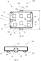
- Fig. 1a and 1b shows, in a schematic way, an AGV 100 according to one embodiment of the present disclosure.
- the AGV comprises an upper surface to be used as a load support member 10. There can be a possibility to raise the upper surface.
- the AGV 100 comprises at least one ground engaging element 30, such as at least three wheels.
- the at least three ground engaging element 30 can comprise an individually powered drive wheel.
- the at least one ground engaging element 30 comprises two, three or four wheels that are individually powered drive wheels.
- the at least one ground engaging element 30 comprises at least one non-powered wheel.
- the non-powered wheel is a swivel wheel.
- the at least one ground engaging element 30 comprises two, three, or four non-powered wheels.
- the AGV 100 comprises a main AGV body 40.
- the main AGV body can comprise a first drive unit 50 arranged to propel the AGV, by propelling a first individually powered drive wheel 31.
- the main AGV body can further comprise a second drive unit 50a that can propel a second drive wheel 31a.
- the main AGV body 40 can comprise a system 299 for determining a first steering angle of the AGV 100.
- the system 299 will be described in more detail in relation to Fig. 2 . However, it should be understood that parts of the system 299 or even the whole system 299 equally well can be arranged at other parts of the AGV 100.
- An AGV 100 is an autonomous vehicle that has no operator travelling with it.
- the AGV 100 needs to be very precise when assessing what objects is in the surroundings.
- the method for determining a first steering angle and the systems of the present disclosure becomes very useful as there is no human interaction at all instants when the AGV 100 is moving around.
- the present disclosure allows for directing a on object sensor, for example a camera unit 45, in a sufficiently narrow corridor for not making it difficult for the AGV 100 to move around. This means that an object sensor on the AGV 100 will focus its detected area on the next upcoming position for the AGV 100 and at the same time ignore less important areas. Less important areas could be straight ahead and straight ahead to the left if the AGV 100 is preparing a right turn forward. In this situation it is more important to detect objects that will occur in the area that is to the right in the path of the AGV 100.
- the system for operating the AGV and method for determining a first steering angle of the present disclosure are useful as an alerted operator which can interact with the AGV in case the AGV behaves unexpectedly is no longer present. This is made by controlling the AGV remotely by a remote control panel, that is for example located on a remote control device or in a control facility for a ware house.
- link refers herein to a communication link which may be a physical connection such as an opto-electronic communication line, or a non-physical connection such as a wireless connection, e.g. a radio link or microwave link.
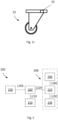
- Fig. 2 shows, in a schematic way, a system 299 for determining a first steering angle of the AGV according to an embodiment of the present disclosure.
- Fig. 2 further shows, in a schematic way, a system 200 for improving safety when operating an AGV according to an embodiment of the present disclosure.
- the system 299 comprises means 240 for determining a first position and a first orientation of the AGV.
- the means 240 can comprise a navigation unit of the AGV.
- the navigation unit can be arranged to determine the first position and the first orientation of the AGV.
- First orientation is meaning in which direction the AGV 100 would head if the AGV would proceed on a straight line from this first position. I.e. it is the orientation in which the AGV 100 is pointing at. In general this means for Fig. 3a that the first orientation 34 is straight up.
- the first orientation 34b would diagonally left upwards, etc. the concept of first must be understood to depend on when a determination of orientation is set.
- the system 299 further comprises means for determining a second position and a second orientation of the AGV 100.
- These means can be the same as the means 240 for determining the first position and the first orientation of the AGV 100. They can be arranged to operate in the same way as described earlier in relation to the means 240.
- the system 299 can comprise at least one sensor 230 at a wheel of the AGV 100, such as at the first individually powered drive wheel.
- the sensor 230 can be arranged to determine the revolutions of the wheel.
- the sensor 230 can be arranged to determine the distance which the wheel is travelling.
- the sensor 230 is preferably a rotary encoder, but other means for measuring is of course possible such as by optic measurement to the surface on which the AGV 100 is operating or an accelerometer etc.
- the system 200 comprises a second control unit 260.
- the second control unit 260 can comprise at least one processor.
- the second control unit 260 can comprise a programmable logic controller, PLC.
- the second control unit 260 can be arranged to control safety measures of the AGV 100.
- the second control unit 260 can be arranged to control operation of the means 210.
- the second control unit 260 can be arranged for communication with the means 210 via a link L210.
- the second control unit 260 can be arranged to receive information from the means 210.
- the second control unit 260 can be arranged to receive the second steering angle of the AGV 100 from the means 210.
- the second control unit 260 can be arranged for communication with the first control unit 220 via a link L220.
- the second control unit 260 can be arranged to receive information from the second control unit 220.
- the second control unit 260 can be arranged to receive the first steering angle of the AGV 100 from the first control unit 220.
- the shifting of the orientation area might be 15 degrees in this case.
- the opening angle is chosen large enough to detect objects and/or persons outside the potential driving path which might be on the way to move into the potential driving path.
- the PPS 250 can be arranged to perform measures when it is detected that a person and/or object is in the potential driving path of the AGV 100 and/or in the scanning area, and/or parts of the scanning area. The measures can depend on the position in the scanning area and/or the distance of the scanned persons and/or objects. Examples of measures are causing warning signals, changing of the driving direction of the AGV 100 and/or changing of the speed of the AGV 100, potentially to a stop of the AGV 100.
- the PPS 250 and in particular the LSU can also be used for navigation purposes in some applications in the same way as described above in relation to the LGU.
- the first and/or second control unit 220, 260 can be arranged for communication with the PPS 250 via a link L250.
- the PPS 250 can be arranged to receive information from the first and/or second control unit 220, 260.
- the PPS 250 can be arranged to receive the first and/or second steering angle of the AGV 100.
- the system 200 comprises means for determining whether the first and the second steering angle deviates more than a pre-determined threshold.
- the means comprise the PPS 250.
- the means comprise the first and/or second control unit 220, 260.
- the pre-determined threshold is a few degrees. It is generally not necessary to have a very low threshold of, for example, 1 degree or less since such deviation naturally may occur due to measurement uncertainties or the like. Further the opening angle of the scanning area and/or the steps in which the orientation of the scanning area can be shifted does usually not necessitate to know the steering angle very exactly since the opening angle has some safety margins and since the shifting of the orientation might not be possible at steps of only one degree, or the like.
- the system 200 can comprise means for performing safety measures when it is determined that the first and second steering angles deviate more than a pre-determined threshold.
- the means can comprise the PPS 250.
- the means can comprise the first and/or second control unit 220, 260.
- the safety measures can be the same safety measures as described above.
- the steering angle can be an angle that is calculated based on the rotational speed v1 of the first individually powered drive wheel and the rotational speed v2 of the second individually powered drive wheel.
- the discussed steering angle is a steering angle of a non-powered wheel. I.e. the difference in rotational speed of the two individually powered drive wheels result in a curved path that occurs with a non-powered wheel, e.g. a swivel wheel.
- a swivel wheel can when changing directions have a start of a steering angle that is not corresponding to a determined steering angle based on v1 and v2. I.e. the swivel wheel can be due to previous motion of the vehicle be positioned in a different direction than what an ensuing direction of the AGV 100 will result in.
- start angle of the swivel wheel does not correspond to the ensuing the steering angle of the motion.
- any reading of an exemplified sensor on the swivel wheel would result in a faulty determination of the steering angle.
- the steering angle based on v1 and v2 should be overriding any start steering angle of any sensor provided to the non-powered wheel.
- the rotational speeds are as an example determined by a rotational sensor 35, 35a, see fig 1a , b.
- the rotational sensor or sensors 35, 35a thus determines the achieved value of rotation of a individually powered drive wheel. This can of course differ from a set value of the rotational speed.
- the steering angle can be instead explained by the heading angle ⁇ , see Fig. 6 and 7 .
- the heading angle ⁇ and the steering angle are of course related to each other, as the steering angle is merely explained in an alternative way by referring to a heading angle as explained below.
- Figure 6 refers to a heading angle ⁇ .
- the first position I is also representing an orientation of the AGV 100 parallel with the y-axis.
- the angle ⁇ is representing the orientation of the vehicle 100 based on the difference between the speed VA, VB of the different individually powered drive wheels 30 31.
- the heading angle ⁇ is determined as the difference in orientation between the first position I and the second position II.
- a turning point TP is defined.
- an angle ⁇ around the turn point TP is travelled by the AGV 100.
- the angle ⁇ is proportional to the heading angle ⁇ .
- the calculation of the angle ⁇ is made based on the different speeds of the wheels 31 and 31a.
- speed VA and VB are here meant the movement per time unit of the position of the wheel in respect of the surface it is supported on. Thus it is not the rotational speed of the wheel as discussed above.
- the heading angle ⁇ is having the same value for a movement along a path 41 where VA and VB do not alter value, for same values of ⁇ .
- the relationship between the steering angle and the heading angle will be an equality, as can be seen in Fig. 7 . From Fig. 7 it is understood that how a theoretical steering wheel 32, in the form of a dotted swivel wheel 32 would be angled for a movement form position I to position II. In position I the wheel 32 has a steering angle of ⁇ ', this angle ⁇ ' is equal of the heading angle ⁇ I.
- the line 42 setting the angle ⁇ ' with regard to the theoretical steering wheel 32 is a transversal perpendicular to the longitudinal axis 13 of the AGV 100.
- steering angle and the heading angle is to be construed as giving the same result in terms of path 41 and are merely used for explanation of the same concept.
- steering angle is interchangeable with heading angle.
- Fig. 3a-d show, in a schematic way, the possible orientation of wheels of an embodiment of an AGV.
- Fig. 3a-d are views directly from the top. It should be emphasised that the figures are only schematic for illustrating the working principle of the present disclosure. Thus, as an example, the size of different elements and the distance between elements might not be at the same scale.
- the depicted AGV has three wheels.
- the depicted AGV comprises one link wheel 30 and two individually powered drive wheels 31, 31a which are individually controllable by means of a first and second drive unit 50, 50a.
- this is only an example and the present disclosure is applicable to AGVs with any numbers of non-powered and individually powered drive wheels.
- a scanning area 80 (partly delimited by the two dashed lines in each of the figures) with an opening angle (defined by the two dashed lines in each of the figures) is depicted as well.
- This scanning area 80 and the opening angle have been described in more detail in relation to Fig. 2 . They are only depicted in a schematic way and may differ in a specific implementation, for example by size, position, and/or opening angle.
- the link wheel is disclosed as when stabilized in the movement of the AGV, and thus the situation of start of movement of the AGV has already occurred, and the link wheel has a stable steering angle fully corresponding to differences in speed of the two individually powered drive wheels.
- the concept of stable steering angle for a non-powered wheel can be determined as an angle of the non-powered wheel in relation to a longitudinal axis 13 of the AGV 100, Fig. 1a .
- the longitudinal axis 13 of the AGV 100 is in general perpendicular to the axis 12 of the individually powered drive wheels of the AGV 100.
- the angle is determined as stated when the swivel wheel is in a stable configuration.
- the stable configuration is preferably set as the angle to the longitudinal axis achieved after a predetermined time t.
- the predetermined time t is in general set to a short time period based on how long the stabilisation phase takes for the swivel wheel.
- t can for example be comprised in the time range of 1/10 to 2s seconds. More preferred to 1/10 to 1 seconds.
- the time period t starts when a new value to the quote v1/v2 is set by the AGV 100.
- a steering angle ⁇ determines in which direction the AGV is moving.
- a centre of rotation 90 determines around which point the AGV is rotating.
- the figures 3a-d have a common coordinate system.
- the steering angle ⁇ is zero and the AGV is moving solely in the y-direction.
- the scanning area is oriented in the driving direction.
- Fig. 3b depicts the same situation as in Fig. 3a , except that the AGV is now oriented in a different direction.
- Fig. 3c depicts the AGV oriented as in Fig. 3a .
- the steering angle ⁇ is not zero.
- the AGV will not move solely in the y-direction but will instead move in a curve away from the y-direction.
- the scanning area has been shifted in its orientation compared to Fig. 3a .
- the scanning area has not to be shifted exactly by the same angle ⁇ as the steering angle.
- Fig. 3d depicts the same situation as in Fig. 3c , except that the AGV is oriented differently in the coordinate system.
- the AGV will eventually arrive at the orientation depicted in Fig. 3d in case the steering angle is kept constant.
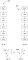
- Fig. 4a-b show, in a schematic way, flowcharts of examples of methods according to the present invention.
- the methods can be applied to any kind of AGVs, especially those described in connection to Fig. 1a-3 .
- the methods are especially suitable for AGVs.
- the described methods can comprise any of the actions which the elements described in relation to Fig. 1a-3 are arranged or configured to. Conversely, the elements described in relation to Fig. 1a-3 can be arranged or configured to perform the method steps described in relation to Fig. 4a-b .
- Fig. 4a depicts a flowchart of a method 400 for determining a first steering angle of an AGV. The method starts with step 410.
- a first position and a first orientation of the AGV is determined. This can be performed by a navigation unit.
- Step 410 can comprise emitting laser pulses.
- Step 410 can comprise detecting reflected laser pulses.
- Step 410 can comprise analysing detected laser pulses, for example regarding time of flight, modulation, or the like.
- the determining of a first position and/or a first orientation can comprise using an inertial measurement unit, IMU, using a global navigation satellite system, GNSS, and/or using a camera system to analyse the surrounding of the AGV.
- Step 410 can comprise comparing information regarding the detected laser pulses and/or regarding images of the camera system with pre-stored information regarding the surrounding of the AGV.
- This pre-stored information can, for example, comprise position, orientation, reflection properties, or the like, of objects in the surrounding of the AGV. Examples of such objects are reflective elements, barcodes, placement of storing arrangements, or the like.
- step 410 can comprise sending and/or receiving information to a system comprising the pre-stored information.
- the system comprising the pre-stored information can be aboard the AGV, outside the AGV, or partly aboard and partly outside the AGV.
- the method continues with step 420.
- step 420 the AGV is moved.
- This can be achieved by any means to move the AGV, such as a combustion engine, an electric motor, or the like.
- This step is performed to assure that not both the second orientation and the second position, which will be described soon, do coincide with the first orientation and the first position.
- the method 400 can comprise the step of waiting a first pre-determined time period between step 410 and step 430. That first pre-determined time period can, for example, be 1, 2, 3, 4, or 5 seconds. In one example, it is determined whether the AGV has been moved during that first pre-determined time period.
- the method 400 is in one example aborted and/or restarted in case the AGV is not moved during the first pre-determined time period.
- the waiting time period is prolonged in case the first pre-determined time period has been passed without moving the AGV.
- the prolongation of time period can equal the first pre-determined time period or be any other suitable time period. It can then be determined whether the AGV has moved during the prolonged time period. If the AGV has been moved, the method can continue with step 430, otherwise the method can be prolonged repeatedly until a movement is detected.
- step 420 comprises determining the distance which the AGV moves. It should be emphasised that the distance which the AGV moves is not necessarily the mere distance between the first and the second position. These two distances usually only coincide in case the AGV moves in a straight line from the first to the second position. However, in case the AGV moves on a curved line, the two distances usually do not coincide.
- step 430 the method continues with step 430.
- Step 430 comprises determining a second position and a second orientation of the AGV. This can be performed in the same manner as described in relation to step 410. Due to the movement of the AGV, at least one of the second position and the second orientation will deviate from the first position and the first orientation of the AGV. In a preferred example, the second position and the second orientation of the AGV are determined in the same way as the first position and the first orientation. This has the advantage that resources are reused and might thus, for example, lower cost and/or weight of the AGV. However, this is not a requirement. In principle, the second position and the second orientation can be determined differently than the first position and orientation. After step 430 the method continues with step 440.
Landscapes
- Engineering & Computer Science (AREA)
- Transportation (AREA)
- Structural Engineering (AREA)
- Mechanical Engineering (AREA)
- Life Sciences & Earth Sciences (AREA)
- Geology (AREA)
- Civil Engineering (AREA)
- Combustion & Propulsion (AREA)
- Chemical & Material Sciences (AREA)
- Aviation & Aerospace Engineering (AREA)
- Radar, Positioning & Navigation (AREA)
- Remote Sensing (AREA)
- Physics & Mathematics (AREA)
- General Physics & Mathematics (AREA)
- Automation & Control Theory (AREA)
- Forklifts And Lifting Vehicles (AREA)
- Control Of Position, Course, Altitude, Or Attitude Of Moving Bodies (AREA)
Claims (14)
- Verfahren (400) zum Bestimmen eines ersten Lenkwinkels (a, a';al; γ) eines AGV's (100), wobei das Verfahren die folgenden Schritte umfasst:- Bestimmen (410) einer ersten Position (I) und einer ersten Ausrichtung des AGV's (100);- Bewegen (420) des AGV's (100);- Bestimmen (430) einer zweiten Position (II) und einer zweiten Ausrichtung des AGV's (100); und- Bestimmen (440) eines ersten Lenkwinkels (a, al; a'; γ) des AGV's (100) basierend auf der ersten Position und Ausrichtung des AGV's (100) und basierend auf der zweiten Position (II) und Ausrichtung des AGV's (100).
- Verfahren (400) nach dem vorhergehenden Anspruch, wobei die erste Position (I) und/oder die erste Ausrichtung über eine Navigationseinheit des AGV's (100) bestimmt wird, vorzugsweise die zweite Position (II) und/oder die zweite Ausrichtung auch über eine Navigationseinheit des AGV's (100) bestimmt wird.
- Verfahren (450) zur Verbesserung der Sicherheit beim Betrieb eines AGV's (100), wobei das Verfahren die folgenden Schritte umfasst:- Bestimmen (400) eines ersten Lenkwinkels (a, al; a'; γ) nach einem der vorhergehenden Ansprüche;- Bestimmen (460) eines zweiten Lenkwinkels (all; a"; γ) des AGV's (100), wobei das Bestimmen des zweiten Lenkwinkels (all; a"; γ) nicht auf der ersten Position (I) und Ausrichtung des AGV's und der zweiten Position (II) und Ausrichtung des AGV's (100) basiert;- Bestimmen (470), ob der erste (a, al; a'; γ) und der zweite Lenkwinkel (all; a"; γ) um mehr als einen vorbestimmten Schwellenwert abweichen.
- Verfahren '(450) nach Anspruch 3, ferner umfassend die folgenden Schritte:- Durchführen (480) von Sicherheitsmaßnahmen, wenn bestimmt wird, dass der erste (a, al; a'; γ) und der zweite Lenkwinkel (all; a'; γ) um mehr als einen vorbestimmten Schwellenwert abweichen.
- Verfahren (400) nach einem der vorhergehenden Ansprüche, wobei der Lenkwinkel einem Winkel eines nicht angetriebenen Rads (32) bezüglich einer Transversallinie (42) entspricht, wenn das Rad (32) seinen Winkel über einen vorgegebenen Zeitraum t nicht ändert, vorzugsweise t im Bereich von 1/10 bis 2 Sekunden liegt, vorzugsweise der Zeitraum t beginnt, wenn ein neuer Wert für die Drehzahl zwischen den Drehzahlen (v1, v2) von zwei einzeln angetriebenen Antriebsrädern (31, 31a) angegeben wird.
- System (299) zum Bestimmen eines ersten Lenkwinkels (a, al; a'; γ) eines AGV's (100), wobei das System Folgendes umfasst:- Mittel (240) zum Bestimmen einer ersten Position (I) und einer ersten Ausrichtung des AGV's (100);- Mittel zum Bewegen des AGV's (100);- Mittel (240) zum Bestimmen einer zweiten Position und einer zweiten Ausrichtung des AGV's (100); und- Mittel (220) zum Bestimmen eines ersten Lenkwinkels (a, al; a'; γ) des AGV's (100) basierend auf der ersten Position (I) und Ausrichtung des AGV's (100) und basierend auf der zweiten Position (II) und Ausrichtung des AGV's (100).
- System (299) nach Anspruch 6, wobei die Mittel (220) zum Bestimmen einer ersten Position (I) und einer ersten Ausrichtung des AGV's (100) eine Navigationseinheit umfassen, vorzugsweise die Mittel (220) zum Bestimmen einer zweiten Position (II) und einer zweiten Ausrichtung des AGV's eine Navigationseinheit umfassen.
- System (299) nach einem der Ansprüche 6-7, wobei die Mittel (240) zum Bestimmen eines ersten Lenkwinkels des AGV's (100) basierend auf der ersten Position und Ausrichtung des AGV's (100) und basierend auf der zweiten Position und Ausrichtung des AGV's (100) mindestens einen Prozessor umfassen, der zum Bestimmen des ersten Lenkwinkels (a, αI; α'; γ) vorgesehen ist.
- System (200) zur Verbesserung der Sicherheit beim Betrieb eines AGV's (100), wobei das System Folgendes umfasst:- ein System (299) zum Bestimmen eines ersten Lenkwinkels (α, αI; α'; γ) eines AGV's (100) nach einem der Ansprüche 7-10;- Mittel (210) zum Bestimmen eines zweiten Lenkwinkels (αII; α"; γ) des AGV's (100), wobei das Bestimmen des zweiten Lenkwinkels (αII; α"; γ) nicht auf der ersten Position (I) und Ausrichtung des AGV's (100) und der zweiten Position (II) und Ausrichtung des AGV's (100) basiert;- Mittel (260) zum Bestimmen, ob der erste und der zweite Lenkwinkel ((αII; α"; γ) um mehr als einen vorbestimmten Schwellenwert abweichen.
- System (200) nach Anspruch 9, wobei die Mittel (210) zum Bestimmen eines zweiten Lenkwinkels des AGV's (100) einen Rotationssensor für zumindest ein Rad (31) des AGV's (100) umfassen, oder wobei die Mittel (210) zum Bestimmen eines zweiten Lenkwinkels des AGV's einen Lenkwinkelsensor (33) für zumindest ein nicht angetriebenes Rad (32), vorzugsweise ein Schwenkrad, des AGV's (100) umfassen.
- System (200) nach einem der Ansprüche 9-10, wobei die Mittel (260) zum Bestimmen, ob der erste (α, αI; α'; γ) und der zweite Lenkwinkel (αII; α"; γ) um mehr als einen vorbestimmten Schwellenwert abweichen, mindestens einen Prozessor umfassen.
- System (200) nach einem der Ansprüche 9-11, ferner umfassend Mittel (250) zum Durchführen von Sicherheitsmaßnahmen, wenn bestimmt wird, dass der erste (α, αI; α'; γ) und der zweite Lenkwinkel (all; a"; γ) um mehr als einen vorbestimmten Schwellenwert abweichen.
- AGV (100), umfassend das System nach einem der Ansprüche 6-12.
- Computerprogrammprodukt umfassend Anweisungen, die, wenn das Programm von einem Computer ausgeführt wird, den Computer veranlassen, ein Verfahren nach einem der Ansprüche 1-5 durchzuführen, vorzugsweise wobei das Computerprogrammprodukt ein computerlesbares Medium umfassend das Programm umfasst.
Applications Claiming Priority (1)
| Application Number | Priority Date | Filing Date | Title |
|---|---|---|---|
| SE1751511A SE542067C2 (en) | 2017-12-08 | 2017-12-08 | System and method for determining a first steering angle of a forklift truck |
Publications (3)
| Publication Number | Publication Date |
|---|---|
| EP3495246A1 EP3495246A1 (de) | 2019-06-12 |
| EP3495246B1 EP3495246B1 (de) | 2020-07-15 |
| EP3495246B2 true EP3495246B2 (de) | 2025-02-26 |
Family
ID=64661192
Family Applications (2)
| Application Number | Title | Priority Date | Filing Date |
|---|---|---|---|
| EP18211068.4A Active EP3495314B1 (de) | 2017-12-08 | 2018-12-07 | System und verfahren zur bestimmung eines ersten lenkwinkels eines gabelstaplers |
| EP18211089.0A Active EP3495246B2 (de) | 2017-12-08 | 2018-12-07 | System und verfahren zur bestimmung eines ersten lenkwinkels eines agv-automatisierten führungsfahrzeugs |
Family Applications Before (1)
| Application Number | Title | Priority Date | Filing Date |
|---|---|---|---|
| EP18211068.4A Active EP3495314B1 (de) | 2017-12-08 | 2018-12-07 | System und verfahren zur bestimmung eines ersten lenkwinkels eines gabelstaplers |
Country Status (2)
| Country | Link |
|---|---|
| EP (2) | EP3495314B1 (de) |
| SE (1) | SE542067C2 (de) |
Families Citing this family (5)
| Publication number | Priority date | Publication date | Assignee | Title |
|---|---|---|---|---|
| EP3521234B1 (de) * | 2018-01-31 | 2020-10-14 | Toyota Material Handling Manufacturing Sweden AB | Materialhandhabungsfahrzeug und system, das solch ein fahrzeug umfasst |
| JP2022059321A (ja) * | 2020-10-01 | 2022-04-13 | 株式会社デンソー | 無人搬送台車 |
| CN112611344B (zh) * | 2020-11-30 | 2023-03-10 | 北京建筑大学 | 一种自主移动式平面度检测方法、设备及存储介质 |
| EP4495051A1 (de) * | 2023-07-19 | 2025-01-22 | Jungheinrich Aktiengesellschaft | Verfahren zur behandlung von hindernissen in einem flurförderzeug während eines fahrbetriebs davon und flurförderzeug |
| WO2025162591A1 (en) * | 2024-02-02 | 2025-08-07 | Abb Schweiz Ag | Autonomous mobile robot |
Family Cites Families (26)
| Publication number | Priority date | Publication date | Assignee | Title |
|---|---|---|---|---|
| JPH0822323A (ja) * | 1994-07-08 | 1996-01-23 | Honda Motor Co Ltd | 移動体の走行制御装置 |
| US5764014A (en) | 1996-02-01 | 1998-06-09 | Mannesmann Dematic Rapistan Corp. | Automated guided vehicle having ground track sensor |
| DE10003564A1 (de) | 2000-01-27 | 2001-08-02 | Mercedes Benz Lenkungen Gmbh | Verfahren und Vorrichtung zur Ermittlung eines Lenkwinkels eines Kraftfahrzeugs ohne separaten Lenkwinkelsensor |
| US6542801B2 (en) * | 2000-12-26 | 2003-04-01 | Nippon Yusoki Co., Ltd. | Power steering system |
| US6721638B2 (en) | 2001-05-07 | 2004-04-13 | Rapistan Systems Advertising Corp. | AGV position and heading controller |
| US6445984B1 (en) * | 2001-05-25 | 2002-09-03 | The Raymond Corporation | Steer control system for material handling vehicles |
| JP2003182991A (ja) | 2001-12-12 | 2003-07-03 | Nippon Yusoki Co Ltd | リーチ型フォークリフトの制御装置 |
| DE102004010540A1 (de) | 2004-03-04 | 2005-09-22 | Daimlerchrysler Ag | Verfahren zum Bestimmen und Anpassen einer Lenkhandhabewinkel-Radlenkwinkel-Kennlinie |
| DE102004027250A1 (de) * | 2004-06-03 | 2005-12-29 | Magna Donnelly Gmbh & Co. Kg | Verfahren und Vorrichtung zum unterstützten Steuern eines Kraftfahrzeuges |
| JP2006209567A (ja) | 2005-01-31 | 2006-08-10 | Nippon Sharyo Seizo Kaisha Ltd | 無人搬送車の誘導装置 |
| JP4706357B2 (ja) | 2005-07-01 | 2011-06-22 | トヨタ自動車株式会社 | 歩行型ロボット及びその絶対方位推定方法 |
| US7477973B2 (en) | 2005-10-15 | 2009-01-13 | Trimble Navigation Ltd | Vehicle gyro based steering assembly angle and angular rate sensor |
| JP2010117804A (ja) | 2008-11-12 | 2010-05-27 | Nippon Yusoki Co Ltd | 走行輪独立操舵の無人車両及びその走行制御方法 |
| JP5789911B2 (ja) * | 2009-10-06 | 2015-10-07 | 株式会社ジェイテクト | 回転角検出装置及び電動パワーステアリング装置 |
| KR101145112B1 (ko) | 2010-05-11 | 2012-05-14 | 국방과학연구소 | 자율이동차량의 조향제어장치, 이를 구비하는 자율이동차량 및 자율이동차량의 조향제어방법 |
| DE102010035583A1 (de) | 2010-08-27 | 2012-03-01 | Robert Bosch Gmbh | Verfahren zur Bestimmung des Radlenkwinkels insbesondere von Flurförderfahrzeugen |
| EP2450668B1 (de) | 2010-11-04 | 2014-01-15 | u-blox AG | Verfahren zur Positions- und Fahrtrichtungsverfolgung eines Fahrzeugs mittels Koppelnavigation und Verfolgungsvorrichtung zum Durchführen des Verfahrens |
| US9475588B2 (en) * | 2010-12-14 | 2016-10-25 | The Boeing Company | Steering method for taxiing aircraft |
| MX2013007373A (es) | 2010-12-23 | 2013-07-15 | Leica Geosystems Ag | Metodo y sistema para la determinacion de un angulo de direccion. |
| US8548671B2 (en) | 2011-06-06 | 2013-10-01 | Crown Equipment Limited | Method and apparatus for automatically calibrating vehicle parameters |
| BR112014004808A2 (pt) * | 2011-08-29 | 2017-05-30 | Crow Equipment Corp | sistema, método, e, veículo |
| KR101524732B1 (ko) * | 2012-08-16 | 2015-05-29 | 주식회사 만도 | 전동식 파워 스티어링 시스템 및 그의 조향각 출력 방법 |
| DE102013005991B4 (de) | 2012-12-28 | 2020-01-23 | Bomag Gmbh | Verfahren und Vorrichtung zur Ermittlung des Lenkwinkels einer richtungssteuerbaren Maschine |
| KR101323705B1 (ko) | 2013-06-05 | 2013-11-11 | 한경대학교 산학협력단 | 무인 화물 이송로봇을 이용한 무인 화물 이송시스템 |
| CN104268551B (zh) | 2014-09-29 | 2017-08-08 | 浙江理工大学 | 基于视觉特征点的转向角度控制方法 |
| JP6587172B2 (ja) | 2015-03-16 | 2019-10-09 | 国立研究開発法人農業・食品産業技術総合研究機構 | 操舵制御装置および旋回状態推定方法 |
-
2017
- 2017-12-08 SE SE1751511A patent/SE542067C2/en unknown
-
2018
- 2018-12-07 EP EP18211068.4A patent/EP3495314B1/de active Active
- 2018-12-07 EP EP18211089.0A patent/EP3495246B2/de active Active
Also Published As
| Publication number | Publication date |
|---|---|
| SE542067C2 (en) | 2020-02-18 |
| EP3495246B1 (de) | 2020-07-15 |
| EP3495246A1 (de) | 2019-06-12 |
| SE1751511A1 (en) | 2019-06-09 |
| EP3495314A1 (de) | 2019-06-12 |
| EP3495314B1 (de) | 2020-07-22 |
Similar Documents
| Publication | Publication Date | Title |
|---|---|---|
| EP3495246B2 (de) | System und verfahren zur bestimmung eines ersten lenkwinkels eines agv-automatisierten führungsfahrzeugs | |
| US8406950B2 (en) | Optoelectronic sensor | |
| EP4111285B1 (de) | Verfahren zur steuerung eines automatisch geführten fahrzeugs und steuersystem zur durchführung des verfahrens | |
| JP7113343B2 (ja) | 移動ロボット制御システム及び移動ロボット制御方法 | |
| JP6492024B2 (ja) | 移動体 | |
| US10800406B2 (en) | Mining machine, management system of mining machine, and management method of mining machine | |
| CN105974922B (zh) | 一种巷道自动导引车、导引系统及其操作方法 | |
| US20160170412A1 (en) | Autonomous mobile device and method for controlling same | |
| US8751103B2 (en) | Object detection system having interference avoidance strategy | |
| US8744693B2 (en) | Object detection system having adjustable focus | |
| US11667502B2 (en) | Industrial truck, configured for driverless, autonomously acting operation for a load to be transported | |
| JP2011141663A (ja) | 無人搬送車、および、その走行制御方法 | |
| AU2022244599A1 (en) | Vehicle management system | |
| JP7489013B2 (ja) | 無人搬送車システム | |
| CN113655782A (zh) | 终端、控制系统、控制方法以及程序 | |
| JP7216582B2 (ja) | 車両の走行制御システム | |
| KR102357156B1 (ko) | 자율주행형 무인이송차량의 장애물 회피 구동 제어 시스템 | |
| CN108803629B (zh) | 基于毫米波雷达的跟随搬运车及其控制方法 | |
| CN111949022B (zh) | 一种自动对位桥吊的智能导引搬运车及使用方法 | |
| JP2021056764A (ja) | 移動体 | |
| JP2023019126A (ja) | 車両走行管理システム | |
| JP7627535B1 (ja) | 走行制御方法、走行制御システム及びプログラム | |
| JP7614022B2 (ja) | 障害物検知方法および障害物検知システム | |
| JP2024094461A (ja) | 荷役車両、荷役車両の制御方法及び荷役車両の制御プログラム | |
| JP6687313B1 (ja) | 搬送システム |
Legal Events
| Date | Code | Title | Description |
|---|---|---|---|
| PUAI | Public reference made under article 153(3) epc to a published international application that has entered the european phase |
Free format text: ORIGINAL CODE: 0009012 |
|
| STAA | Information on the status of an ep patent application or granted ep patent |
Free format text: STATUS: THE APPLICATION HAS BEEN PUBLISHED |
|
| AK | Designated contracting states |
Kind code of ref document: A1 Designated state(s): AL AT BE BG CH CY CZ DE DK EE ES FI FR GB GR HR HU IE IS IT LI LT LU LV MC MK MT NL NO PL PT RO RS SE SI SK SM TR |
|
| AX | Request for extension of the european patent |
Extension state: BA ME |
|
| STAA | Information on the status of an ep patent application or granted ep patent |
Free format text: STATUS: REQUEST FOR EXAMINATION WAS MADE |
|
| 17P | Request for examination filed |
Effective date: 20191122 |
|
| RBV | Designated contracting states (corrected) |
Designated state(s): AL AT BE BG CH CY CZ DE DK EE ES FI FR GB GR HR HU IE IS IT LI LT LU LV MC MK MT NL NO PL PT RO RS SE SI SK SM TR |
|
| RIN1 | Information on inventor provided before grant (corrected) |
Inventor name: ARNSBY, MATTIAS |
|
| GRAP | Despatch of communication of intention to grant a patent |
Free format text: ORIGINAL CODE: EPIDOSNIGR1 |
|
| STAA | Information on the status of an ep patent application or granted ep patent |
Free format text: STATUS: GRANT OF PATENT IS INTENDED |
|
| INTG | Intention to grant announced |
Effective date: 20200206 |
|
| GRAS | Grant fee paid |
Free format text: ORIGINAL CODE: EPIDOSNIGR3 |
|
| GRAA | (expected) grant |
Free format text: ORIGINAL CODE: 0009210 |
|
| STAA | Information on the status of an ep patent application or granted ep patent |
Free format text: STATUS: THE PATENT HAS BEEN GRANTED |
|
| AK | Designated contracting states |
Kind code of ref document: B1 Designated state(s): AL AT BE BG CH CY CZ DE DK EE ES FI FR GB GR HR HU IE IS IT LI LT LU LV MC MK MT NL NO PL PT RO RS SE SI SK SM TR |
|
| REG | Reference to a national code |
Ref country code: GB Ref legal event code: FG4D Ref country code: CH Ref legal event code: EP |
|
| REG | Reference to a national code |
Ref country code: IE Ref legal event code: FG4D |
|
| REG | Reference to a national code |
Ref country code: DE Ref legal event code: R096 Ref document number: 602018006076 Country of ref document: DE |
|
| REG | Reference to a national code |
Ref country code: AT Ref legal event code: REF Ref document number: 1290736 Country of ref document: AT Kind code of ref document: T Effective date: 20200815 |
|
| REG | Reference to a national code |
Ref country code: SE Ref legal event code: TRGR |
|
| REG | Reference to a national code |
Ref country code: LT Ref legal event code: MG4D |
|
| REG | Reference to a national code |
Ref country code: AT Ref legal event code: MK05 Ref document number: 1290736 Country of ref document: AT Kind code of ref document: T Effective date: 20200715 |
|
| REG | Reference to a national code |
Ref country code: NL Ref legal event code: MP Effective date: 20200715 |
|
| PG25 | Lapsed in a contracting state [announced via postgrant information from national office to epo] |
Ref country code: ES Free format text: LAPSE BECAUSE OF FAILURE TO SUBMIT A TRANSLATION OF THE DESCRIPTION OR TO PAY THE FEE WITHIN THE PRESCRIBED TIME-LIMIT Effective date: 20200715 Ref country code: LT Free format text: LAPSE BECAUSE OF FAILURE TO SUBMIT A TRANSLATION OF THE DESCRIPTION OR TO PAY THE FEE WITHIN THE PRESCRIBED TIME-LIMIT Effective date: 20200715 Ref country code: BG Free format text: LAPSE BECAUSE OF FAILURE TO SUBMIT A TRANSLATION OF THE DESCRIPTION OR TO PAY THE FEE WITHIN THE PRESCRIBED TIME-LIMIT Effective date: 20201015 Ref country code: GR Free format text: LAPSE BECAUSE OF FAILURE TO SUBMIT A TRANSLATION OF THE DESCRIPTION OR TO PAY THE FEE WITHIN THE PRESCRIBED TIME-LIMIT Effective date: 20201016 Ref country code: NO Free format text: LAPSE BECAUSE OF FAILURE TO SUBMIT A TRANSLATION OF THE DESCRIPTION OR TO PAY THE FEE WITHIN THE PRESCRIBED TIME-LIMIT Effective date: 20201015 Ref country code: FI Free format text: LAPSE BECAUSE OF FAILURE TO SUBMIT A TRANSLATION OF THE DESCRIPTION OR TO PAY THE FEE WITHIN THE PRESCRIBED TIME-LIMIT Effective date: 20200715 Ref country code: AT Free format text: LAPSE BECAUSE OF FAILURE TO SUBMIT A TRANSLATION OF THE DESCRIPTION OR TO PAY THE FEE WITHIN THE PRESCRIBED TIME-LIMIT Effective date: 20200715 Ref country code: PT Free format text: LAPSE BECAUSE OF FAILURE TO SUBMIT A TRANSLATION OF THE DESCRIPTION OR TO PAY THE FEE WITHIN THE PRESCRIBED TIME-LIMIT Effective date: 20201116 Ref country code: HR Free format text: LAPSE BECAUSE OF FAILURE TO SUBMIT A TRANSLATION OF THE DESCRIPTION OR TO PAY THE FEE WITHIN THE PRESCRIBED TIME-LIMIT Effective date: 20200715 |
|
| PG25 | Lapsed in a contracting state [announced via postgrant information from national office to epo] |
Ref country code: IS Free format text: LAPSE BECAUSE OF FAILURE TO SUBMIT A TRANSLATION OF THE DESCRIPTION OR TO PAY THE FEE WITHIN THE PRESCRIBED TIME-LIMIT Effective date: 20201115 Ref country code: LV Free format text: LAPSE BECAUSE OF FAILURE TO SUBMIT A TRANSLATION OF THE DESCRIPTION OR TO PAY THE FEE WITHIN THE PRESCRIBED TIME-LIMIT Effective date: 20200715 Ref country code: RS Free format text: LAPSE BECAUSE OF FAILURE TO SUBMIT A TRANSLATION OF THE DESCRIPTION OR TO PAY THE FEE WITHIN THE PRESCRIBED TIME-LIMIT Effective date: 20200715 Ref country code: PL Free format text: LAPSE BECAUSE OF FAILURE TO SUBMIT A TRANSLATION OF THE DESCRIPTION OR TO PAY THE FEE WITHIN THE PRESCRIBED TIME-LIMIT Effective date: 20200715 |
|
| PG25 | Lapsed in a contracting state [announced via postgrant information from national office to epo] |
Ref country code: NL Free format text: LAPSE BECAUSE OF FAILURE TO SUBMIT A TRANSLATION OF THE DESCRIPTION OR TO PAY THE FEE WITHIN THE PRESCRIBED TIME-LIMIT Effective date: 20200715 |
|
| REG | Reference to a national code |
Ref country code: DE Ref legal event code: R026 Ref document number: 602018006076 Country of ref document: DE |
|
| PLBI | Opposition filed |
Free format text: ORIGINAL CODE: 0009260 |
|
| PLAX | Notice of opposition and request to file observation + time limit sent |
Free format text: ORIGINAL CODE: EPIDOSNOBS2 |
|
| PG25 | Lapsed in a contracting state [announced via postgrant information from national office to epo] |
Ref country code: CZ Free format text: LAPSE BECAUSE OF FAILURE TO SUBMIT A TRANSLATION OF THE DESCRIPTION OR TO PAY THE FEE WITHIN THE PRESCRIBED TIME-LIMIT Effective date: 20200715 Ref country code: DK Free format text: LAPSE BECAUSE OF FAILURE TO SUBMIT A TRANSLATION OF THE DESCRIPTION OR TO PAY THE FEE WITHIN THE PRESCRIBED TIME-LIMIT Effective date: 20200715 Ref country code: RO Free format text: LAPSE BECAUSE OF FAILURE TO SUBMIT A TRANSLATION OF THE DESCRIPTION OR TO PAY THE FEE WITHIN THE PRESCRIBED TIME-LIMIT Effective date: 20200715 Ref country code: EE Free format text: LAPSE BECAUSE OF FAILURE TO SUBMIT A TRANSLATION OF THE DESCRIPTION OR TO PAY THE FEE WITHIN THE PRESCRIBED TIME-LIMIT Effective date: 20200715 Ref country code: SM Free format text: LAPSE BECAUSE OF FAILURE TO SUBMIT A TRANSLATION OF THE DESCRIPTION OR TO PAY THE FEE WITHIN THE PRESCRIBED TIME-LIMIT Effective date: 20200715 Ref country code: IT Free format text: LAPSE BECAUSE OF FAILURE TO SUBMIT A TRANSLATION OF THE DESCRIPTION OR TO PAY THE FEE WITHIN THE PRESCRIBED TIME-LIMIT Effective date: 20200715 |
|
| 26 | Opposition filed |
Opponent name: JUNGHEINRICH AKTIENGESELLSCHAFT Effective date: 20210414 |
|
| PG25 | Lapsed in a contracting state [announced via postgrant information from national office to epo] |
Ref country code: AL Free format text: LAPSE BECAUSE OF FAILURE TO SUBMIT A TRANSLATION OF THE DESCRIPTION OR TO PAY THE FEE WITHIN THE PRESCRIBED TIME-LIMIT Effective date: 20200715 |
|
| PG25 | Lapsed in a contracting state [announced via postgrant information from national office to epo] |
Ref country code: SK Free format text: LAPSE BECAUSE OF FAILURE TO SUBMIT A TRANSLATION OF THE DESCRIPTION OR TO PAY THE FEE WITHIN THE PRESCRIBED TIME-LIMIT Effective date: 20200715 |
|
| REG | Reference to a national code |
Ref country code: SE Ref legal event code: EUG |
|
| PG25 | Lapsed in a contracting state [announced via postgrant information from national office to epo] |
Ref country code: MC Free format text: LAPSE BECAUSE OF FAILURE TO SUBMIT A TRANSLATION OF THE DESCRIPTION OR TO PAY THE FEE WITHIN THE PRESCRIBED TIME-LIMIT Effective date: 20200715 Ref country code: SI Free format text: LAPSE BECAUSE OF FAILURE TO SUBMIT A TRANSLATION OF THE DESCRIPTION OR TO PAY THE FEE WITHIN THE PRESCRIBED TIME-LIMIT Effective date: 20200715 |
|
| PLAF | Information modified related to communication of a notice of opposition and request to file observations + time limit |
Free format text: ORIGINAL CODE: EPIDOSCOBS2 |
|
| REG | Reference to a national code |
Ref country code: BE Ref legal event code: MM Effective date: 20201231 |
|
| PG25 | Lapsed in a contracting state [announced via postgrant information from national office to epo] |
Ref country code: IE Free format text: LAPSE BECAUSE OF NON-PAYMENT OF DUE FEES Effective date: 20201207 Ref country code: LU Free format text: LAPSE BECAUSE OF NON-PAYMENT OF DUE FEES Effective date: 20201207 |
|
| PLBB | Reply of patent proprietor to notice(s) of opposition received |
Free format text: ORIGINAL CODE: EPIDOSNOBS3 |
|
| PG25 | Lapsed in a contracting state [announced via postgrant information from national office to epo] |
Ref country code: SE Free format text: LAPSE BECAUSE OF NON-PAYMENT OF DUE FEES Effective date: 20201208 |
|
| PG25 | Lapsed in a contracting state [announced via postgrant information from national office to epo] |
Ref country code: IS Free format text: LAPSE BECAUSE OF FAILURE TO SUBMIT A TRANSLATION OF THE DESCRIPTION OR TO PAY THE FEE WITHIN THE PRESCRIBED TIME-LIMIT Effective date: 20201115 Ref country code: TR Free format text: LAPSE BECAUSE OF FAILURE TO SUBMIT A TRANSLATION OF THE DESCRIPTION OR TO PAY THE FEE WITHIN THE PRESCRIBED TIME-LIMIT Effective date: 20200715 Ref country code: MT Free format text: LAPSE BECAUSE OF FAILURE TO SUBMIT A TRANSLATION OF THE DESCRIPTION OR TO PAY THE FEE WITHIN THE PRESCRIBED TIME-LIMIT Effective date: 20200715 Ref country code: CY Free format text: LAPSE BECAUSE OF FAILURE TO SUBMIT A TRANSLATION OF THE DESCRIPTION OR TO PAY THE FEE WITHIN THE PRESCRIBED TIME-LIMIT Effective date: 20200715 |
|
| PG25 | Lapsed in a contracting state [announced via postgrant information from national office to epo] |
Ref country code: MK Free format text: LAPSE BECAUSE OF FAILURE TO SUBMIT A TRANSLATION OF THE DESCRIPTION OR TO PAY THE FEE WITHIN THE PRESCRIBED TIME-LIMIT Effective date: 20200715 |
|
| PG25 | Lapsed in a contracting state [announced via postgrant information from national office to epo] |
Ref country code: BE Free format text: LAPSE BECAUSE OF NON-PAYMENT OF DUE FEES Effective date: 20201231 |
|
| REG | Reference to a national code |
Ref country code: CH Ref legal event code: PL |
|
| PG25 | Lapsed in a contracting state [announced via postgrant information from national office to epo] |
Ref country code: LI Free format text: LAPSE BECAUSE OF NON-PAYMENT OF DUE FEES Effective date: 20211231 Ref country code: CH Free format text: LAPSE BECAUSE OF NON-PAYMENT OF DUE FEES Effective date: 20211231 |
|
| APBM | Appeal reference recorded |
Free format text: ORIGINAL CODE: EPIDOSNREFNO |
|
| APBP | Date of receipt of notice of appeal recorded |
Free format text: ORIGINAL CODE: EPIDOSNNOA2O |
|
| APAH | Appeal reference modified |
Free format text: ORIGINAL CODE: EPIDOSCREFNO |
|
| P01 | Opt-out of the competence of the unified patent court (upc) registered |
Effective date: 20230526 |
|
| APBQ | Date of receipt of statement of grounds of appeal recorded |
Free format text: ORIGINAL CODE: EPIDOSNNOA3O |
|
| APAH | Appeal reference modified |
Free format text: ORIGINAL CODE: EPIDOSCREFNO |
|
| PLAB | Opposition data, opponent's data or that of the opponent's representative modified |
Free format text: ORIGINAL CODE: 0009299OPPO |
|
| R26 | Opposition filed (corrected) |
Opponent name: JUNGHEINRICH AKTIENGESELLSCHAFT Effective date: 20210414 |
|
| APBU | Appeal procedure closed |
Free format text: ORIGINAL CODE: EPIDOSNNOA9O |
|
| PUAH | Patent maintained in amended form |
Free format text: ORIGINAL CODE: 0009272 |
|
| STAA | Information on the status of an ep patent application or granted ep patent |
Free format text: STATUS: PATENT MAINTAINED AS AMENDED |
|
| 27A | Patent maintained in amended form |
Effective date: 20250226 |
|
| AK | Designated contracting states |
Kind code of ref document: B2 Designated state(s): AL AT BE BG CH CY CZ DE DK EE ES FI FR GB GR HR HU IE IS IT LI LT LU LV MC MK MT NL NO PL PT RO RS SE SI SK SM TR |
|
| REG | Reference to a national code |
Ref country code: DE Ref legal event code: R102 Ref document number: 602018006076 Country of ref document: DE |
|
| REG | Reference to a national code |
Ref country code: SE Ref legal event code: RPEO |
|
| PGFP | Annual fee paid to national office [announced via postgrant information from national office to epo] |
Ref country code: DE Payment date: 20241227 Year of fee payment: 7 |
|
| PGFP | Annual fee paid to national office [announced via postgrant information from national office to epo] |
Ref country code: GB Payment date: 20251223 Year of fee payment: 8 |
|
| PGFP | Annual fee paid to national office [announced via postgrant information from national office to epo] |
Ref country code: FR Payment date: 20251223 Year of fee payment: 8 |