EP3494426B1 - Verfahren und vorrichtungen zur beurteilung von glasfaserspleissungen - Google Patents
Verfahren und vorrichtungen zur beurteilung von glasfaserspleissungen Download PDFInfo
- Publication number
- EP3494426B1 EP3494426B1 EP17749062.0A EP17749062A EP3494426B1 EP 3494426 B1 EP3494426 B1 EP 3494426B1 EP 17749062 A EP17749062 A EP 17749062A EP 3494426 B1 EP3494426 B1 EP 3494426B1
- Authority
- EP
- European Patent Office
- Prior art keywords
- image
- connector
- splice joint
- algorithm
- mechanical splice
- Prior art date
- Legal status (The legal status is an assumption and is not a legal conclusion. Google has not performed a legal analysis and makes no representation as to the accuracy of the status listed.)
- Active
Links
Images











Classifications
-
- G—PHYSICS
- G01—MEASURING; TESTING
- G01M—TESTING STATIC OR DYNAMIC BALANCE OF MACHINES OR STRUCTURES; TESTING OF STRUCTURES OR APPARATUS, NOT OTHERWISE PROVIDED FOR
- G01M11/00—Testing of optical apparatus; Testing structures by optical methods not otherwise provided for
- G01M11/30—Testing of optical devices, constituted by fibre optics or optical waveguides
- G01M11/35—Testing of optical devices, constituted by fibre optics or optical waveguides in which light is transversely coupled into or out of the fibre or waveguide, e.g. using integrating spheres
-
- G—PHYSICS
- G02—OPTICS
- G02B—OPTICAL ELEMENTS, SYSTEMS OR APPARATUS
- G02B6/00—Light guides; Structural details of arrangements comprising light guides and other optical elements, e.g. couplings
- G02B6/24—Coupling light guides
- G02B6/36—Mechanical coupling means
- G02B6/38—Mechanical coupling means having fibre to fibre mating means
- G02B6/3801—Permanent connections, i.e. wherein fibres are kept aligned by mechanical means
-
- G—PHYSICS
- G02—OPTICS
- G02B—OPTICAL ELEMENTS, SYSTEMS OR APPARATUS
- G02B6/00—Light guides; Structural details of arrangements comprising light guides and other optical elements, e.g. couplings
- G02B6/24—Coupling light guides
- G02B6/36—Mechanical coupling means
- G02B6/38—Mechanical coupling means having fibre to fibre mating means
- G02B6/3807—Dismountable connectors, i.e. comprising plugs
- G02B6/3833—Details of mounting fibres in ferrules; Assembly methods; Manufacture
- G02B6/3846—Details of mounting fibres in ferrules; Assembly methods; Manufacture with fibre stubs
-
- G—PHYSICS
- G06—COMPUTING OR CALCULATING; COUNTING
- G06T—IMAGE DATA PROCESSING OR GENERATION, IN GENERAL
- G06T7/00—Image analysis
- G06T7/0002—Inspection of images, e.g. flaw detection
- G06T7/0004—Industrial image inspection
-
- G—PHYSICS
- G06—COMPUTING OR CALCULATING; COUNTING
- G06V—IMAGE OR VIDEO RECOGNITION OR UNDERSTANDING
- G06V10/00—Arrangements for image or video recognition or understanding
- G06V10/40—Extraction of image or video features
- G06V10/60—Extraction of image or video features relating to illumination properties, e.g. using a reflectance or lighting model
-
- H—ELECTRICITY
- H04—ELECTRIC COMMUNICATION TECHNIQUE
- H04N—PICTORIAL COMMUNICATION, e.g. TELEVISION
- H04N23/00—Cameras or camera modules comprising electronic image sensors; Control thereof
- H04N23/56—Cameras or camera modules comprising electronic image sensors; Control thereof provided with illuminating means
-
- H—ELECTRICITY
- H04—ELECTRIC COMMUNICATION TECHNIQUE
- H04N—PICTORIAL COMMUNICATION, e.g. TELEVISION
- H04N23/00—Cameras or camera modules comprising electronic image sensors; Control thereof
- H04N23/60—Control of cameras or camera modules
- H04N23/63—Control of cameras or camera modules by using electronic viewfinders
-
- H—ELECTRICITY
- H04—ELECTRIC COMMUNICATION TECHNIQUE
- H04N—PICTORIAL COMMUNICATION, e.g. TELEVISION
- H04N23/00—Cameras or camera modules comprising electronic image sensors; Control thereof
- H04N23/60—Control of cameras or camera modules
- H04N23/63—Control of cameras or camera modules by using electronic viewfinders
- H04N23/633—Control of cameras or camera modules by using electronic viewfinders for displaying additional information relating to control or operation of the camera
-
- H—ELECTRICITY
- H04—ELECTRIC COMMUNICATION TECHNIQUE
- H04N—PICTORIAL COMMUNICATION, e.g. TELEVISION
- H04N25/00—Circuitry of solid-state image sensors [SSIS]; Control thereof
- H04N25/50—Control of the SSIS exposure
- H04N25/57—Control of the dynamic range
-
- G—PHYSICS
- G06—COMPUTING OR CALCULATING; COUNTING
- G06T—IMAGE DATA PROCESSING OR GENERATION, IN GENERAL
- G06T2207/00—Indexing scheme for image analysis or image enhancement
- G06T2207/10—Image acquisition modality
- G06T2207/10048—Infrared image
-
- G—PHYSICS
- G06—COMPUTING OR CALCULATING; COUNTING
- G06T—IMAGE DATA PROCESSING OR GENERATION, IN GENERAL
- G06T2207/00—Indexing scheme for image analysis or image enhancement
- G06T2207/30—Subject of image; Context of image processing
- G06T2207/30108—Industrial image inspection
- G06T2207/30164—Workpiece; Machine component
Definitions
- Embodiments of the claimed invention relate to the field of optical fiber mechanical splice joint insertion loss estimation.
- Fiber optic links can utilize pre-terminated or field terminated connectors.
- pre-specified fiber cable lengths are connectorized in the factory, where connectors are machine polished, tested, and certified to provide high performance.
- Field terminated links can follow different approaches: termination and polishing the connector in the field, utilize pre-terminated pigtails that can be spliced to the fiber link, or mechanical splice connectors. Field termination and polishing is unpractical and typically cannot match the quality of factory-polished connectors. Splicing factory terminated pigtails to the fiber link is a better approach which involves creating temporary or permanent joints between two fibers.
- the two fibers are precisely aligned and then fused together using localized intense heat oftentimes created with an electric arc.
- This is referred to as fusion splicing and is widely employed to create high performance permanent joints between two optical fibers.
- fusion splicer apparatuses are usually bulky, expensive, and relatively fragile, and splice joints must be protected and managed, typically in splice management trays or enclosures.
- the mechanical splice connectors can provide low cost, fast installation, and high quality performance.
- the two fibers may simply abut one another in an alignment fixture often referred to as a mechanical splice.
- the alignment fixture may be an alignment tube, channel, or V-groove which receives two ends of separate fibers on either side and has the means of physically securing the fibers in place.
- the alignment device may be a fiber optic connector with a stub fiber embedded therein and designed to connectorize a field fiber. In this case the field fiber can be terminated utilizing a mechanical splice to the stub fiber inside the connector.
- a measurement of the IL can be done using a power meter with methods shown in TIA or IEC standards, e.g., TIA, OFSTP-7 for single mode fiber (SMF) and IEC 61280-4-1 for multimode fiber (MMF).
- the channel can be tested using an optical time domain reflectometer (OTDR), which uses the backscatter signature of the fiber to make an indirect measurement of fiber and connector losses. While OTDRs require only termination in one side of the link, they typically have poor spatial resolution making it difficult to resolve the discrete losses of closely space connectors, and are relatively expensive devices. Moreover, OTDRs have several technical disadvantages.
- Document WO 2016/077054 A1 describes an apparatus for evaluating the integrity of a mechanical splice joint, and comprises a light source, digital video camera, digital signal processor, and visual indicator.
- Connector 100 generally includes a ferrule holder 107 with a ferrule 108 positioned at the front end thereof, and a top plank 104 and a bottom plank 106 positioned between the ferrule 108 and a distal end 110 of the connector.
- the connector 100 includes a stub fiber 101 which is typically embedded in the optical connector at the time of manufacture.
- the stub fiber 101 extends from the outer edge of the ferrule (which can later interface a corresponding adapter) to the inner portion of the connector in the general area of the top and bottom planks 104, 106.
- a user inserts the field fiber into the connector 100 through its distal end 110, aligns both fibers accordingly, and activates a cam 105 to clamp the field fiber and the stub fiber in place, forming a stub fiber / field fiber interface 103 (also referred to as a splice joint). Ensuring that light leakage and reflection are reduced or minimized at these joints is essential for a well-executed splice. Accordingly, the present invention may help a user with proper splicing of two fibers.
- Fig. 2 shows an apparatus which can help a user terminate a field fiber to a pre-polished connector stub fiber and test the quality of the resulting splice joint.
- the termination and test apparatus comprises an electronic driver 201 to generate continuous or pulsed signals to a visible or infrared light source, an LED or laser device 202 that launches light to an optical fiber ferrule using free space optics, such a lenses, diffractive elements, or using a launch optical patch cord, an optical filter 203 which can operate as a band-pass filter for specific regions of the optical spectrum, e.g., 850 nm, an optical lens or diffractive element 204 to direct and focus the light towards an imaging device such as a camera sensor, an array of optical detectors, or a digital video camera 205, which can optionally have the infrared stopband filter removed and the infrared bandpass filter attached, a microcontroller or processor 206 for image acquisition and for controlling all functionalities of the apparatus, including a user input device, e.g
- An apparatus may also include a display unit to assist the user during the installation process and to indicate a pass/fail termination condition.
- the apparatus may also have provisions for communicating with other devices by means of a Bluetooth, Wi-Fi, or other wireless device 207, using wireless communication protocols for remote control and/or uploading connector installation data.
- the connector under test 100 is positioned such that splice joint 103 is located essentially within the field of view of digital video camera 205.
- Light source 202 can include a semiconductor laser capable of emitting light having a spectral range within the optical sensitivity of the video camera, typically between about 450 nm to 630 nm for visible operation or between 700nm to 1700nm for infrared operation.
- the optical source is capable of launching light into the stub fiber when engaged with the connector under test.
- power is supplied to all necessary power-consuming components such as, but not limited to, the light source 202, digital video camera 205, processors and electronics 206, 207, and user visual/sound interface 208, 210.
- the spatial pattern of the scattered light emanating from multiple regions of the connector 100 passing through the filter 203 and focusing optics 204 is imaged by video camera 205 and the images are analyzed by 206 utilizing digital signal processing algorithms disclosed in this application.
- the prepared field fiber 102 can be joined to the stub fiber inside test connector 100 with the assistance of the presented apparatus and method. While field fiber 102 is being inserted, the apparatus continuously captures images of the scattered light pattern and analyses the digital images from at least two regions of the test connector 130 which includes splice joint 103 and the field fiber 102.
- Fig. 3 shows a typical image 210 of an OptiCam ® LC connector 130, captured using an 8-bit black & white camera with 640x480 x-y pixel resolution. For the configuration represented here, only 100 pixels along the y-axis are considered.
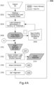
- Fig. 4 shows a flow chart representative of an exemplary method used to assist during installation and to evaluate the connector insertion loss.
- the process shown in Fig. 4 starts in step 300 when the equipment is turned on by the operator.
- the apparatus runs an initialization routine which includes checking the proper operation of its electronic components such as microcontroller, camera, laser output level, flash memory, etc.
- the main parameters used in the algorithms of the method are loaded into local memory.
- These parameters can include variable assignation for each type of connectors, calibration constants, default resolution of the camera, default exposure time, default gain, default frame rate, noise thresholds, x-y coordinate for locations in the sensor to compute dark current, x-y coordinate for reference points in the sensor, decision threshold for image localization, decision thresholds for tilt correction, initial scaling factors, decision thresholds for RTC acceptance for each type of connector, decision and threshold factors for illumination, sleeping time constants, variables for maximum number of iterations in RTC process, and many others.
- the apparatus displays a message indicating the apparatus is ready for operation and provides the operator with the option to change default values such as connector type, pass/fail spec limits, or other relevant parameters.
- the operator uses an input device to change one or more default parameters.
- the operator receives a display message to insert the pre-terminated optical connector and connect the optical source to the connector ferrule. At this point, the user also has the option to terminate the process.
- the apparatus runs algorithm A1, which checks the environmental ambient illumination levels without laser illumination, and compares levels to threshold levels already loaded in 304. This is done by measuring the background levels of ambient light reaching the sensor. If the measurement is greater than a specified threshold, the apparatus outputs a message indicating that a cover is needed to shade the connector (or ambient light needs to be reduced in some other manner) in order to accurately estimate low insertion loss values. Under most operating conditions of at least 1500 lux for indoor illumination (fluorescent or LED lighting devices), the threshold value is high enough to enable operation without a cover.
- the apparatus runs algorithm A1, which checks the background noise in non-illuminated areas of the sensor.
- the noise level of the optical imaging system is estimated by analyzing a small region of the sensor that is not illuminated by external optical sources. Then, the maximum and standard deviation of the noise, as well as the histogram is estimated. The noise is recorded as a variable, i.e., NOISE_TH, in memory and used by other algorithms as a threshold to clean the image.
- step 318 the position, tilt and scale factors of the connector image in the sensor are estimated using algorithm A3.
- algorithm A3 the mechanical tolerances of the apparatus such as lateral and angular offsets, height, sensor and lens relative position, length defocus, and scaling factors can be relaxed.
- the self-alignment algorithm represented in the flow chart of Fig. 5 , is used to locate the position of the connector image on the sensor, correct for any lateral offsets or axial tilt, and estimates the visual magnification of the object with respect to its image in the sensor.
- the parameters obtained from this algorithm are required for the subsequent algorithms shown in the chart of Fig. 4 for accurate image analysis and connector performance estimation.
- step 400 the noise of the sensor, NOISE_TH, which was estimated during the execution of algorithm A2, is used to determine a threshold required to identify the location of the connector in the sensor, labeled here THRESHOLD_P0.
- a factory calibration factor (loaded in step 304) can be used to multiply the parameter NOISE_TH.
- step 402 the camera is set to the maximum exposure time and in step 404 two images are captured.
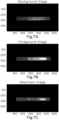
- the first image is acquired with the optical source turned off. This image is labeled background image.
- the second image capture occurs with the optical source turned on.
- the later image is labeled foreground image.
- the background image is subtracted from the foreground image resulting in a resultant image.
- An example of each of these images is shown in Fig. 7 .
- step 406 the effects of noise in the image analysis are minimized by setting all pixels with level values below the NOISE_TH to zero.
- An example of the PV ( y ) calculation is shown in Fig. 8 .
- cent_ y is used to select the region of interest (ROI) in the sensor that covers the image of the connector along the y -axis. This reduces the number of y -axis pixels to be utilized in the subsequent computations. For example, for a sensor with 640x480 pixels, after the y- axis ROI is found, only 640 ⁇ 100 pixels are used.
- the profile average of the image is computed using: PA x ⁇ mean y I ROI x y where, I ROI ( x , y ) is now the ROI selected from the sensor image.
- the start and end of the connector image is computed using the following procedure:
- centroid x ⁇ y y image _ h y x ⁇ y image _ h y x
- width x ⁇ y y ⁇ centroid x 2 image _ h y x ⁇ y image _ h y x
- the ratio of n_pixels with a design parameter loaded in 304 are used to computer the scaling factor.
- scaling _ factor n _ pixels n _ ref
- the value of the design parameter assumes an apparatus with tight tolerances, where the image is in focus.
- the scaling factor is stored and to be used by the RTC and IL algorithms (A6 and A7).
- the next steps which is the tilt estimation algorithm, it is assumed that the object plane is tilted with respect of the sensor plane as shown in Fig. 9 .
- This figure shows the centroid(x) and width(x) computed in 416.
- step 422 if the tilt angle is larger than a maximum tilt angle, a flag variable, FLAG_ANGLE_CORRECT, is turned on. This flag will be used in algorithm A4; when ON it will correct for the tilt, if OFF it will not make a correction.
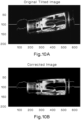
- step 424 if FLAG_ANGLE_CORRECT is turned on, the image will be corrected. This is an optional step to show the degree of correction before the termination of the connector is performed. Fig. 10 shows and example of tilt correction.
- step 426 the algorithm ends and returns to the general flow chart shown in Fig. 4 and to step 320.
- the apparatus runs algorithm A4 which captures images with corrected background and enhanced dynamic range.
- image processing is required to extract the information from the acquired images in order to predict if the connector is ready to be terminated while the fiber is inserted, and after termination, to estimate the IL.
- an uncooled B&W CMOS camera with relative low resolution e.g., 640x480 pixels, may be utilized.
- the effective number of bits per pixel is relative low (e.g., 8 bits).
- the algorithm illustrated by way of a flow chart in Fig. 6 is able to efficiently extract key information from the images captured by the camera. This information is used later for the ready to cam algorithm (RTC, A6) and for the IL estimation (algorithm A7).
- Fig. 6 shows the flow diagram algorithm A4.
- the algorithm finds the best exposure time that sets the levels inside the range of pixel levels obtained in step 300 of Fig. 4 .
- the range of levels can be 200 to 255.
- a correct execution of this step is important to the other algorithms since an incorrect exposure time will produce underexposed or saturated images.
- the algorithm follows an iterative cycle which continuously modifies the exposure based on current maximum values in the image. For example, the new exposure is obtaining by multiplying the current exposure by a factor that is directly proportional to the maximum pixel level (e.g., 255 for an eight-bit camera) and inversely proportional to the current maximum level.
- the image is captured in step 502. Since the apparatus performs real-time background subtraction in order to operate without a cover under most of the indoor illumination conditions, ideally at least two images are captured during this step. First, the optical source is turned off, and an image is acquired and labeled as background image. Next, the optical source is turned on and a second image, labeled foreground image, is acquired. Finally, the background image is subtracted from the foreground image. As a result of this processing, the impact of the environmental lighting is reduced or minimized. The resultant image is labeled low exposure image.
- step 504 the exposure is set to the maximum value which, in most cases, produces saturation in at least one pixel.
- step 506 the resultant image is captured in a similar way as described above for the low exposure image.
- the light source is turned off to capture a background image and turned on to capture a foreground image.
- the images are subtracted and the resultant image is stored and labeled high exposure image.
- step 508 both images are combined to produce an image with high dynamic range.
- the algorithm can use the following equation for the combination: where, I c ( x, y ) is the image array in the apparatus's memory, ⁇ LOW and ⁇ HIGH are the low exposure time (obtained in step 500), and the highest exposure time of the camera respectively.
- Threshold_comb is a predefined parameter loaded in step 300 of Fig 3 , which depends on the camera characteristics. An example for this combination is shown in Fig 12 .
- step 512 the algorithm corrects for the misalignment detected by algorithm A3. For example, if there is a tilt in the image and if FLAG_ANGLE_CORRECT is ON, (see algorithm A3) the image is corrected. Fig. 10 shows an example for this correction.
- step 514 the image is reduced from a 2-dimensional array to a one-dimensional array or vector, denominated here as a profile. This reduction is done to enable real-time computations of RTC and IL algorithms without requiring an expensive and/or power consuming processor. The profile shown in Fig.
- the profiles are stored in memory and in step 516, and the A4 algorithm ends and return control to other processes as shown in Fig.4 .
- step 322 algorithm A5 runs a check to determine if the optical source is sufficiently coupled to the connector under test. Insufficient optical coupling results in a low signal-to-noise ratio (SNR) and inaccurate IL estimations.
- SNR signal-to-noise ratio
- this algorithm evaluates the ratio of intensity levels of different regions of the connector. In order to estimate these ratios, it uses the profiles, PA and PM stored in memory from previous steps in the general method. As an example, the following equations can be used for the computation of ratios:
- the position of the regions B and C are obtained from pre-loaded tables (obtained in step 304) for the type of connector.
- pre-loaded tables obtained in step 304.
- the ratios are computed using equations (11) and (12) they are compared with pre-loaded thresholds. Depending on the comparison it will be determined if the connection between the launch fiber and the field connector is sufficiently good. If the connection is sufficiently good, a flag variable will be activated and a message can be displayed to show the status of the connection. Otherwise, a message to disconnect the source and clean may be displayed.
- step 328 the apparatus saves the profiles obtained in step 320 as initial connector profiles.
- the average maximum profiles at this step will be saved as PAl(x) and PM2(x).
- step 330 the operator receives a message to insert the prepared field fiber into the connector and upon insertion of the connector, the apparatus continues the RTC algorithm A6 in steps 332 to 338.
- algorithm A6 is designed to assist the operator during the termination process. It outputs an indicator when the connector is ready to be cammed such that the splice is completed.
- algorithm A4 is called to process the image and provide the profiles, PA ( x ) and PM ( x ) . As explained earlier, algorithm A4 will capture, correct for background illumination, correct for misalignments, and enhance the dynamic range before returning the profiles.
- step 334 the centroids of both profiles and their ratios for certain regions are computed in a similar way as described in algorithm A5.
- the regions of importance for the RTC algorithm are preloaded for each connector type, e.g., LC or SC. These regions may be determined from statistical analysis of a large population of connectors.
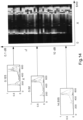
- Fig. 13 shows an example for 4 SC connectors labeled SC1 - SC4.
- Fig. 13 Three stages of the RTC image analysis are shown in Fig. 13 .
- the field fiber is only partially inserted and the connector is not ready to be cammed, avoiding a high IL (> 1dB) condition.
- the field fiber is in close proximity to the internal stub fiber, but not yet in the optimum position.
- the images show when the field fiber is fully inserted and in physical contact with the internal stub fiber. Once this condition is achieved, the connector is ready to be cammed. For a connector cammed during this condition, there is a high likelihood that that the IL is very low (e.g., ⁇ 0.3 dB).
- Figure 13 also shows that the peak levels of the radiation patterns shift from region C to D as the field fiber approaches the stub fiber. This visual effect can be quantified with the centroid of the image or with the ratio of average levels between regions C and D.
- the computational method for the later metric is given by:
- the apparatus can communicate real time values of the ratio or centroid by transmitting the calculated numerical values or pictorial representations to a display, in the form of graphical images or progress bars.
- the algorithm compares the ratios and centroid with preloaded thresholds (loaded in 304 for the type of connector). This threshold may come from a statistical analysis for each type of connector. If the centroid is higher than the centroid threshold and the RTC condition is achieved, the algorithm will proceed to step 340. Otherwise, it will return to step 332 and the RTC cycle will repeat.
- the profiles are stored as PA2 ( x ) and PM2 ( x ) and thereafter in step 342 a message and/or image can be displayed indicating that the connector termination can be completed by camming or rotating the mechanical splice mechanism. Once done so, the RTC process is ended in step 344 with the last profile from the RTC process being stored in step 346.
- step 348 algorithm A5 again verifies that the optical source is properly coupled to the connector. If not, a flag variable is activated and a message is displayed instructing the user to reposition and or clean the mating points. If algorithm A5 verifies a properly coupled optical source, step 352 captures and stores a new set of IL profiles. Then, in step 354 the connector parameters,
- step 356 algorithm A7 is executed to estimate the IL of the connector.
- This algorithm is utilized to estimate IL based on captured images at different stage of the installation process.
- the algorithm is based on statistical studies of a large population of connectors of different types, such as LC and SC for single-mode and multimode connectors.
- the insertion loss value determined pursuant to this algorithm will be estimated using: IL Est ⁇ ⁇ 10 K _ IL 1 log 10 1 ⁇ K _ IL 2 SumC 3 ⁇ K _ IL 3 SumB 3 max SumC 1 SumC 2 ⁇ K _ IL 4 SumB 1 + K _ IL 0 + K _ IL 5 SumC 3 SumB 3
- K_IL1 , K_IL , K_IL2 , K_IL3 , K_IL4 , and K_IL5 are factory calibration factors loaded in step 304
- i is an index that can take values from 1 to 3.
- step 358 the value returned by algorithm A7 is compared against the specified limit from default tables loaded in step 302, or against values entered by the operator in step 308. If the IL is lower than the specified limit (e.g., 0.75dB) a true logic condition is generated and pass indicator 362 will be displayed along with the estimated IL value on the display screen. If a false condition occurs, a "fail" message will be displayed in step 360.
- the IL results are saved in step 364 and the process ends at step 366 where the tool enters a "Tool Ready” stage essentially equivalent to the stage after step 306. In the latter case, the process proceeds directly to step 366.
- the profiles at three stages of the installation, as well as the IL and time are saved. This information can be used later for statistical analysis.
- the advantage of saving the profiles instead of the images is that the memory requirements on the tool can be reduced at least 2 orders of magnitude and data transmission from apparatus to a mobile device can become faster.
- the disclosed apparatus can operate in stand-alone mode during the complete installation.
- the installer ID, time, location and profiles for each connector can be stored in the apparatus.
- the apparatus can include functionalities to connect to a mobile device in a wired or wireless configuration, e.g., Bluetooth.
- the mobile device can send data to update the tool tables and update the firmware among other functionalities.
- the mobile device can also upload the data stored in the tool or transmit to a centralized data base where analysis can be performed.
- a computer or mobile device with access to the aggregate data of one or more installation projects can analyze the data and provide valuable information to the installer, customer, or connector supplier to be used to improve:
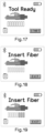
- Figs. 17 to 22 show some examples of the images to be displayed.
- Figs. 18 to 20 can show figures of the connector with a color bar indicator representing how close the field fiber is to the stub fiber. At the optimum position, the display will show (like in Fig. 21 ) that the fiber is ready to terminate or cam and it will show a message to rotate the connector.
- a sound from a speaker in the apparatus or a headphone (wired or wireless) connected to the apparatus can emit a sound to indicate if the connector is ready to terminate.
- Fig. 22 shows an exemplary image of a display after the IL is estimated by the apparatus using algorithm A7 in step 356.
Landscapes
- Physics & Mathematics (AREA)
- Engineering & Computer Science (AREA)
- General Physics & Mathematics (AREA)
- Multimedia (AREA)
- Optics & Photonics (AREA)
- Signal Processing (AREA)
- Theoretical Computer Science (AREA)
- Analytical Chemistry (AREA)
- Chemical & Material Sciences (AREA)
- Computer Vision & Pattern Recognition (AREA)
- Quality & Reliability (AREA)
- Software Systems (AREA)
- Mechanical Coupling Of Light Guides (AREA)
- Testing Of Optical Devices Or Fibers (AREA)
- Length Measuring Devices By Optical Means (AREA)
- Studio Devices (AREA)
Claims (2)
- Testverfahren zur Beurteilung des optischen Einfügeverlusts einer mechanischen Spleißverbindung zweier optischer Fasern (101, 102), umfassend:Verwenden eines Geräts, umfassend eine Laserquelle (202), digitale Videokamera (205), einen Mikrocontroller oder Prozessor (206), elektronische Schaltung(en), residenten Speicher und Mittel zum Koppeln des Laserausgangssignals an eine der zu spleißenden optischen Fasern;Erlangen und Analysieren von digitalen Videobildern des gestreuten Lichts aus mindestens einem Abschnitt von einer optischen Faser und der mechanischen Spleißverbindung unter Verwendung von eingebetteten Algorithmen, um die Qualität der mechanischen Spleißung zu bestimmen;Bereitstellen von dynamischer Reichweitenverbesserung des Kamerasensors, und Bereitstellen von Hintergrundsubtraktion von Umgebungslicht, um die Schätzung des optischen Einfügeverlusts der mechanischen Spleißverbindung basierend auf Echtzeitbildanalyse der mechanischen Spleißverbindung zu verbessern;Bereitstellen einer numerischen, bildlichen oder akustischen Angabe (208, 210) von bestanden/nichtbestanden an der optimalen Position, um die Spleißverbindung zu terminieren, um einer Bedienungsperson während des Terminierungsprozesses der Spleißverbindung zu assistieren; undSchätzen des optischen Einfügeverlusts der mechanischen Spleißverbindung basierend auf den erlangten Bildern,dadurch gekennzeichnet, dass das Bereitstellen von dynamischer Reichweitenverbesserung des Kamerasensors einen Algorithmus umfasst, der die folgenden Schritte umfasst:Bestimmen einer optimalen Belichtungszeit für das Erlangen der Bilder;Aufnehmen eines Hintergrundbildes der mechanischen Spleißverbindung mit abgeschalteter Laserquelle;Aufnehmen eines Vordergrundbildes der mechanischen Spleißverbindung mit eingeschalteter Laserquelle;Subtrahieren des Hintergrundbildes von dem Vordergrundbild, um ein resultierendes Bild zu erhalten; Schätzen eines Rauschpegels durch Analysieren eines Areals eines Sensors, das nicht von externen Quellen beleuchtet wird, und Reduzieren der Auswirkung des Rauschens durch Nullen der Pixel mit Pegelwerten unterhalb des geschätzten Rauschpegels in dem resultierenden Bild;Schätzen einer Kippung und Korrigieren der Kippung in dem resultierenden Bild; undReduzieren des resultierenden Bildes von einem 2-dimensionalen Array auf ein eindimensionales Array oder einen Vektor.
- Verfahren nach Anspruch 1, wobei eine Serie von Geräuschen mit unterschiedlicher Tonhöhe durch einen Lautsprecher, Signalgeber oder drahtlosen Kopfhörer (210) produziert wird, um während des Terminierungsprozesses zu assistieren.
Applications Claiming Priority (3)
| Application Number | Priority Date | Filing Date | Title |
|---|---|---|---|
| US201662370379P | 2016-08-03 | 2016-08-03 | |
| US15/658,565 US10984519B2 (en) | 2016-08-03 | 2017-07-25 | Method for evaluating the optical insertion loss of a mechanical splice joint of two optical fibers |
| PCT/US2017/044079 WO2018026618A1 (en) | 2016-08-03 | 2017-07-27 | Methods and devices for evaluating optical fiber splices |
Publications (2)
| Publication Number | Publication Date |
|---|---|
| EP3494426A1 EP3494426A1 (de) | 2019-06-12 |
| EP3494426B1 true EP3494426B1 (de) | 2024-10-02 |
Family
ID=61069575
Family Applications (1)
| Application Number | Title | Priority Date | Filing Date |
|---|---|---|---|
| EP17749062.0A Active EP3494426B1 (de) | 2016-08-03 | 2017-07-27 | Verfahren und vorrichtungen zur beurteilung von glasfaserspleissungen |
Country Status (8)
| Country | Link |
|---|---|
| US (2) | US10984519B2 (de) |
| EP (1) | EP3494426B1 (de) |
| JP (1) | JP7128176B2 (de) |
| KR (1) | KR102454883B1 (de) |
| CN (1) | CN109564331B (de) |
| MX (1) | MX2019000988A (de) |
| TW (1) | TWI732011B (de) |
| WO (1) | WO2018026618A1 (de) |
Families Citing this family (7)
| Publication number | Priority date | Publication date | Assignee | Title |
|---|---|---|---|---|
| US10260989B2 (en) * | 2016-08-26 | 2019-04-16 | Corning Optical Communications LLC | Devices, systems, and methods for checking the continuity of at least one splice within a fiber optic connector |
| US10636134B2 (en) * | 2018-09-07 | 2020-04-28 | Fluke Corporation | Display apparatus and method for optical fiber inspection |
| USD895642S1 (en) | 2018-09-07 | 2020-09-08 | Fluke Corporation | Display screen or portion thereof with graphical user interface for fiber optic cable inspection |
| USD912083S1 (en) * | 2019-08-01 | 2021-03-02 | Facebook, Inc. | Display screen or portion thereof with graphical user interface |
| US11797880B1 (en) | 2019-08-27 | 2023-10-24 | Meta Platforms, Inc. | Systems and methods for digital content provision |
| CN113884001B (zh) * | 2021-06-21 | 2023-01-24 | 荣耀终端有限公司 | 终端内导光柱装配状态检测装置及检测方法 |
| US12009117B2 (en) | 2022-05-16 | 2024-06-11 | Panduit Corp. | Hybrid fiber optic and electrical connector |
Citations (1)
| Publication number | Priority date | Publication date | Assignee | Title |
|---|---|---|---|---|
| US9325906B2 (en) * | 2013-10-18 | 2016-04-26 | The Lightco Inc. | Methods and apparatus relating to a thin camera device |
Family Cites Families (25)
| Publication number | Priority date | Publication date | Assignee | Title |
|---|---|---|---|---|
| US5278932A (en) * | 1992-09-30 | 1994-01-11 | At&T Bell Laboratories | Optical fiber splice verification system |
| SE516153C2 (sv) * | 1997-02-14 | 2001-11-26 | Ericsson Telefon Ab L M | Förfarande och anordning vid hopsvetsning av optiska fibrer |
| JP3443349B2 (ja) * | 1998-03-18 | 2003-09-02 | 古河電気工業株式会社 | 光ファイバ観察用画像処理装置 |
| US6816661B1 (en) | 2000-03-22 | 2004-11-09 | Corning Cable Systems Llc | Multifiber connector, installation tool and associated methods of validating optical fiber continuity |
| JP2003214978A (ja) * | 2002-01-18 | 2003-07-30 | Tokyo Seimitsu Co Ltd | 光コネクタ端面検査装置 |
| US6677591B1 (en) * | 2002-01-30 | 2004-01-13 | Ciena Corporation | Method and system for inspecting optical devices |
| SE522255C2 (sv) * | 2002-02-26 | 2004-01-27 | Ericsson Telefon Ab L M | Anordning och förfarande för smältskarvning av ändar av två optiska fibrer |
| BR0316855A (pt) * | 2002-12-05 | 2006-10-03 | Ericsson Telefon Ab L M | método e arranjo para calibrar temperatura de fusão em um dispositivo de emenda de fibra óptica |
| US6984077B2 (en) | 2003-03-25 | 2006-01-10 | Aurora Instruments, Inc. | System for joining polarization-maintaining optical fiber waveguides |
| JP2007525858A (ja) * | 2003-04-15 | 2007-09-06 | センサーズ・フォー・メデセン・アンド・サイエンス・インコーポレーテッド | 一体化されたアンテナを備えたプリント回路装置及びプリント集積回路基板アンテナを備えた埋め込み可能なセンサー処理装置 |
| JP4610186B2 (ja) * | 2003-12-26 | 2011-01-12 | 渡辺電機工業株式会社 | ヘッドライトテスターの光度測定方法とその装置 |
| US7192195B2 (en) * | 2005-07-29 | 2007-03-20 | Corning Cable Systems Llc | Methods and apparatus for estimating optical insertion loss |
| WO2007013551A1 (ja) * | 2005-07-29 | 2007-02-01 | Olympus Corporation | 光強度測定方法および光強度測定装置 |
| US8094988B2 (en) * | 2005-12-15 | 2012-01-10 | Corning Cable Systems Llc | Apparatus and methods for verifying an acceptable splice termination |
| US7680384B2 (en) | 2006-01-26 | 2010-03-16 | Corning Cable Systems Llc | Installation tool with integrated visual fault indicator for field-installable mechanical splice connector |
| JP2009146367A (ja) | 2007-12-14 | 2009-07-02 | Toru Amamiya | 診療情報、禁忌薬情報や個人特定情報をicチップ式会員カードの電子情報保存領域に書込み、医療機関先で容易に閲覧確認、変更可能とした上で、個人非特定情報のみを外部公開データベースに格納することで、悪意のある第三者よりのデータベース情報漏洩があった場合も個人非特定情報のみの漏洩に止め、会員の個人情報保護を可能とするシステム。 |
| US8665350B2 (en) * | 2008-05-08 | 2014-03-04 | Altasens, Inc. | Method for fixed pattern noise (FPN) correction |
| WO2009146367A1 (en) * | 2008-05-29 | 2009-12-03 | Panduit Corp. | Method and apparatus for verifying the termination quality of an optical fiber interface in a fiber optic cable connector |
| US20110146071A1 (en) * | 2008-10-06 | 2011-06-23 | Afl Telecommunications Llc | Thermal rounding shaped optical fiber for cleaving and splicing |
| EP2837072B1 (de) | 2012-04-12 | 2020-12-23 | Fraunhofer Gesellschaft zur Förderung der Angewand | Verfahren und vorrichtung zur reduktion von modeninstabilität in einem lichtwellenleiter |
| GB2513343A (en) * | 2013-04-23 | 2014-10-29 | Univ Singapore | Methods related to instrument-independent measurements for quantitative analysis of fiber-optic Raman spectroscopy |
| US10060826B2 (en) * | 2012-11-20 | 2018-08-28 | Panduit Corp. | Optical fiber mechanical splice termination and test apparatus and methods |
| US8967478B2 (en) * | 2013-05-16 | 2015-03-03 | Symbol Technologies, Inc. | Apparatus for and method of electro-optically reading a target in the presence of ambient light by rejecting the ambient light |
| EP3058416B1 (de) * | 2013-10-18 | 2019-11-20 | Light Labs Inc. | Verfahren und vorrichtung zur implementierung und/oder verwendung einer kameravorrichtung |
| US20160133005A1 (en) * | 2014-11-10 | 2016-05-12 | Panduit Corp. | Apparatus and method for terminating and testing connectors |
-
2017
- 2017-07-25 US US15/658,565 patent/US10984519B2/en active Active
- 2017-07-27 CN CN201780048174.7A patent/CN109564331B/zh active Active
- 2017-07-27 JP JP2019505371A patent/JP7128176B2/ja active Active
- 2017-07-27 WO PCT/US2017/044079 patent/WO2018026618A1/en not_active Ceased
- 2017-07-27 MX MX2019000988A patent/MX2019000988A/es unknown
- 2017-07-27 KR KR1020197005609A patent/KR102454883B1/ko active Active
- 2017-07-27 EP EP17749062.0A patent/EP3494426B1/de active Active
- 2017-08-01 TW TW106125930A patent/TWI732011B/zh active
-
2021
- 2021-04-19 US US17/233,991 patent/US11625823B2/en active Active
Patent Citations (1)
| Publication number | Priority date | Publication date | Assignee | Title |
|---|---|---|---|---|
| US9325906B2 (en) * | 2013-10-18 | 2016-04-26 | The Lightco Inc. | Methods and apparatus relating to a thin camera device |
Also Published As
| Publication number | Publication date |
|---|---|
| CN109564331A (zh) | 2019-04-02 |
| JP2019528439A (ja) | 2019-10-10 |
| TWI732011B (zh) | 2021-07-01 |
| US20180040117A1 (en) | 2018-02-08 |
| US11625823B2 (en) | 2023-04-11 |
| US20210241448A1 (en) | 2021-08-05 |
| WO2018026618A1 (en) | 2018-02-08 |
| EP3494426A1 (de) | 2019-06-12 |
| MX2019000988A (es) | 2019-07-04 |
| US10984519B2 (en) | 2021-04-20 |
| JP7128176B2 (ja) | 2022-08-30 |
| CN109564331B (zh) | 2022-01-04 |
| TW201823783A (zh) | 2018-07-01 |
| KR20190034275A (ko) | 2019-04-01 |
| KR102454883B1 (ko) | 2022-10-14 |
Similar Documents
| Publication | Publication Date | Title |
|---|---|---|
| US11625823B2 (en) | Method for evaluating the optical loss of a mechanical splice joint of two optical fibers | |
| US20180350061A1 (en) | Apparatus and Method for Terminating and Testing Connectors | |
| US7192195B2 (en) | Methods and apparatus for estimating optical insertion loss | |
| AU2006333352A1 (en) | Apparatus and methods for verifying an acceptable splice termination | |
| US11982844B2 (en) | Method for estimating orientation of optical fiber and method for manufacturing optical-fiber component | |
| US20230228648A1 (en) | Apparatus and System for Visual Inspection of Fiber Ends and Image Analysis Tool for Detecting Contamination | |
| EP3704462B1 (de) | Verfahren zur herstellung eines optischen faserabschlusses unter verwendung einer referenzquelle | |
| CN107040307B (zh) | 用于智能检查的测试探针 | |
| KR101735356B1 (ko) | 광커넥터의 비접촉식 삽입손실 측정장치 및 그 측정방법 | |
| EP3121581B1 (de) | Messanordnung zur bestimmung der qualität eines optischen kabels und eines optischen verbinders in einem montierten zustand | |
| Lee et al. | Analysis and Evaluation of Slanted-edge-based Modulation Transfer Function and Focus Measurements for Optimal Assembly of Imaging Modules in Gastrointestinal Endoscopy |
Legal Events
| Date | Code | Title | Description |
|---|---|---|---|
| STAA | Information on the status of an ep patent application or granted ep patent |
Free format text: STATUS: UNKNOWN |
|
| STAA | Information on the status of an ep patent application or granted ep patent |
Free format text: STATUS: THE INTERNATIONAL PUBLICATION HAS BEEN MADE |
|
| PUAI | Public reference made under article 153(3) epc to a published international application that has entered the european phase |
Free format text: ORIGINAL CODE: 0009012 |
|
| STAA | Information on the status of an ep patent application or granted ep patent |
Free format text: STATUS: REQUEST FOR EXAMINATION WAS MADE |
|
| 17P | Request for examination filed |
Effective date: 20190204 |
|
| AK | Designated contracting states |
Kind code of ref document: A1 Designated state(s): AL AT BE BG CH CY CZ DE DK EE ES FI FR GB GR HR HU IE IS IT LI LT LU LV MC MK MT NL NO PL PT RO RS SE SI SK SM TR |
|
| AX | Request for extension of the european patent |
Extension state: BA ME |
|
| DAV | Request for validation of the european patent (deleted) | ||
| DAX | Request for extension of the european patent (deleted) | ||
| STAA | Information on the status of an ep patent application or granted ep patent |
Free format text: STATUS: EXAMINATION IS IN PROGRESS |
|
| 17Q | First examination report despatched |
Effective date: 20211013 |
|
| GRAP | Despatch of communication of intention to grant a patent |
Free format text: ORIGINAL CODE: EPIDOSNIGR1 |
|
| STAA | Information on the status of an ep patent application or granted ep patent |
Free format text: STATUS: GRANT OF PATENT IS INTENDED |
|
| INTG | Intention to grant announced |
Effective date: 20240522 |
|
| GRAS | Grant fee paid |
Free format text: ORIGINAL CODE: EPIDOSNIGR3 |
|
| GRAA | (expected) grant |
Free format text: ORIGINAL CODE: 0009210 |
|
| STAA | Information on the status of an ep patent application or granted ep patent |
Free format text: STATUS: THE PATENT HAS BEEN GRANTED |
|
| AK | Designated contracting states |
Kind code of ref document: B1 Designated state(s): AL AT BE BG CH CY CZ DE DK EE ES FI FR GB GR HR HU IE IS IT LI LT LU LV MC MK MT NL NO PL PT RO RS SE SI SK SM TR |
|
| REG | Reference to a national code |
Ref country code: GB Ref legal event code: FG4D |
|
| REG | Reference to a national code |
Ref country code: CH Ref legal event code: EP |
|
| REG | Reference to a national code |
Ref country code: IE Ref legal event code: FG4D |
|
| REG | Reference to a national code |
Ref country code: DE Ref legal event code: R096 Ref document number: 602017085210 Country of ref document: DE |
|
| REG | Reference to a national code |
Ref country code: LT Ref legal event code: MG9D |
|
| REG | Reference to a national code |
Ref country code: NL Ref legal event code: MP Effective date: 20241002 |
|
| REG | Reference to a national code |
Ref country code: AT Ref legal event code: MK05 Ref document number: 1728901 Country of ref document: AT Kind code of ref document: T Effective date: 20241002 |
|
| PG25 | Lapsed in a contracting state [announced via postgrant information from national office to epo] |
Ref country code: NL Free format text: LAPSE BECAUSE OF FAILURE TO SUBMIT A TRANSLATION OF THE DESCRIPTION OR TO PAY THE FEE WITHIN THE PRESCRIBED TIME-LIMIT Effective date: 20241002 |
|
| PG25 | Lapsed in a contracting state [announced via postgrant information from national office to epo] |
Ref country code: NL Free format text: LAPSE BECAUSE OF FAILURE TO SUBMIT A TRANSLATION OF THE DESCRIPTION OR TO PAY THE FEE WITHIN THE PRESCRIBED TIME-LIMIT Effective date: 20241002 |
|
| PG25 | Lapsed in a contracting state [announced via postgrant information from national office to epo] |
Ref country code: IS Free format text: LAPSE BECAUSE OF FAILURE TO SUBMIT A TRANSLATION OF THE DESCRIPTION OR TO PAY THE FEE WITHIN THE PRESCRIBED TIME-LIMIT Effective date: 20250202 Ref country code: PT Free format text: LAPSE BECAUSE OF FAILURE TO SUBMIT A TRANSLATION OF THE DESCRIPTION OR TO PAY THE FEE WITHIN THE PRESCRIBED TIME-LIMIT Effective date: 20250203 Ref country code: HR Free format text: LAPSE BECAUSE OF FAILURE TO SUBMIT A TRANSLATION OF THE DESCRIPTION OR TO PAY THE FEE WITHIN THE PRESCRIBED TIME-LIMIT Effective date: 20241002 |
|
| PG25 | Lapsed in a contracting state [announced via postgrant information from national office to epo] |
Ref country code: FI Free format text: LAPSE BECAUSE OF FAILURE TO SUBMIT A TRANSLATION OF THE DESCRIPTION OR TO PAY THE FEE WITHIN THE PRESCRIBED TIME-LIMIT Effective date: 20241002 |
|
| PG25 | Lapsed in a contracting state [announced via postgrant information from national office to epo] |
Ref country code: BG Free format text: LAPSE BECAUSE OF FAILURE TO SUBMIT A TRANSLATION OF THE DESCRIPTION OR TO PAY THE FEE WITHIN THE PRESCRIBED TIME-LIMIT Effective date: 20241002 |
|
| PG25 | Lapsed in a contracting state [announced via postgrant information from national office to epo] |
Ref country code: ES Free format text: LAPSE BECAUSE OF FAILURE TO SUBMIT A TRANSLATION OF THE DESCRIPTION OR TO PAY THE FEE WITHIN THE PRESCRIBED TIME-LIMIT Effective date: 20241002 |
|
| PG25 | Lapsed in a contracting state [announced via postgrant information from national office to epo] |
Ref country code: NO Free format text: LAPSE BECAUSE OF FAILURE TO SUBMIT A TRANSLATION OF THE DESCRIPTION OR TO PAY THE FEE WITHIN THE PRESCRIBED TIME-LIMIT Effective date: 20250102 |
|
| PG25 | Lapsed in a contracting state [announced via postgrant information from national office to epo] |
Ref country code: LV Free format text: LAPSE BECAUSE OF FAILURE TO SUBMIT A TRANSLATION OF THE DESCRIPTION OR TO PAY THE FEE WITHIN THE PRESCRIBED TIME-LIMIT Effective date: 20241002 Ref country code: AT Free format text: LAPSE BECAUSE OF FAILURE TO SUBMIT A TRANSLATION OF THE DESCRIPTION OR TO PAY THE FEE WITHIN THE PRESCRIBED TIME-LIMIT Effective date: 20241002 Ref country code: GR Free format text: LAPSE BECAUSE OF FAILURE TO SUBMIT A TRANSLATION OF THE DESCRIPTION OR TO PAY THE FEE WITHIN THE PRESCRIBED TIME-LIMIT Effective date: 20250103 |
|
| PG25 | Lapsed in a contracting state [announced via postgrant information from national office to epo] |
Ref country code: CZ Free format text: LAPSE BECAUSE OF FAILURE TO SUBMIT A TRANSLATION OF THE DESCRIPTION OR TO PAY THE FEE WITHIN THE PRESCRIBED TIME-LIMIT Effective date: 20241002 Ref country code: PL Free format text: LAPSE BECAUSE OF FAILURE TO SUBMIT A TRANSLATION OF THE DESCRIPTION OR TO PAY THE FEE WITHIN THE PRESCRIBED TIME-LIMIT Effective date: 20241002 |
|
| PG25 | Lapsed in a contracting state [announced via postgrant information from national office to epo] |
Ref country code: RS Free format text: LAPSE BECAUSE OF FAILURE TO SUBMIT A TRANSLATION OF THE DESCRIPTION OR TO PAY THE FEE WITHIN THE PRESCRIBED TIME-LIMIT Effective date: 20250102 |
|
| PG25 | Lapsed in a contracting state [announced via postgrant information from national office to epo] |
Ref country code: SM Free format text: LAPSE BECAUSE OF FAILURE TO SUBMIT A TRANSLATION OF THE DESCRIPTION OR TO PAY THE FEE WITHIN THE PRESCRIBED TIME-LIMIT Effective date: 20241002 |
|
| REG | Reference to a national code |
Ref country code: DE Ref legal event code: R097 Ref document number: 602017085210 Country of ref document: DE |
|
| PG25 | Lapsed in a contracting state [announced via postgrant information from national office to epo] |
Ref country code: DK Free format text: LAPSE BECAUSE OF FAILURE TO SUBMIT A TRANSLATION OF THE DESCRIPTION OR TO PAY THE FEE WITHIN THE PRESCRIBED TIME-LIMIT Effective date: 20241002 |
|
| PG25 | Lapsed in a contracting state [announced via postgrant information from national office to epo] |
Ref country code: EE Free format text: LAPSE BECAUSE OF FAILURE TO SUBMIT A TRANSLATION OF THE DESCRIPTION OR TO PAY THE FEE WITHIN THE PRESCRIBED TIME-LIMIT Effective date: 20241002 |
|
| PG25 | Lapsed in a contracting state [announced via postgrant information from national office to epo] |
Ref country code: RO Free format text: LAPSE BECAUSE OF FAILURE TO SUBMIT A TRANSLATION OF THE DESCRIPTION OR TO PAY THE FEE WITHIN THE PRESCRIBED TIME-LIMIT Effective date: 20241002 |
|
| PG25 | Lapsed in a contracting state [announced via postgrant information from national office to epo] |
Ref country code: SK Free format text: LAPSE BECAUSE OF FAILURE TO SUBMIT A TRANSLATION OF THE DESCRIPTION OR TO PAY THE FEE WITHIN THE PRESCRIBED TIME-LIMIT Effective date: 20241002 |
|
| PG25 | Lapsed in a contracting state [announced via postgrant information from national office to epo] |
Ref country code: IT Free format text: LAPSE BECAUSE OF FAILURE TO SUBMIT A TRANSLATION OF THE DESCRIPTION OR TO PAY THE FEE WITHIN THE PRESCRIBED TIME-LIMIT Effective date: 20241002 |
|
| PLBE | No opposition filed within time limit |
Free format text: ORIGINAL CODE: 0009261 |
|
| STAA | Information on the status of an ep patent application or granted ep patent |
Free format text: STATUS: NO OPPOSITION FILED WITHIN TIME LIMIT |
|
| PG25 | Lapsed in a contracting state [announced via postgrant information from national office to epo] |
Ref country code: SE Free format text: LAPSE BECAUSE OF FAILURE TO SUBMIT A TRANSLATION OF THE DESCRIPTION OR TO PAY THE FEE WITHIN THE PRESCRIBED TIME-LIMIT Effective date: 20241002 |
|
| 26N | No opposition filed |
Effective date: 20250703 |
|
| PGFP | Annual fee paid to national office [announced via postgrant information from national office to epo] |
Ref country code: DE Payment date: 20250729 Year of fee payment: 9 |
|
| PGFP | Annual fee paid to national office [announced via postgrant information from national office to epo] |
Ref country code: GB Payment date: 20250728 Year of fee payment: 9 |
|
| PGFP | Annual fee paid to national office [announced via postgrant information from national office to epo] |
Ref country code: FR Payment date: 20250728 Year of fee payment: 9 |
|
| REG | Reference to a national code |
Ref country code: CH Ref legal event code: H13 Free format text: ST27 STATUS EVENT CODE: U-0-0-H10-H13 (AS PROVIDED BY THE NATIONAL OFFICE) Effective date: 20260224 |
|
| PG25 | Lapsed in a contracting state [announced via postgrant information from national office to epo] |
Ref country code: LU Free format text: LAPSE BECAUSE OF NON-PAYMENT OF DUE FEES Effective date: 20250727 |
|
| REG | Reference to a national code |
Ref country code: BE Ref legal event code: MM Effective date: 20250731 |
|
| PG25 | Lapsed in a contracting state [announced via postgrant information from national office to epo] |
Ref country code: BE Free format text: LAPSE BECAUSE OF NON-PAYMENT OF DUE FEES Effective date: 20250731 |
|
| PG25 | Lapsed in a contracting state [announced via postgrant information from national office to epo] |
Ref country code: CH Free format text: LAPSE BECAUSE OF NON-PAYMENT OF DUE FEES Effective date: 20250731 |