EP3493873B1 - Defibrillator für minimalinvasive chirurgische eingriffe - Google Patents
Defibrillator für minimalinvasive chirurgische eingriffe Download PDFInfo
- Publication number
- EP3493873B1 EP3493873B1 EP17837722.2A EP17837722A EP3493873B1 EP 3493873 B1 EP3493873 B1 EP 3493873B1 EP 17837722 A EP17837722 A EP 17837722A EP 3493873 B1 EP3493873 B1 EP 3493873B1
- Authority
- EP
- European Patent Office
- Prior art keywords
- paddle
- conductive
- paddle head
- shaft
- elongated shaft
- Prior art date
- Legal status (The legal status is an assumption and is not a legal conclusion. Google has not performed a legal analysis and makes no representation as to the accuracy of the status listed.)
- Active
Links
Images



Classifications
-
- A—HUMAN NECESSITIES
- A61—MEDICAL OR VETERINARY SCIENCE; HYGIENE
- A61N—ELECTROTHERAPY; MAGNETOTHERAPY; RADIATION THERAPY; ULTRASOUND THERAPY
- A61N1/00—Electrotherapy; Circuits therefor
- A61N1/02—Details
- A61N1/04—Electrodes
- A61N1/05—Electrodes for implantation or insertion into the body, e.g. heart electrode
- A61N1/0587—Epicardial electrode systems; Endocardial electrodes piercing the pericardium
-
- A—HUMAN NECESSITIES
- A61—MEDICAL OR VETERINARY SCIENCE; HYGIENE
- A61N—ELECTROTHERAPY; MAGNETOTHERAPY; RADIATION THERAPY; ULTRASOUND THERAPY
- A61N1/00—Electrotherapy; Circuits therefor
- A61N1/02—Details
- A61N1/04—Electrodes
- A61N1/05—Electrodes for implantation or insertion into the body, e.g. heart electrode
- A61N1/0587—Epicardial electrode systems; Endocardial electrodes piercing the pericardium
- A61N1/0595—Temporary leads
-
- A—HUMAN NECESSITIES
- A61—MEDICAL OR VETERINARY SCIENCE; HYGIENE
- A61N—ELECTROTHERAPY; MAGNETOTHERAPY; RADIATION THERAPY; ULTRASOUND THERAPY
- A61N1/00—Electrotherapy; Circuits therefor
- A61N1/18—Applying electric currents by contact electrodes
- A61N1/32—Applying electric currents by contact electrodes alternating or intermittent currents
- A61N1/38—Applying electric currents by contact electrodes alternating or intermittent currents for producing shock effects
- A61N1/39—Heart defibrillators
-
- A—HUMAN NECESSITIES
- A61—MEDICAL OR VETERINARY SCIENCE; HYGIENE
- A61N—ELECTROTHERAPY; MAGNETOTHERAPY; RADIATION THERAPY; ULTRASOUND THERAPY
- A61N1/00—Electrotherapy; Circuits therefor
- A61N1/02—Details
- A61N1/04—Electrodes
- A61N1/05—Electrodes for implantation or insertion into the body, e.g. heart electrode
- A61N1/056—Transvascular endocardial electrode systems
- A61N1/0563—Transvascular endocardial electrode systems specially adapted for defibrillation or cardioversion
Definitions
- the present invention relates to defibrillation paddles. More particularly, the present invention relates to defibrillation paddles that are used during minimally invasive procedures wherein the defibrillation paddle is brought into direct contact with the tissue of the heart.
- Defibrillators are devices that are specifically designed to pass an electrical current into a patient's heart.
- Non-intrusive defibrillators have electrodes that attach to the skin of a patient.
- the non-intrusive defibrillators pass electricity through the body from one external point to another.
- Such non-intrusive defibrillators are used by rescue workers, paramedics and the like to revive a person whose heart has stopped. Since non-intrusive defibrillators pass electricity through the body, hoping to affect the heart, large electrical charges are used. These charges often cause the skin of the patient to burn at the areas where the defibrillator is attached to the body and where electricity passes into and out of the patient's body.
- Intrusive defibrillators are used by physicians primarily in the operating room of hospitals. During many surgical procedures, a patient's heart may be temporarily stopped. In such situations, the patient's blood flow is transferred to an external pump. Once the surgical procedure is complete, a defibrillator is commonly used to restart the heart. When the heart muscle itself is exposed, the paddle terminals of the defibrillator are touched directly to the heart muscle. A small jolt of electricity is then passed through the tissue of the heart muscle to restart the heart's beat. Since the electricity is being applied directly to the heart muscle, low currents of electricity are used. However, even these low currents of electricity can result in some heart muscle tissue becoming burned in the areas of contact with the defibrillator's paddles, especially if there is not good contact with the heart tissue.
- One way to reduce the potential of damage to the heart muscle is to use a defibrillation system that touches the heart with only a single paddle. If only one paddle touches the heart, it is easier for a physician to bring that single paddle into proper contact with the heart.
- defibrillator systems have been made that use only one paddle.
- a patient is laid upon a conductive pad.
- a single paddle is provided. Both the single paddle and the conductive pad are connected to the defibrillator.
- the single paddle is then touched to the tissue of the heart. Electricity passes through the heart, through the back of the body and to the conductive pad. Since only one paddle is used, the chances that one paddle will be poorly positioned is reduced by half, as compared to two paddle systems.
- Such prior art defibrillation systems are exemplified by Japanese Reference No.
- JP2001121885 entitled Defibrillating Electrode And Defibrillation System and U.S. Patent No. 8,452,393 to Epstein, entitled Defibrillation Paddle Structure And Its Associated Method Of Use.
- the largest contact area possible is desired. If only a small contact area exists, all of the electrical current passing into the heart is forced to pass through the small area of tissue in contact with the defibrillator paddle head. This concentrates the electricity and can cause tissue burning and damage to the heart tissue. A large area of contact is desired because it distributes the flow of electrical current and is, therefore, less likely to cause burning.
- the key to avoiding tissue damage made by a defibrillator paddle is to have uniform contact between the paddle and the tissue of the heart muscle. To further complicate matters, a physician may decide to shock the heart at a specific spot. That location may be on the top of the heart or along one of the sides of the heart.
- the doctor must maneuver the defibrillator paddle to that portion of the heart while still maintaining a flush contact between the defibrillator paddle and the tissue of the heart. If there is not a flush contact, the odds greatly increase that the defibrillator paddle may cause an electrical burn. Furthermore, without a flush contact, the defibrillator may fail to affect the heart muscle in the desired manner.
- the present invention is a defibrillation system with a defibrillation paddle assembly as claimed in the appended claims.
- the paddle assembly has a dielectric handle.
- the paddle assembly also has a paddle head with a conductive surface.
- the paddle head is introduced into the chest through a small surgical incision.
- the paddle head is manipulated until the conductive surface makes flush contact with the tissue of the heart.
- the paddle head is connected to the handle by an elongated shaft.
- the elongated shaft has an electrically conductive core that is covered in a dielectric insulator.
- the elongated shaft is malleable. This enables the elongated shaft to be configurable into different shapes by manual manipulation.
- a pivot connection joins one end of the elongated shaft to the paddle head.
- the pivot connection enables the paddle head to move through a range of different orientations with respect to the elongated shaft.
- the pivot connection also provides an electrical interconnection between the conductive core of the elongated shaft and the conductive surface of the paddle head.
- the electricity passes through the conductive core of the elongated shaft and into the paddle head.
- This configuration enables both the elongated shaft and the paddle head to be made very narrow.
- the overall system is well adapted for use with minimally invasive procedures, where only small incisions are made into a patient's body.
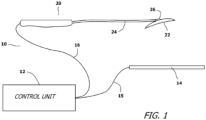
- a defibrillation system 10 in accordance with the present invention.
- the defibrillation system 10 consists of a control unit 12 that controls the electrical current and waveform that will be passed through the heart muscle.
- the control unit 12 has adjustable controls and safeguards typical in the industry.
- a conductive pad 14 is provided.
- the conductive pad 14 is connected to the control unit 12 by a first flexible terminal wire 15.
- a paddle assembly 20 is also attached to the control unit 12 by a second flexible terminal wire 16.
- the paddle assembly 20 has a conductive contact surface 22.
- the control unit 12 creates an electrical bias between the conductive contact surface 22 of the paddle assembly 20 and the conductive pad 14. Accordingly, when both the conductive pad 14 and the conductive contact surface 22 of the paddle assembly 20 are touched to a patient, electricity can flow through the patient between these surfaces. In common use, a patient would be placed atop the conductive pad 14.
- the paddle assembly 20 would be manipulated by a surgeon inside the body so that the conductive contact surface 22 touches heart tissue.
- the defibrillator system 10 is then activated so that an electrical current will pass through the heart and the portion of the body between the conductive contact surface 22 and the conductive pad 14.
- the conductive contact surface 22 is supported by the structure of a paddle head 26.
- the features of the paddle head 26 are later explained in greater detail.
- the paddle head 26 is set upon a malleable shaft 24.
- the malleable shaft 24 attaches the paddle head 26 to a handle 28.
- the handle 28 is ergonomically shaped to fit comfortably in a physician's hand. The physician using the paddle assembly 20 holds the paddle assembly 20 by grasping the handle 28.
- the paddle head 26 is attached to the malleable shaft 24 at a pivot joint 30.
- This enables the orientation of the paddle head 26 to be selectively altered relative the malleable shaft 24.
- the pivot joint 30 enables the orientation of the paddle head 26 to be altered.
- the paddle head 26 must be manually moved with a concerted effort.
- the pivot joint 30 is not so loose that gravity or slight contact alters the orientation of the paddle head 26. As such, the paddle head 26 remains in the orientation it is placed as it is advanced into the body and brought into contact with the heart.
- the malleable shaft 24 can be manually altered into different shapes and curvatures using a concerted manual effort.
- the malleable shaft 24 can be bent.
- the malleable shaft 24 is relatively stiff. As such, any bend or curvature purposely set into the malleable shaft 24 will remain in the malleable shaft 24 as the shaft is inserted into the body to contact the heart.
- a physician using the paddle assembly 20 can selectively change the orientation of the paddle head 26 and the conductive contact surface 22 so that the conductive contact surface 22 abuts flush against the heart muscle at a position most advantageous by the surgeon during the operation.
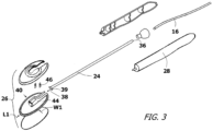
- malleable shaft 24 has a conductive core 32 that is surrounded by a dielectric insulator 34. In this manner, electricity can travel through the malleable shaft 24 from one end to the other. However, electricity cannot pass out of, or into, the malleable shaft 24 at any points other than the ends.
- the first end 36 of the malleable shaft 24 extends into the handle 28.
- the handle 28 is dielectric. Inside the confines of the handle 28, the first end 36 of the malleable shaft 24 is soldered, or otherwise electrically connected, to the second flexible terminal wire 16 that leads to the control unit 12 ( Fig. 1 ).
- the opposite second end 38 of the malleable shaft 24 connects to the paddle head 26 at the pivot joint 30.
- Two pivot nubs 39 extend from the second end 38 of the malleable shaft 24.
- the pivot nubs 39 are conductive and are coupled to the conductive core 32 of the malleable shaft 24.
- the paddle head 26 swings about the pivot nubs 39.
- the paddle head 26 can have different shapes depending upon the size of the patient and the procedure being performed. For a minimally invasive procedure, where the paddle head 26 is being inserted through a small incision, the paddle head 26 is preferably oblong in shape, such as a rectangle or an oval. As is shown, the paddle head 26 has a maximum width W1, which is preferably less than 50 millimeters. The paddle head 26 has a length L1, which is preferably about twice as long as the width W1. As such, the maximum length is preferably less than 100 millimeters. The paddle head 26 has a thin dielectric body 40. The body 40 is preferably made of a flexible but resilient material. In this manner, the width W1 of the paddle head 26 can be made momentarily smaller by being manually compressed. This helps a physician insert the paddle head 26 through small incisions and to pass the paddle head 26 between the ribs of a patient.
- the body 40 of the paddle head 26 has a curved face 42.
- the curved face 42 is either coated with, or covered by, the conductive contact surface 22.
- a connection hub 44 is disposed on the side of the body 40 opposite the conductive contact surface 22.
- the connection hub 44 forms part of the pivot joint 30 and is shaped as a yoke that receives the pivot nubs 39 at the second end 38 of the malleable shaft 24.
- At least one conductive lead 46 extends from the connection hub 44 to the conductive contact surface 22 at the opposite side of the body 40. In this manner, when the malleable shaft 24 is engaged with the connection hub 44, a reliable electrical connection exists between the conductive contact surface 22 and the conductive core 32 of the malleable shaft 24.
- any current passing through the conductive core 32 of the malleable shaft 24 can flow into the conductive contact surface 22 on the curved face surface 42 of the body 40.
- the electrical contact remains regardless of the angle of orientation achieved between the malleable shaft 24 and the paddle head 26 at the pivot joint 30.
- the paddle head 26 passes into the chest cavity through a small incision made by a physician.
- the paddle head 26 is positioned about the heart so that the paddle head 26 touches the tissue of the heart in a location selected by the physician.
- the physician shapes the malleable shaft 24 and manipulates the handle 28 in such a manner as to maximize the contact area between the conductive contact surface 22 on the paddle head 26 and the tissue of the heart.
- the defibrillation system 10 is activated. Electrical current passes through the first flexible terminal wire and into the conductive core 32 of the malleable shaft 24. The electricity continues through the malleable shaft 24 and passes into the conductive leads 46 at the pivot joint 30. The leads 46 conduct the current to the conductive contact surface 22 that is in contact with the heart tissue. The current passes into the heart so as to affect the heart. The current passes though the heart and into the body tissue between the heart and the conductive pad 14.
- the circuit is complete when the current passes out of the patient's body and into the conductive pad 14 ( Fig. 1 ), wherein the current returns to the control unit 12 ( Fig. 1 ). Since the contact area with the heart is large and the body contact with the conductive pad 14 is large, the passing current is dispersed and no burn injuries occur.
- FIG. 5 and Fig. 6 an alternate exemplary implementation of the paddle head 50 is shown.
- the paddle head 50 is disposed at the end of a malleable shaft 24.
- the malleable shaft 24 is supported by a handle (not shown.
- the handle is the same as was previously described.
- the malleable shaft 24 is also the same as was previously explained with the exception that the second end 38 of the malleable shaft 24 is now shaped to engage a ball and socket joint 52.
- the body 54 of the paddle head 50 has an upper part 56 and a lower part 58. Interposed between the upper part 56 and the lower part 58 is a conductive ball bearing 60. A bore is formed in the ball bearing 60 that receives the second end 38 of the malleable shaft 24. The ball bearing 60 contacts the conductive core 32 of the malleable shaft 24 and therefore has the same electrical potential as does the conductive core 32 of the malleable shaft 24.
- the upper part 56 and the lower part 58 of the body 40 form a socket in which the ball bearing 60 sets. As such, the ball and socket joint 52 is formed.
- the ball and socket joint 52 enables the malleable shaft 24 to move relative the paddle head 50 with more degrees of freedom than are possible with the original embodiment that was previously described.
- the ball bearing 60 rests upon a spring 62.
- the spring 62 rests upon a contact 65 that has extensions that passes through the lower part 58 of the paddle head 50 and touches the conductive contact surface 22 on the face of the paddle head 50.
- any electricity that flows into the malleable shaft 24 will pass through the conductive core 32 of the malleable shaft 24 and will pass into the ball bearing 60.
- the electricity then passes through the ball bearing 60 and into the spring 62 under the ball bearing 60.
- the spring 62 transfers the electricity to the conductive contact surface 22 on the paddle head 50.
- FIG. 7 an alternate embodiment of the paddle head 70 is shown.
- the paddle head 70 is disposed at the end of a malleable shaft 72.
- the malleable shaft 72 is supported by a handle (not shown.
- the handle is the same as was previously described.
- the malleable shaft 72 is also the same as was previously explained with the exception that the end of the malleable shaft 72 is now shaped is bent into an L-shaped engage. This produces a short lateral leg 74 at the end of the malleable shaft 72.
- the short leg 74 is used as an axle around which the paddle head 70 can pivot.
- the resulting pivot joint enables the malleable shaft 72 to move relative the paddle head 70.
- the conductive core 76 of the malleable shaft 72 is exposed and is electrically coupled to an extension 78.
- the extension 78 passes through the paddle head 70 and touches the conductive contact surface 80 on the face of the paddle head 70. In this manner, any electricity that flows into the malleable shaft 72 will pass through the conductive core 76 of the malleable shaft 73 and will pass to the conductive contact surface 80 under the paddle head 70.
Landscapes
- Health & Medical Sciences (AREA)
- Heart & Thoracic Surgery (AREA)
- Cardiology (AREA)
- Engineering & Computer Science (AREA)
- Biomedical Technology (AREA)
- Nuclear Medicine, Radiotherapy & Molecular Imaging (AREA)
- Radiology & Medical Imaging (AREA)
- Life Sciences & Earth Sciences (AREA)
- Animal Behavior & Ethology (AREA)
- General Health & Medical Sciences (AREA)
- Public Health (AREA)
- Veterinary Medicine (AREA)
- Electrotherapy Devices (AREA)
Claims (3)
- Defibrillationssystem (10), umfassend:eine Steuereinheit (12), die ein elektrisches Signal erstellt, das bei Defibrillation nützlich ist,eine leitende Auflage (14), die über einen ersten flexiblen Anschlussdraht (15) mit der Steuereinheit verbunden ist,eine Defibrillator-Paddel-Anordnung (20), die über einen zweiten flexiblen Anschlussdraht (16) an der Steuereinheit angebracht ist, die Defibrillator-Paddel-Anordnung umfassend:einen dielektrischen Handgriff (28);einen Paddelkopf (26, 50, 70), der eine leitende Oberfläche (22, 80) darauf aufweist, undeinen länglichen Schaft (24, 72) mit einem ersten Ende (36) und einem zweiten Ende (38), der den Handgriff mit dem Paddelkopf verbindet, wobei der längliche Schaft formbar ist und es ermöglicht, dass der längliche Schaft durch manuelle Manipulation in verschiedene Formen gebracht werden kann, wobei der längliche Schaft einen leitenden Kern (32) aufweist, der durch eine äußere Isolierung (34) geschützt ist, wobei der leitende Kern des formbaren Schafts im Inneren des Handgriffs freiliegt und mit dem zweiten flexiblen Anschlussdraht verlötet ist,eine Schwenkverbindung (30), die das zweite Ende des länglichen Schafts mit dem Paddelkopf verbindet, die es ermöglicht, dass der Paddelkopf manuell durch einen Bereich von verschiedenen Ausrichtungen in Bezug auf den länglichen Schaft bewegt werden kann, wobei die Schwenkverbindung eine elektrische Verbindung zwischen dem leitenden Kern des länglichen Schafts und der leitenden Oberfläche des Paddelkopfs bereitstellt; und entweder(i) ferner umfassend zwei Drehzapfennoppen (39), die sich von dem zweiten Ende des länglichen Schafts erstrecken, wobei die Drehzapfennoppen leitend sind und mit dem leitenden Kern des länglichen Schafts gekoppelt sind, wobei die Schwenkverbindung mit den Drehzapfennoppen in Eingriff sind und es der Paddelanordnung ermöglicht, über einen Bewegungsbereich um die Drehzapfennoppen zu drehen; oder(ii) wobei das Ende des formbaren Schafts in einen L-förmigen Eingriff gebogen ist, wodurch ein kurzer seitlicher Schenkel (74) an dem Ende des formbaren Schafts erzeugt wird, wobei der kurze Schenkel als eine Achse verwendet wird, um die der Paddelkopf schwenken kann, und der leitende Kern des formbaren Schafts freiliegt und elektrisch mit einer Verlängerung (78) gekoppelt ist, die durch den Paddelkopf verläuft und die leitende Kontaktfläche auf der Fläche des Paddelkopfs berührt.
- System (10) nach Anspruch 1, wobei der Paddelkopf (26) eine längliche Form mit einer Breite (W1) und einer Länge (L1) aufweist, die mindestens doppelt so lang ist wie die Breite.
- System (10) nach Anspruch 1, wobei die leitende Oberfläche (22, 80) auf dem Paddelkopf (26) gekrümmt ist.
Applications Claiming Priority (2)
| Application Number | Priority Date | Filing Date | Title |
|---|---|---|---|
| US15/230,231 US10682511B2 (en) | 2016-08-05 | 2016-08-05 | Defibrillator for minimally invasive surgical procedures |
| PCT/US2017/045380 WO2018027077A1 (en) | 2016-08-05 | 2017-08-03 | Defibrillator for minimally invasive surgical procedures |
Publications (4)
| Publication Number | Publication Date |
|---|---|
| EP3493873A1 EP3493873A1 (de) | 2019-06-12 |
| EP3493873A4 EP3493873A4 (de) | 2019-07-17 |
| EP3493873B1 true EP3493873B1 (de) | 2024-01-31 |
| EP3493873C0 EP3493873C0 (de) | 2024-01-31 |
Family
ID=61071649
Family Applications (1)
| Application Number | Title | Priority Date | Filing Date |
|---|---|---|---|
| EP17837722.2A Active EP3493873B1 (de) | 2016-08-05 | 2017-08-03 | Defibrillator für minimalinvasive chirurgische eingriffe |
Country Status (3)
| Country | Link |
|---|---|
| US (1) | US10682511B2 (de) |
| EP (1) | EP3493873B1 (de) |
| WO (1) | WO2018027077A1 (de) |
Families Citing this family (1)
| Publication number | Priority date | Publication date | Assignee | Title |
|---|---|---|---|---|
| US20240009447A1 (en) | 2022-07-09 | 2024-01-11 | USB Medical, Ltd. | Defibrillation System Having Deformable Paddle Head |
Family Cites Families (41)
| Publication number | Priority date | Publication date | Assignee | Title |
|---|---|---|---|---|
| US2985172A (en) * | 1959-08-31 | 1961-05-23 | William C Jones | Tissue contact electrode |
| US3389703A (en) * | 1966-02-03 | 1968-06-25 | Zenith Radio Corp | Defibrillator electrode or the like |
| US3670736A (en) | 1970-07-17 | 1972-06-20 | Health Systems Inc | Therapeutic instrumentation electrode |
| US4852585A (en) | 1980-08-08 | 1989-08-01 | Darox Corporation | Tin-stannous chloride electrode element |
| US4554910A (en) | 1983-02-28 | 1985-11-26 | Health Education Publication Company, Inc. | Cardio pulmonary resuscitation pressure indicator |
| US4681112A (en) | 1985-01-08 | 1987-07-21 | Physio-Control Corporation | Medical instrument including electrodes adapted for right and left-handed use |
| US4705044A (en) | 1985-11-12 | 1987-11-10 | Kone Instruments Inc. | Defibrillator paddle |
| JPH01259872A (ja) | 1988-04-11 | 1989-10-17 | Fukuda Denshi Co Ltd | 除細動器用電極 |
| US5645522A (en) | 1991-04-17 | 1997-07-08 | The Regents Of The University Of California | Devices and methods for controlled external chest compression |
| US7445594B1 (en) | 1995-09-20 | 2008-11-04 | Medtronic, Inc. | Method and apparatus for temporarily immobilizing a local area of tissue |
| US5904711A (en) | 1996-02-08 | 1999-05-18 | Heartport, Inc. | Expandable thoracoscopic defibrillation catheter system and method |
| US5978714A (en) | 1997-06-06 | 1999-11-02 | Zadini; Filiberto | Epicardial percutaneous device for electrical cardiac therapy |
| US6156060A (en) * | 1998-07-31 | 2000-12-05 | Surx, Inc. | Static devices and methods to shrink tissues for incontinence |
| US6360125B1 (en) | 1998-12-21 | 2002-03-19 | Institute Of Critical Care Medicine | CPR protector |
| US6097987A (en) | 1998-12-30 | 2000-08-01 | Medical Research Laboratories, Inc. | External defibrillator electrode apparatus |
| US6872080B2 (en) | 1999-01-29 | 2005-03-29 | Cardiac Science, Inc. | Programmable AED-CPR training device |
| US7120495B2 (en) | 2000-09-18 | 2006-10-10 | Cameron Health, Inc. | Flexible subcutaneous implantable cardioverter-defibrillator |
| US7069080B2 (en) | 2000-09-18 | 2006-06-27 | Cameron Health, Inc. | Active housing and subcutaneous electrode cardioversion/defibrillating system |
| US6721597B1 (en) | 2000-09-18 | 2004-04-13 | Cameron Health, Inc. | Subcutaneous only implantable cardioverter defibrillator and optional pacer |
| US6988003B2 (en) | 2000-09-18 | 2006-01-17 | Cameron Health, Inc. | Implantable cardioverter-defibrillator having two spaced apart shocking electrodes on housing |
| US20020035381A1 (en) | 2000-09-18 | 2002-03-21 | Cameron Health, Inc. | Subcutaneous electrode with improved contact shape for transthoracic conduction |
| US6950705B2 (en) | 2000-09-18 | 2005-09-27 | Cameron Health, Inc. | Canister designs for implantable cardioverter-defibrillators |
| US7043299B2 (en) | 2000-09-18 | 2006-05-09 | Cameron Health, Inc. | Subcutaneous implantable cardioverter-defibrillator employing a telescoping lead |
| US7146225B2 (en) | 2002-10-30 | 2006-12-05 | Medtronic, Inc. | Methods and apparatus for accessing and stabilizing an area of the heart |
| US20020198583A1 (en) | 2001-06-22 | 2002-12-26 | Joseph Rock | Disposable sheath providing cardiac stimulation and method |
| US6714817B2 (en) | 2001-08-31 | 2004-03-30 | Medtronic Physio-Control Manufacturing Corp. | Hard paddle for an external defibrillator |
| US6782293B2 (en) | 2001-09-14 | 2004-08-24 | Zoll Medical Corporation | Defibrillation electrode assembly including CPR pad |
| US7016727B2 (en) | 2001-11-05 | 2006-03-21 | Koninklijke Philips Electronics N.V. | Cartridge having a power source and electrode pad for defibrillator having a rechargeable battery |
| US7120503B2 (en) | 2002-04-08 | 2006-10-10 | Koninklijke Philips Electronics, N.V. | Sterile disposable internal defibrillation paddles |
| US7321794B2 (en) | 2002-11-15 | 2008-01-22 | Advanced Bionics Corporation | Method and system for treating atrial fibrillation |
| JP4385245B2 (ja) | 2002-12-06 | 2009-12-16 | 日本光電工業株式会社 | 除細動器 |
| US20040186545A1 (en) | 2003-03-20 | 2004-09-23 | Rosero Spencer Z. | Temporary percutaneous cardioverter-defibrillator |
| US7162309B2 (en) | 2003-04-07 | 2007-01-09 | Medtronic, Inc. | Epicardial lead delivery system and method |
| US7769465B2 (en) | 2003-06-11 | 2010-08-03 | Matos Jeffrey A | System for cardiac resuscitation |
| US6961611B2 (en) | 2003-06-27 | 2005-11-01 | Zoll Medical Corporation | Multi-configuration defibrillation connector |
| WO2006102420A2 (en) | 2005-03-21 | 2006-09-28 | Defibtech, Llc | Pcb blade connector system and method |
| US8452393B1 (en) * | 2005-11-07 | 2013-05-28 | Stephen T. Epstein | Defibrillation paddle structure and its associated method of use |
| US8099163B2 (en) | 2006-04-04 | 2012-01-17 | The Invention Science Fund I, Llc | Automated defibrillator |
| US8024037B2 (en) | 2006-08-01 | 2011-09-20 | Kumar Uday N | External defibrillator |
| JP5046056B2 (ja) | 2009-07-13 | 2012-10-10 | 日本光電工業株式会社 | 内用パドル |
| DE102011111649A1 (de) | 2011-08-26 | 2013-02-28 | Peter Osypka | Implantierbare Epikardiale Elektroden Anordnung |
-
2016
- 2016-08-05 US US15/230,231 patent/US10682511B2/en active Active
-
2017
- 2017-08-03 WO PCT/US2017/045380 patent/WO2018027077A1/en not_active Ceased
- 2017-08-03 EP EP17837722.2A patent/EP3493873B1/de active Active
Also Published As
| Publication number | Publication date |
|---|---|
| WO2018027077A1 (en) | 2018-02-08 |
| US20180036528A1 (en) | 2018-02-08 |
| EP3493873A1 (de) | 2019-06-12 |
| US10682511B2 (en) | 2020-06-16 |
| EP3493873C0 (de) | 2024-01-31 |
| EP3493873A4 (de) | 2019-07-17 |
Similar Documents
| Publication | Publication Date | Title |
|---|---|---|
| US5797923A (en) | Electrode delivery instrument | |
| US5042463A (en) | Patch electrode for heart defibrillator | |
| TW561061B (en) | Electro-acupuncture device with d-shaped stimulation electrodes | |
| US20070060966A1 (en) | Method of treating cardiac arrhythmias | |
| WO2000074769A9 (en) | Cardiac shock electrode system and corresponding implantable defibrillator system | |
| WO2006105395A3 (en) | Trans-septal/trans-myocardial ventricular pacing lead | |
| CA2326155A1 (en) | Improved rf bipolar end effector for use in electrosurgical instruments | |
| US20100179410A1 (en) | Single and multi-needle electromyographic (emg) recording electrode configurations for intraoperative nerve integrity montoring | |
| US20220266024A1 (en) | Neurostimulation device with recording patch | |
| US20240009447A1 (en) | Defibrillation System Having Deformable Paddle Head | |
| US10682511B2 (en) | Defibrillator for minimally invasive surgical procedures | |
| US6546293B2 (en) | Hook-shaped spinal cord electrode assembly having a telescoping electrode | |
| CN206424426U (zh) | 治疗仪电极片 | |
| US11260224B2 (en) | Deep tissue pulsed electromagnetic field therapy apparatus and method of use thereof | |
| US20160081734A1 (en) | Bipolar forceps | |
| JP4103101B2 (ja) | 除細動用電極および除細動システム | |
| EP1948305B1 (de) | Defibrillations-paddelstruktur | |
| JPS62322A (ja) | 経穴用電極 | |
| US20060282124A1 (en) | Apparatus and method for cardioversion | |
| RU207638U1 (ru) | Адаптивное электродное устройство | |
| CN216676713U (zh) | 可更换耳道电极的耳迷走神经刺激仪 | |
| CN211798252U (zh) | 一种高频电流治疗系统用电极 | |
| CN206454119U (zh) | 一种带起搏除颤功能的导线 | |
| JPH0733799Y2 (ja) | 皮接治療具 | |
| JPH0626246Y2 (ja) | バイポーラ凝固器用電極 |
Legal Events
| Date | Code | Title | Description |
|---|---|---|---|
| STAA | Information on the status of an ep patent application or granted ep patent |
Free format text: STATUS: THE INTERNATIONAL PUBLICATION HAS BEEN MADE |
|
| PUAI | Public reference made under article 153(3) epc to a published international application that has entered the european phase |
Free format text: ORIGINAL CODE: 0009012 |
|
| STAA | Information on the status of an ep patent application or granted ep patent |
Free format text: STATUS: REQUEST FOR EXAMINATION WAS MADE |
|
| 17P | Request for examination filed |
Effective date: 20190305 |
|
| AK | Designated contracting states |
Kind code of ref document: A1 Designated state(s): AL AT BE BG CH CY CZ DE DK EE ES FI FR GB GR HR HU IE IS IT LI LT LU LV MC MK MT NL NO PL PT RO RS SE SI SK SM TR |
|
| AX | Request for extension of the european patent |
Extension state: BA ME |
|
| A4 | Supplementary search report drawn up and despatched |
Effective date: 20190619 |
|
| RIC1 | Information provided on ipc code assigned before grant |
Ipc: A61N 1/00 20060101AFI20190613BHEP Ipc: A61N 1/18 20060101ALI20190613BHEP Ipc: A61N 1/05 20060101ALI20190613BHEP Ipc: A61N 1/04 20060101ALI20190613BHEP Ipc: A61N 1/26 20060101ALI20190613BHEP Ipc: A61N 1/06 20060101ALI20190613BHEP Ipc: A61N 1/08 20060101ALI20190613BHEP |
|
| DAV | Request for validation of the european patent (deleted) | ||
| DAX | Request for extension of the european patent (deleted) | ||
| STAA | Information on the status of an ep patent application or granted ep patent |
Free format text: STATUS: EXAMINATION IS IN PROGRESS |
|
| 17Q | First examination report despatched |
Effective date: 20220720 |
|
| REG | Reference to a national code |
Ref country code: DE Ref legal event code: R079 Free format text: PREVIOUS MAIN CLASS: A61N0001000000 Ipc: A61N0001050000 Ref country code: DE Ref legal event code: R079 Ref document number: 602017078896 Country of ref document: DE Free format text: PREVIOUS MAIN CLASS: A61N0001000000 Ipc: A61N0001050000 |
|
| RIC1 | Information provided on ipc code assigned before grant |
Ipc: A61N 1/39 20060101ALI20230526BHEP Ipc: A61N 1/05 20060101AFI20230526BHEP |
|
| GRAP | Despatch of communication of intention to grant a patent |
Free format text: ORIGINAL CODE: EPIDOSNIGR1 |
|
| STAA | Information on the status of an ep patent application or granted ep patent |
Free format text: STATUS: GRANT OF PATENT IS INTENDED |
|
| INTG | Intention to grant announced |
Effective date: 20230901 |
|
| GRAS | Grant fee paid |
Free format text: ORIGINAL CODE: EPIDOSNIGR3 |
|
| GRAA | (expected) grant |
Free format text: ORIGINAL CODE: 0009210 |
|
| STAA | Information on the status of an ep patent application or granted ep patent |
Free format text: STATUS: THE PATENT HAS BEEN GRANTED |
|
| AK | Designated contracting states |
Kind code of ref document: B1 Designated state(s): AL AT BE BG CH CY CZ DE DK EE ES FI FR GB GR HR HU IE IS IT LI LT LU LV MC MK MT NL NO PL PT RO RS SE SI SK SM TR |
|
| REG | Reference to a national code |
Ref country code: GB Ref legal event code: FG4D Ref country code: CH Ref legal event code: EP |
|
| REG | Reference to a national code |
Ref country code: DE Ref legal event code: R096 Ref document number: 602017078896 Country of ref document: DE |
|
| REG | Reference to a national code |
Ref country code: IE Ref legal event code: FG4D |
|
| U01 | Request for unitary effect filed |
Effective date: 20240221 |
|
| U07 | Unitary effect registered |
Designated state(s): AT BE BG DE DK EE FI FR IT LT LU LV MT NL PT SE SI Effective date: 20240229 |
|
| REG | Reference to a national code |
Ref country code: LT Ref legal event code: MG9D |
|
| PG25 | Lapsed in a contracting state [announced via postgrant information from national office to epo] |
Ref country code: IS Free format text: LAPSE BECAUSE OF FAILURE TO SUBMIT A TRANSLATION OF THE DESCRIPTION OR TO PAY THE FEE WITHIN THE PRESCRIBED TIME-LIMIT Effective date: 20240531 |
|
| PG25 | Lapsed in a contracting state [announced via postgrant information from national office to epo] |
Ref country code: GR Free format text: LAPSE BECAUSE OF FAILURE TO SUBMIT A TRANSLATION OF THE DESCRIPTION OR TO PAY THE FEE WITHIN THE PRESCRIBED TIME-LIMIT Effective date: 20240501 |
|
| PG25 | Lapsed in a contracting state [announced via postgrant information from national office to epo] |
Ref country code: RS Free format text: LAPSE BECAUSE OF FAILURE TO SUBMIT A TRANSLATION OF THE DESCRIPTION OR TO PAY THE FEE WITHIN THE PRESCRIBED TIME-LIMIT Effective date: 20240430 Ref country code: HR Free format text: LAPSE BECAUSE OF FAILURE TO SUBMIT A TRANSLATION OF THE DESCRIPTION OR TO PAY THE FEE WITHIN THE PRESCRIBED TIME-LIMIT Effective date: 20240131 |
|
| PG25 | Lapsed in a contracting state [announced via postgrant information from national office to epo] |
Ref country code: ES Free format text: LAPSE BECAUSE OF FAILURE TO SUBMIT A TRANSLATION OF THE DESCRIPTION OR TO PAY THE FEE WITHIN THE PRESCRIBED TIME-LIMIT Effective date: 20240131 |
|
| PG25 | Lapsed in a contracting state [announced via postgrant information from national office to epo] |
Ref country code: RS Free format text: LAPSE BECAUSE OF FAILURE TO SUBMIT A TRANSLATION OF THE DESCRIPTION OR TO PAY THE FEE WITHIN THE PRESCRIBED TIME-LIMIT Effective date: 20240430 Ref country code: NO Free format text: LAPSE BECAUSE OF FAILURE TO SUBMIT A TRANSLATION OF THE DESCRIPTION OR TO PAY THE FEE WITHIN THE PRESCRIBED TIME-LIMIT Effective date: 20240430 Ref country code: IS Free format text: LAPSE BECAUSE OF FAILURE TO SUBMIT A TRANSLATION OF THE DESCRIPTION OR TO PAY THE FEE WITHIN THE PRESCRIBED TIME-LIMIT Effective date: 20240531 Ref country code: HR Free format text: LAPSE BECAUSE OF FAILURE TO SUBMIT A TRANSLATION OF THE DESCRIPTION OR TO PAY THE FEE WITHIN THE PRESCRIBED TIME-LIMIT Effective date: 20240131 Ref country code: GR Free format text: LAPSE BECAUSE OF FAILURE TO SUBMIT A TRANSLATION OF THE DESCRIPTION OR TO PAY THE FEE WITHIN THE PRESCRIBED TIME-LIMIT Effective date: 20240501 Ref country code: ES Free format text: LAPSE BECAUSE OF FAILURE TO SUBMIT A TRANSLATION OF THE DESCRIPTION OR TO PAY THE FEE WITHIN THE PRESCRIBED TIME-LIMIT Effective date: 20240131 |
|
| PG25 | Lapsed in a contracting state [announced via postgrant information from national office to epo] |
Ref country code: PL Free format text: LAPSE BECAUSE OF FAILURE TO SUBMIT A TRANSLATION OF THE DESCRIPTION OR TO PAY THE FEE WITHIN THE PRESCRIBED TIME-LIMIT Effective date: 20240131 |
|
| PG25 | Lapsed in a contracting state [announced via postgrant information from national office to epo] |
Ref country code: PL Free format text: LAPSE BECAUSE OF FAILURE TO SUBMIT A TRANSLATION OF THE DESCRIPTION OR TO PAY THE FEE WITHIN THE PRESCRIBED TIME-LIMIT Effective date: 20240131 |
|
| U20 | Renewal fee for the european patent with unitary effect paid |
Year of fee payment: 8 Effective date: 20240828 |
|
| PG25 | Lapsed in a contracting state [announced via postgrant information from national office to epo] |
Ref country code: SM Free format text: LAPSE BECAUSE OF FAILURE TO SUBMIT A TRANSLATION OF THE DESCRIPTION OR TO PAY THE FEE WITHIN THE PRESCRIBED TIME-LIMIT Effective date: 20240131 |
|
| PG25 | Lapsed in a contracting state [announced via postgrant information from national office to epo] |
Ref country code: CZ Free format text: LAPSE BECAUSE OF FAILURE TO SUBMIT A TRANSLATION OF THE DESCRIPTION OR TO PAY THE FEE WITHIN THE PRESCRIBED TIME-LIMIT Effective date: 20240131 |
|
| PG25 | Lapsed in a contracting state [announced via postgrant information from national office to epo] |
Ref country code: SK Free format text: LAPSE BECAUSE OF FAILURE TO SUBMIT A TRANSLATION OF THE DESCRIPTION OR TO PAY THE FEE WITHIN THE PRESCRIBED TIME-LIMIT Effective date: 20240131 |
|
| PG25 | Lapsed in a contracting state [announced via postgrant information from national office to epo] |
Ref country code: SM Free format text: LAPSE BECAUSE OF FAILURE TO SUBMIT A TRANSLATION OF THE DESCRIPTION OR TO PAY THE FEE WITHIN THE PRESCRIBED TIME-LIMIT Effective date: 20240131 Ref country code: SK Free format text: LAPSE BECAUSE OF FAILURE TO SUBMIT A TRANSLATION OF THE DESCRIPTION OR TO PAY THE FEE WITHIN THE PRESCRIBED TIME-LIMIT Effective date: 20240131 Ref country code: RO Free format text: LAPSE BECAUSE OF FAILURE TO SUBMIT A TRANSLATION OF THE DESCRIPTION OR TO PAY THE FEE WITHIN THE PRESCRIBED TIME-LIMIT Effective date: 20240131 Ref country code: CZ Free format text: LAPSE BECAUSE OF FAILURE TO SUBMIT A TRANSLATION OF THE DESCRIPTION OR TO PAY THE FEE WITHIN THE PRESCRIBED TIME-LIMIT Effective date: 20240131 |
|
| REG | Reference to a national code |
Ref country code: DE Ref legal event code: R097 Ref document number: 602017078896 Country of ref document: DE |
|
| PLBE | No opposition filed within time limit |
Free format text: ORIGINAL CODE: 0009261 |
|
| STAA | Information on the status of an ep patent application or granted ep patent |
Free format text: STATUS: NO OPPOSITION FILED WITHIN TIME LIMIT |
|
| 26N | No opposition filed |
Effective date: 20241101 |
|
| REG | Reference to a national code |
Ref country code: CH Ref legal event code: PL |
|
| PG25 | Lapsed in a contracting state [announced via postgrant information from national office to epo] |
Ref country code: CH Free format text: LAPSE BECAUSE OF NON-PAYMENT OF DUE FEES Effective date: 20240831 Ref country code: MC Free format text: LAPSE BECAUSE OF FAILURE TO SUBMIT A TRANSLATION OF THE DESCRIPTION OR TO PAY THE FEE WITHIN THE PRESCRIBED TIME-LIMIT Effective date: 20240131 |
|
| PG25 | Lapsed in a contracting state [announced via postgrant information from national office to epo] |
Ref country code: IE Free format text: LAPSE BECAUSE OF NON-PAYMENT OF DUE FEES Effective date: 20240803 |
|
| U20 | Renewal fee for the european patent with unitary effect paid |
Year of fee payment: 9 Effective date: 20250709 |
|
| PGFP | Annual fee paid to national office [announced via postgrant information from national office to epo] |
Ref country code: GB Payment date: 20250709 Year of fee payment: 9 |
|
| PG25 | Lapsed in a contracting state [announced via postgrant information from national office to epo] |
Ref country code: CY Free format text: LAPSE BECAUSE OF FAILURE TO SUBMIT A TRANSLATION OF THE DESCRIPTION OR TO PAY THE FEE WITHIN THE PRESCRIBED TIME-LIMIT; INVALID AB INITIO Effective date: 20170803 |
|
| PG25 | Lapsed in a contracting state [announced via postgrant information from national office to epo] |
Ref country code: HU Free format text: LAPSE BECAUSE OF FAILURE TO SUBMIT A TRANSLATION OF THE DESCRIPTION OR TO PAY THE FEE WITHIN THE PRESCRIBED TIME-LIMIT; INVALID AB INITIO Effective date: 20170803 |