EP3492960B1 - Lentille de collimation arquée formant un éclairage semblables à un disque - Google Patents
Lentille de collimation arquée formant un éclairage semblables à un disque Download PDFInfo
- Publication number
- EP3492960B1 EP3492960B1 EP18209028.2A EP18209028A EP3492960B1 EP 3492960 B1 EP3492960 B1 EP 3492960B1 EP 18209028 A EP18209028 A EP 18209028A EP 3492960 B1 EP3492960 B1 EP 3492960B1
- Authority
- EP
- European Patent Office
- Prior art keywords
- lens
- arched
- light
- arched lens
- illumination
- Prior art date
- Legal status (The legal status is an assumption and is not a legal conclusion. Google has not performed a legal analysis and makes no representation as to the accuracy of the status listed.)
- Active
Links
- 238000005286 illumination Methods 0.000 title claims description 55
- 230000003287 optical effect Effects 0.000 claims description 35
- 239000000758 substrate Substances 0.000 claims description 9
- 239000000463 material Substances 0.000 claims description 5
- 238000004519 manufacturing process Methods 0.000 claims description 2
- 239000003292 glue Substances 0.000 claims 1
- 238000000034 method Methods 0.000 description 16
- 238000003384 imaging method Methods 0.000 description 15
- 238000010586 diagram Methods 0.000 description 9
- 238000003491 array Methods 0.000 description 7
- 230000005540 biological transmission Effects 0.000 description 7
- 230000005855 radiation Effects 0.000 description 6
- 238000000701 chemical imaging Methods 0.000 description 4
- 239000011295 pitch Substances 0.000 description 4
- 230000015572 biosynthetic process Effects 0.000 description 3
- 238000005755 formation reaction Methods 0.000 description 3
- 230000017525 heat dissipation Effects 0.000 description 3
- 238000012545 processing Methods 0.000 description 3
- 239000007787 solid Substances 0.000 description 3
- 230000004075 alteration Effects 0.000 description 2
- 238000013461 design Methods 0.000 description 2
- 230000000694 effects Effects 0.000 description 2
- -1 poly(methyl methacrylate) Polymers 0.000 description 2
- 229920003229 poly(methyl methacrylate) Polymers 0.000 description 2
- 239000004926 polymethyl methacrylate Substances 0.000 description 2
- 230000003595 spectral effect Effects 0.000 description 2
- 229930091051 Arenine Natural products 0.000 description 1
- 206010010071 Coma Diseases 0.000 description 1
- 238000010521 absorption reaction Methods 0.000 description 1
- 230000006978 adaptation Effects 0.000 description 1
- 238000013459 approach Methods 0.000 description 1
- 238000010276 construction Methods 0.000 description 1
- 230000006735 deficit Effects 0.000 description 1
- 230000001419 dependent effect Effects 0.000 description 1
- 239000002019 doping agent Substances 0.000 description 1
- 239000000839 emulsion Substances 0.000 description 1
- 239000010408 film Substances 0.000 description 1
- 239000011521 glass Substances 0.000 description 1
- 238000001093 holography Methods 0.000 description 1
- 230000003993 interaction Effects 0.000 description 1
- 230000001788 irregular Effects 0.000 description 1
- 238000005259 measurement Methods 0.000 description 1
- 229910052751 metal Inorganic materials 0.000 description 1
- 239000002184 metal Substances 0.000 description 1
- 229910044991 metal oxide Inorganic materials 0.000 description 1
- 150000004706 metal oxides Chemical class 0.000 description 1
- 150000002739 metals Chemical class 0.000 description 1
- 230000004048 modification Effects 0.000 description 1
- 238000012986 modification Methods 0.000 description 1
- 238000012544 monitoring process Methods 0.000 description 1
- 239000004417 polycarbonate Substances 0.000 description 1
- 229920000515 polycarbonate Polymers 0.000 description 1
- 229920000642 polymer Polymers 0.000 description 1
- 230000001902 propagating effect Effects 0.000 description 1
- 238000009877 rendering Methods 0.000 description 1
- 239000004065 semiconductor Substances 0.000 description 1
- 239000010409 thin film Substances 0.000 description 1
- 238000012876 topography Methods 0.000 description 1
Images


Classifications
-
- G—PHYSICS
- G02—OPTICS
- G02B—OPTICAL ELEMENTS, SYSTEMS OR APPARATUS
- G02B3/00—Simple or compound lenses
- G02B3/02—Simple or compound lenses with non-spherical faces
- G02B3/08—Simple or compound lenses with non-spherical faces with discontinuous faces, e.g. Fresnel lens
-
- F—MECHANICAL ENGINEERING; LIGHTING; HEATING; WEAPONS; BLASTING
- F21—LIGHTING
- F21V—FUNCTIONAL FEATURES OR DETAILS OF LIGHTING DEVICES OR SYSTEMS THEREOF; STRUCTURAL COMBINATIONS OF LIGHTING DEVICES WITH OTHER ARTICLES, NOT OTHERWISE PROVIDED FOR
- F21V5/00—Refractors for light sources
- F21V5/04—Refractors for light sources of lens shape
- F21V5/045—Refractors for light sources of lens shape the lens having discontinuous faces, e.g. Fresnel lenses
-
- F—MECHANICAL ENGINEERING; LIGHTING; HEATING; WEAPONS; BLASTING
- F21—LIGHTING
- F21V—FUNCTIONAL FEATURES OR DETAILS OF LIGHTING DEVICES OR SYSTEMS THEREOF; STRUCTURAL COMBINATIONS OF LIGHTING DEVICES WITH OTHER ARTICLES, NOT OTHERWISE PROVIDED FOR
- F21V5/00—Refractors for light sources
- F21V5/04—Refractors for light sources of lens shape
- F21V5/046—Refractors for light sources of lens shape the lens having a rotationally symmetrical shape about an axis for transmitting light in a direction mainly perpendicular to this axis, e.g. ring or annular lens with light source disposed inside the ring
-
- G—PHYSICS
- G01—MEASURING; TESTING
- G01S—RADIO DIRECTION-FINDING; RADIO NAVIGATION; DETERMINING DISTANCE OR VELOCITY BY USE OF RADIO WAVES; LOCATING OR PRESENCE-DETECTING BY USE OF THE REFLECTION OR RERADIATION OF RADIO WAVES; ANALOGOUS ARRANGEMENTS USING OTHER WAVES
- G01S7/00—Details of systems according to groups G01S13/00, G01S15/00, G01S17/00
- G01S7/48—Details of systems according to groups G01S13/00, G01S15/00, G01S17/00 of systems according to group G01S17/00
- G01S7/481—Constructional features, e.g. arrangements of optical elements
- G01S7/4814—Constructional features, e.g. arrangements of optical elements of transmitters alone
-
- G—PHYSICS
- G02—OPTICS
- G02B—OPTICAL ELEMENTS, SYSTEMS OR APPARATUS
- G02B19/00—Condensers, e.g. light collectors or similar non-imaging optics
- G02B19/0004—Condensers, e.g. light collectors or similar non-imaging optics characterised by the optical means employed
- G02B19/0028—Condensers, e.g. light collectors or similar non-imaging optics characterised by the optical means employed refractive and reflective surfaces, e.g. non-imaging catadioptric systems
-
- G—PHYSICS
- G02—OPTICS
- G02B—OPTICAL ELEMENTS, SYSTEMS OR APPARATUS
- G02B19/00—Condensers, e.g. light collectors or similar non-imaging optics
- G02B19/0033—Condensers, e.g. light collectors or similar non-imaging optics characterised by the use
- G02B19/0047—Condensers, e.g. light collectors or similar non-imaging optics characterised by the use for use with a light source
- G02B19/0052—Condensers, e.g. light collectors or similar non-imaging optics characterised by the use for use with a light source the light source comprising a laser diode
-
- G—PHYSICS
- G02—OPTICS
- G02B—OPTICAL ELEMENTS, SYSTEMS OR APPARATUS
- G02B26/00—Optical devices or arrangements for the control of light using movable or deformable optical elements
- G02B26/08—Optical devices or arrangements for the control of light using movable or deformable optical elements for controlling the direction of light
- G02B26/10—Scanning systems
-
- G—PHYSICS
- G02—OPTICS
- G02B—OPTICAL ELEMENTS, SYSTEMS OR APPARATUS
- G02B3/00—Simple or compound lenses
- G02B3/0087—Simple or compound lenses with index gradient
-
- G—PHYSICS
- G02—OPTICS
- G02B—OPTICAL ELEMENTS, SYSTEMS OR APPARATUS
- G02B3/00—Simple or compound lenses
- G02B3/02—Simple or compound lenses with non-spherical faces
- G02B3/06—Simple or compound lenses with non-spherical faces with cylindrical or toric faces
-
- G—PHYSICS
- G02—OPTICS
- G02B—OPTICAL ELEMENTS, SYSTEMS OR APPARATUS
- G02B5/00—Optical elements other than lenses
- G02B5/32—Holograms used as optical elements
-
- G—PHYSICS
- G01—MEASURING; TESTING
- G01S—RADIO DIRECTION-FINDING; RADIO NAVIGATION; DETERMINING DISTANCE OR VELOCITY BY USE OF RADIO WAVES; LOCATING OR PRESENCE-DETECTING BY USE OF THE REFLECTION OR RERADIATION OF RADIO WAVES; ANALOGOUS ARRANGEMENTS USING OTHER WAVES
- G01S17/00—Systems using the reflection or reradiation of electromagnetic waves other than radio waves, e.g. lidar systems
- G01S17/02—Systems using the reflection of electromagnetic waves other than radio waves
- G01S17/06—Systems determining position data of a target
- G01S17/42—Simultaneous measurement of distance and other co-ordinates
-
- G—PHYSICS
- G01—MEASURING; TESTING
- G01S—RADIO DIRECTION-FINDING; RADIO NAVIGATION; DETERMINING DISTANCE OR VELOCITY BY USE OF RADIO WAVES; LOCATING OR PRESENCE-DETECTING BY USE OF THE REFLECTION OR RERADIATION OF RADIO WAVES; ANALOGOUS ARRANGEMENTS USING OTHER WAVES
- G01S17/00—Systems using the reflection or reradiation of electromagnetic waves other than radio waves, e.g. lidar systems
- G01S17/88—Lidar systems specially adapted for specific applications
- G01S17/89—Lidar systems specially adapted for specific applications for mapping or imaging
-
- G—PHYSICS
- G02—OPTICS
- G02B—OPTICAL ELEMENTS, SYSTEMS OR APPARATUS
- G02B27/00—Optical systems or apparatus not provided for by any of the groups G02B1/00 - G02B26/00, G02B30/00
- G02B27/30—Collimators
Definitions
- the subject matter disclosed herein relates generally to illumination lenses.
- EP 3,144,586 A2 relates to a modular illumination system capable of producing a light beam having a wide field of view - e.g., in excess of ninety degrees - while maintaining a high collection efficiency as well as a high degree of beam homogeneity.
- the illumination system comprises an elementary unit having a linear array of light sources. Light from the light sources is collimated using a corresponding array of catadioptric lenses, and the collimated light is homogenised in the tangential plane using two cylindrical lens arrays set in tandem to one another. The homogenised light is then collimated in the sagittal plane using a cylindrical lens that is set perpendicular to the lenses of the two cylindrical lens arrays to yield a wide linear beam.
- the linear array of light sources can be replaced with a two-dimensional array, and the cylindrical lenses can be replaced with spherical lenses.
- US 6,631,016 B1 relates to full-parallax holographic stereograms on curved substrates, comprising the recording of full parallax, one-step, full color holographic stereograms so as to properly display the resultant imagery when the hologram is mounted on a curved substrate after recording. It also comprises mounting the hologram on a substrate that can be curved in one or two dimensions, thereby producing any arbitrary shape.
- the hologram is scalable, making it possible to create curved holograms of unlimited size.
- the hologram can be generated for application to one of a variety of curved substrates, including hemi-cylindrical substrates with opaque backing to allow up to 180 degrees of horizontal view zone, and full cylinders with transparent backing to allow viewing through 360 degrees horizontally. It also includes adaptation to conical, spherical, and other curved geometric and irregular topographies.
- CN 203 892 962 U relates to a medium-and-small-diameter high-luminous-intensity LED annular-irradiation signal lamp which comprises a multi-surface cylindrical heat dissipation body, an annular parabolic reflector component arranged on the periphery of the multi-surface cylindrical heat dissipation body, and an annular convex lens arranged in the annular space defined by the reflection surface of the annular parabolic reflector component, wherein an LED luminous unit is fixed to each outer plane of the multi-surface cylindrical heat dissipation body, the annular parabolic reflector component is formed by multiple straight-strip-shaped parabolic reflector units, light scattered by each LED luminous unit is reflected by the reflection surface of the corresponding straight-strip-shaped parabolic reflector unit, and light scattered by the LED luminous units and light reflected by the annular parabolic reflector component are converged in the vertical direction and then diffused in the horizontal direction in an annular mode by the annular con
- the medium-and-small-diameter high-luminous-intensity LED annular-irradiation signal lamp solves the problem that there is still part of light not effectively utilized for existing annular-irradiation lamps, and the light utilization rate is higher than that of the existing annular-irradiation lamps under the condition of the same power.
- the term "or” is intended to mean an inclusive “or” rather than an exclusive “or.” That is, unless specified otherwise, or clear from the context, the phrase “X employs A or B” is intended to mean any of the natural inclusive permutations. That is, the phrase “X employs A or B” is satisfied by any of the following instances: X employs A; X employs B; or X employs both A and B.
- the articles “a” and “an” as used in this application and the appended claims should generally be construed to mean “one or more” unless specified otherwise or clear from the context to be directed to a singular form.
- a “set” in the subject disclosure includes one or more elements or entities.
- a set of controllers includes one or more controllers; a set of data resources includes one or more data resources; etc.
- group refers to a collection of one or more entities; e.g., a group of nodes refers to one or more nodes.
- VCSEL Vertical Cavity Surface Emitting Laser
- FIG. 1 is a diagram illustrating capture of an image by an example, non-limiting illumination and imaging system 100, which comprises an illuminator 102 and an imaging system 118.
- Illuminator 102 emits light 104 into a viewing area to be imaged. Portions of the emitted light that are incident on solid objects and surfaces within the field of view - such as solid bodies 108, 110, and 112 and wall 106 - are scattered by the illuminated objects and surfaces as scattered rays 114.
- Subsets of the scattered rays 116 are received and collected by the imaging system 118, and image capturing components within the imaging system 118 (e.g., a photodiode array, a charged-coupled device, a complimentary metal-oxide semiconductor, photographic film or emulsion, etc.) record the rays 116 reflected from the objects and surfaces as an image (or as a set of point cloud data in the case of three-dimensional imaging systems).
- image capturing components within the imaging system 118 e.g., a photodiode array, a charged-coupled device, a complimentary metal-oxide semiconductor, photographic film or emulsion, etc.
- Illuminator 102 and imaging system 118 can be, for example, components of a commercial camera or a more specialized camera such as a multi-spectral or hyper-spectral imaging camera.
- Imaging system 100 may also be components of a time-of-flight (TOF) camera (also known as a three-dimensional image sensor) capable of generating distance information for points within the viewing field.
- TOF time-of-flight
- Illumination systems are typically designed to suit the requirements of a particular type of camera or imaging system. For example, commercial cameras are equipped with a relatively simple flash illuminator to compensate for a deficit of ambient light under dark conditions. Multi-spectral and hyper-spectral imaging systems employ more specialized cameras designed to capture image information at specific electromagnetic frequencies, and therefore use illumination systems that generate light customized for the specific spectral ranges required. With the advent of solid-state illumination sources, such as lasers, VCSELs, and light-emitting diodes (LEDs), which are capable of emitting light at narrow spectral bands, illumination systems are capable of illuminating a viewing space with light directed to specific defined wavelengths while minimizing the effects of background radiation with compatible band-pass filters.
- solid-state illumination sources such as lasers, VCSELs, and light-emitting diodes (LEDs)
- imaging in the three-dimensional space requires the collection of many photo-electrons to accurately render the depth of an object, which can place great demands on the illumination system.
- These requirements call for an illumination system capable of forming an illumination field that overlaps the field-of-view of the imaging system effectively and prudently.
- FIG. 2 is a diagram of an example illumination system 202.
- a given illumination system 202 can comprise a light source 204 - e.g., an LED, a laser (e.g., a vertical-cavity surface-emitting laser, or VCSEL), or other type of source - that generates and emits light 208, and optical components 206 that collect, collimate, and direct the light from the source 204 to the viewing field as a processed beam 210.
- the delivery efficiency of a given illumination system - that is, the percentage of light generated by the source 204 that is ultimately delivered to the viewing field - can be described as the product of the collection efficiency and the transmission efficiency of the system.
- the collection efficiency describes the percentage of light 208 emitted by the source 204 that is collected by the optical components 206 (e.g., by a collection lens) for further optical processing and transmission.
- the transmission efficiency describes the percentage of the collected light that is conserved during transmission of the collected light through the optical path of the optical components 206; that is, the percentage of collected light that is not lost through vignetting, reflection, scattering, or absorption during transmission through the illumination system.
- the delivery efficiency is also at least partially a function of the étendue of the source 204 (or its Lagrange invariant), which is a product of the area of the source 204 and the solid angle at which the source projects its light beam.
- one or more embodiments of the present disclosure provide an arched, cylindrical Fresnel lens that can be used within the context of an illumination system to collimate an optical beam in one plane, while allowing the beam to propagate in the orthogonal plain with minimal or no refraction of the rays, resulting in a substantially disk-like field of illumination (or a disk sector shape in the case of systems that produce FOIs with horizontal angles of equal to or less than 360 degrees).
- the arched lens has a complete 360 degree cylindrical shape.
- the arched lens has a partial 360 degree cylindrical shape, which can be useful in rendering a rigid and stable mechanical structure.
- a point source or nearly a point source
- the lens collimates the rays of the expanding optical beam in the designated plane.
- the collimation is limited by beam étendue, consistent with the radiance theorem.
- disposing the point source at a normal angle to the incident rays in the plane where the lens has no dioptric power ensures minimal reflection and high transmission, yielding a high transmission efficiency.
- the source can be disposed on an imaginary line coinciding with the center-line axis of the circular arch of the arched lens. In other embodiments, the source can also be disposed on an imaginary plane coincident with the tangential plane comprising the loci of the optical axes of the arched lens.
- the intersection of the center-line axis and the tangential plane be referred to as point O, in which case the emanating beam refracted by the lens, whose focus lies on the center-line axis, is substantially collimated and collinear with the tangential plane.
- the source can be disposed on an arbitrary point P on the center-line axis, in which case the emanating beam refracted by the lens is substantially collimated tilted at an angle to the tangential plane. If the intersection of the center-line axis and the tangential plane is referred to as point O, the angle of the collimated beam relative to the tangential plane is equal or substantially equal to the ratio of the distance between points O and P and the focal length of the lens.
- the point P on which the source is disposed can be dynamically varied along the center-line axis, in which case the emanating beam refracted by the lens is substantially collimated and its angle is slewed relative to the tangential plane, causing an effect of a fan-like slewing of a cone of light.
- the output beam has a conic shape whose tilt angle relative to the tangential plane is dynamically modulated in proportion to the slewing amplitude of the source.
- the arched Fresnel lens can form a circular arch shape that subtends angles from a few degrees up to a full circle.
- the lens may have an arch of approximately 270 degrees.
- some embodiments of the arched Fresnel lens may conform to other types of curve shapes, including but not limited to elliptical, parabolic, hyperbolic, or an arbitrary free shape.
- the focal length of the lens can be longer than the radius of the cylinder arch, in which case the refracted outcoming beam expands in the sagittal dimension, though at a smaller angle than the beam incident on the lens.
- the focal length of the lens can be shorter than the radius of the cylinder arch, in which case the refracted outcoming beam is focused in the sagittal dimension, forming a focal ring at a certain range around the arched lens.
- FIG. 3 is a schematic of an example embodiment of the arched cylindrical Fresnel lens 300.
- Lens 300 comprises a thin lens body that is arched about an imaginary vertical axis, or center-line axis 332.
- the arch of the lens 300 about axis 332 is substantially circular (specifically, an open circle having end points that do not meet), yielding a hollow cylindrical shape.
- some embodiments of lens 300 may comprise arch profiles of other shapes - including but not limited to elliptical, parabolic, hyperbolic, or a free shape - without departing from the scope of this disclosure.
- lens 300 subtends an angle of approximately 270 degrees about the center-line axis 332 (that is, imaginary lines drawn from the vertical edges 330a and 330b of the lens 300 to the axis 332 of the cylinder form an angle of approximately 270 degrees with its vertex lying on the axis 332).
- lens 300 can subtend other angles, or may comprise a continuous, fully circular cylinder in which there are no vertical edges 330a or 330b.
- Lens 300 can be made of any suitable material, including but not limited to optical polymer or glass.
- lens 300 comprises an open cylinder in which vertical edges 330a and 330b of the cylinder (the edges substantially parallel with the axis 332 of the cylinder) do not meet, resulting in a "C" shaped profile about the center-line axis 332. It is to be appreciated, however, that some embodiments of the arched cylindrical lens may comprise fully circular profiles (or profiles of other closed curved shapes) with no vertical edges 330a and 330b.
- two refractive areas 334a and 334b traverse the upper and lower portions, respectively, of the outward-facing surface of the arched lens 300.
- Refractive areas 334a and 334 comprise a number of adjacent, parallel angled grooves that traverse the outward-facing surface of the lens 300 from the first vertical edge 330a to the second vertical edge 330b (though it is not necessary for the grooves to traverse the full distance between the vertical edges 330a and 330b).
- the grooves of refractive areas 334a and 334b run substantially parallel to the upper and lower edges 336a and 336b of the lens 300, following the lens' curve profile. It is to be understood, however, that it is the full length of the lens that constitutes the dioptrical power of the lens in the sagittal dimension.
- FIG. 4 is a close-up view of vertical edge 330a illustrating the profile of refractive areas 334a and 334b in more detail.
- refractive areas 334a and 334b are formed above and below a convex surface 404 on the outward-facing surface of the lens 300. Similar to the grooves of the refractive areas 334a and 334b, the convex surface 44 horizontally traverses the middle section of the lens 300 from the first vertical edge 330a to the second vertical edge 330b (or a portion of the distance between the vertical edges).
- the refractive areas 334a and 334b and the convex surface 404 form a symmetrical cross-sectional profile.
- Refractive areas 334a and 334b comprise a number of angled refractive surfaces 402, each of which forms one side of one of the angled grooves.
- Refractive surfaces 402 are angled relative to the vertical, with the pitch of each refractive surface 402 directed toward the convex surface 404.
- the distances between adjacent grooves of the refractive areas 334a and 334b become smaller the farther the grooves are from the convex surface 404 (e.g., distance d1 is smaller than distance d2, etc.).
- the pitches of the refractive surfaces 402 become greater the farther the angled surfaces are from the convex surface 404 (e.g., the pitch of refractive surface 402b is larger than that of refractive surface 402a).
- the angled grooves of refractive areas 334a and 334b comprise parallel grooves in non-Euclidean space, in that that the grooves reside in respective parallel planes and thus never intercept one another. It is to be appreciated, however, that other refractive or diffractive formations on the surface of lens 300, or in the body of lens 300, are also within the scope of one or more embodiments.
- the lens surface may comprise non-angled grooves, or grooves with uniform groove spacing.
- the parallel grooves can be formed on the inward-facing surface of the lens 300.
- both the outward- and inward-facing surfaces can be engraved with parallel grooves.
- the two sets of grooves may have radii of curvature complying to a certain shape factor which eliminates coma and minimizes spherical aberrations.
- the outward- and inward-facing surfaces of lens 300 can be smooth, while the substrate material is infused with dopants, such as certain metals, in a manner creating a gradient refractive index (GRIN) in the bulk of the lens 300.
- dopants such as certain metals
- the grooves of lens 300 are parallel arches that bend along the arched, cylindrical lens profile. It is to be appreciated that some embodiments of lens 300 may comprise other types of grooves, such as grooves having a uniform groove depth or a uniform radial distance between grooves. Also, as will be discussed below, the dioptric power of the arched cylindrical lens 300 may be realized using other formations in some embodiments, including but not limited to holographic optical elements (HOE).
- HOE holographic optical elements
- arched lens 300 is depicted with light rays emitted from a point source P located inside the lens.
- the arrows from point source P to the interior surface of lens 300 represent a number of rays, which are a subset of all the rays emitted from the point source P.
- a first bundle of rays 302 expand in the sagittal plane formed by the locus of the rays incident on vertical line 304 on the interior lens surface. Rays 302 are refracted by the arched lens 300 and propagate as a collimated beam ensemble 306 in the sagittal plane formed with the wavefront 308, thus flattening the beam.
- a second bundle of rays 312 emanating from the point source P expand in a second sagittal plane formed with the locus of the rays incident on vertical line 314 on the interior lens surface. Rays 312 are refracted by the arched lens 300 and propagate as a collimated beam ensemble 316 in the sagittal plane formed with the wavefront 318 of the rays.
- a third bundle of rays 322 emanating from the point source P expand in a third sagittal plane formed with the locus of the rays incident on vertical line 314 on the interior lens surface. Rays 322 are refracted by the arched lens 300 and propagate as a collimated beam ensemble 326 in the sagittal plane formed with the wavefront 328 of the rays.
- collimated rays e.g., collimated beam ensembles 306, 316, 326, and all other beam ensembles collimated by lens 300
- FOI substantially rectangular field of illumination
- the focal length of lens 300 can be longer than the radius of the cylindrical arch of the lens 300.
- the refracted beam is expanded in the sagittal dimension, though at a smaller angle than the beam incident on the lens 300.
- the focal length of the lens 300 can be shorter than the radius of the cylindrical arch of the lens 300.
- the refracted beam is focused in the sagittal dimension, forming a focal ring at a range around the arched lens 300.
- FIG. 5 is a side view 504 and a top view 506 of lens 300 projecting a field of illumination 502.
- the FOI 502 has a substantially rectangular profile due to collimation of the light in the sagittal plane. Owing to diffraction, the rectangle vertices of the FOI 502 will become gradually rounded at a long range from the arched lens 300.
- the FOI's horizontal angle of projection N degrees may be a function of the angle swept by the curved profile of the lens 300, or may be less than the angle of the curved lens profile if the light source emits a more focused beam having a horizontal angle that is less than the angle of the lens's curved profile. As illustrated in FIG.
- lens 300 has no power in the presented tangential plane, refracting optical rays only in the sagittal dimension (perpendicular to the page), therefore the disk-like expansion of the beam in the tangential plane is caused by optics disposed inside the cavity of the lens.
- Lens 300 produces an FOI having a shape that generally conforms to a disk sector, having a substantially flat vertical cross-section and a substantially circular vertical cross-section.
- the FOI 502 illustrated in FIG. 5 has a shape conforming to a disk sector
- embodiments of lens 300 having a 360 degree profile can produce a fully disk-shaped FOI when a point source having a 360 degree angle of illumination is used.
- arched lens 300 can replace these refractive grooves with diffractive areas in order to produce the disk-like FOI illustrated in FIG. 5 .
- arched lens 300 can be realized by a diffractive optical element (DOE), such that the angled refractive grooves shown in FIGs. 3 and 4 are replaced by parallel binary structures that traverse the outward-facing surface of the lens 300 along the curve profile (that is, substantially parallel with upper and lower edges 336a and 336b), yielding a diffraction grating that replaces the refractive structure of the Fresnel lens.
- DOE diffractive optical element
- the dioptric lens power can be attributed by diffractive means.
- the class of diffractive optical elements can be either a binary lens, where scaled groves - which are parallel in this case - are engraved in the substrate, thus modulating the optical path of the rays in the lens and causing their controllable diffraction, or of a lens surface or bulk with alternating refractive index, which modulates the optical phase of the rays in the lens causing their controllable diffraction.
- DOE diffractive optical elements
- the refractive surface can be replaced by an imprinted phase pattern (e.g., a holographic optical element, or HOE) formed on the outward-facing or inward-facing surface of the lens, or formed within the bulk of the lens, resulting in a diffraction-based lens function that yields an FOI similar to that depicted in FIG. 5 .
- the holographic optical element HOE
- the holographic pattern can be imprinted in the bulk of the material.
- any arched lens having one or more refractive or diffractive optical regions traversing the arched profile of the lens is within the scope of one or more embodiments of this disclosure.
- Such optical regions - e.g., the refractive areas 334a and 334b, areas comprising parallel binary structures, HOEs formed on the surface of the lens or within the bulk of the lens, etc. - can be formed with the ability to focus an incident beam, or collimate an expanding beam, at a high efficiency for a selected diffraction order.
- FIG. 6 illustrates an example elementary unit 600 comprising arched cylindrical Fresnel lens 300 and a light source device 640 that uses vertical-cavity surface-emitting lasers (VCSELs) as sources.
- VCSELs vertical-cavity surface-emitting lasers
- This example embodiment is capable of illuminating an FOI of 2 ⁇ 100 degrees.
- the resulting collimated light is then folded at 90 degrees by a planar mirror 628 directing the radiation beams to an optical diffuser 626.
- the diffuser 526 may be either a refractive or diffractive device, scattering and homogenizing the beam in the tangential plane.
- diffuser 626 may be realized by two lens arrays set in tandem to one another, forming a beam homogenizer.
- diffuser 626 may be realized by an engineered diffuser.
- the diffuser 626 affects the incident beam by expanding the beam at the exit.
- the expansion is not axisymmetrical, but rather expands the beam at one angle in the tangential plane and at a different angle in the sagittal plane.
- the angular expansion may be 1040, 1060, 130, 160, 190, or other angles.
- the expansion of the exit beam can be given by the square root of the square sum of the incidence angle and the diffuser expansion angle in the corresponding plane.
- the arched cylindrical Fresnel lens 300 is set perpendicularly to the illumination beam, such that the exit beam from the diffuser 626 is incident on the inner surface of the lens, which collimates the beam in the sagittal plane as described above.
- the cylindrical Fresnel lens 300 can achieve high illumination transmissivity and minimal exit angle, with minimal scatter of the illumination. For this reason, the lens 300 can be designed as a thin component having a relatively small depth and pitch.
- the lens 300 can be made of poly(methyl methacrylate) (PMMA) having the following parameters: radius of 14mm, conic constant -1, depth of 200 micrometers, and thickness of 2mm.
- lens 300 can be made of polycarbonate with the following parameters: radius 20mm, conic constant -1, groove frequency of 2/mm, and thickness of 1.5mm.
- the arched lens 300 collimates the beam ensemble 612 emitted by the VCSEL light source device 640, thus refracting to beam ensemble 616 in the sagittal plane having a wavefront 618. These rays are representative of all the rays propagating radially relative to the arched lens 300.
- the position of the light source device 640 along the center-line axis 332 can determine a tilt of the beam ensemble 616 relative to the tangential plane.
- the light source device 640 can be disposed at or near an intersection between the center-line axis 332 and the tangential plane defined by the loci of the optical axes of the arched lens 300, referred to herein as point O.
- the emanating beam refracted by the lens is substantially collimated and collinear with the tangential plane.
- the light source device 640 can be disposed on a point P along the center-line axis 332 that is offset relative to point O.
- the emanating beam refracted by the lens 300 is substantially collimated and tilted at an angle relative to the tangential plane, in a direction determined by the direction of the offset of point P relative to point O.
- the angle of the collimated beam can be determined by the ratio of the distance between point O and point P and the focal length of lens 300.
- the light source device 340 can be dynamically varied or oscillated along the center-line axis 332.
- the collimated beam refracted by the lens 300 has an angle that slews relative to the tangential plane. This fan-like slewing produces a cone of light.
- FIG. 7 illustrates an example elementary unit 700 having a light source device 740 that uses VCSELs as light sources, and which is capable of illuminating an FOI of 2x270 degrees.
- a light source device 740 that uses VCSELs as light sources, and which is capable of illuminating an FOI of 2x270 degrees.
- the VCSEL dies 722 radiate vertically downward, and their emitted radiation is expanded in the sagittal plane by a cylindrical negative lens 724.
- the radiated rays from the cylindrical negative lens 724 are then diffused by a set of optical diffusers 726.
- Each diffuser 726 may be one of a refractive device or a diffractive device, scattering and homogenizing the beam in the tangential plane.
- the diffuser 726 may be realized by two lens arrays set in tandem to one another, forming a beam homogenizer. In other embodiments, the diffuser may 726 he realized by an engineered diffuser. In any case, the diffuser 726 affects the incident beam by expanding the beam at the exit. The radiation is then folded at 90 degrees by a set of planar mirrors 728, which are arranged in a pyramid formation in the example depicted in FIG. 7 . Thus, the radiation is direct to the interior surface of arched cylindrical Fresnel lens 300, which collimates the incident beam 712 in the sagittal plane and facilitates unperturbed propagation of the collimated beam 716 in the horizontal plane.
- the expansion of light by diffuser 726 is not axisymmetrical. Rather, the diffuser 726 can expand the beam at one angle in the tangential plane and at a different angle in the sagittal plane. In some embodiments, the arched cylindrical Fresnel tens 300 can be set perpendicularly to the illumination beam, collimating the beam in the sagittal plane.
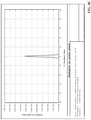
- FIGs. 8A-8C are plots illustrating a predicted radiance at a distance of one meter from an illuminator comprising a light source device (e.g., a VCSEL light source device) that projects a beam through lens 300.
- FIG. 8A is a plot of radiance in angle space of -50 degrees to +50 degrees.
- FIG. 8B is a plot of radiance over the horizontal cross-section.
- FIG. 8C is a plot of radiance over the vertical cross-section, indicating a narrow beam having an expansion of less than 2 degrees. In the horizontal plane spanning the angle of 50 degrees the homogeneity is at least 85%.
- Embodiments of the arched cylindrical Fresnel lens described herein can be fabricated to have a thin light construction, and afford effective light gathering ability that prove useful in a variety of light gathering applications.
- Example applications in which embodiments of lens 300 can be used include, but are not limited to, condenser systems, emitter/detector architectures, imaging systems, or three-dimensional sensing systems such as time-of-flight cameras.
- Lens 300 (or elementary units 600 or 700) can also be an integrated component of an industrial optical safety device, such as a laser scanner or a light guard.
- lens 300 can be used to efficiently direct light to a monitored industrial area, and a corresponding receiver can detect presence of people or objects within the monitored area based on measurement of the illumination (e.g., by measuring a portion of the illumination reflected from the person or object, or by monitoring the illumination in a through-beam architecture).
- Embodiments of lens 300 can also be used to direct laser light in laser radar (Lidar) systems.
- FIGs 9-10 illustrate various methodologies in accordance with one or more examples not falling under the scope of protection. While, for purposes of simplicity of explanation, the one or more methodologies shown herein are shown and described as a series of acts, it is to be understood and appreciated that the subject innovation is not limited by the order of acts, as some acts may, in accordance therewith, occur in a different order and/or concurrently with other acts from that shown and described herein. For example, those skilled in the art will understand and appreciate that a methodology could alternatively be represented as a series of interrelated states or events, such as in a state diagram. Moreover, not all illustrated acts may be required to implement a methodology in accordance with the innovation.
- interaction diagram(s) may represent methodologies, or methods, in accordance with the subject disclosure when disparate entities enact disparate portions of the methodologies.
- two or more of the disclosed example methods can be implemented in combination with each other, to accomplish one or more features or advantages described herein.
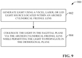
- FIG. 9 illustrates an example methodology for projecting a collimated light beam.
- a light source device e.g., a VCSEL, laser, or LED light source - located within an arched cylindrical Fresnel lens.
- the Fresnel lens can have a curved profile of substantially any arched shape, including but not limited ty cylindrical, elliptical, parabolic, hyperbolic, or a freeform arched shape.
- the light generated at step 902 is collimated in the sagittal plane by the arched cylindrical Fresnel lens while being permitted to propagate in the orthogonal plane with little or no refraction of the light rays, thereby yielding an FOI having a disk-like shape (or a disk sector).
- Collimation by the lens can be achieved using one or more of refractive grooves or diffraction gratings formed on the lens, or by holographic phase patterns formed on a surface of the lens or within the bulk of the lens.
- FIG. 10 illustrates an example methodology for processing and projecting light into an illumination field.
- a light source device such as a VCSEL, laser, or LED light source.
- the light generated at step 1002 is collimated in the tangential plane and expanded in the sagittal plane using a cylindrical negative lens to yield first collimated light.
- the light may alternatively be collected from the light source using biconic lenses.
- the first collimated light is directed to an optical diffuser using a planar mirror.
- the optical diffuser can be a refractive or diffractive device that scatters and homogenizes the beam in the tangential plane.
- the diffuser may also comprise two lens arrays set in tandem to one another.
- the first collimated light is homogenized and expanded using the optical diffuser to yield a homogenized beam.
- the homogenized beam is collimated in the sagittal plane using an arched cylindrical Fresnel lens, which also allows the homogenized beam to propagate in the orthogonal plane to yield second collimated light.
- Collimation by the lens can be achieved using one or more of refractive grooves or diffraction gratings formed on the lens, or by holographic phase patterns formed on a surface of the lens or within the bulk of the lens.
- exemplary is used to mean serving as an example, instance, or illustration. Any aspect or design described herein as "exemplary” is not necessarily to be construed as preferred or advantageous over other aspects or designs. Rather, use of the word exemplary is intended to present concepts in a concrete fashion.
Claims (11)
- Système d'éclairage, comprenant :une lentille arquée (300) ayant un profil incurvé qui forme un arc autour d'un axe de ligne centrale vertical (332) pour produire un profil cylindrique creux, dans lequel la lentille arquée est diffractive et/ou réfractive ; etun dispositif de source d'éclairage (740) disposé au niveau ou à proximité d'un foyer du profil incurvé de la lentille arquée, comprenant :une source de lumière (722) émettant un rayonnement le long de l'axe de ligne centrale vers une lentille négative cylindrique (724),la lentille négative cylindrique (724) qui élargit la lumière provenant de la source de lumière dans des plans sagittaux, chacun formé par un locus de rayons incidents sur une ligne verticale (304) sur une surface intérieure de la lentille arquée,un diffuseur optique (726) qui diffuse et homogénéise la lumière dans le plan tangentiel défini par des locus d'axes optiques du profil cylindrique et ainsi perpendiculaire aux plans sagittaux, etun ensemble de miroirs plans (728) qui plient la lumière à 90 degrés et l'orientent vers la surface intérieure de la lentille arquée,dans lequel la lentille arquée collimate la lumière dans les plans sagittaux et facilite une propagation non perturbée du faisceau collimaté dans le plan tangentiel, etdans lequel la source d'éclairage pivote le long de l'axe de ligne centrale, et le faisceau de sortie comprend une forme conique ayant un angle d'inclinaison par rapport au plan tangentiel qui est dynamiquement modulé proportionnellement à une amplitude à laquelle la source d'éclairage pivote.
- Système d'éclairage de la revendication 1, dans lequel la lentille arquée comprend des rainures angulaires parallèles qui traversent une surface du corps de lentille le long d'un profil incurvé du corps de lentille.
- Système d'éclairage de l'une des revendications précédentes, dans lequel la lentille arquée comprend un matériau à gradient d'indice de réfraction.
- Système d'éclairage de l'une des revendications précédentes, dans lequel une surface de la lentille arquée comprend une structure binaire qui attribue une puissance optique diffractive.
- Système d'éclairage de l'une des revendications précédentes, dans lequel la lentille arquée comprend un motif de phase imprimé holographiquement en volume dans une masse de la lentille arquée et/ou un motif de phase imprimé holographiquement sur une surface de la lentille arquée.
- Système d'éclairage de l'une des revendications précédentes, dans lequel la lentille arquée comprend un motif de phase imprimé holographiquement formé sur un film avec une colle à motif holographique, et le film est fixé sur un substrat de la lentille arquée.
- Système d'éclairage de l'une des revendications précédentes, dans lequel la forme cylindrique creuse comprend un profil incurvé qui est de forme circulaire, elliptique, parabolique, hyperbolique ou libre.
- Système d'éclairage de la revendication 1, dans lequel la lentille arquée collimate le faisceau de sortie élargi dans un premier plan et permet une propagation du faisceau de sortie élargi dans un deuxième plan qui est orthogonal au premier plan pour produire un faisceau de sortie.
- Système d'éclairage de la revendication 8, dans lequel :lorsque le dispositif de source d'éclairage est positionné au niveau ou à proximité d'une intersection de l'axe de ligne centrale du profil cylindrique de la lentille arquée et du plan tangentiel, le faisceau de sortie est sensiblement parallèle au plan tangentiel ; etlorsque le dispositif de source d'éclairage est positionné le long d'un axe de ligne centrale du profil cylindrique de la lentille arquée décalé par rapport à une intersection entre l'axe de ligne centrale et le plan tangentiel, le faisceau de sortie est incliné selon un certain angle par rapport au plan tangentiel.
- Système d'éclairage de l'une des revendications 1 à 9, dans lequel :l'au moins une région optique comprend des rainures angulaires parallèles sur une surface de la lentille arquée, et où les rainures angulaires parallèles s'étendent le long du profil incurvé de la lentille arquée ; et/oula lentille arquée comprend un matériau à gradient d'indice de réfraction ; et/ouune surface de la lentille arquée comprend une structure binaire qui attribue une puissance optique diffractive ; et/oula lentille arquée comprend un motif de phase imprimé holographiquement en volume dans une masse de la lentille arquée et/ou un motif de phase imprimé holographiquement sur une surface de la lentille arquée.
- Procédé de production d'un faisceau de lumière, comprenant :la génération (902) d'une lumière par une source de lumière, où la génération comprend :l'émission d'une lumière de source par une source d'éclairage (722) située au niveau ou à proximité d'un foyer d'une lentille arquée, la lentille arquée ayant un profil incurvé qui forme un arc autour d'un axe de ligne centrale vertical pour produire un profil cylindrique creux,dans lequel la lentille arquée est réfractive et/ou diffractive, et la source de lumière émet un rayonnement le long de l'axe de ligne centrale vers une lentille négative cylindrique (724) ;l'élargissement, via la lentille négative cylindrique, de la lumière dans des plans sagittaux, chacun formé par un locus de rayons incidents sur une ligne verticale (304) sur une surface intérieure de la lentille arquée ;la diffusion et l'homogénéisation, par un diffuseur optique (726), de la lumière dans un plan tangentiel défini par des locus d'axes optiques du profil cylindrique et ainsi perpendiculaire aux plans sagittaux ;l'orientation, par un ensemble de miroirs plans (628) qui plient la lumière à 90 degrés, de la lumière vers la surface intérieure de la lentille arquée ayant le profil incurvé qui forme un arc autour d'un axe de ligne centrale ; etla collimation (904), par la lentille arquée, de la lumière dans les plans sagittaux tout en facilitant une propagation non perturbée de la lumière dans le plan tangentiel,dans lequel la source d'éclairage pivote le long d'un axe de ligne centrale (332) et le faisceau de sortie comprend une forme conique ayant un angle d'inclinaison par rapport au plan tangentiel qui est dynamiquement modulé proportionnellement à une amplitude à laquelle la source d'éclairage pivote.
Applications Claiming Priority (1)
| Application Number | Priority Date | Filing Date | Title |
|---|---|---|---|
| US15/828,739 US10436953B2 (en) | 2017-12-01 | 2017-12-01 | Arched collimating lens forming a disk-like illumination |
Publications (2)
| Publication Number | Publication Date |
|---|---|
| EP3492960A1 EP3492960A1 (fr) | 2019-06-05 |
| EP3492960B1 true EP3492960B1 (fr) | 2022-02-23 |
Family
ID=64564567
Family Applications (1)
| Application Number | Title | Priority Date | Filing Date |
|---|---|---|---|
| EP18209028.2A Active EP3492960B1 (fr) | 2017-12-01 | 2018-11-29 | Lentille de collimation arquée formant un éclairage semblables à un disque |
Country Status (2)
| Country | Link |
|---|---|
| US (1) | US10436953B2 (fr) |
| EP (1) | EP3492960B1 (fr) |
Families Citing this family (3)
| Publication number | Priority date | Publication date | Assignee | Title |
|---|---|---|---|---|
| DE102019123217A1 (de) * | 2019-08-29 | 2021-03-04 | Sick Ag | Laserscanner |
| US10746905B1 (en) * | 2019-09-23 | 2020-08-18 | Rosemount Aerospace Inc. | Optical systems with toroidal fresnel lenses |
| JP7463782B2 (ja) | 2020-03-17 | 2024-04-09 | 富士フイルムビジネスイノベーション株式会社 | 発光素子アレイ、発光装置、光学装置、計測装置及び情報処理装置 |
Citations (2)
| Publication number | Priority date | Publication date | Assignee | Title |
|---|---|---|---|---|
| US5642933A (en) * | 1993-12-29 | 1997-07-01 | Patlite Corporation | Light source structure for signal indication lamp |
| EP1298382A1 (fr) * | 2001-09-28 | 2003-04-02 | Osram-Sylvania Inc. | Ampoule à DEL remplacable avec élément optique interchangeable |
Family Cites Families (33)
| Publication number | Priority date | Publication date | Assignee | Title |
|---|---|---|---|---|
| US5235467A (en) * | 1990-03-23 | 1993-08-10 | Zeni Lite Buoy Co., Limited | Cylindrical lens and a manufacturing method for the same |
| CA2079620A1 (fr) * | 1991-10-25 | 1993-04-26 | Roeland M. T. Hekker | Elements holographiques pour systeme d'enregistrement optique |
| US5612821A (en) | 1995-06-15 | 1997-03-18 | United Technologies Corporation | Micro lens system for controlling an optical beam pattern |
| US6830189B2 (en) | 1995-12-18 | 2004-12-14 | Metrologic Instruments, Inc. | Method of and system for producing digital images of objects with subtantially reduced speckle-noise patterns by illuminating said objects with spatially and/or temporally coherent-reduced planar laser illumination |
| US6243513B1 (en) * | 1997-12-13 | 2001-06-05 | Lightchip, Inc. | Wavelength division multiplexing/demultiplexing devices using diffractive optic lenses |
| US6583937B1 (en) | 1998-11-30 | 2003-06-24 | Carl-Zeiss Stiftung | Illuminating system of a microlithographic projection exposure arrangement |
| US6563612B1 (en) * | 2000-08-07 | 2003-05-13 | Physical Optics Corporation | Collimating screen simulator and method |
| US6433934B1 (en) | 2000-08-11 | 2002-08-13 | Yakov Reznichenko | Illumination system for use in imaging systems |
| JP2002072132A (ja) | 2000-08-30 | 2002-03-12 | Dainippon Screen Mfg Co Ltd | 照明装置 |
| US6631016B1 (en) | 2001-07-18 | 2003-10-07 | Zebra Imaging, Inc. | Full-parallax holographic stereograms on curved substrates |
| US7159986B2 (en) | 2002-05-20 | 2007-01-09 | Swales & Associates, Inc. | Wide field collimator |
| CN1886981A (zh) | 2003-10-31 | 2006-12-27 | Vkb有限公司 | 用于虚拟接口投影和感应的光学装置 |
| US7619824B2 (en) | 2003-11-18 | 2009-11-17 | Merlin Technology Limited Liability Company | Variable optical arrays and variable manufacturing methods |
| US7268950B2 (en) | 2003-11-18 | 2007-09-11 | Merlin Technology Limited Liability Company | Variable optical arrays and variable manufacturing methods |
| JP4616577B2 (ja) | 2004-04-22 | 2011-01-19 | 株式会社日立製作所 | 映像表示装置 |
| JP4843344B2 (ja) | 2005-03-18 | 2011-12-21 | 株式会社リコー | 照明装置及び画像読取装置 |
| WO2008129552A1 (fr) | 2007-04-19 | 2008-10-30 | Dvp Technologies Ltd. | Système et procédé de prise d'image destinés à la surveillance d'un champ de regard |
| GB2469693A (en) | 2009-04-25 | 2010-10-27 | Optovate Ltd | A controllable light directional distributor for an illumination apparatus |
| US8803967B2 (en) | 2009-07-31 | 2014-08-12 | Mesa Imaging Ag | Time of flight camera with rectangular field of illumination |
| US8596823B2 (en) | 2010-09-07 | 2013-12-03 | Coherent, Inc. | Line-projection apparatus for arrays of diode-laser bar stacks |
| KR101798063B1 (ko) | 2010-12-14 | 2017-11-15 | 삼성전자주식회사 | 조명 광학계 및 이를 포함하는 3차원 영상 획득 장치 |
| NL2008009A (en) | 2011-02-02 | 2012-08-06 | Asml Netherlands Bv | Illumination system, lithographic apparatus and method. |
| US9551914B2 (en) | 2011-03-07 | 2017-01-24 | Microsoft Technology Licensing, Llc | Illuminator with refractive optical element |
| US8908159B2 (en) | 2011-05-11 | 2014-12-09 | Leddartech Inc. | Multiple-field-of-view scannerless optical rangefinder in high ambient background light |
| JP5724755B2 (ja) | 2011-08-26 | 2015-05-27 | 株式会社リコー | 撮像システム |
| DE102012207931A1 (de) | 2012-01-07 | 2013-07-11 | Johnson Controls Gmbh | Kameraanordnung zur Distanzmessung |
| JP5910485B2 (ja) | 2012-03-16 | 2016-04-27 | 株式会社リコー | 撮像システム |
| EP2875315B1 (fr) | 2012-07-23 | 2018-09-05 | Ricoh Company, Ltd. | Caméra stéréoscopique |
| US9696427B2 (en) | 2012-08-14 | 2017-07-04 | Microsoft Technology Licensing, Llc | Wide angle depth detection |
| US20150287638A1 (en) * | 2014-04-04 | 2015-10-08 | Jungrae Park | Hybrid wafer dicing approach using collimated laser scribing process and plasma etch |
| CN203892962U (zh) | 2014-05-28 | 2014-10-22 | 上海开腾信号设备有限公司 | 一种中小直径高光强led环射信号灯 |
| US9798126B2 (en) | 2015-08-25 | 2017-10-24 | Rockwell Automation Technologies, Inc. | Modular illuminator for extremely wide field of view |
| CN107065159B (zh) | 2017-03-24 | 2019-10-18 | 南京理工大学 | 一种基于大照明数值孔径的大视场高分辨率显微成像装置及迭代重构方法 |
-
2017
- 2017-12-01 US US15/828,739 patent/US10436953B2/en active Active
-
2018
- 2018-11-29 EP EP18209028.2A patent/EP3492960B1/fr active Active
Patent Citations (2)
| Publication number | Priority date | Publication date | Assignee | Title |
|---|---|---|---|---|
| US5642933A (en) * | 1993-12-29 | 1997-07-01 | Patlite Corporation | Light source structure for signal indication lamp |
| EP1298382A1 (fr) * | 2001-09-28 | 2003-04-02 | Osram-Sylvania Inc. | Ampoule à DEL remplacable avec élément optique interchangeable |
Also Published As
| Publication number | Publication date |
|---|---|
| US20190170913A1 (en) | 2019-06-06 |
| EP3492960A1 (fr) | 2019-06-05 |
| US10436953B2 (en) | 2019-10-08 |
Similar Documents
| Publication | Publication Date | Title |
|---|---|---|
| JP7269712B2 (ja) | メタレンズを含むプロジェクタ | |
| US9841496B2 (en) | Multiple pattern illumination optics for time of flight system | |
| EP3144586B1 (fr) | Illuminateur modulaire pour très large champ de vision | |
| EP3492960B1 (fr) | Lentille de collimation arquée formant un éclairage semblables à un disque | |
| US11209634B2 (en) | Optical system | |
| JP5606137B2 (ja) | 光学ユニット | |
| CN111699417B (zh) | 光学系统 | |
| US10609266B2 (en) | Camera for wide field of view with an arbitrary aspect ratio | |
| CA2974124A1 (fr) | Systeme de determination de portee, reflecteur panoramique integre et collecteur panoramique | |
| WO2008138156A9 (fr) | Système d'éclairage | |
| CN114911065A (zh) | 光投射装置 | |
| CN114173107A (zh) | 结构光模组及电子设备 | |
| JP2007534973A (ja) | 照明の集光および整形に関する装置および方法 | |
| JP5361903B2 (ja) | オプトエレクトロニクス装置および画像記録装置 | |
| CN110320673B (zh) | 光学模块和用于投影的方法 | |
| TWI785400B (zh) | 光源、感測器及照明場景的方法 | |
| CN114944589A (zh) | 具有扩展场照明的光源 | |
| CN209821513U (zh) | 一种直下式光学投射系统 | |
| RU120747U1 (ru) | Светоизлучающий диодный модуль | |
| US10871262B2 (en) | Structured light illumination module | |
| WO2019099847A1 (fr) | Système optique | |
| KR100188953B1 (ko) | 액정프로젝트의 조명장치 | |
| JP2016167370A (ja) | 光源装置および光電式変位検出装置 |
Legal Events
| Date | Code | Title | Description |
|---|---|---|---|
| PUAI | Public reference made under article 153(3) epc to a published international application that has entered the european phase |
Free format text: ORIGINAL CODE: 0009012 |
|
| STAA | Information on the status of an ep patent application or granted ep patent |
Free format text: STATUS: THE APPLICATION HAS BEEN PUBLISHED |
|
| AK | Designated contracting states |
Kind code of ref document: A1 Designated state(s): AL AT BE BG CH CY CZ DE DK EE ES FI FR GB GR HR HU IE IS IT LI LT LU LV MC MK MT NL NO PL PT RO RS SE SI SK SM TR |
|
| AX | Request for extension of the european patent |
Extension state: BA ME |
|
| STAA | Information on the status of an ep patent application or granted ep patent |
Free format text: STATUS: REQUEST FOR EXAMINATION WAS MADE |
|
| 17P | Request for examination filed |
Effective date: 20191115 |
|
| RBV | Designated contracting states (corrected) |
Designated state(s): AL AT BE BG CH CY CZ DE DK EE ES FI FR GB GR HR HU IE IS IT LI LT LU LV MC MK MT NL NO PL PT RO RS SE SI SK SM TR |
|
| STAA | Information on the status of an ep patent application or granted ep patent |
Free format text: STATUS: EXAMINATION IS IN PROGRESS |
|
| 17Q | First examination report despatched |
Effective date: 20200722 |
|
| STAA | Information on the status of an ep patent application or granted ep patent |
Free format text: STATUS: EXAMINATION IS IN PROGRESS |
|
| RIC1 | Information provided on ipc code assigned before grant |
Ipc: G01S 17/89 20200101ALN20210816BHEP Ipc: G01S 17/08 20060101ALN20210816BHEP Ipc: G02B 26/10 20060101ALI20210816BHEP Ipc: F21V 5/04 20060101ALI20210816BHEP Ipc: G02B 3/08 20060101ALI20210816BHEP Ipc: G02B 19/00 20060101AFI20210816BHEP |
|
| GRAP | Despatch of communication of intention to grant a patent |
Free format text: ORIGINAL CODE: EPIDOSNIGR1 |
|
| STAA | Information on the status of an ep patent application or granted ep patent |
Free format text: STATUS: GRANT OF PATENT IS INTENDED |
|
| INTG | Intention to grant announced |
Effective date: 20210930 |
|
| GRAS | Grant fee paid |
Free format text: ORIGINAL CODE: EPIDOSNIGR3 |
|
| GRAA | (expected) grant |
Free format text: ORIGINAL CODE: 0009210 |
|
| STAA | Information on the status of an ep patent application or granted ep patent |
Free format text: STATUS: THE PATENT HAS BEEN GRANTED |
|
| AK | Designated contracting states |
Kind code of ref document: B1 Designated state(s): AL AT BE BG CH CY CZ DE DK EE ES FI FR GB GR HR HU IE IS IT LI LT LU LV MC MK MT NL NO PL PT RO RS SE SI SK SM TR |
|
| REG | Reference to a national code |
Ref country code: GB Ref legal event code: FG4D |
|
| REG | Reference to a national code |
Ref country code: CH Ref legal event code: EP |
|
| REG | Reference to a national code |
Ref country code: AT Ref legal event code: REF Ref document number: 1470897 Country of ref document: AT Kind code of ref document: T Effective date: 20220315 |
|
| REG | Reference to a national code |
Ref country code: IE Ref legal event code: FG4D |
|
| REG | Reference to a national code |
Ref country code: DE Ref legal event code: R096 Ref document number: 602018031164 Country of ref document: DE |
|
| REG | Reference to a national code |
Ref country code: LT Ref legal event code: MG9D |
|
| REG | Reference to a national code |
Ref country code: NL Ref legal event code: MP Effective date: 20220223 |
|
| REG | Reference to a national code |
Ref country code: AT Ref legal event code: MK05 Ref document number: 1470897 Country of ref document: AT Kind code of ref document: T Effective date: 20220223 |
|
| PG25 | Lapsed in a contracting state [announced via postgrant information from national office to epo] |
Ref country code: SE Free format text: LAPSE BECAUSE OF FAILURE TO SUBMIT A TRANSLATION OF THE DESCRIPTION OR TO PAY THE FEE WITHIN THE PRESCRIBED TIME-LIMIT Effective date: 20220223 Ref country code: RS Free format text: LAPSE BECAUSE OF FAILURE TO SUBMIT A TRANSLATION OF THE DESCRIPTION OR TO PAY THE FEE WITHIN THE PRESCRIBED TIME-LIMIT Effective date: 20220223 Ref country code: PT Free format text: LAPSE BECAUSE OF FAILURE TO SUBMIT A TRANSLATION OF THE DESCRIPTION OR TO PAY THE FEE WITHIN THE PRESCRIBED TIME-LIMIT Effective date: 20220623 Ref country code: NO Free format text: LAPSE BECAUSE OF FAILURE TO SUBMIT A TRANSLATION OF THE DESCRIPTION OR TO PAY THE FEE WITHIN THE PRESCRIBED TIME-LIMIT Effective date: 20220523 Ref country code: NL Free format text: LAPSE BECAUSE OF FAILURE TO SUBMIT A TRANSLATION OF THE DESCRIPTION OR TO PAY THE FEE WITHIN THE PRESCRIBED TIME-LIMIT Effective date: 20220223 Ref country code: LT Free format text: LAPSE BECAUSE OF FAILURE TO SUBMIT A TRANSLATION OF THE DESCRIPTION OR TO PAY THE FEE WITHIN THE PRESCRIBED TIME-LIMIT Effective date: 20220223 Ref country code: HR Free format text: LAPSE BECAUSE OF FAILURE TO SUBMIT A TRANSLATION OF THE DESCRIPTION OR TO PAY THE FEE WITHIN THE PRESCRIBED TIME-LIMIT Effective date: 20220223 Ref country code: ES Free format text: LAPSE BECAUSE OF FAILURE TO SUBMIT A TRANSLATION OF THE DESCRIPTION OR TO PAY THE FEE WITHIN THE PRESCRIBED TIME-LIMIT Effective date: 20220223 Ref country code: BG Free format text: LAPSE BECAUSE OF FAILURE TO SUBMIT A TRANSLATION OF THE DESCRIPTION OR TO PAY THE FEE WITHIN THE PRESCRIBED TIME-LIMIT Effective date: 20220523 |
|
| PG25 | Lapsed in a contracting state [announced via postgrant information from national office to epo] |
Ref country code: PL Free format text: LAPSE BECAUSE OF FAILURE TO SUBMIT A TRANSLATION OF THE DESCRIPTION OR TO PAY THE FEE WITHIN THE PRESCRIBED TIME-LIMIT Effective date: 20220223 Ref country code: LV Free format text: LAPSE BECAUSE OF FAILURE TO SUBMIT A TRANSLATION OF THE DESCRIPTION OR TO PAY THE FEE WITHIN THE PRESCRIBED TIME-LIMIT Effective date: 20220223 Ref country code: GR Free format text: LAPSE BECAUSE OF FAILURE TO SUBMIT A TRANSLATION OF THE DESCRIPTION OR TO PAY THE FEE WITHIN THE PRESCRIBED TIME-LIMIT Effective date: 20220524 Ref country code: FI Free format text: LAPSE BECAUSE OF FAILURE TO SUBMIT A TRANSLATION OF THE DESCRIPTION OR TO PAY THE FEE WITHIN THE PRESCRIBED TIME-LIMIT Effective date: 20220223 Ref country code: AT Free format text: LAPSE BECAUSE OF FAILURE TO SUBMIT A TRANSLATION OF THE DESCRIPTION OR TO PAY THE FEE WITHIN THE PRESCRIBED TIME-LIMIT Effective date: 20220223 |
|
| PG25 | Lapsed in a contracting state [announced via postgrant information from national office to epo] |
Ref country code: IS Free format text: LAPSE BECAUSE OF FAILURE TO SUBMIT A TRANSLATION OF THE DESCRIPTION OR TO PAY THE FEE WITHIN THE PRESCRIBED TIME-LIMIT Effective date: 20220623 |
|
| PG25 | Lapsed in a contracting state [announced via postgrant information from national office to epo] |
Ref country code: SM Free format text: LAPSE BECAUSE OF FAILURE TO SUBMIT A TRANSLATION OF THE DESCRIPTION OR TO PAY THE FEE WITHIN THE PRESCRIBED TIME-LIMIT Effective date: 20220223 Ref country code: SK Free format text: LAPSE BECAUSE OF FAILURE TO SUBMIT A TRANSLATION OF THE DESCRIPTION OR TO PAY THE FEE WITHIN THE PRESCRIBED TIME-LIMIT Effective date: 20220223 Ref country code: RO Free format text: LAPSE BECAUSE OF FAILURE TO SUBMIT A TRANSLATION OF THE DESCRIPTION OR TO PAY THE FEE WITHIN THE PRESCRIBED TIME-LIMIT Effective date: 20220223 Ref country code: EE Free format text: LAPSE BECAUSE OF FAILURE TO SUBMIT A TRANSLATION OF THE DESCRIPTION OR TO PAY THE FEE WITHIN THE PRESCRIBED TIME-LIMIT Effective date: 20220223 Ref country code: DK Free format text: LAPSE BECAUSE OF FAILURE TO SUBMIT A TRANSLATION OF THE DESCRIPTION OR TO PAY THE FEE WITHIN THE PRESCRIBED TIME-LIMIT Effective date: 20220223 Ref country code: CZ Free format text: LAPSE BECAUSE OF FAILURE TO SUBMIT A TRANSLATION OF THE DESCRIPTION OR TO PAY THE FEE WITHIN THE PRESCRIBED TIME-LIMIT Effective date: 20220223 |
|
| REG | Reference to a national code |
Ref country code: DE Ref legal event code: R097 Ref document number: 602018031164 Country of ref document: DE |
|
| PG25 | Lapsed in a contracting state [announced via postgrant information from national office to epo] |
Ref country code: AL Free format text: LAPSE BECAUSE OF FAILURE TO SUBMIT A TRANSLATION OF THE DESCRIPTION OR TO PAY THE FEE WITHIN THE PRESCRIBED TIME-LIMIT Effective date: 20220223 |
|
| PLBE | No opposition filed within time limit |
Free format text: ORIGINAL CODE: 0009261 |
|
| STAA | Information on the status of an ep patent application or granted ep patent |
Free format text: STATUS: NO OPPOSITION FILED WITHIN TIME LIMIT |
|
| 26N | No opposition filed |
Effective date: 20221124 |
|
| PG25 | Lapsed in a contracting state [announced via postgrant information from national office to epo] |
Ref country code: SI Free format text: LAPSE BECAUSE OF FAILURE TO SUBMIT A TRANSLATION OF THE DESCRIPTION OR TO PAY THE FEE WITHIN THE PRESCRIBED TIME-LIMIT Effective date: 20220223 |
|
| P01 | Opt-out of the competence of the unified patent court (upc) registered |
Effective date: 20230404 |
|
| PG25 | Lapsed in a contracting state [announced via postgrant information from national office to epo] |
Ref country code: MC Free format text: LAPSE BECAUSE OF FAILURE TO SUBMIT A TRANSLATION OF THE DESCRIPTION OR TO PAY THE FEE WITHIN THE PRESCRIBED TIME-LIMIT Effective date: 20220223 |
|
| REG | Reference to a national code |
Ref country code: CH Ref legal event code: PL |
|
| REG | Reference to a national code |
Ref country code: BE Ref legal event code: MM Effective date: 20221130 |
|
| PG25 | Lapsed in a contracting state [announced via postgrant information from national office to epo] |
Ref country code: LI Free format text: LAPSE BECAUSE OF NON-PAYMENT OF DUE FEES Effective date: 20221130 Ref country code: IT Free format text: LAPSE BECAUSE OF FAILURE TO SUBMIT A TRANSLATION OF THE DESCRIPTION OR TO PAY THE FEE WITHIN THE PRESCRIBED TIME-LIMIT Effective date: 20220223 Ref country code: CH Free format text: LAPSE BECAUSE OF NON-PAYMENT OF DUE FEES Effective date: 20221130 |
|
| PG25 | Lapsed in a contracting state [announced via postgrant information from national office to epo] |
Ref country code: LU Free format text: LAPSE BECAUSE OF NON-PAYMENT OF DUE FEES Effective date: 20221129 |
|
| PG25 | Lapsed in a contracting state [announced via postgrant information from national office to epo] |
Ref country code: IE Free format text: LAPSE BECAUSE OF NON-PAYMENT OF DUE FEES Effective date: 20221129 |
|
| PG25 | Lapsed in a contracting state [announced via postgrant information from national office to epo] |
Ref country code: BE Free format text: LAPSE BECAUSE OF NON-PAYMENT OF DUE FEES Effective date: 20221130 |
|
| PGFP | Annual fee paid to national office [announced via postgrant information from national office to epo] |
Ref country code: GB Payment date: 20231019 Year of fee payment: 6 |
|
| PGFP | Annual fee paid to national office [announced via postgrant information from national office to epo] |
Ref country code: FR Payment date: 20231019 Year of fee payment: 6 Ref country code: DE Payment date: 20231019 Year of fee payment: 6 |
|
| PG25 | Lapsed in a contracting state [announced via postgrant information from national office to epo] |
Ref country code: HU Free format text: LAPSE BECAUSE OF FAILURE TO SUBMIT A TRANSLATION OF THE DESCRIPTION OR TO PAY THE FEE WITHIN THE PRESCRIBED TIME-LIMIT; INVALID AB INITIO Effective date: 20181129 |