EP3492883B1 - Tank mit volumenmesssystem - Google Patents
Tank mit volumenmesssystem Download PDFInfo
- Publication number
- EP3492883B1 EP3492883B1 EP18203253.2A EP18203253A EP3492883B1 EP 3492883 B1 EP3492883 B1 EP 3492883B1 EP 18203253 A EP18203253 A EP 18203253A EP 3492883 B1 EP3492883 B1 EP 3492883B1
- Authority
- EP
- European Patent Office
- Prior art keywords
- liquid
- tank
- sensors
- cavity
- volume
- Prior art date
- Legal status (The legal status is an assumption and is not a legal conclusion. Google has not performed a legal analysis and makes no representation as to the accuracy of the status listed.)
- Active
Links
Images


Classifications
-
- G—PHYSICS
- G01—MEASURING; TESTING
- G01F—MEASURING VOLUME, VOLUME FLOW, MASS FLOW OR LIQUID LEVEL; METERING BY VOLUME
- G01F22/00—Methods or apparatus for measuring volume of fluids or fluent solid material, not otherwise provided for
-
- G—PHYSICS
- G01—MEASURING; TESTING
- G01F—MEASURING VOLUME, VOLUME FLOW, MASS FLOW OR LIQUID LEVEL; METERING BY VOLUME
- G01F25/00—Testing or calibration of apparatus for measuring volume, volume flow or liquid level or for metering by volume
-
- G—PHYSICS
- G01—MEASURING; TESTING
- G01F—MEASURING VOLUME, VOLUME FLOW, MASS FLOW OR LIQUID LEVEL; METERING BY VOLUME
- G01F25/00—Testing or calibration of apparatus for measuring volume, volume flow or liquid level or for metering by volume
- G01F25/0084—Testing or calibration of apparatus for measuring volume, volume flow or liquid level or for metering by volume for measuring volume
-
- G—PHYSICS
- G01—MEASURING; TESTING
- G01F—MEASURING VOLUME, VOLUME FLOW, MASS FLOW OR LIQUID LEVEL; METERING BY VOLUME
- G01F23/00—Indicating or measuring liquid level or level of fluent solid material, e.g. indicating in terms of volume or indicating by means of an alarm
-
- G—PHYSICS
- G01—MEASURING; TESTING
- G01F—MEASURING VOLUME, VOLUME FLOW, MASS FLOW OR LIQUID LEVEL; METERING BY VOLUME
- G01F23/00—Indicating or measuring liquid level or level of fluent solid material, e.g. indicating in terms of volume or indicating by means of an alarm
- G01F23/22—Indicating or measuring liquid level or level of fluent solid material, e.g. indicating in terms of volume or indicating by means of an alarm by measuring physical variables, other than linear dimensions, pressure or weight, dependent on the level to be measured, e.g. by difference of heat transfer of steam or water
- G01F23/26—Indicating or measuring liquid level or level of fluent solid material, e.g. indicating in terms of volume or indicating by means of an alarm by measuring physical variables, other than linear dimensions, pressure or weight, dependent on the level to be measured, e.g. by difference of heat transfer of steam or water by measuring variations of capacity or inductance of capacitors or inductors arising from the presence of liquid or fluent solid material in the electric or electromagnetic fields
-
- G—PHYSICS
- G01—MEASURING; TESTING
- G01F—MEASURING VOLUME, VOLUME FLOW, MASS FLOW OR LIQUID LEVEL; METERING BY VOLUME
- G01F23/00—Indicating or measuring liquid level or level of fluent solid material, e.g. indicating in terms of volume or indicating by means of an alarm
- G01F23/22—Indicating or measuring liquid level or level of fluent solid material, e.g. indicating in terms of volume or indicating by means of an alarm by measuring physical variables, other than linear dimensions, pressure or weight, dependent on the level to be measured, e.g. by difference of heat transfer of steam or water
- G01F23/28—Indicating or measuring liquid level or level of fluent solid material, e.g. indicating in terms of volume or indicating by means of an alarm by measuring physical variables, other than linear dimensions, pressure or weight, dependent on the level to be measured, e.g. by difference of heat transfer of steam or water by measuring the variations of parameters of electromagnetic or acoustic waves applied directly to the liquid or fluent solid material
-
- G—PHYSICS
- G01—MEASURING; TESTING
- G01F—MEASURING VOLUME, VOLUME FLOW, MASS FLOW OR LIQUID LEVEL; METERING BY VOLUME
- G01F23/00—Indicating or measuring liquid level or level of fluent solid material, e.g. indicating in terms of volume or indicating by means of an alarm
- G01F23/80—Arrangements for signal processing
Definitions
- the invention relates to the field of volume measurement systems in a tank and more particularly in an aircraft turbojet oil tank.
- the published patent document EP 0 289 172 A2 describes an aircraft fuel tank. This includes several capacitive gauges (denoted 4, 6, 8, 10) to measure the quantity of fuel at different places in the tank. By combining the measurements of the capacitive gauges, it is possible to calculate a total volume of fuel. This is particularly useful for evaluating a correct measurement of the volume of fuel in a tank of complex shape and in which the fuel moves according to the movements of the aircraft.
- This document also shows that in order to prevent a failure of one of the capacitive gauges, two methods can be envisaged, one requiring significant calculation means and the other being imprecise. Neither of the two methods is therefore entirely satisfactory.
- the tank of this document is of fairly simple shape and such a volume measurement system is therefore not suitable for tanks of more complex shape which cannot receive capacitive gauges embedded in the fuel. Such a volume measurement system is also not suitable for a turbojet oil tank.
- the object of the invention is to overcome at least one of the drawbacks of the above-mentioned state of the art. More particularly, the object of the invention is to provide a volume measurement system which is more reliable and more flexible in the sense that it can be adapted to any shape of tank and to all flight conditions.
- the subject of the invention is an aircraft turbojet reservoir, and in particular an aircraft turbojet oil reservoir, the reservoir comprising: a cavity capable of containing a liquid; an envelope delimiting the cavity; and a device for measuring the volume of liquid contained in said cavity; remarkable in that the measuring device comprises at least three point sensors for detecting liquid, said at least three point sensors being arranged on the casing so as to describe a polygon; the measuring device being configured to estimate the total volume of liquid contained in the cavity by triangulation from the measurements of at least three point sensors.
- An aircraft turbojet tank has particular properties enabling it to withstand in particular extreme temperatures, vibrations, corrosion and shocks.
- the measuring device can estimate the volume of liquid by means of a calculation module receiving signals sent by the sensors.
- the at least three point sensors define a plane whose intersection with the envelope defines a section of the tank, the measuring device being configured to calculate the proportion of said section and / or the proportion of the area. of said polygon which is occupied by the liquid in order to estimate the total volume of liquid.
- the calculation can be made on the basis of the information relayed by the sensors, without necessarily taking into account all the sensors or all the combinations of sensors forming the polygon.
- the at least three sensors comprise at least one transmitter and at least one receiver
- the volume measuring device comprising a switch for sequentially measuring the electrical signals transmitted by several predefined combinations of transceivers. , at least two combinations consisting of the same transmitter with two respective different receivers and / or at least two combinations consisting of the same receiver with two respective different transmitters, the switch being automatically switched according to a cycle consisting of all the combinations predefined and the measuring device being configured to evaluate the total volume of the liquid from the signals recorded during a cycle.
- the measuring device is programmed to take an average of the liquid volume values calculated for several cycles.
- the at least three point sensors comprise one or two transmitter (s) emitting radiation and respectively two or one receiver (s) capable of receiving this radiation, the radiation being acoustic or electro -magnetic, in particular X-ray, Ultra-violet or Infrared, the measuring device calculating the partial absorption of the radiation by the liquid present between the emitter (s) and the receiver (s).
- the point sensors are capacitive proximity sensors or ultrasound probes capable of detecting the presence of liquid in their vicinity.
- the point sensors comprise one or more anodes and one or more cathodes capable of forming capacitive gauges, the measuring device calculating the proportion of liquid occupying each anode-cathode segment by measuring the electrical capacitance between each anode and each cathode.
- the cavity in the normal direction of assembly, has a height, the at least three point sensors being distributed over the majority or the entire height of the cavity and / or the at least three point sensors define between them a plurality of triangles sweeping the majority of the cavity and / or the at least three point sensors are distributed over the circumference of the envelope.
- the point sensors are arranged on the outer face of the envelope.
- the envelope has at least one transparent portion in line with the point sensors.
- At most four sensors are arranged at coplanar points.
- the at least three point sensors comprise at least four or at least six point sensors defining a polyhedron.
- the point sensors in the normal direction of mounting of the reservoir, define several superimposed triangles, the measuring device being configured to estimate the volume of liquid contained in the cavity by triangulation from said superimposed triangles.
- the measuring device is programmed to detect an abnormal signal, to identify as faulty the sensor generating this signal, and to ignore this abnormal signal in the calculation of the total volume of liquid.
- the invention also relates to a method of implementing a reservoir which is remarkable in that the reservoir is according to one of the embodiments described above, the method comprising a step of calibrating the device for determining the quantity. volume of liquid, during which are recorded reference signals emitted by the sensors when the tank is empty and when the tank is full, and / or for known values of liquid volume for different orientations of the tank.
- the sensors prior to calibration, are arranged randomly on the periphery of the cavity of the reservoir.
- the material making up the envelope has a lower permittivity than that of the liquid intended to be received in the cavity.
- a faulty sensor is replaced and the calibration of the replacement sensor is carried out by learning as a function of the signals emitted by the other sensors and possibly of the signals of the faulty sensor before it is detected as failing, and learning lasts until a confidence index is reached.
- the invention also relates to a method for determining the volume of liquid in a reservoir, the reservoir comprising geometric points at the periphery of the cavity which the liquid may occupy, the method comprising: a step of determining the proportion of the defined segment by the position of two geometric points, which is occupied by the liquid; and / or a step of determining the proportion of area of a polygon defined by the position of three or more coplanar geometric points, which is occupied by the liquid; and / or a step of determining the proportion of the area of a section defined by the intersection of a plane defined by a polygon of three or more coplanar geometric points and of the cavity of the reservoir, which is occupied by the liquid ; and a step of determining the total volume of liquid from the proportions of segment and / or polygon and / or section occupied by the liquid for several possible combinations of points, the proportions of segment and / or polygon and / or of surface occupied by the liquid being measured using point sensors positioned on said geometric points.
- an arithmetic mean of said proportions weighted by the length of the segments and / or the area of the polygons and / or the area of the section, for several or all possible combinations of geometric points is calculated.
- an initial calibration step makes it possible to define proportions of 0% when the reservoir is empty and of 100% when the reservoir is full for all the segments and / or all the polygons and / or all sections.
- the sensor concerned when a proportion of segment and / or polygon and / or section occupied by the liquid, calculated from the measurements of the sensors, is not between 0 and 100%, the sensor concerned, if necessary identified by cross-checking several measurements for several combinations of sensors, is excluded from the possible combinations of geometric points.
- a sufficient number of sensors is provided in the tank to obtain a calculation of the total volume within an acceptable tolerance margin, whatever the inclination of the tank and whatever the filling rate. of the tank.
- a series of tests is performed iteratively by adding a sensor to each iteration and comparing the exact known value of liquid in the reservoir with the value calculated from the sensor data for various inclinations of the sensor. As long as the measured value diverges from the actual value beyond a tolerance threshold for at least one inclination, the process should be repeated by adding a sensor.
- each subject of the invention is also applicable to the other subjects of the invention.
- Each object of the invention can be combined with other objects, and the objects of the invention can also be combined with the embodiments of the description, which in addition can be combined with each other, according to all the possible technical combinations, unless the contrary is true. is not explicitly mentioned.
- the figure 1 describes an example of a reservoir according to the invention.
- the reservoir 1 has an internal cavity 2 which can accommodate a liquid.
- the cavity is delimited by an envelope 3.
- the reservoir of the figure 1 is schematically represented in the form of a cylinder but the reservoir of the invention can take any other form. In the case of an aircraft turbojet oil reservoir, the reservoir may have a particularly complex shape.
- Points 4.1, 4.2, 4.3 are occupied by three sensors.
- a sensor can be an emitter, a receiver, an anode, a cathode, or a combination thereof.
- the sensor can be of different types to detect different physical or chemical quantities.
- the sensors can be positioned on the interior side of the casing 3 or on its exterior side. When the sensors are positioned outside the envelope 3, transparent portions or at least allowing the transmitted and received signals to pass are arranged in the envelope.
- the sensors can include transmitters and receivers able to work together.
- Transmitters can emit acoustic or electromagnetic radiation which is perceived by the receivers.
- point 4.1 can accommodate a transmitter of electromagnetic waves and points 4.2 and 4.3 can accommodate receivers to receive said waves.
- the waves received by the receivers are compared to the waves emitted (in amplitude, frequency, phase shift, etc.) and it is therefore possible to know the quantity of liquid through which the waves have passed. Indeed, after having calibrated the empty and full system, it is possible to know which proportions of the segments [4.1, 4.2] and [4.1, 4.3] are occupied by the liquid.
- the sensors can also be of the capacitive proximity sensor or ultrasonic probe type.
- the points of triangle T can be occupied by ultrasound probes. Each can be oriented towards the other two. With these probes, it is possible to map the presence of liquid in the triangle T.
- the three maps of the three sensors can be superimposed to obtain a complete and precise “image” of the section.
- Certain types of waves may be more or less suitable for certain types of liquids and a person skilled in the art would know how to adapt the nature of the waves employed as a function of the liquid received in the reservoir.
- the triangle T defines a plane P passing through the three points 4.1, 4.2, 4.3.
- the figure 2 shows the section of reservoir 1 in plane P.
- the plane P defined by points 4.1, 4.2 and 4.3 of triangle T intersects reservoir 1 in a section S which in our example is an ellipse.
- the hatched area corresponds to the presence of liquid.
- the liquid does not necessarily occupy a lower zone of the reservoir with a horizontal level.
- the attenuation of the electromagnetic signals between an emitter and the two receivers makes it possible to define the proportion of the segments of the triangle which is occupied by the liquid.
- an average weighted by the length of the segments it is possible to estimate the proportion of the area of the triangle which is occupied by the liquid. This estimate is therefore an extrapolation of the proportions of the segments occupied by the liquid.
- a point of the triangle can include several sensors.
- the proportions of segments occupied by the liquid can be estimated for all segments of the triangle or for only two segments. It is thus possible to optimize the calculation time or to perform redundancy checks.
- the sensors positioned on the triangle make it possible to map the zone occupied by the liquid and to deduce therefrom by image analysis a proportion of the triangle T and / or of the section S which is occupied by the liquid.
- the proportion of liquid occupying triangle T makes it possible to give a good approximation of the proportion of liquid occupying the tank, and knowing the total volume of the tank, deduce therefrom the total volume of liquid in the reservoir.
- the sensors are preferably positioned over the majority of the height of the cavity and distributed over its circumference.
- the figure 3 describes another example of a reservoir according to the invention.
- the shape of the tank is more complex.
- the reservoir 10 comprises a large number of points denoted 14.n, n ranging from 1 to the total number of points.
- Each group of three points 14.n forms a triangle Tn.
- a given point 14.n can form a large number of triangles with any two other points 14.n.
- On the figure 3 only a few of the triangles Tn are shown for the sake of clarity of the drawing.
- the planes defined by the triangles Tn intersect the reservoir to form sections (not shown).
- the segment, triangle and / or section proportions can be combined to estimate the volume of liquid. Depending on the shape of the tank in particular, it may be more judicious to use one of the proportions (for example that of the sections) rather than another (for example that of the triangles). For another form of tank, a combination of the two with a larger weighting factor, for example, for the proportion of liquid present in the triangle, can be used.
- more than three coplanar points are provided and these form a polygon with more than three sides.
- the proportions of each segment which are occupied by the liquid can be measured and the total volume of the liquid can be calculated.
- the same principle can be applied in space. For example, 4 points on the periphery of the reservoir forming a tetrahedron are provided with sensors. The measured signals make it possible to establish a proportion by volume of the tetrahedron which is occupied by the liquid and then to extrapolate to the total volume of the reservoir. When a multitude of points are provided at the periphery of the cavity, combinations of tetrahedra or polyhedra can be predefined and the proportion of the volume of each polyhedron which is occupied by the liquid can be estimated before deducing the total volume. liquid in the reservoir.
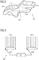
- the figure 4 represents a switch 20. It is usually possible to operate all the sensors simultaneously. Thus, if for example several transmitters and a single receiver operate at the same time, a decomposition of the signal (for example in Fourier series) makes it possible to find the signal amplitude coming from each of the transmitters transmitting at different frequencies and thus estimate the signal attenuation and therefore the quantity of liquid between the transmitter and each of the receivers.
- a decomposition of the signal for example in Fourier series
- At least one transmitter and at least one receiver are activated simultaneously and the signals at their terminals are received by a calculation module 30.
- These signals can be an electrical capacitor between the transmitting terminal and the receiving terminal, or signals between the terminal. earth and transmitter, compared with signals between earth and receiver.
- the switch 20 can comprise a portion 20A for selecting the transmitter or transmitters and a portion 20B for selecting the receiver or receivers thus defining a combination.
- a number of transmitter (s) -receiver (s) combinations is defined and switch 20 successively cycles through all the states corresponding to these combinations.
- the figure 4 is a simplified diagram. Wired or wireless communication means can be provided between the sensors and the calculation module.
- the value of the volume of liquid in the tank which is communicated to the user can be an average of the liquid values calculated for several cycles, in order to smooth out the measurement inaccuracies in particular when the tank is subjected to rapid movements.
- the figure 5 describes a method of using a reservoir according to the invention.
- the sensors are calibrated. For example, one or more measurement cycles as described above are carried out with the tank empty and with the tank completely full. This allows the signals from the sensors to be recorded under extreme empty and full conditions.
- measurements for other known liquid levels can be carried out, and this can be carried out with varying orientations of the reservoir.
- This calibration technique allows the sensors to be placed randomly on the tank.
- the system does not need to "know” where the sensors are located, nor to know the geometry of the tank. Even if the accuracy of the measurement will be favored by a multitude of sensors arranged over the entire tank, the measurement system can operate with only three sensors.
- a step 102 is an ordinary measurement step.
- the different combinations of sensors emit signals, which allow the evaluation of the volume of liquid in the tank in accordance with the examples illustrated above.
- a sensor fails. This can give rise to abnormal signals detected during a step 104. This step may never occur, hence the dashed arrow.
- An abnormal signal is such that the proportion of liquid occupying a segment / polygon / section / polyhedron is calculated to be less than 0% or greater than 100%.
- a step 106 of identifying the faulty sensor is necessary. This can be do this by intersecting several segments / polygons / sections / polyhedra in order to isolate the faulty sensor.
- the measurements are carried out according to a step 108 during which the combinations of sensors comprising the faulty sensor are excluded from the combinations of sensors determined for a measurement cycle.
- the tank is equipped with multiple sensors, the absence of a sensor in the measurement has only a limited impact on the validity of the measurement.
- the faulty sensor is replaced in step 110.
- the replacement sensor can be randomly placed on the reservoir but preferably it will be positioned in the vicinity of the position of the faulty sensor which can be removed.
- an initial calibration step can be performed again, this is the route indicated by A on the figure 5 .
- the system should be able to continue operating without re-calibrating each failed sensor. This is the channel indicated by B.
- the system will both measure the volume of liquid and attempt to calibrate the replacement sensor, that is to say evaluate the empty and full reference signals, and / or for arbitrary values of liquid. This step is detailed in figure 6 .
- step 112 if the sensor is considered to be calibrated, a new ordinary measurement 102 can be performed. As long as the sensor is not considered calibrated, the process returns to step 112.
- the figure 6 illustrates in detail the volume measurement step 112 with a replacement sensor.
- a first optional step 1120 consists in measuring the proportions of segments / polygons / sections / polyhedra in the vicinity of the faulty sensor which are occupied by the liquid.
- the neighborhood can be defined as combinations of sensors for which the proportion of liquid was approximately equal, within a tolerance threshold (10% for example), at combinations of sensors encompassing the failed sensor, before it fails.
- a second optional step 1122 consists in estimating the proportion occupied by the liquid of the segments / polygons / sections / polyhedra of which the replacement sensor forms a point.
- a step of assignment 1124 of the reference values of the replacement sensor is carried out.
- the total volume of the liquid in the reservoir is calculated, taking into account the reference values of step 1124 and possibly the values of the proportions of step 1122 of the replacement sensor .
- the volume of liquid in the tank is also calculated without taking into account the replacement sensor, that is to say by excluding combinations of sensors, the replacement sensor.
- step 114 the difference between the volumes of liquid in the reservoir calculated with and without the replacement sensor is calculated. If this difference is greater than a confidence threshold (for example 3%), the process continues in step 116 which indicates to the user a volume of liquid calculated without the replacement sensor.
- a confidence threshold for example 3%
- the estimated reference values for the replacement sensor are kept and the next measurement cycle will be an ordinary measurement 102.
- the confidence threshold can be chosen according to the geometry of the reservoir or the expected measurement accuracy. It can be determined by experimental method or by numerical simulation.
- Redundancy of measurements is possible by multiplying the number of sensors. A good compromise between measurement reliability and device simplicity can be obtained when there are no more than four coplanar sensors.
- the number of sensors to be mounted on the tank can be defined experimentally by providing as many as necessary so that whatever the volume of liquid and whatever the orientation of the tank, an accuracy within an acceptable tolerance margin (for example 1 %) is reached. This number of sensors can be defined by experimental study or by numerical simulation.
- the wall does not play a preponderant role in the attenuation of the electromagnetic waves.
- the material of the wall, at least opposite the sensors, can therefore be chosen such that it does not penalize the detection of the liquid.
- the technologies can be combined for the same tank, for example depending on the geometry of the tank, certain technologies being limited or inadequate for distances that are too great between the emitter and the receiver or conversely for distances that are too small.
Landscapes
- Physics & Mathematics (AREA)
- Fluid Mechanics (AREA)
- General Physics & Mathematics (AREA)
- Measurement Of Levels Of Liquids Or Fluent Solid Materials (AREA)
Claims (15)
- Tank (1, 10) für ein Flugzeug-Turbostrahltriebwerk, insbesondere ein Öltank für ein Flugzeug-Turbostrahltriebwerk, wobei der Tank Folgendes umfasst:- einen Hohlraum (2), der eine Flüssigkeit aufnehmen kann;- eine Hülle (3), die den Hohlraum (2) begrenzt; und- eine Vorrichtung (4.1, 4.2, 4.3, 14.n, 20, 30) zur Messung des in dem Hohlraum (2) enthaltenen Flüssigkeitsvolumens;dadurch gekennzeichnet, dass:die Messvorrichtung (4.1, 4.2, 4.3, 14.n, 20, 30) mindestens drei Punktsensoren zum Nachweis von Flüssigkeit umfasst, wobei die mindestens drei Punktsensoren auf der Hülle so angeordnet sind, dass sie ein Polygon (T, Tn) beschreiben;die Messvorrichtung (4.1, 4.2, 4.3, 14.n, 20, 30) so ausgelegt ist, dass sie das Gesamtvolumen der im Hohlraum enthaltenen Flüssigkeit durch Triangulation auf Grundlage der Messungen der mindestens drei Punktsensoren schätzt;und dass die mindestens drei Punktsensoren eine Ebene (P) definieren, deren Schnitt mit der Hülle einen Querschnitt (S) des Tanks (1) definiert, wobei die Messvorrichtung (4.1, 4.2, 4.3, 14.n, 20, 30) so ausgelegt ist, dass sie den Anteil des genannten Querschnitts (S) und/oder den Anteil der Fläche des genannten Polygons, der von der Flüssigkeit eingenommen wird, berechnet, um das Gesamtvolumen der Flüssigkeit zu schätzen.
- Tank nach Anspruch 1, dadurch gekennzeichnet, dass die mindestens drei Sensoren mindestens einen Sender und mindestens einen Empfänger umfassen, wobei die Volumenmessvorrichtung einen Schalter (20) zur sequentiellen Messung der von einer Vielzahl von vordefinierten Sender-Empfänger-Kombinationen ausgesandten Signale umfasst, mindestens zwei Kombinationen, bestehend aus demselben Sender mit jeweils zwei verschiedenen Empfängern und/oder mindestens zwei Kombinationen, bestehend aus demselben Empfänger mit jeweils zwei verschiedenen Sendern, wobei der Schalter (20) in einem Zyklus, bestehend aus allen vorgegebenen Kombinationen, automatisch umgeschaltet wird und wobei die Messvorrichtung (4.1, 4.2, 4.3, 14.n, 20, 30) dazu ausgelegt ist, aus den während eines Zyklus aufgenommenen Signalen das Gesamtvolumen der Flüssigkeit auszuwerten.
- Tank nach Anspruch 2, dadurch gekennzeichnet, dass die Messvorrichtung (4.1, 4.2, 4.3, 14.n, 20, 30) so ausgelegt ist, über mehrere Zyklen berechnete Flüssigkeitsvolumenwerte zu mitteln.
- Tank nach einem der Ansprüche 1 bis 3, dadurch gekennzeichnet, dass die mindestens drei Punktsensoren: (i) einen oder zwei Sender, die Strahlung aussenden, und jeweils zwei oder einen oder mehrere Empfänger umfassen, die in der Lage sind, diese Strahlung zu empfangen, wobei die Strahlung akustisch oder elektromagnetisch ist, insbesondere Röntgen-, Ultraviolett- oder Infrarotstrahlung, wobei die Messvorrichtung die Teilabsorption der Strahlung durch die zwischen dem (den) Sendern und dem (den) Empfängern) vorhandene Flüssigkeit berechnet; (ii) kapazitive Näherungssensoren oder Ultraschallsonden sind, die in der Lage sind, das Vorhandensein von Flüssigkeit in ihrer Nähe zu erfassen; oder (iii) eine oder mehrere Anoden und eine oder mehrere Kathoden umfassen, die in der Lage sind, kapazitive Messgeräte zu bilden, wobei die Messvorrichtung den Anteil der Flüssigkeit, der jedes Anoden-Kathoden-Segment einnimmt, durch Messung der elektrischen Kapazität zwischen jeder Anode und jeder Kathode berechnet.
- Tank nach einem der Ansprüche 1 bis 4, dadurch gekennzeichnet, dass der Hohlraum in der normalen Einbaurichtung eine Höhe aufweist, wobei die mindestens drei Punktsensoren über die Mehrheit oder die gesamte Höhe des Hohlraums (2) verteilt sind und die mindestens drei Punktsensoren zwischen sich eine Vielzahl von Dreiecken definieren, die die Mehrheit des Hohlraums (2) abtasten und/oder die mindestens drei Punktsensoren über den Umfang des Gehäuses (3) verteilt sind.
- Tank nach einem der Ansprüche 1 bis 5, dadurch gekennzeichnet, dass die Punktsensoren an der Außenseite des Gehäuses (3) angeordnet sind, wobei das Gehäuse (3) vorzugsweise mindestens einen transparenten Abschnitt vor den Punktsensoren aufweist.
- Tank nach einem der Ansprüche 1 bis 6, dadurch gekennzeichnet, dass die mindestens drei Punktsensoren mindestens vier oder mindestens sechs Punktsensoren umfassen, die einen Polyeder definieren.
- Tank nach den Ansprüchen 1 bis 7, dadurch gekennzeichnet, dass die Punktsensoren in der normalen Einbaurichtung des Tanks eine Vielzahl von übereinanderliegenden Dreiecken definieren, insbesondere in Abhängigkeit von der Messrichtung des Füllstands im Tank, wobei die Messvorrichtung (4.1, 4.2, 4.3, 14.n, 20, 30) so ausgelegt ist, dass sie das in dem Hohlraum enthaltene Flüssigkeitsvolumen durch Triangulation ausgehend von den übereinanderliegenden Dreiecken schätzt.
- Verfahren zum Betreiben eines Tanks (1, 10), dadurch gekennzeichnet, dass der Tank (1, 10) einem der Ansprüche 1 bis 8 entspricht, wobei das Verfahren einen Kalibrierungsschritt (100) einer Vorrichtung zur Bestimmung des Flüssigkeitsvolumens umfasst, wobei in diesem Schritt von Sensoren ausgesandte Referenzsignale aufgezeichnet werden, wenn der Tank (1), 10) leer ist und wenn der Tank (1, 10) voll ist, und/oder für bekannte Werte des Flüssigkeitsvolumens für verschiedene Ausrichtungen des Tanks (1, 10), und dass vor der Kalibrierung (100) die Sensoren zufällig am Umfang des Hohlraums (2) des Tanks (1, 10) angeordnet sind.
- Verfahren nach Anspruch 9, dadurch gekennzeichnet, dass das die Hülle (3) bildende Material eine Dielektrizitätskonstante aufweist, die niedriger ist als die der in dem Hohlraum (2) aufzunehmenden Flüssigkeit.
- Verfahren nach einem der Ansprüche 9 bis 10, dadurch gekennzeichnet, dass ein defekter Sensor ersetzt wird und die Kalibrierung des Ersatzsensors durch Einlernen in Abhängigkeit von den Signalen der anderen Sensoren und gegebenenfalls den Signalen des defekten Sensors durchgeführt wird, bevor dieser als defekt erkannt wird, und das Einlernen so lange dauert, bis ein Vertrauensindex erreicht ist.
- Verfahren zur Bestimmung des Flüssigkeitsvolumens in einem Tank (1, 10), wobei der Tank geometrische Punkte (4.1, 4.2, 4.3, 14.n) am Umfang des Hohlraums (2) aufweist, die von der Flüssigkeit eingenommen werden können, wobei das Verfahren Folgendes umfasst:- einen Schritt zur Bestimmung des Anteils des durch die Position zweier geometrischer Punkte (4.1, 4.2) definierten Segments ([4.1, 4.2]), das von der Flüssigkeit eingenommen wird; und/oder- einen Schritt zur Bestimmung des Flächenanteils eines Polygons (T, Tn), das durch die Position von drei oder mehr koplanaren geometrischen Punkten definiert ist, das von der Flüssigkeit eingenommen wird; und/oder- ein Schritt zur Bestimmung des Flächenanteils eines Querschnitts (S), der durch den Schnittpunkt einer durch ein Polygon von drei oder mehr koplanaren geometrischen Punkten (4.1, 4.2, 4.3) definierten Ebene mit dem Hohlraum (2) des Behälters (1, 10), der von der Flüssigkeit eingenommen wird, definiert ist;- und einen Schritt zur Bestimmung des Gesamtvolumens der Flüssigkeit aus dem von der Flüssigkeit eingenommenen Segment- und/oder Polygon- und/oder Querschnittsverhältnissen für mehrere mögliche Kombinationen von Punkten (4.1, 4.2, 4.3, 14.n),- wobei die Anteile von Segment und/oder Polygon und/oder Oberfläche, die von der Flüssigkeit eingenommen werden, die mit Hilfe von Punktsensoren gemessen wird, die auf den geometrischen Punkten (4.1, 4.2, 4.3, 14.n) positioniert sind.
- Verfahren nach Anspruch 12, dadurch gekennzeichnet, dass in dem Schritt der Bestimmung des Gesamtvolumens der Flüssigkeit ein arithmetisches Mittel dieser Anteile, gewichtet mit der Länge der Segmente ([4.1, 4.2], [4.1, 4.3]) und/oder der Fläche der Polygone (T, Tn) und/oder der Fläche des Querschnitts (S), für mehrere oder alle möglichen Kombinationen von geometrischen Punkten berechnet wird.
- Verfahren nach Anspruch 12 oder 13, dadurch gekennzeichnet, dass ein anfänglicher Kalibrierungsschritt (100) verwendet wird, um Anteile von 0 %, wenn der Tank leer ist, und 100 %, wenn der Tank voll ist, für alle Segmente ([4.1, 4.2], [4.1, 4.3]) und/oder alle Polygone (T, Tn) und/oder alle Abschnitte (S) zu definieren.
- Verfahren nach einem der Ansprüche 12 bis 14, dadurch gekennzeichnet, dass, wenn ein aus den Sensormessungen berechneter Anteil des von der Flüssigkeit eingenommenen Segments ([4.1, 4.2], [4.1, 4.3]) und/oder Polygons (T, Tn) und/oder Querschnitts (S), der von der Flüssigkeit eingenommen wird, nicht zwischen 0 und 100 % liegt, der betreffende Sensor, der gegebenenfalls durch Abruf (106) mehrerer Messungen für mehrere Sensorkombinationen identifiziert wird, von den möglichen Kombinationen geometrischer Punkte ausgeschlossen wird.
Applications Claiming Priority (1)
| Application Number | Priority Date | Filing Date | Title |
|---|---|---|---|
| BE2017/5865A BE1025751B1 (fr) | 2017-11-29 | 2017-11-29 | Reservoir avec systeme de mesure de volume |
Publications (2)
| Publication Number | Publication Date |
|---|---|
| EP3492883A1 EP3492883A1 (de) | 2019-06-05 |
| EP3492883B1 true EP3492883B1 (de) | 2021-03-10 |
Family
ID=60781411
Family Applications (1)
| Application Number | Title | Priority Date | Filing Date |
|---|---|---|---|
| EP18203253.2A Active EP3492883B1 (de) | 2017-11-29 | 2018-10-30 | Tank mit volumenmesssystem |
Country Status (2)
| Country | Link |
|---|---|
| EP (1) | EP3492883B1 (de) |
| BE (1) | BE1025751B1 (de) |
Family Cites Families (9)
| Publication number | Priority date | Publication date | Assignee | Title |
|---|---|---|---|---|
| EP0289172B1 (de) | 1987-04-28 | 1992-06-10 | Simmonds Precision Products Inc. | Apparat und Methode zum Bestimmen einer Flüssigkeitsmenge |
| DE4014990A1 (de) * | 1990-05-10 | 1991-11-14 | Herbert Prof Dr Zott | Vorrichtung zur bestimmung des fluessigkeitsstandes einer fluessigkeit in einem behaelter |
| DE4025326C2 (de) * | 1990-05-10 | 1994-03-03 | Krieg Gunther | Verfahren und Vorrichtung zum Messen der Flüssigkeitshöhe einer bewegten Flüssigkeit in einem Behälter |
| GB9102195D0 (en) * | 1991-02-01 | 1991-03-20 | Smiths Industries Plc | Liquid quantity gauging |
| GB9520235D0 (en) * | 1995-10-04 | 1995-12-06 | Smiths Industries Plc | Fluid quantity gauging systems |
| US11988539B2 (en) * | 2013-10-09 | 2024-05-21 | Parker-Hannifin Corporation | Aircraft fluid gauging techniques using pressure measurements and optical sensors |
| US9952084B2 (en) * | 2013-10-10 | 2018-04-24 | Apm Automation Solutions Ltd | Increasing signal to noise ratio of acoustic echoes by a group of spaced apart acoustic transceiver arrays |
| CN103674181A (zh) * | 2013-12-04 | 2014-03-26 | 江苏大学 | 动态液位超声检测装置与方法 |
| US10448875B2 (en) * | 2015-10-15 | 2019-10-22 | Stream DX, Inc | Capacitive measurement device with integrated electrical and mechanical shielding |
-
2017
- 2017-11-29 BE BE2017/5865A patent/BE1025751B1/fr not_active IP Right Cessation
-
2018
- 2018-10-30 EP EP18203253.2A patent/EP3492883B1/de active Active
Non-Patent Citations (1)
| Title |
|---|
| None * |
Also Published As
| Publication number | Publication date |
|---|---|
| EP3492883A1 (de) | 2019-06-05 |
| BE1025751A1 (fr) | 2019-06-27 |
| BE1025751B1 (fr) | 2019-07-04 |
Similar Documents
| Publication | Publication Date | Title |
|---|---|---|
| EP2661636B1 (de) | Verfahren und vorrichtung zur bestimmung der bewegungen einer flüssigkeit aus fernmessungen radialer geschwindigkeiten | |
| FR3006770A1 (fr) | Procede et dispositif de metrologie pour la calibration de la geometrie d'un reseau de balises acoustiques sous-marines | |
| FR2975782A1 (fr) | Systeme et procede pour positionner par doppler des capteurs sismiques | |
| FR2703727A1 (fr) | Procédé et dispositif pour déterminer une correction de profondeur pour un outil de diagraphie dans un puits de pétrole. | |
| EP3374795B1 (de) | Auf höhenfehler korrigiertes bathymetrisches system und bathymetrisches verfahren | |
| EP2517051B1 (de) | Verfahren und vorrichtung zur ermittlung einer teilmenge von messergebnissen, verfahren und system zur ortung eines objekts, aufzeichnungsmedium für diese verfahren | |
| FR2527339A1 (fr) | Procede et installation pour analyser des discontinuites situees dans un milieu sensiblement homogene | |
| EP3850394B1 (de) | Verfahren zur bestimmung einer tiefe oder eines bathymetrischen profils auf basis eines mittleren schallgeschwindigkeitsprofils, verfahren zur bestimmung solch eines geschwindigkeitsprofils und zugehöriges sonarsystem | |
| FR3095693A1 (fr) | Procédé de navigation à double filtre | |
| EP3492883B1 (de) | Tank mit volumenmesssystem | |
| WO2019115971A1 (fr) | Dispositif, installation et procede d'imagerie de defauts d'une structure par emission et reception d'ondes mecaniques dans cette structure | |
| FR3149692A1 (fr) | procédé de surveillance de l’état d’un réservoir destiné à contenir un liquide | |
| FR3035919A1 (fr) | Procede et dispositif de surveillance d'une consommation d'huile contenue dans un reservoir d'un moteur d'aeronef | |
| WO2020152244A1 (fr) | Système et procédé de mesure par ondes acoustiques du niveau de remplissage d'un réservoir de fluide | |
| CN111971102A (zh) | 测量滤饼厚度的装置和方法 | |
| EP2909580B1 (de) | Navigationssystem und -verfahren eines beweglichen fahrzeugs geeignet zum bestimmen und anzeigen einer sicherheits-navigationszone | |
| EP2491424B1 (de) | Verfahren zur simultanen ortung und kartierung über elastische nichtlineare filterung | |
| FR3074573A1 (fr) | Procede de mesure par ultrasons | |
| FR2915278A1 (fr) | Systeme de releve des hauteurs comprenant une regle telescopique a deux extremites cooperant avec un faisceau optique a balayage dans un plan horizontal. | |
| CA3082926C (fr) | Procede d'amelioration des acquisitions sismiques mettant en oeuvre des systemes actifs ultralegers de detection sismique | |
| WO2011061413A1 (fr) | Procede pour positionner un puits par rapport a une image sismique du sous-sol | |
| WO2024074780A1 (fr) | Procédé de contrôle de l'intégrité d'une pluralité de mesures de pseudo-distances acquises par un système de navigation | |
| FR3129470A1 (fr) | Procédé de mesure d’un niveau de remplissage d’une benne | |
| WO2023233112A1 (fr) | Procédé et système de recherche d'une balise par un dispositif de détection | |
| FR3121993A1 (fr) | Dispositif électronique de mesure et d’enregistrement pour l’évaluation d’un fluide corporel drainé |
Legal Events
| Date | Code | Title | Description |
|---|---|---|---|
| PUAI | Public reference made under article 153(3) epc to a published international application that has entered the european phase |
Free format text: ORIGINAL CODE: 0009012 |
|
| STAA | Information on the status of an ep patent application or granted ep patent |
Free format text: STATUS: THE APPLICATION HAS BEEN PUBLISHED |
|
| AK | Designated contracting states |
Kind code of ref document: A1 Designated state(s): AL AT BE BG CH CY CZ DE DK EE ES FI FR GB GR HR HU IE IS IT LI LT LU LV MC MK MT NL NO PL PT RO RS SE SI SK SM TR |
|
| AX | Request for extension of the european patent |
Extension state: BA ME |
|
| STAA | Information on the status of an ep patent application or granted ep patent |
Free format text: STATUS: REQUEST FOR EXAMINATION WAS MADE |
|
| 17P | Request for examination filed |
Effective date: 20191114 |
|
| RBV | Designated contracting states (corrected) |
Designated state(s): AL AT BE BG CH CY CZ DE DK EE ES FI FR GB GR HR HU IE IS IT LI LT LU LV MC MK MT NL NO PL PT RO RS SE SI SK SM TR |
|
| RIC1 | Information provided on ipc code assigned before grant |
Ipc: G01F 22/00 20060101ALI20200225BHEP Ipc: G01F 23/26 20060101ALN20200225BHEP Ipc: G01F 23/28 20060101ALN20200225BHEP Ipc: G01F 23/00 20060101ALN20200225BHEP Ipc: G01F 25/00 20060101AFI20200225BHEP |
|
| GRAP | Despatch of communication of intention to grant a patent |
Free format text: ORIGINAL CODE: EPIDOSNIGR1 |
|
| STAA | Information on the status of an ep patent application or granted ep patent |
Free format text: STATUS: GRANT OF PATENT IS INTENDED |
|
| RIC1 | Information provided on ipc code assigned before grant |
Ipc: G01F 23/28 20060101ALN20200420BHEP Ipc: G01F 23/26 20060101ALN20200420BHEP Ipc: G01F 22/00 20060101ALI20200420BHEP Ipc: G01F 23/00 20060101ALN20200420BHEP Ipc: G01F 25/00 20060101AFI20200420BHEP |
|
| INTG | Intention to grant announced |
Effective date: 20200508 |
|
| GRAJ | Information related to disapproval of communication of intention to grant by the applicant or resumption of examination proceedings by the epo deleted |
Free format text: ORIGINAL CODE: EPIDOSDIGR1 |
|
| STAA | Information on the status of an ep patent application or granted ep patent |
Free format text: STATUS: REQUEST FOR EXAMINATION WAS MADE |
|
| INTC | Intention to grant announced (deleted) | ||
| GRAP | Despatch of communication of intention to grant a patent |
Free format text: ORIGINAL CODE: EPIDOSNIGR1 |
|
| STAA | Information on the status of an ep patent application or granted ep patent |
Free format text: STATUS: GRANT OF PATENT IS INTENDED |
|
| RIC1 | Information provided on ipc code assigned before grant |
Ipc: G01F 23/26 20060101ALN20201001BHEP Ipc: G01F 22/00 20060101ALI20201001BHEP Ipc: G01F 23/28 20060101ALN20201001BHEP Ipc: G01F 23/00 20060101ALN20201001BHEP Ipc: G01F 25/00 20060101AFI20201001BHEP |
|
| INTG | Intention to grant announced |
Effective date: 20201028 |
|
| GRAS | Grant fee paid |
Free format text: ORIGINAL CODE: EPIDOSNIGR3 |
|
| GRAA | (expected) grant |
Free format text: ORIGINAL CODE: 0009210 |
|
| STAA | Information on the status of an ep patent application or granted ep patent |
Free format text: STATUS: THE PATENT HAS BEEN GRANTED |
|
| AK | Designated contracting states |
Kind code of ref document: B1 Designated state(s): AL AT BE BG CH CY CZ DE DK EE ES FI FR GB GR HR HU IE IS IT LI LT LU LV MC MK MT NL NO PL PT RO RS SE SI SK SM TR |
|
| REG | Reference to a national code |
Ref country code: GB Ref legal event code: FG4D Free format text: NOT ENGLISH |
|
| REG | Reference to a national code |
Ref country code: AT Ref legal event code: REF Ref document number: 1370331 Country of ref document: AT Kind code of ref document: T Effective date: 20210315 Ref country code: CH Ref legal event code: EP |
|
| REG | Reference to a national code |
Ref country code: IE Ref legal event code: FG4D Free format text: LANGUAGE OF EP DOCUMENT: FRENCH |
|
| REG | Reference to a national code |
Ref country code: DE Ref legal event code: R096 Ref document number: 602018013666 Country of ref document: DE |
|
| REG | Reference to a national code |
Ref country code: LT Ref legal event code: MG9D |
|
| PG25 | Lapsed in a contracting state [announced via postgrant information from national office to epo] |
Ref country code: NO Free format text: LAPSE BECAUSE OF FAILURE TO SUBMIT A TRANSLATION OF THE DESCRIPTION OR TO PAY THE FEE WITHIN THE PRESCRIBED TIME-LIMIT Effective date: 20210610 Ref country code: LT Free format text: LAPSE BECAUSE OF FAILURE TO SUBMIT A TRANSLATION OF THE DESCRIPTION OR TO PAY THE FEE WITHIN THE PRESCRIBED TIME-LIMIT Effective date: 20210310 Ref country code: HR Free format text: LAPSE BECAUSE OF FAILURE TO SUBMIT A TRANSLATION OF THE DESCRIPTION OR TO PAY THE FEE WITHIN THE PRESCRIBED TIME-LIMIT Effective date: 20210310 Ref country code: GR Free format text: LAPSE BECAUSE OF FAILURE TO SUBMIT A TRANSLATION OF THE DESCRIPTION OR TO PAY THE FEE WITHIN THE PRESCRIBED TIME-LIMIT Effective date: 20210611 Ref country code: FI Free format text: LAPSE BECAUSE OF FAILURE TO SUBMIT A TRANSLATION OF THE DESCRIPTION OR TO PAY THE FEE WITHIN THE PRESCRIBED TIME-LIMIT Effective date: 20210310 Ref country code: BG Free format text: LAPSE BECAUSE OF FAILURE TO SUBMIT A TRANSLATION OF THE DESCRIPTION OR TO PAY THE FEE WITHIN THE PRESCRIBED TIME-LIMIT Effective date: 20210610 |
|
| REG | Reference to a national code |
Ref country code: AT Ref legal event code: MK05 Ref document number: 1370331 Country of ref document: AT Kind code of ref document: T Effective date: 20210310 |
|
| REG | Reference to a national code |
Ref country code: NL Ref legal event code: MP Effective date: 20210310 |
|
| PG25 | Lapsed in a contracting state [announced via postgrant information from national office to epo] |
Ref country code: LV Free format text: LAPSE BECAUSE OF FAILURE TO SUBMIT A TRANSLATION OF THE DESCRIPTION OR TO PAY THE FEE WITHIN THE PRESCRIBED TIME-LIMIT Effective date: 20210310 Ref country code: RS Free format text: LAPSE BECAUSE OF FAILURE TO SUBMIT A TRANSLATION OF THE DESCRIPTION OR TO PAY THE FEE WITHIN THE PRESCRIBED TIME-LIMIT Effective date: 20210310 Ref country code: SE Free format text: LAPSE BECAUSE OF FAILURE TO SUBMIT A TRANSLATION OF THE DESCRIPTION OR TO PAY THE FEE WITHIN THE PRESCRIBED TIME-LIMIT Effective date: 20210310 |
|
| PG25 | Lapsed in a contracting state [announced via postgrant information from national office to epo] |
Ref country code: NL Free format text: LAPSE BECAUSE OF FAILURE TO SUBMIT A TRANSLATION OF THE DESCRIPTION OR TO PAY THE FEE WITHIN THE PRESCRIBED TIME-LIMIT Effective date: 20210310 |
|
| PG25 | Lapsed in a contracting state [announced via postgrant information from national office to epo] |
Ref country code: SM Free format text: LAPSE BECAUSE OF FAILURE TO SUBMIT A TRANSLATION OF THE DESCRIPTION OR TO PAY THE FEE WITHIN THE PRESCRIBED TIME-LIMIT Effective date: 20210310 Ref country code: AT Free format text: LAPSE BECAUSE OF FAILURE TO SUBMIT A TRANSLATION OF THE DESCRIPTION OR TO PAY THE FEE WITHIN THE PRESCRIBED TIME-LIMIT Effective date: 20210310 Ref country code: CZ Free format text: LAPSE BECAUSE OF FAILURE TO SUBMIT A TRANSLATION OF THE DESCRIPTION OR TO PAY THE FEE WITHIN THE PRESCRIBED TIME-LIMIT Effective date: 20210310 Ref country code: EE Free format text: LAPSE BECAUSE OF FAILURE TO SUBMIT A TRANSLATION OF THE DESCRIPTION OR TO PAY THE FEE WITHIN THE PRESCRIBED TIME-LIMIT Effective date: 20210310 |
|
| PG25 | Lapsed in a contracting state [announced via postgrant information from national office to epo] |
Ref country code: SK Free format text: LAPSE BECAUSE OF FAILURE TO SUBMIT A TRANSLATION OF THE DESCRIPTION OR TO PAY THE FEE WITHIN THE PRESCRIBED TIME-LIMIT Effective date: 20210310 Ref country code: RO Free format text: LAPSE BECAUSE OF FAILURE TO SUBMIT A TRANSLATION OF THE DESCRIPTION OR TO PAY THE FEE WITHIN THE PRESCRIBED TIME-LIMIT Effective date: 20210310 Ref country code: PL Free format text: LAPSE BECAUSE OF FAILURE TO SUBMIT A TRANSLATION OF THE DESCRIPTION OR TO PAY THE FEE WITHIN THE PRESCRIBED TIME-LIMIT Effective date: 20210310 Ref country code: PT Free format text: LAPSE BECAUSE OF FAILURE TO SUBMIT A TRANSLATION OF THE DESCRIPTION OR TO PAY THE FEE WITHIN THE PRESCRIBED TIME-LIMIT Effective date: 20210712 Ref country code: IS Free format text: LAPSE BECAUSE OF FAILURE TO SUBMIT A TRANSLATION OF THE DESCRIPTION OR TO PAY THE FEE WITHIN THE PRESCRIBED TIME-LIMIT Effective date: 20210710 |
|
| REG | Reference to a national code |
Ref country code: DE Ref legal event code: R097 Ref document number: 602018013666 Country of ref document: DE |
|
| PLBE | No opposition filed within time limit |
Free format text: ORIGINAL CODE: 0009261 |
|
| STAA | Information on the status of an ep patent application or granted ep patent |
Free format text: STATUS: NO OPPOSITION FILED WITHIN TIME LIMIT |
|
| PG25 | Lapsed in a contracting state [announced via postgrant information from national office to epo] |
Ref country code: ES Free format text: LAPSE BECAUSE OF FAILURE TO SUBMIT A TRANSLATION OF THE DESCRIPTION OR TO PAY THE FEE WITHIN THE PRESCRIBED TIME-LIMIT Effective date: 20210310 Ref country code: DK Free format text: LAPSE BECAUSE OF FAILURE TO SUBMIT A TRANSLATION OF THE DESCRIPTION OR TO PAY THE FEE WITHIN THE PRESCRIBED TIME-LIMIT Effective date: 20210310 Ref country code: AL Free format text: LAPSE BECAUSE OF FAILURE TO SUBMIT A TRANSLATION OF THE DESCRIPTION OR TO PAY THE FEE WITHIN THE PRESCRIBED TIME-LIMIT Effective date: 20210310 |
|
| 26N | No opposition filed |
Effective date: 20211213 |
|
| PG25 | Lapsed in a contracting state [announced via postgrant information from national office to epo] |
Ref country code: SI Free format text: LAPSE BECAUSE OF FAILURE TO SUBMIT A TRANSLATION OF THE DESCRIPTION OR TO PAY THE FEE WITHIN THE PRESCRIBED TIME-LIMIT Effective date: 20210310 |
|
| PG25 | Lapsed in a contracting state [announced via postgrant information from national office to epo] |
Ref country code: IT Free format text: LAPSE BECAUSE OF FAILURE TO SUBMIT A TRANSLATION OF THE DESCRIPTION OR TO PAY THE FEE WITHIN THE PRESCRIBED TIME-LIMIT Effective date: 20210310 |
|
| REG | Reference to a national code |
Ref country code: CH Ref legal event code: PL |
|
| PG25 | Lapsed in a contracting state [announced via postgrant information from national office to epo] |
Ref country code: IS Free format text: LAPSE BECAUSE OF FAILURE TO SUBMIT A TRANSLATION OF THE DESCRIPTION OR TO PAY THE FEE WITHIN THE PRESCRIBED TIME-LIMIT Effective date: 20210710 |
|
| PG25 | Lapsed in a contracting state [announced via postgrant information from national office to epo] |
Ref country code: MC Free format text: LAPSE BECAUSE OF FAILURE TO SUBMIT A TRANSLATION OF THE DESCRIPTION OR TO PAY THE FEE WITHIN THE PRESCRIBED TIME-LIMIT Effective date: 20210310 |
|
| PG25 | Lapsed in a contracting state [announced via postgrant information from national office to epo] |
Ref country code: LU Free format text: LAPSE BECAUSE OF NON-PAYMENT OF DUE FEES Effective date: 20211030 |
|
| PG25 | Lapsed in a contracting state [announced via postgrant information from national office to epo] |
Ref country code: LI Free format text: LAPSE BECAUSE OF NON-PAYMENT OF DUE FEES Effective date: 20211031 Ref country code: CH Free format text: LAPSE BECAUSE OF NON-PAYMENT OF DUE FEES Effective date: 20211031 |
|
| PG25 | Lapsed in a contracting state [announced via postgrant information from national office to epo] |
Ref country code: IE Free format text: LAPSE BECAUSE OF NON-PAYMENT OF DUE FEES Effective date: 20211030 |
|
| PG25 | Lapsed in a contracting state [announced via postgrant information from national office to epo] |
Ref country code: CY Free format text: LAPSE BECAUSE OF FAILURE TO SUBMIT A TRANSLATION OF THE DESCRIPTION OR TO PAY THE FEE WITHIN THE PRESCRIBED TIME-LIMIT Effective date: 20210310 |
|
| PG25 | Lapsed in a contracting state [announced via postgrant information from national office to epo] |
Ref country code: HU Free format text: LAPSE BECAUSE OF FAILURE TO SUBMIT A TRANSLATION OF THE DESCRIPTION OR TO PAY THE FEE WITHIN THE PRESCRIBED TIME-LIMIT; INVALID AB INITIO Effective date: 20181030 |
|
| PG25 | Lapsed in a contracting state [announced via postgrant information from national office to epo] |
Ref country code: MK Free format text: LAPSE BECAUSE OF FAILURE TO SUBMIT A TRANSLATION OF THE DESCRIPTION OR TO PAY THE FEE WITHIN THE PRESCRIBED TIME-LIMIT Effective date: 20210310 |
|
| PG25 | Lapsed in a contracting state [announced via postgrant information from national office to epo] |
Ref country code: TR Free format text: LAPSE BECAUSE OF FAILURE TO SUBMIT A TRANSLATION OF THE DESCRIPTION OR TO PAY THE FEE WITHIN THE PRESCRIBED TIME-LIMIT Effective date: 20210310 |
|
| PG25 | Lapsed in a contracting state [announced via postgrant information from national office to epo] |
Ref country code: MT Free format text: LAPSE BECAUSE OF FAILURE TO SUBMIT A TRANSLATION OF THE DESCRIPTION OR TO PAY THE FEE WITHIN THE PRESCRIBED TIME-LIMIT Effective date: 20210310 |
|
| PGFP | Annual fee paid to national office [announced via postgrant information from national office to epo] |
Ref country code: DE Payment date: 20251020 Year of fee payment: 8 |
|
| PGFP | Annual fee paid to national office [announced via postgrant information from national office to epo] |
Ref country code: GB Payment date: 20251029 Year of fee payment: 8 |
|
| PGFP | Annual fee paid to national office [announced via postgrant information from national office to epo] |
Ref country code: FR Payment date: 20251023 Year of fee payment: 8 |
|
| PGFP | Annual fee paid to national office [announced via postgrant information from national office to epo] |
Ref country code: BE Payment date: 20251022 Year of fee payment: 8 |