EP3492871A1 - Eigenpositionschätzungsverfahren und eigenpositionschätzungsvorrichtung - Google Patents
Eigenpositionschätzungsverfahren und eigenpositionschätzungsvorrichtung Download PDFInfo
- Publication number
- EP3492871A1 EP3492871A1 EP16910492.4A EP16910492A EP3492871A1 EP 3492871 A1 EP3492871 A1 EP 3492871A1 EP 16910492 A EP16910492 A EP 16910492A EP 3492871 A1 EP3492871 A1 EP 3492871A1
- Authority
- EP
- European Patent Office
- Prior art keywords
- target position
- position data
- slope
- target
- section
- Prior art date
- Legal status (The legal status is an assumption and is not a legal conclusion. Google has not performed a legal analysis and makes no representation as to the accuracy of the status listed.)
- Granted
Links
- 238000000034 method Methods 0.000 title claims abstract description 14
- 238000001514 detection method Methods 0.000 claims description 40
- 238000012545 processing Methods 0.000 description 39
- 238000009825 accumulation Methods 0.000 description 19
- 238000012937 correction Methods 0.000 description 18
- 238000005259 measurement Methods 0.000 description 15
- 238000003384 imaging method Methods 0.000 description 12
- 238000010586 diagram Methods 0.000 description 10
- 230000001133 acceleration Effects 0.000 description 8
- 238000006073 displacement reaction Methods 0.000 description 7
- 230000009467 reduction Effects 0.000 description 6
- 230000008859 change Effects 0.000 description 4
- 238000004891 communication Methods 0.000 description 4
- 230000000694 effects Effects 0.000 description 3
- 238000004590 computer program Methods 0.000 description 2
- 238000005516 engineering process Methods 0.000 description 2
- 230000006870 function Effects 0.000 description 2
- 238000012986 modification Methods 0.000 description 2
- 230000004048 modification Effects 0.000 description 2
- 230000004075 alteration Effects 0.000 description 1
- 238000004458 analytical method Methods 0.000 description 1
- 238000004364 calculation method Methods 0.000 description 1
- 230000008520 organization Effects 0.000 description 1
- 230000002093 peripheral effect Effects 0.000 description 1
- 238000006467 substitution reaction Methods 0.000 description 1
- 230000001629 suppression Effects 0.000 description 1
Images


Classifications
-
- G—PHYSICS
- G01—MEASURING; TESTING
- G01C—MEASURING DISTANCES, LEVELS OR BEARINGS; SURVEYING; NAVIGATION; GYROSCOPIC INSTRUMENTS; PHOTOGRAMMETRY OR VIDEOGRAMMETRY
- G01C21/00—Navigation; Navigational instruments not provided for in groups G01C1/00 - G01C19/00
- G01C21/10—Navigation; Navigational instruments not provided for in groups G01C1/00 - G01C19/00 by using measurements of speed or acceleration
- G01C21/12—Navigation; Navigational instruments not provided for in groups G01C1/00 - G01C19/00 by using measurements of speed or acceleration executed aboard the object being navigated; Dead reckoning
- G01C21/16—Navigation; Navigational instruments not provided for in groups G01C1/00 - G01C19/00 by using measurements of speed or acceleration executed aboard the object being navigated; Dead reckoning by integrating acceleration or speed, i.e. inertial navigation
- G01C21/165—Navigation; Navigational instruments not provided for in groups G01C1/00 - G01C19/00 by using measurements of speed or acceleration executed aboard the object being navigated; Dead reckoning by integrating acceleration or speed, i.e. inertial navigation combined with non-inertial navigation instruments
- G01C21/1656—Navigation; Navigational instruments not provided for in groups G01C1/00 - G01C19/00 by using measurements of speed or acceleration executed aboard the object being navigated; Dead reckoning by integrating acceleration or speed, i.e. inertial navigation combined with non-inertial navigation instruments with passive imaging devices, e.g. cameras
-
- G—PHYSICS
- G01—MEASURING; TESTING
- G01C—MEASURING DISTANCES, LEVELS OR BEARINGS; SURVEYING; NAVIGATION; GYROSCOPIC INSTRUMENTS; PHOTOGRAMMETRY OR VIDEOGRAMMETRY
- G01C21/00—Navigation; Navigational instruments not provided for in groups G01C1/00 - G01C19/00
- G01C21/26—Navigation; Navigational instruments not provided for in groups G01C1/00 - G01C19/00 specially adapted for navigation in a road network
- G01C21/28—Navigation; Navigational instruments not provided for in groups G01C1/00 - G01C19/00 specially adapted for navigation in a road network with correlation of data from several navigational instruments
- G01C21/30—Map- or contour-matching
-
- G—PHYSICS
- G01—MEASURING; TESTING
- G01C—MEASURING DISTANCES, LEVELS OR BEARINGS; SURVEYING; NAVIGATION; GYROSCOPIC INSTRUMENTS; PHOTOGRAMMETRY OR VIDEOGRAMMETRY
- G01C21/00—Navigation; Navigational instruments not provided for in groups G01C1/00 - G01C19/00
- G01C21/10—Navigation; Navigational instruments not provided for in groups G01C1/00 - G01C19/00 by using measurements of speed or acceleration
- G01C21/12—Navigation; Navigational instruments not provided for in groups G01C1/00 - G01C19/00 by using measurements of speed or acceleration executed aboard the object being navigated; Dead reckoning
- G01C21/16—Navigation; Navigational instruments not provided for in groups G01C1/00 - G01C19/00 by using measurements of speed or acceleration executed aboard the object being navigated; Dead reckoning by integrating acceleration or speed, i.e. inertial navigation
- G01C21/165—Navigation; Navigational instruments not provided for in groups G01C1/00 - G01C19/00 by using measurements of speed or acceleration executed aboard the object being navigated; Dead reckoning by integrating acceleration or speed, i.e. inertial navigation combined with non-inertial navigation instruments
- G01C21/1652—Navigation; Navigational instruments not provided for in groups G01C1/00 - G01C19/00 by using measurements of speed or acceleration executed aboard the object being navigated; Dead reckoning by integrating acceleration or speed, i.e. inertial navigation combined with non-inertial navigation instruments with ranging devices, e.g. LIDAR or RADAR
-
- G—PHYSICS
- G01—MEASURING; TESTING
- G01C—MEASURING DISTANCES, LEVELS OR BEARINGS; SURVEYING; NAVIGATION; GYROSCOPIC INSTRUMENTS; PHOTOGRAMMETRY OR VIDEOGRAMMETRY
- G01C21/00—Navigation; Navigational instruments not provided for in groups G01C1/00 - G01C19/00
- G01C21/26—Navigation; Navigational instruments not provided for in groups G01C1/00 - G01C19/00 specially adapted for navigation in a road network
- G01C21/28—Navigation; Navigational instruments not provided for in groups G01C1/00 - G01C19/00 specially adapted for navigation in a road network with correlation of data from several navigational instruments
-
- G—PHYSICS
- G01—MEASURING; TESTING
- G01C—MEASURING DISTANCES, LEVELS OR BEARINGS; SURVEYING; NAVIGATION; GYROSCOPIC INSTRUMENTS; PHOTOGRAMMETRY OR VIDEOGRAMMETRY
- G01C21/00—Navigation; Navigational instruments not provided for in groups G01C1/00 - G01C19/00
- G01C21/26—Navigation; Navigational instruments not provided for in groups G01C1/00 - G01C19/00 specially adapted for navigation in a road network
- G01C21/34—Route searching; Route guidance
- G01C21/36—Input/output arrangements for on-board computers
- G01C21/3602—Input other than that of destination using image analysis, e.g. detection of road signs, lanes, buildings, real preceding vehicles using a camera
-
- G—PHYSICS
- G01—MEASURING; TESTING
- G01D—MEASURING NOT SPECIALLY ADAPTED FOR A SPECIFIC VARIABLE; ARRANGEMENTS FOR MEASURING TWO OR MORE VARIABLES NOT COVERED IN A SINGLE OTHER SUBCLASS; TARIFF METERING APPARATUS; MEASURING OR TESTING NOT OTHERWISE PROVIDED FOR
- G01D1/00—Measuring arrangements giving results other than momentary value of variable, of general application
-
- G—PHYSICS
- G01—MEASURING; TESTING
- G01S—RADIO DIRECTION-FINDING; RADIO NAVIGATION; DETERMINING DISTANCE OR VELOCITY BY USE OF RADIO WAVES; LOCATING OR PRESENCE-DETECTING BY USE OF THE REFLECTION OR RERADIATION OF RADIO WAVES; ANALOGOUS ARRANGEMENTS USING OTHER WAVES
- G01S17/00—Systems using the reflection or reradiation of electromagnetic waves other than radio waves, e.g. lidar systems
- G01S17/86—Combinations of lidar systems with systems other than lidar, radar or sonar, e.g. with direction finders
-
- G—PHYSICS
- G01—MEASURING; TESTING
- G01S—RADIO DIRECTION-FINDING; RADIO NAVIGATION; DETERMINING DISTANCE OR VELOCITY BY USE OF RADIO WAVES; LOCATING OR PRESENCE-DETECTING BY USE OF THE REFLECTION OR RERADIATION OF RADIO WAVES; ANALOGOUS ARRANGEMENTS USING OTHER WAVES
- G01S17/00—Systems using the reflection or reradiation of electromagnetic waves other than radio waves, e.g. lidar systems
- G01S17/88—Lidar systems specially adapted for specific applications
- G01S17/93—Lidar systems specially adapted for specific applications for anti-collision purposes
- G01S17/931—Lidar systems specially adapted for specific applications for anti-collision purposes of land vehicles
-
- G—PHYSICS
- G01—MEASURING; TESTING
- G01S—RADIO DIRECTION-FINDING; RADIO NAVIGATION; DETERMINING DISTANCE OR VELOCITY BY USE OF RADIO WAVES; LOCATING OR PRESENCE-DETECTING BY USE OF THE REFLECTION OR RERADIATION OF RADIO WAVES; ANALOGOUS ARRANGEMENTS USING OTHER WAVES
- G01S5/00—Position-fixing by co-ordinating two or more direction or position line determinations; Position-fixing by co-ordinating two or more distance determinations
- G01S5/16—Position-fixing by co-ordinating two or more direction or position line determinations; Position-fixing by co-ordinating two or more distance determinations using electromagnetic waves other than radio waves
-
- G—PHYSICS
- G01—MEASURING; TESTING
- G01S—RADIO DIRECTION-FINDING; RADIO NAVIGATION; DETERMINING DISTANCE OR VELOCITY BY USE OF RADIO WAVES; LOCATING OR PRESENCE-DETECTING BY USE OF THE REFLECTION OR RERADIATION OF RADIO WAVES; ANALOGOUS ARRANGEMENTS USING OTHER WAVES
- G01S7/00—Details of systems according to groups G01S13/00, G01S15/00, G01S17/00
- G01S7/48—Details of systems according to groups G01S13/00, G01S15/00, G01S17/00 of systems according to group G01S17/00
- G01S7/4808—Evaluating distance, position or velocity data
-
- G—PHYSICS
- G05—CONTROLLING; REGULATING
- G05D—SYSTEMS FOR CONTROLLING OR REGULATING NON-ELECTRIC VARIABLES
- G05D1/00—Control of position, course, altitude or attitude of land, water, air or space vehicles, e.g. using automatic pilots
-
- G—PHYSICS
- G05—CONTROLLING; REGULATING
- G05D—SYSTEMS FOR CONTROLLING OR REGULATING NON-ELECTRIC VARIABLES
- G05D1/00—Control of position, course, altitude or attitude of land, water, air or space vehicles, e.g. using automatic pilots
- G05D1/02—Control of position or course in two dimensions
- G05D1/021—Control of position or course in two dimensions specially adapted to land vehicles
- G05D1/0231—Control of position or course in two dimensions specially adapted to land vehicles using optical position detecting means
- G05D1/0246—Control of position or course in two dimensions specially adapted to land vehicles using optical position detecting means using a video camera in combination with image processing means
- G05D1/0248—Control of position or course in two dimensions specially adapted to land vehicles using optical position detecting means using a video camera in combination with image processing means in combination with a laser
-
- G—PHYSICS
- G06—COMPUTING; CALCULATING OR COUNTING
- G06V—IMAGE OR VIDEO RECOGNITION OR UNDERSTANDING
- G06V20/00—Scenes; Scene-specific elements
- G06V20/50—Context or environment of the image
- G06V20/56—Context or environment of the image exterior to a vehicle by using sensors mounted on the vehicle
- G06V20/588—Recognition of the road, e.g. of lane markings; Recognition of the vehicle driving pattern in relation to the road
-
- G—PHYSICS
- G08—SIGNALLING
- G08G—TRAFFIC CONTROL SYSTEMS
- G08G1/00—Traffic control systems for road vehicles
- G08G1/16—Anti-collision systems
Definitions
- the present invention relates to a self-position estimation method and a self-position estimation device.
- a technology described in PTL 1 is known as a technology for estimating the position of a moving body by detecting a relative position between a known target and the moving body.
- a robot described in PTL 1 corrects an estimation result of a self-position of the robot on the basis of a positional displacement amount between an environment map indicating a movable region by point group data and ambient environment information indicating a detection result of a laser range sensor mounted in the robot by point group data.
- a self-position estimation method including: detecting a relative position of a target existing around a moving body relative to the moving body; correcting the relative position on a basis of a movement amount of the moving body and accumulating the corrected relative position as target position data. From among the accumulated target position data, the target position data of one or more targets in one or more sections having a slope amount less than a threshold value is collated with map information indicating positions of the targets on a two-dimensional map to estimate a present position of the moving body.
- FIG. 1 While the following description will be given of estimation of a present position of a vehicle as one example of a moving body, the present invention is widely applicable to estimation of present positions of various moving bodies, including but not limited to vehicles.
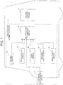
- a vehicle 1 is mounted with a self-position estimation device 2 and a driving support system 3.
- the self-position estimation device 2 includes an imaging device 10, a distance measurement device 11, a wheel speed sensor 12, a steering angle sensor 13, a gyro sensor 14, an acceleration sensor 15, and a self-position estimation circuit 16.
- the imaging device 10 is mounted in an inside of a vehicle cabin or the like of the vehicle 1, and captures an image of, for example, a region ahead of the vehicle 1.
- the imaging device 10 may be, for example, a wide-angle camera.
- the imaging device 10 outputs the captured image of the region ahead of the vehicle 1 to the self-position estimation circuit 16.
- the distance measurement device 11 is mounted to an outside of the vehicle cabin or the like of the vehicle 1, applies an electromagnetic wave to the region ahead of the vehicle 1, and detects a reflected wave therefrom.
- the distance measurement device 11 may be, for example, a laser range finder.
- a mounting position for the distance measurement device 11 may be, for example, around the bonnet, the bumper, the license plate, a headlight, or a side mirror of the vehicle 1.
- the distance measurement device 11 outputs a measurement result to the self-position estimation circuit 16.
- the wheel speed sensor 12 generates a preset number of wheel speed pulses every time each wheel of the vehicle 1 rotates one time.
- the wheel speed sensor 12 outputs the wheel speed pulses to the self-position estimation circuit 16.
- the steering angle sensor 13 is mounted, for example, onto a steering column configured to rotatably support a steering wheel of the vehicle 1.
- the steering angle sensor 13 detects a present steering angle that is a present rotation angle (a steering operation amount) of the steering wheel that is a steering operator.
- the steering angle sensor 13 outputs the detected present steering angle to the self-position estimation circuit 16.
- the gyro sensor 14 detects a yaw rate, a displacement amount in a pitch direction, and a displacement amount in a roll direction that are generated in the vehicle 1.
- the gyro sensor 14 outputs the detected yaw rate, displacement amount in the pitch direction, and displacement amount in the roll direction to the self-position estimation circuit 16.
- the acceleration sensor 15 detects a lateral G that is an acceleration/deceleration in a vehicle widthwise direction and an acceleration/deceleration in a front-rear direction that are generated in the vehicle 1.
- the acceleration sensor 15 outputs the detected lateral G and the detected acceleration/deceleration in the front-rear direction to the self-position estimation circuit 16.
- the self-position estimation circuit 16 is an electronic circuit device including a processor such as a central processing unit (CPU), a storage device, and peripheral components.
- a processor such as a central processing unit (CPU), a storage device, and peripheral components.
- the self-position estimation circuit 16 estimates a present position of the vehicle 1 on a map on the basis of signals received from the imaging device 10, the distance measurement device 11, the wheel speed sensor 12, the steering angle sensor 13, and the gyro sensor 14 and two-dimensional map information indicating a position of a known target on a two-dimensional map.
- the present position of the vehicle 1 on the map may be referred to as "self-position” .
- the self-position estimation circuit 16 outputs a self-position signal indicating the self-position to the driving support system 3.
- the driving support system 3 performs driving support for driving of the vehicle 1 by a driver by using the self-position indicated by the self-position signal received from the self-position estimation circuit 16.
- the driving support may be, for example, provision of information such as an alarm to the driver.
- the driving support system 3 may control at least one of the type and intensity of the alarm to be issued to the driver in accordance with the self-position of the vehicle 1.
- One example of the driving support may be control of a traveling state of the vehicle 1 including at least one of braking control, acceleration control, and steering control of the vehicle 1.
- the driving support system 3 may determine whether to generate braking force or driving force in the vehicle 1 in accordance with the self-position of the vehicle 1.
- the self-position estimation circuit 16 includes a target position detection unit 20, a movement amount estimation unit 21, a slope detection unit 22, a target position accumulation unit 23, a storage device 24, a selection unit 25, a position estimation unit 26, and a map information acquisition unit 27.
- the processor included in the self-position estimation circuit 16 executes a computer program stored in the storage device 24 to achieve functions of the target position detection unit 20, the movement amount estimation unit 21, the slope detection unit 22, the target position accumulation unit 23, the selection unit 25, the position estimation unit 26, and the map information acquisition unit 27.
- the target position detection unit 20 receives the captured image of the region ahead of the vehicle 1 produced by the imaging device 10. Additionally, the target position detection unit 20 receives the measurement result of the distance measurement device 11.
- the target position detection unit 20 detects each target existing around the vehicle 1 on the basis of the captured image of the region ahead of the vehicle 1 and the measurement result of the distance measurement device 11. For example, the target position detection unit 20 detects each target existing ahead of the vehicle 1.
- the target position detection unit 20 detects a relative position of each target relative to the vehicle 1.
- the target position detection unit 20 outputs a relative position signal indicating the detected relative position to the target position accumulation unit 23.
- the target may be, for example, a line (such as a lane marking) on a traveling road surface where the vehicle 1 is traveling, a curb of a road shoulder, a guardrail, or the like.
- the movement amount estimation unit 21 receives the wheel speed pulses, the present steering angle, and the yaw rate, respectively, from the wheel speed sensor 12, the steering angle sensor 13, and the gyro sensor 14. On the basis of the signals received from the wheel speed sensor 12, the steering angle sensor 13, and the gyro sensor 14, the movement amount estimation unit 21 estimates, by odometry, a movement amount ⁇ P of the vehicle 1 up to the present from the time point when the self-position of the vehicle 1 is estimated in a previous processing cycle. The movement amount estimation unit 21 outputs a movement amount signal indicating the estimated movement amount ⁇ P to the target position accumulation unit 23.
- the slope detection unit 22 receives the displacement amount in the pitch direction from the gyro sensor 14.
- the slope detection unit 22 On the basis of the displacement amount in the pitch direction received from the gyro sensor 14, the slope detection unit 22 detects a slope amount of a traveling road of the vehicle 1, i.e., an inclination of a direction in which the vehicle 1 is traveling.
- the slope detection unit 22 may receive the captured image of the region head of the vehicle 1 produced by the imaging device 10.
- the slope detection unit 22 may detect the slope amount of the traveling road of the vehicle 1 on the basis of a 3D point group flow by analyzing the captured image.
- the slope detection unit 22 determines whether or not the traveling road of the vehicle 1 is a slope section. For example, when the slope amount of the traveling road of the vehicle 1 is equal to or more than a predetermined threshold value, the slope detection unit 22 may determine that the traveling road is a slope section. The slope detection unit 22 outputs a determination result signal indicating the determination result to the selection unit 25.
- the target position accumulation unit 23 receives the relative position signal from the target position detection unit 20, and receives the movement amount signal from the movement amount estimation unit 21.
- the target position accumulation unit 23 accumulates the relative position of the target around the vehicle 1 indicated by the relative position signal in the storage device 24.
- the target position accumulation unit 23 corrects a relative position of the target accumulated in the past to a relative position relative to the present position of the vehicle 1 by using an elapsed time up to the present and the movement amount ⁇ P indicated by the movement amount signal. In other words, the target position accumulation unit 23 moves the relative position in a direction opposite to the moving direction of the vehicle 1 by the movement amount ⁇ P in which the vehicle has moved during the elapsed time up to the present.
- the target position accumulation unit 23 accumulates data of a target position (which may be hereinafter referred to as "target position data”) that is the corrected relative position in the storage device 24.
- the target position accumulation unit 23 updates the accumulated target position data by using the movement amount ⁇ P indicated by the movement amount signal. In other words, the target position accumulation unit 23 moves the relative position of the accumulated target position data in the direction opposite to the moving direction of the vehicle 1 by the movement amount ⁇ P. Then, the target position accumulation unit 23 overwrites the relative position relatively moved by the movement amount ⁇ P on the accumulated target position data.
- the selection unit 25 selects target position data to be used for estimation of the self-position of the vehicle 1 from among the target position data accumulated in the storage device 24.
- the target position data to be selected for use in estimation of the self-position may be hereinafter referred to as "selected target position data"
- the position estimation unit 26 collates the selected target position data with two-dimensional map information acquired by the map information acquisition unit 27 to estimate the self-position of the vehicle 1.
- the map information acquisition unit 27 acquires map data and the two-dimensional map information that indicates a position on a two-dimensional map of each target existing on the map data.
- the map information acquisition unit 27 is a car navigation system, a map database, or the like.
- the map information acquisition unit 27 may acquire the two-dimensional map information from outside via a communication system such as wireless communication (road-to-vehicle communication or vehicle-to-vehicle communication is also possible). In this case, the map information acquisition unit 27 may periodically acquire latest two-dimensional map information to update the possessed two-dimensional map information. Additionally, the map information acquisition unit 27 may accumulate, as two-dimensional map information, positional information of targets detected on a traveling road where the vehicle 1 actually traveled.
- the position estimation unit 26 may estimate the self-position of the vehicle 1 by collating the selected target position data with the two-dimensional map information, for example, by data collation processing as below.
- Reference sign S i denotes selected target position data.
- Index i is an integer of from 1 to N, and N is the number of pieces of the selected target position data.
- the position estimation unit 26 determines a tentative position of the vehicle 1 by correcting the self-position estimated in the previous processing cycle by the movement amount ⁇ P.
- the position estimation unit 26 assumes that the position on the two-dimensional map of the vehicle 1 is the tentative position, and converts the relative position of the target indicated by the selected target position data Si to an absolute position on the two-dimensional map.
- the position estimation unit 26 selects positional information M j of the target in the two-dimensional map information closest to the absolute position of the selected target position data S i .
- positional information M x is closest to selected target position data S 1
- positional information M y is closest to selected target position data S 2
- positional information M z is closest to selected target position data S 3 .
- the position estimation unit 26 calculates a position and a posture of the vehicle 1 having a minimum average S by numerical analysis, and determines as estimated values for the self-position of the vehicle 1.
- the position estimation unit 26 outputs the estimated values for the self-position to the driving support system 3.
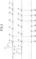
- the distance between the vehicle 1 and a target indicated by the target position data of the target detected before passing through the slope section may be longer than an actual horizontal distance. The reason for that will be described with reference to FIG. 4 .
- the upper stage is a schematic diagram illustrating a traveling road of the vehicle 1 including a slope section Ss and targets on the traveling road.
- Square plots T1 to T7 represent the targets on the traveling road.
- the position of the vehicle 1 in FIG. 4 indicates a position at a time point after having passed through the slope section.
- the middle stage is a schematic diagram illustrating a distance between the vehicle 1 and each target indicated by target position data accumulated in the storage device 24 at the time point after having passed through the slope section.
- Circular plots S1 to S7 correspond to pieces of the target position data of the targets T1 to T7.
- the lower stage is a schematic diagram illustrating a distance between each of the targets T1 to T7 and the vehicle 1 on a two-dimensional map.
- Triangular plots M1 to M7 represent positions of the targets T1 to T7 on the map.
- the oblique distance is longer than the horizontal distance. Due to this, the target position data of the targets T1 to T7 accumulated in the past are corrected at the position of the vehicle 1 at the time point after having passed through the slope section in FIG. 4 by using the movement amount ⁇ P including a movement amount in the slope section Ss.
- distances between the vehicle 1 and the targets indicated by the target position data S3 to S7 of the targets T3 to T7 in a section before passing through the slope section Ss are longer than distances on the two-dimensional map (i.e., the horizontal distances).
- differences between distances between the vehicle 1 and the targets T3 and T4 indicated by the pieces of the target position data S3 and S4 and distances on the two-dimensional map are e3 and e4, respectively, in which e4 is longer than e3.
- relative positions of the targets T5 to T7 indicated by the pieces of the target position data S5 to S7 are all similarly shifted backward by a difference e5 between the oblique distance and the horizontal distance in the slope section Ss. Additionally, the relative positions between the pieces of the target position data S5 to S7 do not change.
- the pieces of the target position data S1 to S2 of the targets T1 to T2 in a flat section after having passed through the slope section Ss are not corrected by using the movement amount ⁇ P estimated in the slope section Ss.
- the pieces of the target position data S1 to S2 of the targets T1 to T2 in a flat section after having passed through the slope section Ss are not corrected by using the movement amount ⁇ P estimated in the slope section Ss.
- the pieces of the target position data S1 to S7 are collated with the two-dimensional map information, the pieces of the target position data S1 to S2 in the flat section after having passed through the slope section, where the relative position between the targets does not change, and the pieces of the target position data S5 to S7 in the flat section before entering the slope section, where the relative position between the targets does not change, match well with position information on the map.
- the target position data before entering the slope section Ss are larger in amount than the target position data after having passed through the slope section Ss.
- the target position data before entering the slope section Ss dominantly influence, which may make an estimation error large.
- the estimation error becomes large in estimating the self-position by using targets around the intersection, such as a stop line.
- error in the estimated position for the self-position may be fluctuated and unstable.
- FIG. 5 illustrates the situation.
- Reference sign P1 denotes the estimated position calculated by the dominant influence of the target position data S1 to S2 after having passed through the slope section
- reference sign P2 denotes the estimated position calculated by the dominant influence of the target position data S5 to S7 before entering the slope section.
- calculation result may waver unstably between the P1 and the P2.
- the selection unit 25 determines whether or not the vehicle 1 has passed the slope section Ss on the basis of the determination result signal from the slope detection unit 22.
- the selection unit 25 selects, as the selected target position data, the target position data S1 to S2 after having passed through the slope section (i.e., the target position data of the targets in the section up to the present position after having passed through the slope section). In other words, the selection unit 25 excludes the target position data S3 to S7 before passing through the slope section from the selected target position data.
- the position estimation unit 26 collates the selected target position data S1 to S2 after having passed through the slope section with the positions M1 to M2 of the targets T1 to T2 on the map to estimate the self-position of the vehicle 1.
- FIG. 6 illustrates this situation.
- the target position data S3 to S7 of the targets detected before passing through the slope section Ss by traveling of the vehicle 1 in the slope section Ss is longer than the actual horizontal distance
- the target position data S3 to S7 can be excluded from position estimation. This can suppress reduction in accuracy of position estimation on the two-dimensional map due to the difference between the oblique distance and the horizontal distance in the slope section.
- the selection unit 25 may delete the target position data other than the selected target position data (i.e., the target position data before passing through the slope section) from the storage device 24.
- the selection unit 25 may delete the target position data S3 to S4 in the slope section and the target position data S5 to S7 before entering the slope section from the storage device 24 .
- the position estimation unit 26 may estimate the present position of the vehicle 1 by collating the target position data left in the storage device 24 with the map information indicating the positions of the targets on the map.
- the storage region of the storage device 24 can be effectively utilized.
- the selection unit 25 may preferentially select, as the selected target position data, the target position data of a target detected by the target position detection unit 20 after having passed through the slope section, whose an elapsed time from the detection of the target is shorter.
- the selection unit 25 may select the target detection data of one or more targets around the present position of the vehicle 1 after having passed through the slope section.
- the selection unit 25 selects the target position data of targets existing within about 20 m from the present position of the vehicle 1.
- the target position data of one or more targets around the present position of the vehicle 1 tend to have high position accuracy, because there is little accumulation of errors due to correction using the movement amount ⁇ P.
- the positional data of a lane and/or a curb, which are road boundaries are highly accurate in terms of a lateral position within a traveling road.
- the imaging device 10, the distance measurement device 11, and the target position detection unit 20 detect the relative position of each target existing around the vehicle 1 relative to the vehicle 1.
- the target position detection unit 20 outputs a relative position signal indicating the detected relative position to the target position accumulation unit 23.
- the movement amount estimation unit 21 estimates the movement amount ⁇ P of the vehicle 1 up to the present from the time point when the self-position of the vehicle 1 is estimated in the previous processing cycle.
- the target position accumulation unit 23 accumulates the relative position of the each target around the vehicle 1 indicated by the relative position signal in the storage device 24. Additionally, the target portion accumulation unit 23 corrects the relative position of the target accumulated in the past to a relative position relative to the present position of the vehicle 1 by using an elapsed time up to the present and the movement amount ⁇ P indicated by the movement amount signal, and accumulates as target position data in the storage device 24.
- the imaging device 10, the gyro sensor 14, and the slope detection unit 22 detect a slope amount of the traveling road of the vehicle 1.
- step S5 the slope detection unit 22 and the selection unit 25 determine whether the vehicle 1 is in a slope section, has not yet entered the slope section, or has passed through the slope section by slope section passage determination processing.
- step S6 the selection unit 25 determines whether or not it has been determined that the vehicle 1 is in the slope section by the slope section passage determination processing.
- step S6: Y the processing goes to step S9.
- step S6: N the processing goes to step S7.
- step S7 the selection unit 25 determines whether or not it has been determined that the vehicle 1 has passed through the slope section by the slope section passage determination processing.
- step S7: Y the processing goes to step S8.
- step S7: N When the vehicle 1 has not yet passed through the slope section (step S7: N), i.e., when the vehicle 1 has not yet entered the slope section, the processing goes to step S9.
- the selection unit 25 deletes the target position data S3 to S7 before passing through the slope section from the storage device 24. In other words, the selection unit 25 selects the target position data S1 to S2 after having passed through the slope section, and leaves it as the selected target position data in the storage device 24.
- the position estimation unit 26 collates the selected target position data with map information to estimate the self-position of the vehicle 1.
- the position estimation unit 26 estimates the present position of the vehicle 1 by collating the target position data left in the storage device 24 with map information.
- the driving support system 3 uses the self-position of the vehicle 1 estimated by the position estimation unit 26 to perform driving support for driving of the vehicle 1 by a driver.
- step S20 the selection unit 25 determines whether or not it has been determined that the vehicle 1 is in the slope section by the previous slope section passage determination processing. When it has been determined that the vehicle 1 is in the slope section (step S20: Y), the processing goes to step S24. When it has not been determined that the vehicle 1 is in the slope section (step S20: N), the processing goes to step S21.
- the slope detection unit 22 determines whether or not the slope amount of the traveling road of the vehicle 1 is equal to or more than a threshold value.
- the threshold value may be set in accordance with whether or not the difference between the oblique distance and the horizontal distance due to the slope is within an allowable range .
- the threshold value may be, for example, two degrees .
- the selection unit 25 determines that the vehicle 1 has not yet entered the slope section. Then, the processing is ended.
- the slope detection unit 22 determines that the vehicle 1 is in the slope section. Then, the processing is ended.
- step S24 the slope detection unit 22 determines whether or not the slope amount of the traveling road of the vehicle 1 is equal to or more than the threshold value.
- step S24: Y the processing goes to step S23.
- step S24: N the processing goes to step S25.
- the selection unit 25 determines that the vehicle 1 has already passed through the slope section. Then, the processing is ended.
- the selection unit 25 may preferentially select, as the selected target position data, target position data of any of the targets after having passed through a slope section, and may exclude the rest thereof from the selected target position data.
- the selection unit 25 may preferentially select, as the selected target position data, a target(s) whose angle between a straight line connecting the vehicle 1 and the target and a traveling direction of the vehicle 1 becomes larger.
- the selection unit 25 may exclude, from the selected target position data, a target (s) whose distance from the vehicle 1 is longer than a predetermined upper limit.
- a target (s) whose distance from the vehicle 1 is longer than a predetermined upper limit.
- the upper limit of the distance between the target (s) and the vehicle 1 may be adjusted in accordance with an allowable range of a position estimation error due to the estimation error of the movement amount ⁇ P.
- the self-position of the vehicle 1 can be detected with high accuracy in each of a first section having a slope amount less than the threshold value in which the vehicle 1 traveled before entering the slope section and a second section having a slope amount less than the threshold value in which the vehicle 1 travels after passing through the slope section.
- a relative position between the self-position of the vehicle 1 estimated in the first section and the self-position of the vehicle 1 estimated in the second section can be calculated with high accuracy.
- correction can be made by using the relative position between the self -positions estimated in the first and second sections.
- the self-position estimation circuit 16 of the second embodiment corrects the target position data of the each target in the first section by using the relative position between the self-position estimated in the first section and the self-position estimated in the second section.
- the self-position estimation circuit 16 includes a correction unit 28.
- the processor included in the self-position estimation circuit 16 executes a computer program stored in the storage device 24 to achieve function of the correction unit 28.
- the position estimation unit 26 collates the target position data of the targets in the first section with the map information to estimate a first position of the vehicle 1 before entering the slope section.
- the position estimation unit 26 outputs the first position to the driving support system 3 and the correction unit 28.
- the correction unit 28 adds information of the first position of the vehicle 1 estimated in the first section to the target position data of the targets in the first section, and stores in the storage device 24.
- the position estimation unit 26 collates the target position data of the targets in the second section with the map information to estimate a second position of the vehicle 1 after having passed through the slope section.
- the position estimation unit 26 outputs the second position to the correction unit 28.
- the correction unit 28 corrects the target position data of the targets in the first section on the basis of a relative position between the first position and the second position.
- the position estimation unit 26 collates the corrected target position data and the target position data of targets in the second section with the map information to estimate a second position of the vehicle 1 after having passed through the slope section.
- the position estimation unit 26 outputs the second position estimated after the correction of the target position data to the driving support system 3.
- the object position estimation unit 26 adds information of the second position estimated after the correction of the target position data to the target position data of the targets in the second section, and stores in the storage device 24.
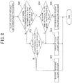
- Pieces of processing of steps S30 to S34 are the same as those of steps S1 to S5 of FIG. 7 .
- step S35 the selection unit 25 determines whether or not it has been determined by slope section passing determination processing that the vehicle 1 is in the slope section.
- step S35: Y the processing goes to step S43.
- step S36 the processing goes to step S36.
- step S36 the selection unit 25 determines whether or not it has been determined by the slope section passing determination processing that the vehicle 1 has passed through the slope section.
- step S36: Y the processing goes to step S37.
- step S36: N When the vehicle 1 has not yet passed through the slope section (step S36: N), i.e., when the vehicle 1 has not yet entered the slope section, the processing goes to step S43.
- the selection unit 25 deletes the target position data of targets in the slope section from the storage device 24.
- the selection unit 25 selects, as the selected target position data, the target position data of targets other than those in the slope section (i.e., the target position data of targets before entering the slope section and targets after having passed through the slope section).
- the selection unit 25 selects, as the selected target position data, the target position data of targets in the sections having a slope amount less than the threshold value, which are sections other than the slope section, without limiting to the target position data of the targets after having passed through the slope section. Note that it is unnecessary to select all the targets other than those in the slope section as the selected target position data. Only target position data necessary to enable estimation of the self-position of the vehicle 1 by collating with the map information acquired by the map information acquisition unit 27 may be selected.
- the selection unit 25 selects the target position data of the targets in the second section after having passed through the slope section.
- the position estimation unit 26 collates the target position data selected at step S38 with two-dimensional map information to estimate the second position of the vehicle 1.
- the correction unit 28 reads out, from the storage device 24, the information of the first position of the vehicle 1 estimated in the first section and stored in addition to the target position data of the targets in the first section before entering the slope section.
- the correction unit 28 corrects the target position data of the targets in the first section on the basis of a relative position between the first position and the second position.
- the position estimation unit 26 collates the target position data left in the storage device 24 (i.e., the target position data corrected at step S40 and the target position data of the targets in the second section) with the map information to estimate the second position of the vehicle 1 after having passed through the slope section.
- the correction unit 28 adds information of the second position of the vehicle 1 estimated at step S41 to the target position of the targets in the second section, and stores in the storage device 24.
- step S42 Processing of step S42 is the same as the processing of step S10 of FIG. 7 .
- step S43 Processing of step S43 is the same as the processing of step S9 of FIG. 7 . After step S43, the processing goes to step S42.
- the position estimation unit 26 collates the target position data of the targets in the first section having a slope amount less than the threshold value with map information before entering the slope section to estimate the first position of the vehicle 1 before entering the slope section. Additionally, the position estimation unit 26 collates the target position data of the targets in the second section having a slope amount less than the threshold value with map information after having passed through the slope section to estimate the second position of the vehicle 1 after having passed through the slope section.
- the correction unit 28 corrects the target position data of the targets in the first section on the basis of the relative position between the first position and the second position.
- the position estimation unit 26 collates the corrected target position data and the target position data of the targets in the second section with the map information to estimate the self-position of the vehicle 1.
- the position estimation unit 26 collates, without limiting to the target position data of the targets in the second section after having passed through the slope section, the target position data of the targets in the sections having a slope amount less than the threshold value with the map information to estimate the self-position of the vehicle 1.
- the target position data of targets existing in the undulations do not have to be excluded from the selected target position data.
- the selection unit 25 may exclude, from the selected target position data, the target position data of targets in a slope section such as an entrance of a bridge or a highway, and does not have to exclude, from the selected target position data, for example, the target position data of targets existing in undulations having a slope amount of from 1 to 2 degrees and taking about from 2 to 3 seconds to pass through.
- the selection unit 25 may select also the target position data of targets in the section as the selected target position data.
- the selection unit 25 may exclude the target position data of targets in the section from the selected target position data. In other words, the selection unit 25 selects, as the selected target position data, the target position data of targets in a section other than such a section, that have a slope less than the threshold value. The same applies to the first embodiment.
- the selection unit 25 selects the target position data of targets in a section other than such a section, so that the target position data in the slope section that influence accuracy of the estimation of the self-position can be appropriately excluded.
- the predetermined length may be set on the basis of a traveling time during which the vehicle 1 travels, for example, in a section having a slope equal to or more than the threshold value.
- the predetermined length may be set to a length of 3 seconds or longer.
- the predetermined length may be set on the basis of the distance of a section having a slope equal to or more than the threshold value.
- the predetermined length may be set to a length of 30 seconds or longer.
- the predetermined length may be dynamically set to become shorter as the slope amount of the traveling road of the vehicle 1 becomes larger. This can suppress a measurement error due to the difference between the oblique distance and the horizontal distance to within a desired allowable range, regardless of the magnitude of the slope amount.
Landscapes
- Engineering & Computer Science (AREA)
- Radar, Positioning & Navigation (AREA)
- Remote Sensing (AREA)
- Physics & Mathematics (AREA)
- General Physics & Mathematics (AREA)
- Automation & Control Theory (AREA)
- Electromagnetism (AREA)
- Computer Vision & Pattern Recognition (AREA)
- Multimedia (AREA)
- Computer Networks & Wireless Communication (AREA)
- Aviation & Aerospace Engineering (AREA)
- Theoretical Computer Science (AREA)
- Optics & Photonics (AREA)
- Navigation (AREA)
- Traffic Control Systems (AREA)
- Control Of Position, Course, Altitude, Or Attitude Of Moving Bodies (AREA)
Applications Claiming Priority (1)
| Application Number | Priority Date | Filing Date | Title |
|---|---|---|---|
| PCT/JP2016/071922 WO2018020589A1 (ja) | 2016-07-26 | 2016-07-26 | 自己位置推定方法及び自己位置推定装置 |
Publications (3)
| Publication Number | Publication Date |
|---|---|
| EP3492871A1 true EP3492871A1 (de) | 2019-06-05 |
| EP3492871A4 EP3492871A4 (de) | 2019-09-04 |
| EP3492871B1 EP3492871B1 (de) | 2020-05-06 |
Family
ID=61016515
Family Applications (1)
| Application Number | Title | Priority Date | Filing Date |
|---|---|---|---|
| EP16910492.4A Active EP3492871B1 (de) | 2016-07-26 | 2016-07-26 | Eigenpositionschätzungsverfahren und eigenpositionschätzungsvorrichtung |
Country Status (10)
| Country | Link |
|---|---|
| US (1) | US11243080B2 (de) |
| EP (1) | EP3492871B1 (de) |
| JP (1) | JP6575686B2 (de) |
| KR (1) | KR20190028528A (de) |
| CN (1) | CN109564098B (de) |
| BR (1) | BR112019001441B1 (de) |
| CA (1) | CA3032068C (de) |
| MX (1) | MX2019001092A (de) |
| RU (1) | RU2722356C1 (de) |
| WO (1) | WO2018020589A1 (de) |
Families Citing this family (11)
| Publication number | Priority date | Publication date | Assignee | Title |
|---|---|---|---|---|
| WO2018020588A1 (ja) * | 2016-07-26 | 2018-02-01 | 日産自動車株式会社 | 自己位置推定方法及び自己位置推定装置 |
| JP7137359B2 (ja) * | 2018-05-30 | 2022-09-14 | フォルシアクラリオン・エレクトロニクス株式会社 | 情報処理装置 |
| JP7084792B2 (ja) * | 2018-06-18 | 2022-06-15 | 日産自動車株式会社 | 走行軌跡推定方法及び走行軌跡推定装置 |
| CN111480131B (zh) * | 2018-08-23 | 2024-01-12 | 日本精工株式会社 | 自行装置、自行装置的行进控制方法以及行进控制程序 |
| CN109215136B (zh) | 2018-09-07 | 2020-03-20 | 百度在线网络技术(北京)有限公司 | 一种真实数据增强方法、装置以及终端 |
| CN109146898B (zh) * | 2018-09-07 | 2020-07-24 | 百度在线网络技术(北京)有限公司 | 一种仿真数据量增强方法、装置以及终端 |
| CN110103823B (zh) * | 2019-05-21 | 2021-06-11 | 东南大学 | 一种基于增强型数字地图的车辆侧翻事前预警方法 |
| CN110473417A (zh) * | 2019-06-03 | 2019-11-19 | 浙江吉利控股集团有限公司 | 一种高架桥限速值提示方法、装置及存储介质 |
| JP7358108B2 (ja) | 2019-07-31 | 2023-10-10 | キヤノン株式会社 | 情報処理装置、情報処理方法及びプログラム |
| JP7332403B2 (ja) * | 2019-09-11 | 2023-08-23 | 株式会社東芝 | 位置推定装置、移動体制御システム、位置推定方法およびプログラム |
| CN113450407B (zh) * | 2021-05-14 | 2023-10-13 | 东莞市李群自动化技术有限公司 | 定位方法及作业方法、电子设备、轨道设备和存储介质 |
Family Cites Families (22)
| Publication number | Priority date | Publication date | Assignee | Title |
|---|---|---|---|---|
| US5367458A (en) * | 1993-08-10 | 1994-11-22 | Caterpillar Industrial Inc. | Apparatus and method for identifying scanned reflective anonymous targets |
| JP3626733B2 (ja) * | 2002-03-01 | 2005-03-09 | 三菱電機株式会社 | 車線認識画像処理装置及びその処理を実行させるためのプログラム |
| JP4092308B2 (ja) * | 2004-06-02 | 2008-05-28 | トヨタ自動車株式会社 | 境界線検出装置 |
| JP2008250906A (ja) | 2007-03-30 | 2008-10-16 | Sogo Keibi Hosho Co Ltd | 移動ロボット、自己位置補正方法および自己位置補正プログラム |
| CN101952688A (zh) * | 2008-02-04 | 2011-01-19 | 电子地图北美公司 | 用于与传感器检测到的对象进行地图匹配的方法 |
| JP2010146202A (ja) * | 2008-12-17 | 2010-07-01 | Toyota Central R&D Labs Inc | 移動体と移動体の位置推定方法 |
| JP5441549B2 (ja) * | 2009-07-29 | 2014-03-12 | 日立オートモティブシステムズ株式会社 | 道路形状認識装置 |
| JP5278378B2 (ja) * | 2009-07-30 | 2013-09-04 | 日産自動車株式会社 | 車両運転支援装置及び車両運転支援方法 |
| JP5321497B2 (ja) * | 2010-02-22 | 2013-10-23 | 株式会社デンソー | 白線認識装置 |
| KR20110134633A (ko) | 2010-06-09 | 2011-12-15 | 엠텍비젼 주식회사 | 속도 측정 장치 및 측정된 속도 보정 방법 |
| JP5206740B2 (ja) * | 2010-06-23 | 2013-06-12 | 株式会社デンソー | 道路形状検出装置 |
| JP2012103858A (ja) * | 2010-11-09 | 2012-05-31 | Toyota Motor Corp | 障害物認識装置 |
| JP5951266B2 (ja) * | 2012-01-27 | 2016-07-13 | 三菱重工業株式会社 | 勾配情報取得方法、勾配情報記憶済記憶媒体を作成する方法、勾配情報取得装置およびプログラム |
| WO2014076844A1 (ja) * | 2012-11-19 | 2014-05-22 | 株式会社日立製作所 | 自律移動システムおよび管制装置 |
| JP5962771B2 (ja) * | 2012-12-12 | 2016-08-03 | 日産自動車株式会社 | 移動物体位置姿勢角推定装置及び移動物体位置姿勢角推定方法 |
| JP5949955B2 (ja) * | 2013-01-25 | 2016-07-13 | トヨタ自動車株式会社 | 道路環境認識システム |
| MX349024B (es) * | 2014-02-24 | 2017-07-07 | Nissan Motor | Dispositivo de calculo de la ubicacion propia y metodo de calculo de la ubicacion propia. |
| JP6379751B2 (ja) * | 2014-07-04 | 2018-08-29 | 日産自動車株式会社 | 走行支援装置及び走行支援方法 |
| WO2017056484A1 (ja) * | 2015-09-28 | 2017-04-06 | 京セラ株式会社 | 画像処理装置、ステレオカメラ装置、車両及び画像処理方法 |
| JP6406226B2 (ja) * | 2015-11-27 | 2018-10-17 | 株式会社デンソー | 車両制御装置 |
| US10184799B2 (en) * | 2016-06-13 | 2019-01-22 | The Boeing Company | Systems and methods for targeting objects of interest in denied GPS environments |
| GB2552021B (en) * | 2016-07-08 | 2019-08-28 | Jaguar Land Rover Ltd | Improvements in vehicle speed control |
-
2016
- 2016-07-26 US US16/320,307 patent/US11243080B2/en active Active
- 2016-07-26 EP EP16910492.4A patent/EP3492871B1/de active Active
- 2016-07-26 MX MX2019001092A patent/MX2019001092A/es active IP Right Grant
- 2016-07-26 CN CN201680087942.5A patent/CN109564098B/zh active Active
- 2016-07-26 CA CA3032068A patent/CA3032068C/en active Active
- 2016-07-26 JP JP2018530245A patent/JP6575686B2/ja active Active
- 2016-07-26 RU RU2019105128A patent/RU2722356C1/ru active
- 2016-07-26 BR BR112019001441-1A patent/BR112019001441B1/pt active IP Right Grant
- 2016-07-26 WO PCT/JP2016/071922 patent/WO2018020589A1/ja unknown
- 2016-07-26 KR KR1020197004534A patent/KR20190028528A/ko active IP Right Grant
Also Published As
| Publication number | Publication date |
|---|---|
| US11243080B2 (en) | 2022-02-08 |
| CA3032068C (en) | 2020-01-14 |
| RU2722356C1 (ru) | 2020-05-29 |
| CN109564098B (zh) | 2020-07-14 |
| EP3492871A4 (de) | 2019-09-04 |
| US20190265040A1 (en) | 2019-08-29 |
| WO2018020589A1 (ja) | 2018-02-01 |
| BR112019001441A2 (pt) | 2019-05-07 |
| JPWO2018020589A1 (ja) | 2019-03-28 |
| KR20190028528A (ko) | 2019-03-18 |
| CA3032068A1 (en) | 2018-02-01 |
| EP3492871B1 (de) | 2020-05-06 |
| CN109564098A (zh) | 2019-04-02 |
| JP6575686B2 (ja) | 2019-09-18 |
| BR112019001441B1 (pt) | 2023-02-07 |
| MX2019001092A (es) | 2019-07-04 |
Similar Documents
| Publication | Publication Date | Title |
|---|---|---|
| EP3492871B1 (de) | Eigenpositionschätzungsverfahren und eigenpositionschätzungsvorrichtung | |
| US10625746B2 (en) | Self-position estimation method and self-position estimation device | |
| US10289120B2 (en) | Self-position estimation device and self-position estimation method | |
| US20180172455A1 (en) | Position Estimation Device and Position Estimation Method | |
| CN103534729A (zh) | 用于确定车辆的自身运动的方法和系统 | |
| JP2007309757A (ja) | 対象物認識装置 | |
| KR102441073B1 (ko) | 자이로 센싱값 보상 장치, 그를 포함한 시스템 및 그 방법 | |
| KR20190051786A (ko) | 자차 위치 추정 장치 | |
| KR20190104360A (ko) | 주행 이력의 기억 방법, 주행 궤적 모델의 생성 방법, 자기 위치 추정 방법, 및 주행 이력의 기억 장치 | |
| US11608059B2 (en) | Method and apparatus for method for real time lateral control and steering actuation assessment | |
| JP6747157B2 (ja) | 自己位置推定方法及び自己位置推定装置 | |
| KR101980509B1 (ko) | 차간 거리 추정 방법 및 차간 거리 추정 장치 | |
| CN113795726B (zh) | 自身位置修正方法及自身位置修正装置 | |
| RU2781373C1 (ru) | Способ коррекции собственного местоположения и устройство коррекции собственного местоположения | |
| JP2023083942A (ja) | 位置精度判定装置、位置精度判定用コンピュータプログラム及び位置精度判定方法 |
Legal Events
| Date | Code | Title | Description |
|---|---|---|---|
| STAA | Information on the status of an ep patent application or granted ep patent |
Free format text: STATUS: THE INTERNATIONAL PUBLICATION HAS BEEN MADE |
|
| PUAI | Public reference made under article 153(3) epc to a published international application that has entered the european phase |
Free format text: ORIGINAL CODE: 0009012 |
|
| STAA | Information on the status of an ep patent application or granted ep patent |
Free format text: STATUS: REQUEST FOR EXAMINATION WAS MADE |
|
| 17P | Request for examination filed |
Effective date: 20190225 |
|
| AK | Designated contracting states |
Kind code of ref document: A1 Designated state(s): AL AT BE BG CH CY CZ DE DK EE ES FI FR GB GR HR HU IE IS IT LI LT LU LV MC MK MT NL NO PL PT RO RS SE SI SK SM TR |
|
| AX | Request for extension of the european patent |
Extension state: BA ME |
|
| A4 | Supplementary search report drawn up and despatched |
Effective date: 20190801 |
|
| RIC1 | Information provided on ipc code assigned before grant |
Ipc: G06K 9/00 20060101ALI20190726BHEP Ipc: G05D 1/00 20060101ALI20190726BHEP Ipc: G01C 21/36 20060101ALI20190726BHEP Ipc: G01C 21/30 20060101AFI20190726BHEP Ipc: G08G 1/16 20060101ALI20190726BHEP Ipc: G01S 5/16 20060101ALI20190726BHEP Ipc: G05D 1/02 20060101ALI20190726BHEP |
|
| DAV | Request for validation of the european patent (deleted) | ||
| DAX | Request for extension of the european patent (deleted) | ||
| GRAP | Despatch of communication of intention to grant a patent |
Free format text: ORIGINAL CODE: EPIDOSNIGR1 |
|
| STAA | Information on the status of an ep patent application or granted ep patent |
Free format text: STATUS: GRANT OF PATENT IS INTENDED |
|
| RIN1 | Information on inventor provided before grant (corrected) |
Inventor name: TAKANO, HIROYUKI Inventor name: NANRI, TAKUYA Inventor name: TSUCHIYA, CHIKAO Inventor name: SANO, YASUHITO |
|
| INTG | Intention to grant announced |
Effective date: 20200204 |
|
| GRAS | Grant fee paid |
Free format text: ORIGINAL CODE: EPIDOSNIGR3 |
|
| GRAA | (expected) grant |
Free format text: ORIGINAL CODE: 0009210 |
|
| STAA | Information on the status of an ep patent application or granted ep patent |
Free format text: STATUS: THE PATENT HAS BEEN GRANTED |
|
| AK | Designated contracting states |
Kind code of ref document: B1 Designated state(s): AL AT BE BG CH CY CZ DE DK EE ES FI FR GB GR HR HU IE IS IT LI LT LU LV MC MK MT NL NO PL PT RO RS SE SI SK SM TR |
|
| REG | Reference to a national code |
Ref country code: GB Ref legal event code: FG4D |
|
| REG | Reference to a national code |
Ref country code: CH Ref legal event code: EP Ref country code: AT Ref legal event code: REF Ref document number: 1267481 Country of ref document: AT Kind code of ref document: T Effective date: 20200515 |
|
| REG | Reference to a national code |
Ref country code: IE Ref legal event code: FG4D |
|
| REG | Reference to a national code |
Ref country code: DE Ref legal event code: R096 Ref document number: 602016036233 Country of ref document: DE |
|
| REG | Reference to a national code |
Ref country code: LT Ref legal event code: MG4D |
|
| REG | Reference to a national code |
Ref country code: NL Ref legal event code: MP Effective date: 20200506 |
|
| PG25 | Lapsed in a contracting state [announced via postgrant information from national office to epo] |
Ref country code: LT Free format text: LAPSE BECAUSE OF FAILURE TO SUBMIT A TRANSLATION OF THE DESCRIPTION OR TO PAY THE FEE WITHIN THE PRESCRIBED TIME-LIMIT Effective date: 20200506 Ref country code: SE Free format text: LAPSE BECAUSE OF FAILURE TO SUBMIT A TRANSLATION OF THE DESCRIPTION OR TO PAY THE FEE WITHIN THE PRESCRIBED TIME-LIMIT Effective date: 20200506 Ref country code: NO Free format text: LAPSE BECAUSE OF FAILURE TO SUBMIT A TRANSLATION OF THE DESCRIPTION OR TO PAY THE FEE WITHIN THE PRESCRIBED TIME-LIMIT Effective date: 20200806 Ref country code: GR Free format text: LAPSE BECAUSE OF FAILURE TO SUBMIT A TRANSLATION OF THE DESCRIPTION OR TO PAY THE FEE WITHIN THE PRESCRIBED TIME-LIMIT Effective date: 20200807 Ref country code: IS Free format text: LAPSE BECAUSE OF FAILURE TO SUBMIT A TRANSLATION OF THE DESCRIPTION OR TO PAY THE FEE WITHIN THE PRESCRIBED TIME-LIMIT Effective date: 20200906 Ref country code: FI Free format text: LAPSE BECAUSE OF FAILURE TO SUBMIT A TRANSLATION OF THE DESCRIPTION OR TO PAY THE FEE WITHIN THE PRESCRIBED TIME-LIMIT Effective date: 20200506 Ref country code: PT Free format text: LAPSE BECAUSE OF FAILURE TO SUBMIT A TRANSLATION OF THE DESCRIPTION OR TO PAY THE FEE WITHIN THE PRESCRIBED TIME-LIMIT Effective date: 20200907 |
|
| PG25 | Lapsed in a contracting state [announced via postgrant information from national office to epo] |
Ref country code: LV Free format text: LAPSE BECAUSE OF FAILURE TO SUBMIT A TRANSLATION OF THE DESCRIPTION OR TO PAY THE FEE WITHIN THE PRESCRIBED TIME-LIMIT Effective date: 20200506 Ref country code: RS Free format text: LAPSE BECAUSE OF FAILURE TO SUBMIT A TRANSLATION OF THE DESCRIPTION OR TO PAY THE FEE WITHIN THE PRESCRIBED TIME-LIMIT Effective date: 20200506 Ref country code: HR Free format text: LAPSE BECAUSE OF FAILURE TO SUBMIT A TRANSLATION OF THE DESCRIPTION OR TO PAY THE FEE WITHIN THE PRESCRIBED TIME-LIMIT Effective date: 20200506 Ref country code: BG Free format text: LAPSE BECAUSE OF FAILURE TO SUBMIT A TRANSLATION OF THE DESCRIPTION OR TO PAY THE FEE WITHIN THE PRESCRIBED TIME-LIMIT Effective date: 20200806 |
|
| REG | Reference to a national code |
Ref country code: AT Ref legal event code: MK05 Ref document number: 1267481 Country of ref document: AT Kind code of ref document: T Effective date: 20200506 |
|
| PG25 | Lapsed in a contracting state [announced via postgrant information from national office to epo] |
Ref country code: AL Free format text: LAPSE BECAUSE OF FAILURE TO SUBMIT A TRANSLATION OF THE DESCRIPTION OR TO PAY THE FEE WITHIN THE PRESCRIBED TIME-LIMIT Effective date: 20200506 Ref country code: NL Free format text: LAPSE BECAUSE OF FAILURE TO SUBMIT A TRANSLATION OF THE DESCRIPTION OR TO PAY THE FEE WITHIN THE PRESCRIBED TIME-LIMIT Effective date: 20200506 |
|
| PG25 | Lapsed in a contracting state [announced via postgrant information from national office to epo] |
Ref country code: RO Free format text: LAPSE BECAUSE OF FAILURE TO SUBMIT A TRANSLATION OF THE DESCRIPTION OR TO PAY THE FEE WITHIN THE PRESCRIBED TIME-LIMIT Effective date: 20200506 Ref country code: CZ Free format text: LAPSE BECAUSE OF FAILURE TO SUBMIT A TRANSLATION OF THE DESCRIPTION OR TO PAY THE FEE WITHIN THE PRESCRIBED TIME-LIMIT Effective date: 20200506 Ref country code: ES Free format text: LAPSE BECAUSE OF FAILURE TO SUBMIT A TRANSLATION OF THE DESCRIPTION OR TO PAY THE FEE WITHIN THE PRESCRIBED TIME-LIMIT Effective date: 20200506 Ref country code: DK Free format text: LAPSE BECAUSE OF FAILURE TO SUBMIT A TRANSLATION OF THE DESCRIPTION OR TO PAY THE FEE WITHIN THE PRESCRIBED TIME-LIMIT Effective date: 20200506 Ref country code: SM Free format text: LAPSE BECAUSE OF FAILURE TO SUBMIT A TRANSLATION OF THE DESCRIPTION OR TO PAY THE FEE WITHIN THE PRESCRIBED TIME-LIMIT Effective date: 20200506 Ref country code: IT Free format text: LAPSE BECAUSE OF FAILURE TO SUBMIT A TRANSLATION OF THE DESCRIPTION OR TO PAY THE FEE WITHIN THE PRESCRIBED TIME-LIMIT Effective date: 20200506 Ref country code: EE Free format text: LAPSE BECAUSE OF FAILURE TO SUBMIT A TRANSLATION OF THE DESCRIPTION OR TO PAY THE FEE WITHIN THE PRESCRIBED TIME-LIMIT Effective date: 20200506 Ref country code: AT Free format text: LAPSE BECAUSE OF FAILURE TO SUBMIT A TRANSLATION OF THE DESCRIPTION OR TO PAY THE FEE WITHIN THE PRESCRIBED TIME-LIMIT Effective date: 20200506 |
|
| REG | Reference to a national code |
Ref country code: DE Ref legal event code: R097 Ref document number: 602016036233 Country of ref document: DE |
|
| PG25 | Lapsed in a contracting state [announced via postgrant information from national office to epo] |
Ref country code: PL Free format text: LAPSE BECAUSE OF FAILURE TO SUBMIT A TRANSLATION OF THE DESCRIPTION OR TO PAY THE FEE WITHIN THE PRESCRIBED TIME-LIMIT Effective date: 20200506 Ref country code: SK Free format text: LAPSE BECAUSE OF FAILURE TO SUBMIT A TRANSLATION OF THE DESCRIPTION OR TO PAY THE FEE WITHIN THE PRESCRIBED TIME-LIMIT Effective date: 20200506 Ref country code: MC Free format text: LAPSE BECAUSE OF FAILURE TO SUBMIT A TRANSLATION OF THE DESCRIPTION OR TO PAY THE FEE WITHIN THE PRESCRIBED TIME-LIMIT Effective date: 20200506 |
|
| REG | Reference to a national code |
Ref country code: CH Ref legal event code: PL |
|
| PLBE | No opposition filed within time limit |
Free format text: ORIGINAL CODE: 0009261 |
|
| STAA | Information on the status of an ep patent application or granted ep patent |
Free format text: STATUS: NO OPPOSITION FILED WITHIN TIME LIMIT |
|
| 26N | No opposition filed |
Effective date: 20210209 |
|
| REG | Reference to a national code |
Ref country code: BE Ref legal event code: MM Effective date: 20200731 |
|
| PG25 | Lapsed in a contracting state [announced via postgrant information from national office to epo] |
Ref country code: CH Free format text: LAPSE BECAUSE OF NON-PAYMENT OF DUE FEES Effective date: 20200731 Ref country code: LI Free format text: LAPSE BECAUSE OF NON-PAYMENT OF DUE FEES Effective date: 20200731 Ref country code: LU Free format text: LAPSE BECAUSE OF NON-PAYMENT OF DUE FEES Effective date: 20200726 |
|
| PG25 | Lapsed in a contracting state [announced via postgrant information from national office to epo] |
Ref country code: BE Free format text: LAPSE BECAUSE OF NON-PAYMENT OF DUE FEES Effective date: 20200731 Ref country code: SI Free format text: LAPSE BECAUSE OF FAILURE TO SUBMIT A TRANSLATION OF THE DESCRIPTION OR TO PAY THE FEE WITHIN THE PRESCRIBED TIME-LIMIT Effective date: 20200506 |
|
| PG25 | Lapsed in a contracting state [announced via postgrant information from national office to epo] |
Ref country code: IE Free format text: LAPSE BECAUSE OF NON-PAYMENT OF DUE FEES Effective date: 20200726 |
|
| PG25 | Lapsed in a contracting state [announced via postgrant information from national office to epo] |
Ref country code: TR Free format text: LAPSE BECAUSE OF FAILURE TO SUBMIT A TRANSLATION OF THE DESCRIPTION OR TO PAY THE FEE WITHIN THE PRESCRIBED TIME-LIMIT Effective date: 20200506 Ref country code: MT Free format text: LAPSE BECAUSE OF FAILURE TO SUBMIT A TRANSLATION OF THE DESCRIPTION OR TO PAY THE FEE WITHIN THE PRESCRIBED TIME-LIMIT Effective date: 20200506 Ref country code: CY Free format text: LAPSE BECAUSE OF FAILURE TO SUBMIT A TRANSLATION OF THE DESCRIPTION OR TO PAY THE FEE WITHIN THE PRESCRIBED TIME-LIMIT Effective date: 20200506 |
|
| PG25 | Lapsed in a contracting state [announced via postgrant information from national office to epo] |
Ref country code: MK Free format text: LAPSE BECAUSE OF FAILURE TO SUBMIT A TRANSLATION OF THE DESCRIPTION OR TO PAY THE FEE WITHIN THE PRESCRIBED TIME-LIMIT Effective date: 20200506 |
|
| PGFP | Annual fee paid to national office [announced via postgrant information from national office to epo] |
Ref country code: GB Payment date: 20230620 Year of fee payment: 8 |
|
| PGFP | Annual fee paid to national office [announced via postgrant information from national office to epo] |
Ref country code: FR Payment date: 20230724 Year of fee payment: 8 Ref country code: DE Payment date: 20230620 Year of fee payment: 8 |