EP3492246B1 - Verschlusselement umfassende befestigungsvorrichtung einer leitung auf einem rohrboden eines wärmetauschers - Google Patents
Verschlusselement umfassende befestigungsvorrichtung einer leitung auf einem rohrboden eines wärmetauschers Download PDFInfo
- Publication number
- EP3492246B1 EP3492246B1 EP18209381.5A EP18209381A EP3492246B1 EP 3492246 B1 EP3492246 B1 EP 3492246B1 EP 18209381 A EP18209381 A EP 18209381A EP 3492246 B1 EP3492246 B1 EP 3492246B1
- Authority
- EP
- European Patent Office
- Prior art keywords
- pipe
- hot gas
- tube
- opening
- sealing member
- Prior art date
- Legal status (The legal status is an assumption and is not a legal conclusion. Google has not performed a legal analysis and makes no representation as to the accuracy of the status listed.)
- Active
Links
Images


Classifications
-
- B—PERFORMING OPERATIONS; TRANSPORTING
- B29—WORKING OF PLASTICS; WORKING OF SUBSTANCES IN A PLASTIC STATE IN GENERAL
- B29C—SHAPING OR JOINING OF PLASTICS; SHAPING OF MATERIAL IN A PLASTIC STATE, NOT OTHERWISE PROVIDED FOR; AFTER-TREATMENT OF THE SHAPED PRODUCTS, e.g. REPAIRING
- B29C65/00—Joining or sealing of preformed parts, e.g. welding of plastics materials; Apparatus therefor
- B29C65/02—Joining or sealing of preformed parts, e.g. welding of plastics materials; Apparatus therefor by heating, with or without pressure
- B29C65/10—Joining or sealing of preformed parts, e.g. welding of plastics materials; Apparatus therefor by heating, with or without pressure using hot gases (e.g. combustion gases) or flames coming in contact with at least one of the parts to be joined
-
- B—PERFORMING OPERATIONS; TRANSPORTING
- B29—WORKING OF PLASTICS; WORKING OF SUBSTANCES IN A PLASTIC STATE IN GENERAL
- B29C—SHAPING OR JOINING OF PLASTICS; SHAPING OF MATERIAL IN A PLASTIC STATE, NOT OTHERWISE PROVIDED FOR; AFTER-TREATMENT OF THE SHAPED PRODUCTS, e.g. REPAIRING
- B29C65/00—Joining or sealing of preformed parts, e.g. welding of plastics materials; Apparatus therefor
- B29C65/56—Joining or sealing of preformed parts, e.g. welding of plastics materials; Apparatus therefor using mechanical means or mechanical connections, e.g. form-fits
- B29C65/567—Joining or sealing of preformed parts, e.g. welding of plastics materials; Apparatus therefor using mechanical means or mechanical connections, e.g. form-fits using a tamping or a swaging operation, i.e. at least partially deforming the edge or the rim of a first part to be joined to clamp a second part to be joined
- B29C65/568—Joining or sealing of preformed parts, e.g. welding of plastics materials; Apparatus therefor using mechanical means or mechanical connections, e.g. form-fits using a tamping or a swaging operation, i.e. at least partially deforming the edge or the rim of a first part to be joined to clamp a second part to be joined using a swaging operation, i.e. totally deforming the edge or the rim of a first part to be joined to clamp a second part to be joined
-
- B—PERFORMING OPERATIONS; TRANSPORTING
- B29—WORKING OF PLASTICS; WORKING OF SUBSTANCES IN A PLASTIC STATE IN GENERAL
- B29C—SHAPING OR JOINING OF PLASTICS; SHAPING OF MATERIAL IN A PLASTIC STATE, NOT OTHERWISE PROVIDED FOR; AFTER-TREATMENT OF THE SHAPED PRODUCTS, e.g. REPAIRING
- B29C66/00—General aspects of processes or apparatus for joining preformed parts
- B29C66/01—General aspects dealing with the joint area or with the area to be joined
- B29C66/05—Particular design of joint configurations
- B29C66/10—Particular design of joint configurations particular design of the joint cross-sections
- B29C66/13—Single flanged joints; Fin-type joints; Single hem joints; Edge joints; Interpenetrating fingered joints; Other specific particular designs of joint cross-sections not provided for in groups B29C66/11 - B29C66/12
- B29C66/137—Beaded-edge joints or bead seals
-
- B—PERFORMING OPERATIONS; TRANSPORTING
- B29—WORKING OF PLASTICS; WORKING OF SUBSTANCES IN A PLASTIC STATE IN GENERAL
- B29C—SHAPING OR JOINING OF PLASTICS; SHAPING OF MATERIAL IN A PLASTIC STATE, NOT OTHERWISE PROVIDED FOR; AFTER-TREATMENT OF THE SHAPED PRODUCTS, e.g. REPAIRING
- B29C66/00—General aspects of processes or apparatus for joining preformed parts
- B29C66/50—General aspects of joining tubular articles; General aspects of joining long products, i.e. bars or profiled elements; General aspects of joining single elements to tubular articles, hollow articles or bars; General aspects of joining several hollow-preforms to form hollow or tubular articles
- B29C66/51—Joining tubular articles, profiled elements or bars; Joining single elements to tubular articles, hollow articles or bars; Joining several hollow-preforms to form hollow or tubular articles
- B29C66/53—Joining single elements to tubular articles, hollow articles or bars
- B29C66/534—Joining single elements to open ends of tubular or hollow articles or to the ends of bars
- B29C66/5346—Joining single elements to open ends of tubular or hollow articles or to the ends of bars said single elements being substantially flat
- B29C66/53465—Joining single elements to open ends of tubular or hollow articles or to the ends of bars said single elements being substantially flat said single flat elements being provided with holes facing the tube ends, e.g. for making heat-exchangers
-
- B—PERFORMING OPERATIONS; TRANSPORTING
- B29—WORKING OF PLASTICS; WORKING OF SUBSTANCES IN A PLASTIC STATE IN GENERAL
- B29C—SHAPING OR JOINING OF PLASTICS; SHAPING OF MATERIAL IN A PLASTIC STATE, NOT OTHERWISE PROVIDED FOR; AFTER-TREATMENT OF THE SHAPED PRODUCTS, e.g. REPAIRING
- B29C66/00—General aspects of processes or apparatus for joining preformed parts
- B29C66/50—General aspects of joining tubular articles; General aspects of joining long products, i.e. bars or profiled elements; General aspects of joining single elements to tubular articles, hollow articles or bars; General aspects of joining several hollow-preforms to form hollow or tubular articles
- B29C66/63—Internally supporting the article during joining
- B29C66/636—Internally supporting the article during joining using a support which remains in the joined object
-
- F—MECHANICAL ENGINEERING; LIGHTING; HEATING; WEAPONS; BLASTING
- F28—HEAT EXCHANGE IN GENERAL
- F28F—DETAILS OF HEAT-EXCHANGE AND HEAT-TRANSFER APPARATUS, OF GENERAL APPLICATION
- F28F21/00—Constructions of heat-exchange apparatus characterised by the selection of particular materials
- F28F21/06—Constructions of heat-exchange apparatus characterised by the selection of particular materials of plastics material
- F28F21/062—Constructions of heat-exchange apparatus characterised by the selection of particular materials of plastics material the heat-exchange apparatus employing tubular conduits
-
- F—MECHANICAL ENGINEERING; LIGHTING; HEATING; WEAPONS; BLASTING
- F28—HEAT EXCHANGE IN GENERAL
- F28F—DETAILS OF HEAT-EXCHANGE AND HEAT-TRANSFER APPARATUS, OF GENERAL APPLICATION
- F28F9/00—Casings; Header boxes; Auxiliary supports for elements; Auxiliary members within casings
- F28F9/02—Header boxes; End plates
- F28F9/04—Arrangements for sealing elements into header boxes or end plates
- F28F9/16—Arrangements for sealing elements into header boxes or end plates by permanent joints, e.g. by rolling
- F28F9/165—Arrangements for sealing elements into header boxes or end plates by permanent joints, e.g. by rolling by using additional preformed parts, e.g. sleeves, gaskets
- F28F9/167—Arrangements for sealing elements into header boxes or end plates by permanent joints, e.g. by rolling by using additional preformed parts, e.g. sleeves, gaskets the parts being inserted in the heat-exchange conduits
-
- B—PERFORMING OPERATIONS; TRANSPORTING
- B29—WORKING OF PLASTICS; WORKING OF SUBSTANCES IN A PLASTIC STATE IN GENERAL
- B29C—SHAPING OR JOINING OF PLASTICS; SHAPING OF MATERIAL IN A PLASTIC STATE, NOT OTHERWISE PROVIDED FOR; AFTER-TREATMENT OF THE SHAPED PRODUCTS, e.g. REPAIRING
- B29C57/00—Shaping of tube ends, e.g. flanging, belling or closing; Apparatus therefor, e.g. collapsible mandrels
- B29C57/02—Belling or enlarging, e.g. combined with forming a groove
-
- F—MECHANICAL ENGINEERING; LIGHTING; HEATING; WEAPONS; BLASTING
- F28—HEAT EXCHANGE IN GENERAL
- F28D—HEAT-EXCHANGE APPARATUS, NOT PROVIDED FOR IN ANOTHER SUBCLASS, IN WHICH THE HEAT-EXCHANGE MEDIA DO NOT COME INTO DIRECT CONTACT
- F28D7/00—Heat-exchange apparatus having stationary tubular conduit assemblies for both heat-exchange media, the media being in contact with different sides of a conduit wall
- F28D7/16—Heat-exchange apparatus having stationary tubular conduit assemblies for both heat-exchange media, the media being in contact with different sides of a conduit wall the conduits being arranged in parallel spaced relation
Definitions
- the present invention relates to the general field of shell and tube heat exchangers, comprising in particular thin flexible plastic tubes, and more particularly to evapo-condensers, in particular in polymer materials, used to concentrate solutions by evapo-concentration in evaporating a fraction of solvent in an evaporator, for example with a falling film, in particular for the desalination of sea water or for the concentration of liquid effluents, and also to gas / gas heat exchangers, in particular of polymer materials, making it possible to recovering, for example, heat from gaseous waste.
- the invention is very particularly concerned with the production of a bead securing the assembly of a thin tube with its fixing parts.
- the invention thus proposes a device for fixing a tube on a tube plate of a heat exchanger comprising a closure element, as well as an associated method of forming a bead on the tube.
- a usable technology is based on the use of very thin vertical tubes, namely with a thickness between 40 and 200 ⁇ m, made of polymer materials. These tubes are therefore also very flexible.
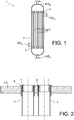
- the figure 1 illustrates schematically, in section, an example of heat exchanger 1 with tubes and shell comprising a shell 2 in which are arranged thin tubes 3 between two upper tube plates 4 and lower 5.
- the heat exchanger is traversed by fluids A and B.
- fluid B liquid or gas
- the references I / O B and S / E B respectively designate the inlet / outlet of fluid B and outlet / inlet of fluid B.
- the other fluid here fluid A, vapor or gas, circulates inside the tubes 3.
- the references I / O A and S / E A respectively designate the inlet / outlet of fluid A and outlet / inlet of fluid A.
- the tubes 3 are associated with upper 4 and lower 5 tube plates separating the fluids.
- the figure 2 illustrates an example of the principle of junction between thin tubes 3 and a tube plate 4, 5. This principle is described in particular in the French patent application FR 2 542 437 A1 of the Applicant.
- the general principle of the fasteners is to clamp the tubes 3 between two female conical parts 6 and male 7.
- the female conical part 6 is embedded in the tube plate 4, 5.
- the traction of the tube 3 strengthens the clamping of the external face of the male conical part 7 against the internal face of the female conical part 6, which causes a self-locking effect.
- the device shown in figure 3 of FR 2 577 008 A1 features retractable heated half-jaws that push the end of the tube inward while melting it. In this way, it is impossible to push the material back over the entire periphery of the tube since the movement is carried out only in two directions of the same direction and not according to a symmetry of revolution.
- a radiating device does not make it possible to control the orientation of the bead. It also has no thermal inertia. Controlling the melting temperature without degrading neighboring parts is critical.
- the aim of the invention is to at least partially remedy the needs mentioned above and the drawbacks relating to the embodiments of the prior art.
- the subject of the invention is a device for fixing a tube to a tube plate of a heat exchanger according to claim 1.
- the invention uses hot gas blowing, in particular hot air.
- the invention it may therefore be possible to avoid any contact between the material of the tube and any tooling effecting the fusion.
- the invention facilitates the melting of the material of the thin tube, its free end voluntarily protruding from the assembly of the two male and female fasteners in the final position.
- the invention can allow orientation of the molten material of the tube so as to fold it in a controlled direction.
- the invention allows the integrity of the fasteners and of the tube to be respected outside the fusion zone.
- the device according to the invention can also include one or more of the following characteristics taken in isolation or according to any possible technical combination.
- the tube is a thin tube. Its thickness is for example between 40 and 200 ⁇ m.
- the presence of the closure element makes it possible to prevent the hot gas stream from penetrating inside the tube, which would have the effect of destroying the tube by melting or by deformation (heat-shrinkable effect) given its very low thickness and its usual manufacturing process.
- the closure element may include a shoulder capable of coming to bear against the male fixing part.
- the material or materials constituting the closure element may have a higher melting point than the melting temperature of the material or materials constituting the tube.
- the material or materials of the closure element are preferably chosen in order to have good resistance to temperature so as not to also melt when the free end of the tube melts to form the bead. They also preferably have a high thermal inertia so as not to not transmit heat to areas not affected by the bead forming operation.
- the closure element may comprise a fluoropolymer, in particular polytetrafluoroethylene (PTFE).
- PTFE polytetrafluoroethylene
- closure element may include a recess, in particular in the form of a V, on its outer surface outside the tube.
- the closure element may also advantageously include an end for insertion into the tube of frustoconical shape so as to facilitate the installation of this closure element.
- closure element is, according to the invention, partially hollow, thus comprising a hot gas injection orifice, and comprising at least one peripheral orifice, or peripheral lumen, allowing the passage of hot gas to come. directly in contact with the free end of the tube.
- the passage of hot gas through the injection orifice, then through one or more peripheral orifices makes it possible to melt the material of the free end of the tube and to form the bead which is pushed outwards under the effect of the speed of the hot gas.
- the orientation of the second portion makes it possible to be able to push back the material from the free end of the tube in the axial direction, in other words along the longitudinal axis of the tube.
- This orientation advantageously makes it possible to push back the material against the assembly of the male and female fasteners, which has the advantage of blocking the expulsion of the male fastener to the outside and also of eliminating the risk of thinning of the tube when it is pushed out.
- the orientation of the fourth portion advantageously makes it possible to direct the hot gas outwards in a vertical direction, namely along the longitudinal axis of the tube, so as not to disturb the adjacent tubes.
- the shutter element may comprise, in its hollow portion, a movable shutter, in particular a sliding shutter, between a so-called “open” position allowing the passage of hot gas through the shutter element towards said at least one. a peripheral orifice, and a so-called “closed” position in which the hot gas escapes to the outside of the closure element through a discharge opening formed in the wall of the hollow portion of the shutter element.
- a further subject of the invention is a method of forming a bead at a free end of a tube according to claim 9.
- the hot gas blowing temperature in particular hot air, is advantageously a direct function of the material to be melted, in particular of the polymer material of the tube to be melted.
- the blowing temperature is of the order of 360 ° C to melt the free end for a source of hot gas located about twenty centimeters from the free end in order to obtain the bead by fusion.
- the hot gas blowing can be carried out by means of a suitable hot gas blowing device, in particular a device the temperature of which is regulated and adjustable, such as for example a hot air gun commonly used in plastics processing.
- a suitable hot gas blowing device in particular a device the temperature of which is regulated and adjustable, such as for example a hot air gun commonly used in plastics processing.
- the method is carried out using a fixing device according to claim 1.
- the method may include the step of placing the closure element in the second bore of the male fastener before the blowing of the hot gas so as to prevent entry of hot gas into the tube, then the step of removing the closure member after formation of the bead.
- a fixing device 10 allows the fixing of thin tubes 3, that is to say of a thickness advantageously between 40 and 200 ⁇ m, on a tube plate 4 , 5 as described above of a heat exchanger 1, for example an evapo-condenser or a gas / gas heat exchanger as described previously.
- FIG. 1 there is partially illustrated, in section, a first embodiment of a fixing device 10, the figure 4 illustrating more precisely two examples of such fastening devices 10 with the tubes 3 mounted in openings 12 of a tube plate 4, 5 of a heat exchanger 1.
- such a device 10 for fixing a tube 3 comprises first of all a female fixing part 6 (or alternatively female ring), which comprises a first bore 13 of frustoconical shape.
- This female fastener 6 is inserted into an opening 12 of the tube plate 4, 5, as visible on the figure. figure 4 .
- the fixing device 10 also comprises a male fixing part 7 (or even male sleeve) of frustoconical exterior shape.
- This male fastener 7 is itself inserted into the first bore 13 of the female fastener 6 so that the tube 3 is held, or even “pinched”, between the female fastener 6 and the fastener.
- male 7 is itself inserted into the first bore 13 of the female fastener 6 so that the tube 3 is held, or even “pinched”, between the female fastener 6 and the fastener. male 7.
- the tube 3 is held between the two fasteners 6 and 7 so that a free end 3a of the tube 3 protrudes from the holding zone of the tube 3.
- the male fastening piece 7 comprises a second bore 14, and the fastening device 10 further comprises a closure element 11, in the form a plug 11, making it possible to close the second bore 14 in order to prevent hot gas, in particular hot AC air, from entering the tube 3.
- this hot air AC allows the formation of a bead at the free end 3a of the tube 3.
- this method comprises the step of blowing hot air AC on this free end 3a of the tube 3 so as to cause the latter to melt to form the bead.
- the hot air blowing temperature AC is directly dependent on the material to be melted, in particular the polymer material of the tube to be melted.
- the tube 3, and therefore its free end 3a can advantageously be made of plastic, and therefore of different types of polymer materials.
- the blowing temperature is of the order of 360 ° C to melt the free end 3a for a source of hot air located approximately twenty centimeters from the free end 3a in order to obtain the bead by fusion.
- the blowing can be carried out by means of a suitable blowing device, in particular a device the temperature of which is regulated and adjustable, such as for example a hot air gun commonly used in plastics processing.
- a suitable blowing device in particular a device the temperature of which is regulated and adjustable, such as for example a hot air gun commonly used in plastics processing.
- the free end 3a of the tube 3 is then melted by moving the blowing device around the tube.
- the presence of the plug 11 makes it possible to prevent the current of hot air from penetrating inside the tube 3, which would have the effect of destroying the tube 3 by melting or by deformation (heat-shrinkable effect). - Due to its very low thickness and its usual manufacturing process. Also, during the formation of the bead, the method according to the invention firstly comprises the step of placing the plug 11 in the second bore 14 of the male fastening part 7 before the hot air blowing AC, then the step of removing the plug 11 after formation of the bead.
- the material or materials constituting the stopper 11 have a higher melting temperature than the melting temperature of the material or materials constituting the tube 3, which makes it possible to melt the tube 3, and more precisely its free end 3a, to form the bead without however melting the stopper 11.
- the stopper 11 will thus be formed by a fluoropolymer, in particular polytetrafluoroethylene (PTFE).
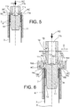
- the figures 5 and 6 now partially illustrate, in section, two exemplary embodiments of a fixing device 10 according to the invention.
- These exemplary embodiments use specific dedicated tooling at the level of the stopper 11 so as to guarantee the reproducibility of the result and to better control the process for forming the bead.
- the time of exposure to the hot air flow AC of the part to be melted is a critical parameter.
- the stopper 11 has a V-shaped recess 11d on its outer surface outside the tube 3.
- the stopper 11 is partially hollow. More precisely, it comprises, above this V-shaped recess 11d, an injection orifice 11b of hot air AC.
- it also comprises peripheral orifices 11c, or even peripheral openings, which allow the passage of hot air AC to come directly into contact with the free end 3a of the tube 3.
- the stopper 11 also has a lower end for insertion into the tube 3 which has a frustoconical shape so as to facilitate the fitting of the stopper 11.
- the passage of hot air AC through the injection orifice 11b, then through the peripheral orifices 11c makes it possible to melt the material of the free end 3a of the tube 3 and to form the bead which is pushed outwards under the effect of the hot air speed AC.
- the plug 11 is partially hollow at the level of the injection orifice 11b of so as to receive the hot air flow AC.
- the peripheral orifices 11c allow the hot air AC to escape which comes directly into contact with the free end 3a beyond the tube 3. The material is thus melted and the bead is pushed outwards under the effect of the speed of the tube. gas.
- each peripheral orifice 11c is designed differently in order to better direct the flow of hot air AC in contact with the tube 3. More particularly, each peripheral orifice 11c comprises a first portion 16a extending substantially perpendicular to the longitudinal axis X of the tube. 3, then a second portion 16b extending substantially parallel to the longitudinal axis X of the tube 3 in which extends the free end 3a of the tube 3 to be heated to form the bead, then a third portion 16c extending substantially perpendicular to the longitudinal axis X of the tube 3, and finally a fourth portion 16d extending substantially parallel to the longitudinal axis X of the tube 3.
- the hot air flow AC is distributed perpendicularly, at the level of the first portion 16a, at the free end 3a projecting from the thin tube 3 so as to push the material in the axial direction.
- This orientation makes it possible to push the material against the assembly of the fasteners 6 and 7, which has the advantage of blocking the expulsion of the male fastener 7 towards the outside and also of eliminating the risk of thinning. of the thin tube 3 when pushed out.
- the hot air AC is then directed to the outside in a vertical direction so as not to disturb the adjacent tubes 3.
- the cap 11 comprises, in this example of the figure 6 but this could also be the case for the example of the figure 5 , in its hollow portion, a movable shutter sliding 18 between a so-called “open” position allowing the passage of hot air AC in the plug 11 towards the peripheral orifices 11c, and a position called “closed” in which the hot air AC escapes to the outside of the plug 11 through a discharge opening 19 formed in the wall of the hollow portion of the plug 11.
- the total stroke D, visible on the figure 6 , shutter sliding 18 may be substantially equal to the internal diameter of the cap 11 in its part comprising the shutter 18.
- the sliding shutter 18 directs the hot air AC towards the thin tube 3 or towards the outside. It can be combined with a calibration of the exact time for obtaining the bead, thus ensuring the reproducibility of the operation.
- the figures 7 and 8 partially illustrate, in top view, an exemplary sliding shutter 18 for a device 10 according to the invention, respectively in position allowing fusion and in standby position.
- the shutter 18 comprises a first part 19 comprising a first opening 20 for the passage of hot air AC.
- This first part 19 is integral with a cover 24.
- the shutter 18 comprises a second part 21 comprising a second opening 22 for the passage of hot air AC, opening onto a third opening 23 formed in the wall of the part two 21.
- the first 19 and second 21 parts are mounted to slide with respect to one another so as to be able to occupy a first position allowing the passage of hot air AC to the tube 3 to form the bead, as visible on the figure. figure 7 , wherein the cover 24 bears against the wall of the second part 21 comprising the third opening 23 to prevent the passage of hot air AC through the third opening 23, the first 20 and second 24 openings being at least partially superimposed to allow the passage of hot AC air.
- first 19 and second 21 parts are slidably mounted relative to each other so as to be able to also occupy a second position, as visible on the figure. figure 8 , preventing the passage of hot air AC towards the tube 3 by directing it towards the outside of the tube 3, the first 20 and second 22 openings not being superimposed between them and the cover 24 not closing the third opening 23 so that the hot air AC is thus able to circulate through the second opening 22 and then through the third opening 23 to escape to the outside.
- the section of the second part 21 is of square shape on the figures 7 and 8 .
- it can be from another shape, for example circular, the shape of the shutter 18 being able to be adapted according to the needs.
- the cover 24 closes the third opening 23 and the hot air AC circulates through the second opening 22 to be directed towards the tube 3 to be melted.
- the first part 19 is pulled so as to release the third opening 23 through which the hot air AC escapes to the outside, its passage towards the thin tube 3 being blocked.
Landscapes
- Engineering & Computer Science (AREA)
- Mechanical Engineering (AREA)
- Physics & Mathematics (AREA)
- Thermal Sciences (AREA)
- General Engineering & Computer Science (AREA)
- Chemical & Material Sciences (AREA)
- Combustion & Propulsion (AREA)
- Lining Or Joining Of Plastics Or The Like (AREA)
- Heat-Exchange Devices With Radiators And Conduit Assemblies (AREA)
Claims (10)
- Vorrichtung (10) zum Befestigen eines Rohres (3) an einen Rohrboden (4, 5) eines Wärmetauschers (1), enthaltend:- ein Befestigungsaufnahmeteil (6), das eine erste kegelstumpfförmige Bohrung (13) aufweist, wobei das Befestigungsaufnahmeteil (6) dazu bestimmt ist, in eine Öffnung (12) des Rohrbodens (4, 5) eingeführt zu werden,- ein außen kegelstumpfförmiges Befestigungseinsteckteil (7), das dazu geeignet ist, in die erste Bohrung (13) des Befestigungsaufnahmeteils (6) eingeführt zu werden, so dass das Rohr (3) zwischen dem Befestigungsaufnahmeteil (6) und dem Befestigungseinsteckteil (7) gehalten wird,wobei das Befestigungseinsteckteil (7) eine zweite Bohrung (14) aufweist und die Vorrichtung (10) ferner ein Verschlusselement (11) zum Verschließen der zweiten Bohrung (14) aufweist, um zu verhindern, dass heißes Gas (AC) in das Rohr (3) eintritt, wobei das heiße Gas (AC) die Bildung eines Wulstes an einem freien Ende (3a) des Rohres (3) ermöglicht,
dadurch gekennzeichnet, dass
das Verschlusselement (11) teilweise hohl ist und somit eine Einspritzöffnung (11b) zum Einspritzen von heißem Gas (AC) und zumindest eine umlaufende Öffnung (11c) aufweist, die den Durchtritt von heißem Gas (AC) ermöglicht, um direkt mit dem freien Ende (3a) des Rohrs (3) in Kontakt zu gelangen. - Vorrichtung nach Anspruch 1,
dadurch gekennzeichnet, dass
das Verschlusselement (11) eine Schulter (11a) aufweist, die dazu geeignet ist, mit dem Befestigungseinsteckteil (7) in Anlage zu gelangen. - Vorrichtung nach Anspruch 1 oder 2,
dadurch gekennzeichnet, dass
das bzw. die Materialien, aus dem bzw. denen das Verschlusselement (11) besteht, eine höhere Schmelztemperatur als die Schmelztemperatur des bzw. der Materialien aufweisen, aus dem bzw. denen das Rohr (3) besteht. - Vorrichtung nach einem der vorangehenden Ansprüche,
dadurch gekennzeichnet, dass
das Verschlusselement (11) ein Fluorpolymer, insbesondere Polytetrafluorethylen (PTFE), enthält. - Vorrichtung nach einem der vorangehenden Ansprüche,
dadurch gekennzeichnet, dass
das Verschlusselement (11) ein Einführende zum Einführen in das kegelstumpfförmige Rohr (3) aufweist. - Vorrichtung nach einem der vorangehenden Ansprüche,
dadurch gekennzeichnet, dass
die zumindest eine umlaufende Öffnung (11c) aufweist:- einen ersten Abschnitt (16a), der sich im Wesentlichen senkrecht zur Längsachse (X) des Rohrs (3) erstreckt,- einen zweiten Abschnitt (16b), der sich im Wesentlichen parallel zur Längsachse (X) des Rohrs (3) erstreckt und in welchem sich das freie Ende (3a) des Rohrs (3) erstreckt, das zum Bilden des Wulstes erhitzt werden soll,- einen dritten Abschnitt (16c), der sich im Wesentlichen senkrecht zur Längsachse (X) des Rohres (3) erstreckt, und- einen vierten Abschnitt (16d), der sich im Wesentlichen parallel zur Längsachse (X) des Rohres (3) erstreckt. - Vorrichtung nach einem der vorangehenden Ansprüche,
dadurch gekennzeichnet, dass
das Verschlusselement (11) in seinem hohlen Abschnitt einen beweglichen Verschluss (18), insbesondere einen verschiebbaren Verschluss, enthält, der zwischen einer "offenen" Stellung, in welcher der Durchtritt von heißem Gas (AC) in dem Verschlusselement (11) zu der zumindest einen umlaufenden Öffnung (11c) möglich ist, und einer "geschlossenen" Stellung beweglich ist, in welcher das heiße Gas (AC) vom Verschlusselement (11) durch eine Abführöffnung (19) nach außen entweicht, die in der Wandung des hohlen Abschnitts des Verschlusselements (11) ausgebildet ist. - Vorrichtung nach Anspruch 7,
dadurch gekennzeichnet, dass
der bewegliche Verschluss (18) enthält:- ein erstes Teilstück (19), das eine erste Öffnung (20) zum Durchtritt von heißem Gas (AC) aufweist, wobei das erste Teilstück (19) fest mit einer Abdeckung (24) verbunden ist,- ein zweites Teilstück (21), das eine zweite Öffnung (22) zum Durchtritt von heißem Gas (AC) aufweist, die in eine dritte Öffnung (23) mündet, die in der Wandung des zweiten Teilstücks (21) ausgebildet ist,wobei das erste (19) und das zweite Teilstück (21) verschiebbar zueinander gelagert sind, so dass sie eine erste Stellung einnehmen können, die den Durchtritt von heißem Gas (AC) zum Rohr (3) gestattet, um den Wulst auszubilden, in welcher Stellung die Abdeckung (24) in Anlage an der Wandung des zweiten Teilstücks (21) ist, welche die dritte Öffnung (23) aufweist, um den Durchtritt von heißem Gas (AC) durch die dritte Öffnung (23) zu verhindern, und in welcher die erste (20) und die zweite Öffnung (22) zumindest teilweise übereinanderliegen, um den Durchtritt von heißem Gas (AC) zu gestatten, sowie eine zweite Stellung einnehmen können, welche den Durchtritt von heißem Gas (AC) zum Rohr (3) verhindert, indem es nach außerhalb des Rohrs (3) geleitet wird, in welcher Stellung die erste (20) und die zweite Öffnung (24) nicht übereinanderliegen und in welcher die Abdeckung (24) nicht die dritte Öffnung (23) verschließt, wobei das heiße Gas (AC) somit in der Lage ist, durch die zweite Öffnung (22) und dann durch die dritte Öffnung (23) hindurch zu strömen, um nach außen zu entweichen. - Verfahren zum Ausbilden eines Wulstes im Bereich von einem freien Ende (3a) eines Rohres (3), wobei das Rohr (3) an einen Rohrboden (4, 5) eines Wärmetauschers (1) über eine Befestigungsvorrichtung (10) nach einem der vorangehenden Ansprüche befestigt ist, wobei sich das freie Ende (3a) des Rohres (3) außerhalb des Abschnitts des Rohres (3) befindet, der zwischen dem Befestigungsaufnahmeteil (6) und dem Befestigungseinsteckteil (7) gehalten ist,
wobei das Verfahren den Schritt des Einblasens von einem heißen Gas (AC), insbesondere von heißer Luft, auf das freie Ende (3a) des Rohrs (3) umfasst, so dass das Schmelzen des freien Endes (3a) zum Ausbilden eines Wulstes hervorgerufen wird. - Verfahren nach Anspruch 9,
dadurch gekennzeichnet, dass
es den Schritt des Anordnens des Verschlusselements (11) in der zweiten Bohrung (14) des Befestigungseinsteckteils (7) vor dem Einblasen von heißem Gas (AC) umfasst, so dass ein Eintreten von heißem Gas (AC) in das Rohr (3) verhindert wird, sowie den Schritt des Entfernens des Verschlusselements (11) nach dem Ausbilden des Wulstes.
Applications Claiming Priority (1)
| Application Number | Priority Date | Filing Date | Title |
|---|---|---|---|
| FR1761511A FR3074571B1 (fr) | 2017-12-01 | 2017-12-01 | Dispositif de fixation d'un tube sur une plaque tubulaire d'un echangeur de chaleur comportant un element d'obturation |
Publications (2)
| Publication Number | Publication Date |
|---|---|
| EP3492246A1 EP3492246A1 (de) | 2019-06-05 |
| EP3492246B1 true EP3492246B1 (de) | 2020-08-19 |
Family
ID=61802058
Family Applications (1)
| Application Number | Title | Priority Date | Filing Date |
|---|---|---|---|
| EP18209381.5A Active EP3492246B1 (de) | 2017-12-01 | 2018-11-30 | Verschlusselement umfassende befestigungsvorrichtung einer leitung auf einem rohrboden eines wärmetauschers |
Country Status (3)
| Country | Link |
|---|---|
| EP (1) | EP3492246B1 (de) |
| ES (1) | ES2831009T3 (de) |
| FR (1) | FR3074571B1 (de) |
Family Cites Families (2)
| Publication number | Priority date | Publication date | Assignee | Title |
|---|---|---|---|---|
| FR2577008B1 (fr) * | 1985-02-04 | 1987-09-25 | Commissariat Energie Atomique | Dispositif de fixation d'un tube par formation d'un bourrelet, procede de realisation dudit bourrelet, et dispositifs de mise en oeuvre du procede |
| AT506724B1 (de) * | 2007-11-29 | 2013-06-15 | Rosenkranz Helmut Ing | Verfahren zum schweissen von teilen aus thermoplastischen materialien |
-
2017
- 2017-12-01 FR FR1761511A patent/FR3074571B1/fr not_active Expired - Fee Related
-
2018
- 2018-11-30 EP EP18209381.5A patent/EP3492246B1/de active Active
- 2018-11-30 ES ES18209381T patent/ES2831009T3/es active Active
Non-Patent Citations (1)
| Title |
|---|
| None * |
Also Published As
| Publication number | Publication date |
|---|---|
| ES2831009T3 (es) | 2021-06-07 |
| FR3074571A1 (fr) | 2019-06-07 |
| EP3492246A1 (de) | 2019-06-05 |
| FR3074571B1 (fr) | 2020-01-03 |
Similar Documents
| Publication | Publication Date | Title |
|---|---|---|
| CA2843149C (fr) | Connecteurs a flux direct anti-goutte et a verrouillage securise | |
| EP1273843A1 (de) | Wiederverwendbare Kupplung zum Verbinden von verstärkten Schlauchenden | |
| EP2230065A1 (de) | Formwerkzeug zum Warmformen mit Wärmedämmung, und entsprechendes Verfahren | |
| FR3081964A1 (fr) | Scellage de structures creuses | |
| EP1105238B1 (de) | Abstreifvorrichtung für ein rohr | |
| EP3492246B1 (de) | Verschlusselement umfassende befestigungsvorrichtung einer leitung auf einem rohrboden eines wärmetauschers | |
| FR2707233A1 (fr) | Obturateur à souder par collage pour une ouverture pratiquée dans une tôle. | |
| EP4034819B1 (de) | Kondensationswärmetauscher | |
| EP1476332B1 (de) | Gasgenerator | |
| CH359679A (fr) | Cuvette pour calandre | |
| EP0012672B1 (de) | Demontierbare Befestigungsvorrichtung eines elektrischen Widerstandsheizkörpers im Druckausgleichbehälter eines Kernreaktors | |
| EP0687884A1 (de) | Hülle gegen Durchbiegung | |
| FR3063923A1 (fr) | Procede d'assemblage d'un insert sur un support, et insert a assembler sur un support | |
| FR2525350A1 (fr) | Cable de fibres optiques | |
| FR3074877B1 (fr) | Canalisation tubulaire longitudinale comportant un organe intercalaire et procedes de montage et de cintrage d'une telle canalisation | |
| FR2952269A1 (fr) | Ruban thermique, procede de mise en place d'un revetement sur une jonction entre deux tuyaux et procede de fabrication d'un pipeline. | |
| EP3610185B1 (de) | Verfahren zum befestigen eines verankerungselements an einem element der panzerung eines flexiblen rohrs, zugehöriges rohr und zugehöriges montageverfahren | |
| EP0220992B1 (de) | Vorrichtung zum Trennen von konischen Verbindungen in der Glasindustrie | |
| EP3156555B1 (de) | Aufhängung für dämmmaterial mit umkehrbarer verriegelung | |
| EP0193425B1 (de) | Verfahren zur Befestigung eines dünnwandigen Rohres zwischen einem konischen Ring und einer konischen Innenhülse und Vorrichtung zur Durchführung des Verfahrens | |
| EP0572296B1 (de) | System zum chemischen Einmauern von einem Befestigungselement in einem hohlen Material | |
| FR2995294A1 (fr) | Dispositif de jonction d'elements tubulaires notamment pour la fabrication de rampes | |
| BE615702A (fr) | Procede et dispositif pour la fermeture etanche de tubes a fusion | |
| FR2864633A1 (fr) | Tube plastique avec lentille optique integree notamment pour camera endoscopique et procede de fabrication et de mise en place | |
| FR3154534A1 (fr) | Dispositif de maintien de deux éléments rapportés l'un sur l'autre, notamment dans un réacteur nucléaire compact |
Legal Events
| Date | Code | Title | Description |
|---|---|---|---|
| PUAI | Public reference made under article 153(3) epc to a published international application that has entered the european phase |
Free format text: ORIGINAL CODE: 0009012 |
|
| STAA | Information on the status of an ep patent application or granted ep patent |
Free format text: STATUS: REQUEST FOR EXAMINATION WAS MADE |
|
| 17P | Request for examination filed |
Effective date: 20181130 |
|
| AK | Designated contracting states |
Kind code of ref document: A1 Designated state(s): AL AT BE BG CH CY CZ DE DK EE ES FI FR GB GR HR HU IE IS IT LI LT LU LV MC MK MT NL NO PL PT RO RS SE SI SK SM TR |
|
| AX | Request for extension of the european patent |
Extension state: BA ME |
|
| GRAP | Despatch of communication of intention to grant a patent |
Free format text: ORIGINAL CODE: EPIDOSNIGR1 |
|
| STAA | Information on the status of an ep patent application or granted ep patent |
Free format text: STATUS: GRANT OF PATENT IS INTENDED |
|
| RIC1 | Information provided on ipc code assigned before grant |
Ipc: F28D 21/00 20060101ALN20200218BHEP Ipc: F28F 9/16 20060101ALI20200218BHEP Ipc: B29C 65/10 20060101AFI20200218BHEP Ipc: B29C 57/02 20060101ALN20200218BHEP Ipc: B29C 65/00 20060101ALI20200218BHEP Ipc: F28F 9/14 20060101ALN20200218BHEP Ipc: F28F 21/06 20060101ALI20200218BHEP Ipc: B29C 65/56 20060101ALI20200218BHEP Ipc: F28F 9/04 20060101ALN20200218BHEP Ipc: F28D 7/16 20060101ALN20200218BHEP |
|
| INTG | Intention to grant announced |
Effective date: 20200313 |
|
| GRAS | Grant fee paid |
Free format text: ORIGINAL CODE: EPIDOSNIGR3 |
|
| GRAA | (expected) grant |
Free format text: ORIGINAL CODE: 0009210 |
|
| STAA | Information on the status of an ep patent application or granted ep patent |
Free format text: STATUS: THE PATENT HAS BEEN GRANTED |
|
| AK | Designated contracting states |
Kind code of ref document: B1 Designated state(s): AL AT BE BG CH CY CZ DE DK EE ES FI FR GB GR HR HU IE IS IT LI LT LU LV MC MK MT NL NO PL PT RO RS SE SI SK SM TR |
|
| REG | Reference to a national code |
Ref country code: CH Ref legal event code: EP |
|
| REG | Reference to a national code |
Ref country code: DE Ref legal event code: R096 Ref document number: 602018007092 Country of ref document: DE |
|
| REG | Reference to a national code |
Ref country code: AT Ref legal event code: REF Ref document number: 1303451 Country of ref document: AT Kind code of ref document: T Effective date: 20200915 |
|
| REG | Reference to a national code |
Ref country code: IE Ref legal event code: FG4D Free format text: LANGUAGE OF EP DOCUMENT: FRENCH |
|
| REG | Reference to a national code |
Ref country code: LT Ref legal event code: MG4D |
|
| REG | Reference to a national code |
Ref country code: NL Ref legal event code: MP Effective date: 20200819 |
|
| PG25 | Lapsed in a contracting state [announced via postgrant information from national office to epo] |
Ref country code: SE Free format text: LAPSE BECAUSE OF FAILURE TO SUBMIT A TRANSLATION OF THE DESCRIPTION OR TO PAY THE FEE WITHIN THE PRESCRIBED TIME-LIMIT Effective date: 20200819 Ref country code: BG Free format text: LAPSE BECAUSE OF FAILURE TO SUBMIT A TRANSLATION OF THE DESCRIPTION OR TO PAY THE FEE WITHIN THE PRESCRIBED TIME-LIMIT Effective date: 20201119 Ref country code: LT Free format text: LAPSE BECAUSE OF FAILURE TO SUBMIT A TRANSLATION OF THE DESCRIPTION OR TO PAY THE FEE WITHIN THE PRESCRIBED TIME-LIMIT Effective date: 20200819 Ref country code: HR Free format text: LAPSE BECAUSE OF FAILURE TO SUBMIT A TRANSLATION OF THE DESCRIPTION OR TO PAY THE FEE WITHIN THE PRESCRIBED TIME-LIMIT Effective date: 20200819 Ref country code: FI Free format text: LAPSE BECAUSE OF FAILURE TO SUBMIT A TRANSLATION OF THE DESCRIPTION OR TO PAY THE FEE WITHIN THE PRESCRIBED TIME-LIMIT Effective date: 20200819 Ref country code: NO Free format text: LAPSE BECAUSE OF FAILURE TO SUBMIT A TRANSLATION OF THE DESCRIPTION OR TO PAY THE FEE WITHIN THE PRESCRIBED TIME-LIMIT Effective date: 20201119 Ref country code: PT Free format text: LAPSE BECAUSE OF FAILURE TO SUBMIT A TRANSLATION OF THE DESCRIPTION OR TO PAY THE FEE WITHIN THE PRESCRIBED TIME-LIMIT Effective date: 20201221 |
|
| REG | Reference to a national code |
Ref country code: AT Ref legal event code: MK05 Ref document number: 1303451 Country of ref document: AT Kind code of ref document: T Effective date: 20200819 |
|
| PG25 | Lapsed in a contracting state [announced via postgrant information from national office to epo] |
Ref country code: LV Free format text: LAPSE BECAUSE OF FAILURE TO SUBMIT A TRANSLATION OF THE DESCRIPTION OR TO PAY THE FEE WITHIN THE PRESCRIBED TIME-LIMIT Effective date: 20200819 Ref country code: NL Free format text: LAPSE BECAUSE OF FAILURE TO SUBMIT A TRANSLATION OF THE DESCRIPTION OR TO PAY THE FEE WITHIN THE PRESCRIBED TIME-LIMIT Effective date: 20200819 Ref country code: RS Free format text: LAPSE BECAUSE OF FAILURE TO SUBMIT A TRANSLATION OF THE DESCRIPTION OR TO PAY THE FEE WITHIN THE PRESCRIBED TIME-LIMIT Effective date: 20200819 Ref country code: PL Free format text: LAPSE BECAUSE OF FAILURE TO SUBMIT A TRANSLATION OF THE DESCRIPTION OR TO PAY THE FEE WITHIN THE PRESCRIBED TIME-LIMIT Effective date: 20200819 Ref country code: IS Free format text: LAPSE BECAUSE OF FAILURE TO SUBMIT A TRANSLATION OF THE DESCRIPTION OR TO PAY THE FEE WITHIN THE PRESCRIBED TIME-LIMIT Effective date: 20201219 |
|
| PG25 | Lapsed in a contracting state [announced via postgrant information from national office to epo] |
Ref country code: SM Free format text: LAPSE BECAUSE OF FAILURE TO SUBMIT A TRANSLATION OF THE DESCRIPTION OR TO PAY THE FEE WITHIN THE PRESCRIBED TIME-LIMIT Effective date: 20200819 Ref country code: RO Free format text: LAPSE BECAUSE OF FAILURE TO SUBMIT A TRANSLATION OF THE DESCRIPTION OR TO PAY THE FEE WITHIN THE PRESCRIBED TIME-LIMIT Effective date: 20200819 Ref country code: CZ Free format text: LAPSE BECAUSE OF FAILURE TO SUBMIT A TRANSLATION OF THE DESCRIPTION OR TO PAY THE FEE WITHIN THE PRESCRIBED TIME-LIMIT Effective date: 20200819 Ref country code: DK Free format text: LAPSE BECAUSE OF FAILURE TO SUBMIT A TRANSLATION OF THE DESCRIPTION OR TO PAY THE FEE WITHIN THE PRESCRIBED TIME-LIMIT Effective date: 20200819 Ref country code: EE Free format text: LAPSE BECAUSE OF FAILURE TO SUBMIT A TRANSLATION OF THE DESCRIPTION OR TO PAY THE FEE WITHIN THE PRESCRIBED TIME-LIMIT Effective date: 20200819 |
|
| REG | Reference to a national code |
Ref country code: DE Ref legal event code: R097 Ref document number: 602018007092 Country of ref document: DE |
|
| PG25 | Lapsed in a contracting state [announced via postgrant information from national office to epo] |
Ref country code: AT Free format text: LAPSE BECAUSE OF FAILURE TO SUBMIT A TRANSLATION OF THE DESCRIPTION OR TO PAY THE FEE WITHIN THE PRESCRIBED TIME-LIMIT Effective date: 20200819 Ref country code: AL Free format text: LAPSE BECAUSE OF FAILURE TO SUBMIT A TRANSLATION OF THE DESCRIPTION OR TO PAY THE FEE WITHIN THE PRESCRIBED TIME-LIMIT Effective date: 20200819 |
|
| REG | Reference to a national code |
Ref country code: ES Ref legal event code: FG2A Ref document number: 2831009 Country of ref document: ES Kind code of ref document: T3 Effective date: 20210607 |
|
| PLBE | No opposition filed within time limit |
Free format text: ORIGINAL CODE: 0009261 |
|
| STAA | Information on the status of an ep patent application or granted ep patent |
Free format text: STATUS: NO OPPOSITION FILED WITHIN TIME LIMIT |
|
| PG25 | Lapsed in a contracting state [announced via postgrant information from national office to epo] |
Ref country code: SK Free format text: LAPSE BECAUSE OF FAILURE TO SUBMIT A TRANSLATION OF THE DESCRIPTION OR TO PAY THE FEE WITHIN THE PRESCRIBED TIME-LIMIT Effective date: 20200819 Ref country code: MC Free format text: LAPSE BECAUSE OF FAILURE TO SUBMIT A TRANSLATION OF THE DESCRIPTION OR TO PAY THE FEE WITHIN THE PRESCRIBED TIME-LIMIT Effective date: 20200819 |
|
| 26N | No opposition filed |
Effective date: 20210520 |
|
| PG25 | Lapsed in a contracting state [announced via postgrant information from national office to epo] |
Ref country code: LU Free format text: LAPSE BECAUSE OF NON-PAYMENT OF DUE FEES Effective date: 20201130 |
|
| REG | Reference to a national code |
Ref country code: BE Ref legal event code: MM Effective date: 20201130 |
|
| PG25 | Lapsed in a contracting state [announced via postgrant information from national office to epo] |
Ref country code: SI Free format text: LAPSE BECAUSE OF FAILURE TO SUBMIT A TRANSLATION OF THE DESCRIPTION OR TO PAY THE FEE WITHIN THE PRESCRIBED TIME-LIMIT Effective date: 20200819 |
|
| REG | Reference to a national code |
Ref country code: IE Ref legal event code: MM4A |
|
| PG25 | Lapsed in a contracting state [announced via postgrant information from national office to epo] |
Ref country code: IE Free format text: LAPSE BECAUSE OF NON-PAYMENT OF DUE FEES Effective date: 20201130 |
|
| PG25 | Lapsed in a contracting state [announced via postgrant information from national office to epo] |
Ref country code: MT Free format text: LAPSE BECAUSE OF FAILURE TO SUBMIT A TRANSLATION OF THE DESCRIPTION OR TO PAY THE FEE WITHIN THE PRESCRIBED TIME-LIMIT Effective date: 20200819 Ref country code: CY Free format text: LAPSE BECAUSE OF FAILURE TO SUBMIT A TRANSLATION OF THE DESCRIPTION OR TO PAY THE FEE WITHIN THE PRESCRIBED TIME-LIMIT Effective date: 20200819 |
|
| PG25 | Lapsed in a contracting state [announced via postgrant information from national office to epo] |
Ref country code: MK Free format text: LAPSE BECAUSE OF FAILURE TO SUBMIT A TRANSLATION OF THE DESCRIPTION OR TO PAY THE FEE WITHIN THE PRESCRIBED TIME-LIMIT Effective date: 20200819 |
|
| REG | Reference to a national code |
Ref country code: CH Ref legal event code: PL |
|
| PG25 | Lapsed in a contracting state [announced via postgrant information from national office to epo] |
Ref country code: BE Free format text: LAPSE BECAUSE OF NON-PAYMENT OF DUE FEES Effective date: 20201130 |
|
| GBPC | Gb: european patent ceased through non-payment of renewal fee |
Effective date: 20221130 |
|
| PG25 | Lapsed in a contracting state [announced via postgrant information from national office to epo] |
Ref country code: LI Free format text: LAPSE BECAUSE OF NON-PAYMENT OF DUE FEES Effective date: 20220701 Ref country code: CH Free format text: LAPSE BECAUSE OF NON-PAYMENT OF DUE FEES Effective date: 20220701 |
|
| PG25 | Lapsed in a contracting state [announced via postgrant information from national office to epo] |
Ref country code: GB Free format text: LAPSE BECAUSE OF NON-PAYMENT OF DUE FEES Effective date: 20221130 |
|
| PGFP | Annual fee paid to national office [announced via postgrant information from national office to epo] |
Ref country code: TR Payment date: 20241120 Year of fee payment: 7 |
|
| PGFP | Annual fee paid to national office [announced via postgrant information from national office to epo] |
Ref country code: DE Payment date: 20251118 Year of fee payment: 8 |
|
| PGFP | Annual fee paid to national office [announced via postgrant information from national office to epo] |
Ref country code: IT Payment date: 20251128 Year of fee payment: 8 |
|
| PGFP | Annual fee paid to national office [announced via postgrant information from national office to epo] |
Ref country code: FR Payment date: 20251125 Year of fee payment: 8 |
|
| PGFP | Annual fee paid to national office [announced via postgrant information from national office to epo] |
Ref country code: GR Payment date: 20251117 Year of fee payment: 8 |
|
| PGFP | Annual fee paid to national office [announced via postgrant information from national office to epo] |
Ref country code: ES Payment date: 20251216 Year of fee payment: 8 |