EP3491908B1 - Moissonneuse et/ou machine de traitement du sol agricole - Google Patents
Moissonneuse et/ou machine de traitement du sol agricole Download PDFInfo
- Publication number
- EP3491908B1 EP3491908B1 EP18210080.0A EP18210080A EP3491908B1 EP 3491908 B1 EP3491908 B1 EP 3491908B1 EP 18210080 A EP18210080 A EP 18210080A EP 3491908 B1 EP3491908 B1 EP 3491908B1
- Authority
- EP
- European Patent Office
- Prior art keywords
- pressure medium
- actuators
- pressure
- axle carrier
- axle
- Prior art date
- Legal status (The legal status is an assumption and is not a legal conclusion. Google has not performed a legal analysis and makes no representation as to the accuracy of the status listed.)
- Active
Links
Images
Classifications
-
- A—HUMAN NECESSITIES
- A01—AGRICULTURE; FORESTRY; ANIMAL HUSBANDRY; HUNTING; TRAPPING; FISHING
- A01D—HARVESTING; MOWING
- A01D75/00—Accessories for harvesters or mowers
- A01D75/28—Control mechanisms for harvesters or mowers when moving on slopes; Devices preventing lateral pull
-
- A—HUMAN NECESSITIES
- A01—AGRICULTURE; FORESTRY; ANIMAL HUSBANDRY; HUNTING; TRAPPING; FISHING
- A01F—PROCESSING OF HARVESTED PRODUCE; HAY OR STRAW PRESSES; DEVICES FOR STORING AGRICULTURAL OR HORTICULTURAL PRODUCE
- A01F15/00—Baling presses for straw, hay or the like
- A01F15/08—Details
-
- B—PERFORMING OPERATIONS; TRANSPORTING
- B60—VEHICLES IN GENERAL
- B60G—VEHICLE SUSPENSION ARRANGEMENTS
- B60G21/00—Interconnection systems for two or more resiliently-suspended wheels, e.g. for stabilising a vehicle body with respect to acceleration, deceleration or centrifugal forces
- B60G21/002—Interconnection systems for two or more resiliently-suspended wheels, e.g. for stabilising a vehicle body with respect to acceleration, deceleration or centrifugal forces longitudinally
-
- B—PERFORMING OPERATIONS; TRANSPORTING
- B60—VEHICLES IN GENERAL
- B60G—VEHICLE SUSPENSION ARRANGEMENTS
- B60G21/00—Interconnection systems for two or more resiliently-suspended wheels, e.g. for stabilising a vehicle body with respect to acceleration, deceleration or centrifugal forces
- B60G21/02—Interconnection systems for two or more resiliently-suspended wheels, e.g. for stabilising a vehicle body with respect to acceleration, deceleration or centrifugal forces permanently interconnected
- B60G21/023—Interconnection systems for two or more resiliently-suspended wheels, e.g. for stabilising a vehicle body with respect to acceleration, deceleration or centrifugal forces permanently interconnected longitudinally
-
- B—PERFORMING OPERATIONS; TRANSPORTING
- B60—VEHICLES IN GENERAL
- B60G—VEHICLE SUSPENSION ARRANGEMENTS
- B60G21/00—Interconnection systems for two or more resiliently-suspended wheels, e.g. for stabilising a vehicle body with respect to acceleration, deceleration or centrifugal forces
- B60G21/02—Interconnection systems for two or more resiliently-suspended wheels, e.g. for stabilising a vehicle body with respect to acceleration, deceleration or centrifugal forces permanently interconnected
- B60G21/06—Interconnection systems for two or more resiliently-suspended wheels, e.g. for stabilising a vehicle body with respect to acceleration, deceleration or centrifugal forces permanently interconnected fluid
- B60G21/067—Interconnection systems for two or more resiliently-suspended wheels, e.g. for stabilising a vehicle body with respect to acceleration, deceleration or centrifugal forces permanently interconnected fluid between wheels on different axles on the same side of the vehicle, i.e. the left or the right side
-
- B—PERFORMING OPERATIONS; TRANSPORTING
- B60—VEHICLES IN GENERAL
- B60G—VEHICLE SUSPENSION ARRANGEMENTS
- B60G5/00—Resilient suspensions for a set of tandem wheels or axles having interrelated movements
- B60G5/04—Resilient suspensions for a set of tandem wheels or axles having interrelated movements with two or more pivoted arms, the movements of which are resiliently interrelated, e.g. the arms being rigid
- B60G5/06—Resilient suspensions for a set of tandem wheels or axles having interrelated movements with two or more pivoted arms, the movements of which are resiliently interrelated, e.g. the arms being rigid the arms turning on a common pivot, e.g. being rigid
-
- A—HUMAN NECESSITIES
- A01—AGRICULTURE; FORESTRY; ANIMAL HUSBANDRY; HUNTING; TRAPPING; FISHING
- A01F—PROCESSING OF HARVESTED PRODUCE; HAY OR STRAW PRESSES; DEVICES FOR STORING AGRICULTURAL OR HORTICULTURAL PRODUCE
- A01F15/00—Baling presses for straw, hay or the like
- A01F15/07—Rotobalers, i.e. machines for forming cylindrical bales by winding and pressing
- A01F15/071—Wrapping devices
- A01F2015/0735—Combined machines that include a press bale and a wrapping device in a further step, e.g. turning table, not in the same closed pressing chamber
-
- B—PERFORMING OPERATIONS; TRANSPORTING
- B60—VEHICLES IN GENERAL
- B60G—VEHICLE SUSPENSION ARRANGEMENTS
- B60G2200/00—Indexing codes relating to suspension types
- B60G2200/30—Rigid axle suspensions
- B60G2200/318—Rigid axle suspensions two or more axles being mounted on a longitudinal rocking or walking beam
-
- B—PERFORMING OPERATIONS; TRANSPORTING
- B60—VEHICLES IN GENERAL
- B60G—VEHICLE SUSPENSION ARRANGEMENTS
- B60G2204/00—Indexing codes related to suspensions per se or to auxiliary parts
- B60G2204/80—Interactive suspensions; arrangement affecting more than one suspension unit
- B60G2204/81—Interactive suspensions; arrangement affecting more than one suspension unit front and rear unit
-
- B—PERFORMING OPERATIONS; TRANSPORTING
- B60—VEHICLES IN GENERAL
- B60G—VEHICLE SUSPENSION ARRANGEMENTS
- B60G2204/00—Indexing codes related to suspensions per se or to auxiliary parts
- B60G2204/80—Interactive suspensions; arrangement affecting more than one suspension unit
- B60G2204/83—Type of interconnection
- B60G2204/8304—Type of interconnection using a fluid
-
- B—PERFORMING OPERATIONS; TRANSPORTING
- B60—VEHICLES IN GENERAL
- B60G—VEHICLE SUSPENSION ARRANGEMENTS
- B60G2206/00—Indexing codes related to the manufacturing of suspensions: constructional features, the materials used, procedures or tools
- B60G2206/01—Constructional features of suspension elements, e.g. arms, dampers, springs
- B60G2206/011—Modular constructions
- B60G2206/0112—Bogies for heavy vehicles
-
- B—PERFORMING OPERATIONS; TRANSPORTING
- B60—VEHICLES IN GENERAL
- B60G—VEHICLE SUSPENSION ARRANGEMENTS
- B60G2300/00—Indexing codes relating to the type of vehicle
- B60G2300/04—Trailers
-
- B—PERFORMING OPERATIONS; TRANSPORTING
- B60—VEHICLES IN GENERAL
- B60G—VEHICLE SUSPENSION ARRANGEMENTS
- B60G2300/00—Indexing codes relating to the type of vehicle
- B60G2300/04—Trailers
- B60G2300/042—Semi-trailers
-
- B—PERFORMING OPERATIONS; TRANSPORTING
- B60—VEHICLES IN GENERAL
- B60G—VEHICLE SUSPENSION ARRANGEMENTS
- B60G2300/00—Indexing codes relating to the type of vehicle
- B60G2300/08—Agricultural vehicles
-
- B—PERFORMING OPERATIONS; TRANSPORTING
- B60—VEHICLES IN GENERAL
- B60G—VEHICLE SUSPENSION ARRANGEMENTS
- B60G2500/00—Indexing codes relating to the regulated action or device
- B60G2500/30—Height or ground clearance
Definitions
- the present invention relates to an agricultural harvesting and / or soil cultivation machine with a machine frame which is supported on the ground by at least one bogey chassis, which has two wheel axles each attached to an axle carrier, which together with the wheel axles in the manner of a rocker around a pivot axis is pivotably mounted, wherein the axle support for height adjustment of the bogey chassis is divided into at least two axle support parts which are pivotable relative to one another.
- Agricultural harvesting and / or soil cultivation machines such as balers or loading wagons with a pick-up device for picking up crops from the ground are often equipped with bogey chassis, as such bogey chassis on the one hand enable favorable ground adaptation with even load distribution on both axles on the one hand, even on undulating terrain, and on the other allows others to adjust the height of the chassis in a simple manner.
- the height adjustment in the left and right lanes can also be done independently or individually, so that slope compensation can be achieved in a simple manner, i.e. when driving parallel on the slope transversely to the slope, the lower bogey chassis can be higher and / or the uphill chassis deeper be placed so that the machine structure is approximately horizontal or at least less inclined and a certain inclination compensation is achieved.
- this can be useful in order to facilitate the transfer of a completely wrapped bale from the baling chamber to the wrapping device.
- this can be useful in order to achieve an even distribution of forage when distributing the harvested material in the storage space, for example by switching on the scraper floor.
- Such bogey chassis can also be useful on other types of agricultural machinery, for example on seed drills, tillage equipment such as plows, cultivators, harrows or tillage combinations, as well as haymaking machines such as rakes and tedders or other agricultural harvesting or tillage machines, especially if they are used as attachments for cultivation a tractor are trained.
- tillage equipment such as plows, cultivators, harrows or tillage combinations
- haymaking machines such as rakes and tedders or other agricultural harvesting or tillage machines, especially if they are used as attachments for cultivation a tractor are trained.
- the writings EP 3 069 598 A1 , EP 30 69 600 A1 and DE 10 2015 006 221 A1 each show, for example, a baler, the machine frame of which is supported on the ground by a bogey chassis, the rocker-like axle carrier on which the two wheel axles are attached is designed in a split manner and has two mutually pivotable legs in order to be able to adjust the height of the bogey chassis.
- the two legs of the split axle carrier are hinged to a common pivot axis and connected to one another by a setting actuator, so that different angular positions of the axle carrier legs can be set to one another by lengthening or shortening the setting actuator, so that the bogey chassis can be adjusted in height.
- axle support legs When the axle support legs are frozen relative to one another, the entire, then rigid, axle support can rock up and down together with the actuating actuator about the pivot axis in order to implement the bogey driving mode in a manner known per se.
- the writing shows a similar bogey chassis for a bean harvester US 2918292 A .
- such a bogey chassis can also be a hindrance or the mentioned height adjustment can not be sufficient.
- the machine can unintentionally sag as a whole if one of the two wheel axles has driven over the slope edge onto the sloping flank, although the other wheel axle itself would still be placed on the upper section of the slope edge.
- driving over smaller grooves or smaller transverse channels can also lead to restless driving behavior with vertical impacts or vibrations on the machine structure.
- the present invention is based on the object of creating an improved agricultural harvesting and / or soil cultivating machine which avoids the disadvantages of the prior art and further develops the latter in an advantageous manner.
- the chassis supporting the machine frame on the ground is to be further developed in order to maintain the advantages of a bogey chassis, but to eliminate or at least weaken its disadvantages, whereby the chassis should be as simple as possible with few parts despite the height adjustability.
- a Setting device for the variable setting of a fixed, predeterminable angular position of the axle carrier overall with respect to the pivot axis to be provided in order to be able to predetermine a specific pivot position of the axle carrier in the sense of an absolute angular position of the axle carrier relative to the machine frame.
- at least two pressure medium actuators are provided for setting the relative position of the axle support parts to one another and for setting the angular position of the axle support with respect to the pivot axis relative to the machine frame.
- the at least two pressure medium actuators are arranged and designed in such a way that, on the one hand, they enable normal bogey driving with wheel axles rocking up and down in opposite directions, but on the other hand they also enable driving with, so to speak, frozen pivot position of the axle carrier or the fixing of at least one axle carrier part with respect to the pivot axis , and can also adjust the height of the bogey chassis.
- said at least two pressure medium actuators can each be articulated on the one hand to one of the axle support parts and on the other hand to a pivoting axle support, with respect to which the bogey chassis can be luffed.
- Said swivel axle carrier can be, for example, a chassis suspension carrier rigidly connected to the machine frame, but possibly also an adjustable wheel or axle suspension element, with respect to which the axle carrier of the bogey chassis can be pivoted or rocked up and down with both axle carrier parts.
- a pressure medium control device can be provided in a further development of the invention to control the at least two pressure medium actuators mentioned, which provides different operating modes for the pressure medium actuators in which the pressure medium application in is controlled in different ways.
- the said pressure medium control device can have a rocker operating mode in which the pressure medium actuators are short-circuited with one another so that the pressure medium actuators push pressure medium back and forth or pump back and forth according to the displacement principle if corresponding movements of the Pressure medium actuators comes.
- the pressure medium cylinders can be shut off from a pressure medium source and / or from a return to the tank of the pressure medium supply, so that pressure medium is only circulated or displaced back and forth internally between the pressure medium actuators.
- the mentioned pressure medium actuators can be short-circuited in such a way that when one axle carrier part is rocked up or down, the pressure fluid displaced from the associated pressure medium actuator forces an adjusting movement of the other pressure medium actuator, which leads to a counter-rocking down or up of the other axle carrier part connected to the mentioned other pressure medium actuator.
- the pressure medium actuators are thus short-circuited to one another in such a way that they mutually force adjusting movements which lead to pivoting or rocking of the axle carrier parts in the same direction of rotation.
- these can be counter-rotating or synchronous adjusting movements of the pressure actuators.
- two pressure medium cylinders are provided as pressure medium actuators, which are arranged on the same side of the axle support or are articulated on the same side of the pivot axis on the swivel axle support, so that one pressure medium cylinder has to lengthen and the other pressure medium cylinder has to shorten by the axle support overall bogey-like rocking or swiveling one wheel axle upwards and the other wheel axle downwards, the two hydraulic cylinders can be short-circuited crosswise so that pressure fluid that is displaced from one cylinder when it is shortened lengthen the other cylinder enforces.
- the mentioned pressure medium cylinders are arranged on different sides of the axle support or articulated on opposite sides of the pivot axis, for example in a z-like configuration or in a configuration with a cylinder above and a cylinder below the axle support, so that both pressure medium cylinders lengthen by a
- the pressure medium actuators can also be short-circuited to one another in such a way that synchronous adjusting movements result.
- the pressure fluid displaced when one cylinder is shortened also forces a shortening of the other pressure medium cylinder
- the pressure fluid displaced when one pressure medium cylinder is lengthened also forces the other pressure medium cylinder to be lengthened.
- the aforementioned pressure medium control device advantageously also has an actuating mode in which at least one of the aforementioned pressure medium actuators is connected to a pressure source and / or a return in order to move to a predetermined pivot position by applying pressure medium and / or releasing pressure medium, and then in the predetermined position can be determined, for example, in that at least one pressure chamber of the pressure medium actuator is shut off by means of a shut-off valve.
- the pressure medium control device provides an active setting and determination of a predetermined position of the pressure medium actuator so that the axle carrier part connected to it can be determined in an absolute angular position, since the said actuating actuator is as above explains a point of articulation on the pivot axis support or an articulation part connected therewith.
- the pressure medium control device can move and determine both pressure medium actuators by connecting to the pressure source and / or the return in a predetermined absolute angular position relative to the machine frame in the said actuating operating mode, so that the position of both wheel axles of the bogey chassis can be adjusted and determined.
- said pressure medium control device can furthermore have a height adjustment mode in which the two pressure medium actuators are each connected to the mentioned pressure source, possibly also with two separate pressure sources - or a return - possibly also with two separate returns - to adjust the relative angular position of the two Adjust the axle support parts relative to each other and thus adjust the height of the bogey chassis.
- Said pressure medium control device can advantageously comprise a valve device which has various switching positions in which the pressure medium actuators can be short-circuited with one another in the manner described above and optionally connected to a pressure source or a return.
- Said valve device can have a plurality of shut-off valves and / or multi-way valves.
- the mentioned pressure medium actuators and their pressure medium control device are advantageously designed in such a way that the pressure medium actuators move at least approximately synchronized with one another in the mentioned short-circuit or rocker operating mode, so that the axle carrier legs controlled by the pressure medium actuators move at least approximately synchronously with one another, i.e. by approximately the same pivot angle pivot.
- Complete synchronization of the axle support parts is not necessary, but it can be provided so that the axle support legs are actually frozen rigidly to one another in the rocker operating mode and only turn around the pivot axis can rock up and down without performing relative movements to each other.
- the pressure medium actuators can have mutually corresponding displacement volumes so that the adjusting movement of the other pressure medium actuator forced by the displaced pressure fluid of one pressure medium actuator is at least approximately the same in terms of magnitude. If the displacement volumes of the two pressure medium actuators are approximately the same, the pressure medium actuators can be short-circuited directly to one another.
- a compensating cylinder can also be provided in the short-circuit circuit of the two pressure medium actuators, which compensates for different displacement volumes or at least approximates them to a certain extent.
- Such a compensating cylinder can have pressure chambers of different sizes, wherein a pressure chamber with a larger cross section can be connected to the pressure medium actuator with a larger displacement volume and the pressure chamber with a smaller cross-sectional area can be connected to the pressure medium actuator with a smaller displacement volume.
- said pressure medium actuators can be short-circuited with one another in the short-circuit mode in order to carry out movements in opposite directions, or they can be short-circuited parallel to one another in order to carry out movements in the same direction.
- pressure cylinders can be arranged above the axle carrier and have a pivot point on the same side of the pivot axis so that they move in opposite directions, i.e. one pressure cylinder has to lengthen and the other pressure cylinder has to shorten in order to achieve a rocking bogey operation enable.
- said cross-over short circuit can be provided.
- more than two pressure medium actuators can also be provided in a further development of the invention.
- two further pressure medium actuators can be provided, which can be coupled to the two first-mentioned pressure medium actuators in pairs, in particular connected in series, so that the actuating movement of the further pressure medium actuators is transmitted to the respective axle carrier via the first pressure medium actuators.
- a first pressure medium actuator is coupled to a third pressure medium actuator and a second pressure medium actuator is coupled to a fourth pressure medium actuator
- the actuating movement of the third pressure medium actuator can be transmitted to the axle carrier connected to it by the first pressure medium actuator, while an actuating movement of the fourth pressure medium actuator is transmitted to the associated axle carrier is transmitted.
- the two further pressure medium actuators - the third and fourth pressure medium actuators in the example described above - can be provided to adjust the articulation points of the first two pressure medium actuators - that is, the first and second pressure medium actuators - on the pivot axle support. If the third and fourth pressure medium actuators are retracted or extended, the articulation points of the first and second pressure medium actuators move on the said pivoting kachong.
- the four pressure medium actuators mentioned can be coupled to one another in pairs via transmitters, for example in the form of pivot levers, the pivot levers mentioned each being pivotable on the pivot axis support can be stored.
- a very compact design can be achieved in which the third and fourth pressure medium actuators can be arranged independently of the desired adjustment direction for the articulation points of the first and second pressure medium actuators.
- a step-up or step-down effect can also be achieved via the pivot levers mentioned, which enables the desired adjustment movement with a limited adjustment path of the pressure medium actuators and / or a limited size of the pressure medium actuators.
- the pressure medium control device in its rocker operating mode can in itself short-circuit the first and second pressure medium actuators to one another as described above, whereby the third and fourth pressure medium actuators can be blocked or determined so that the bogey or rocker operation can only be achieved by moving the first and second pressure cylinder.
- the pressure medium control device in the rocker operating mode can, however, advantageously also provide a short circuit between the pressure medium cylinders, which also includes the additional third and fourth pressure medium actuators.
- the two first-mentioned pressure medium actuators, which are articulated to the axle support parts, can each be short-circuited with the additional pressure medium actuator, with which they are not connected in series and are not coupled through the said transducer.
- the first pressure medium cylinder - possibly via the pivot lever described - is coupled to the third pressure medium actuator and connected in series in the aforementioned manner, said first pressure medium cylinder can be short-circuited with the fourth pressure medium cylinder, which can be short-circuited with the second pressure medium actuator - if necessary via a further pivot lever - is coupled.
- the named second pressure medium cylinder can then be short-circuited with the aforementioned third pressure medium actuator.
- movements of the first and second pressure medium actuators force corresponding movements of the third and fourth pressure medium actuators, so that all four mentioned pressure medium actuators are adjusted when the axle carrier as a whole, i.e. with both axle carrier parts, rocks up and down about the pivot axis in bogey mode.
- the first-mentioned at least two pressure medium actuators do not have to be articulated in the manner described above, on the one hand, on an axle support half and, on the other hand, on the pivoting axle support or another part fixed to the machine frame.
- the two pressure medium actuators can also have separate or different functional tasks and be articulated differently.
- the one pressure medium actuator can be provided for the height adjustment of the bogey chassis, in particular arranged and designed to pivot the two axle support parts relative to one another, while the other of the at least two pressure medium actuators can be provided to set the absolute angular position of the axle support relative to the machine frame and / or determine.
- one of the two pressure medium actuators can have articulation points on different axle support parts, so that an adjustment of the pressure medium actuator causes the two axle support parts to pivot relative to one another.
- the other of the two pressure medium actuators can on the one hand be articulated on one of the two axle support parts and on the other hand have an articulation point fixed to the machine frame or be articulated on the previously mentioned swivel axle support or an element connected to it, with respect to which the axle support has to rotate when bogey rocking.
- the pressure medium actuators can be individually adapted to their respective task and, in particular, can also be designed differently from one another.
- the pressure medium actuator which adjusts the two axle parts to one another can have a different travel and / or a different travel path have a different piston diameter than the pressure medium actuator, which sets the angular position of the axle parts relative to the machine frame.
- the pressure medium control device for the two pressure medium actuators can also be designed differently, in particular comprise different valve arrangements by means of which the respective pressure medium actuator can be controlled.
- the aforementioned pressure medium control device can, in its rocker operating mode, block the pressure medium actuator, which has articulation points on both axle support parts and is responsible for the height adjustment, for example by locking it to make it unchangeable in length and thus freeze the relative position of the two axle support parts to one another, and Switch the other pressure medium actuator, which has an articulation point fixed to the machine frame, into the floating position.
- said pressure medium control device in its setting mode of operation can move said pressure medium actuator with an articulation point fixed to the machine frame by applying pressure or connecting it to the return line into a predetermined operating position and determine it, with the other pressure medium actuator remaining locked with articulation points on both axle parts or also moving into another position and can then be locked. If necessary, it would also be conceivable to switch the said pressure medium actuator, which has articulation points on both axle support parts, into the floating position, in which case the entire weight of the other axle support part would then be intercepted, which is locked by the pressure medium actuator with the articulation point fixed to the machine frame.
- the pressure control device can include a cornering operating mode in which one of the two wheel axles is relieved and / or raised while the other wheel axle is loaded by the weight of the machine if necessary to be carried together with the support force of the drawbar.
- the rear of the two bogey wheel axles can be relieved and / or raised, which can be done, for example, in that the pressure control device locks and / or applies sufficient pressure to the pressure medium actuator that supports one of the axle support parts, in particular the front axle support part, on the machine frame applied, while the pressure medium actuator, which can adjust the two axle carrier parts relative to one another, is brought into the floating position or is actively pressurized in order to even slightly raise the wheel axle.
- the pressure medium control device can work as a function of a cornering signal, wherein such a cornering signal can be obtained or provided in different ways.
- a cornering signal can be obtained or provided in different ways.
- this can be a steering angle signal from the tractor that indicates the steering angle of the tractor.
- the deflection of the drawbar of the attachment towards the tractor or attachment can be measured and used as a cornering signal, depending on which one of the bogey axles can be relieved and / or raised.
- such an unequal wheel axle load can also be useful in other operating situations and can be provided by the pressure control device.
- the attachment is, for example, a baling press
- it can make sense to load the rear bogey axle more heavily and / or to relieve the front bogey axle so that the weight of the bale is relieved for the bale transfer from the bale forming chamber to the winder following in the direction of travel is more strongly supported during the transfer by the rear wheel axle and / or wheel axle closer to the bale. This means that shocks that occur when the bale is transferred to the wrapper can be better absorbed and kept away from the tractor.
- the pressure control device can, for example, have a bale transfer operating mode that controls the load distribution in the above-mentioned manner Controls wheel axles of the bogey chassis differently, wherein the pressure control device can work as a function of a bale transfer signal.
- a bale transfer signal can also be obtained or provided in various ways.
- the opening of the tailgate of the bale forming chamber can be monitored by sensors and used as a transfer signal, but the movement of the bale out of the forming chamber onto the winder itself and / or a movement of a bale ejector can be monitored by sensors in order to signal to the pressure control device that the bale is transferred to the wrapper and the axle load distribution is controlled accordingly.
- the aforementioned "machine frame fixed" articulation point does not actually have to be fixed and immovable or immobile, but merely means the articulation point of the pressure medium actuator, which is located on the machine frame side and is not attached to one of the axle support parts. If further pressure medium actuators are provided in the aforementioned manner, the articulation point of the first or second pressure medium actuator fixed to the machine frame can lie, for example, on said pivot lever, which is pivotably mounted on the pivot axis support and is coupled to said further pressure medium actuator.
- the agricultural machine can be provided with a weighing system that detects the pressure in at least one of the named pressure medium actuators of the bogey chassis and, depending on the detected pressure, provides a weight signal that characterizes the load and / or the weight of the machine.
- the pressure in the corresponding, at least one pressure medium actuator of the bogey chassis can be detected directly in a corresponding pressure chamber of the cylinder, but also in a corresponding supply line.
- the above-mentioned weighing system for determining weight can, in addition to the pressure from the pressure medium actuators of the bogey chassis, also detect a load on the drawbar of the machine and take into account in order to also take into account the weight component supported by the drawbar.
- the pressure medium actuators are arranged in accordance with the division of functions described above in such a way that one of the pressure medium actuators adjusts the axle support parts relative to one another and the other pressure medium actuator sets the absolute angular position to the machine frame, only the pressure of the actuator that controls the relative position of the axle support parts can easily be used for the Weighing can be recorded and used. It can be useful to switch the pressure control device of the weighing system to a weighing operating mode in which the said pressure medium actuator for the absolute angular position is in the floating position so that the axle load is evenly distributed, and / or the pressure medium actuator for the relative position is in a predetermined one Position to move in order to set a predetermined axle beam geometry with predetermined lever arms for the pressure measurement.
- the pressure in both pressure medium actuators can be used, which is set when the two pressure medium actuators are switched to the floating position, i.e. can move in opposite directions to move the axle supports to hold a fixed position relative to each other, but allow a swing of the axle beam as a whole.
- At least one of the pressure medium actuators in particular the pressure medium actuator controlling the relative position of the two axle carrier parts, can be connected to a pressure accumulator, which pressure accumulator can work as a damper to dampen shocks absorbed from the ground during driving.
- a pressure accumulator By means of a flow connection with a pressure accumulator, the two axle support parts can carry out compensatory movements relative to one another, if from shocks come from the road.
- a pressure accumulator can also be useful for the pressure cylinder, which specifies the absolute angular position in order to allow compensating movements in a corresponding manner when road bumps occur, for example in a phase of unequal axle load distribution.
- the pressure medium actuators can in principle be designed in various ways.
- double cylinders in particular can be provided, which can have two pistons on a common piston rod, which are each slidably received in separate cylinders.
- each of the cylinders can be designed to be double-acting, so that each of the two pistons can be displaced in its respective cylinder in both directions and pressure can be applied.
- Such a double cylinder can be useful in the various arrangements of the pressure medium actuators.
- the pressure medium cylinder controlling the relative movement of the two axle carrier parts and / or the pressure medium cylinder controlling the absolute angular position to the machine frame can be designed as a double cylinder in the manner mentioned.
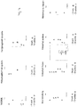
- the agricultural harvesting machine can be designed as an attachment for attachment to a tractor (not shown), for example in the form of a baler, the machine frame 2 of which by means of a bogey chassis 3 is supported on the ground.
- Fig. 1 shows only the left landing gear. It goes without saying, however, that the harvesting machine 1 can have such a chassis on the left and right.
- the machine frame 2 can be attached to the tractor, not shown, via an attachment device 4, for example in the form of a drawbar, and if it is designed as a baling press, it can carry a bale forming chamber 5 as a machine structure.
- the two bogey running gears 3 on the right and left side of the machine frame 2 are designed to be height-adjustable, as will be explained in more detail, wherein the running gears 3 can advantageously be individually and independently height-adjustable in order to be able to compensate for a slope when the harvesting machine 1 is moved in sloping terrain.
- the height of both chassis 3 can also be adjusted synchronously with one another or coordinated with one another, for example in order to gain more ground clearance when driving through a large depression or driving onto a ramp.
- each bogey chassis 3 comprises two wheel axles 8, 9, which are arranged in the manner of a twin axle at a short distance behind one another and are attached to a common axle carrier 10, which can extend approximately lying in the direction of travel.
- Said axle carrier 10 is pivotably mounted on a pivot axis carrier 12, which is connected to the machine frame 2, for example can be rigidly attached to it, about a pivot axis 11, which can extend horizontally across the direction of travel between the wheel axles 8 and 9.
- the named axle carrier 10 can thereby be luffed up and down about a horizontal transverse axis, that is to say the named pivot axis 11.
- said axle support 10 is divided and comprises two axle support parts 10a and 10b that can be pivoted or bent relative to one another, also around an articulated axis extending transversely to the direction of travel.
- the two axle support parts 10a and 10b can be jointly articulated on the aforementioned pivot axis 11, so that they can be bent relative to one another about the pivot axis 11 and can also be rocked up and down together about the named pivot axis 11.
- axle support parts 10a and 10b are mounted pivotable about two separate, parallel pivot axes 11 and 111 or rockable up and down in the manner of a rocker, with such separate pivot axes 11 and 111 advantageously close to one another and / or approximately can be arranged centrally between the wheel axles 8 and 9.
- At least two pressure medium actuators 13 and 14 are provided, which can be designed in particular as pressure medium cylinders or hydraulic cylinders. If necessary, however, other designs, for example in the form of hydraulic rotary motors, can also be considered.
- the at least two pressure medium actuators 13 and 14 can each be articulated on the one hand to one of the axle support parts 10a or 10b and on the other hand in each case to the pivoting axle support 12 or a support part connected to it or a support part fixed to the machine frame.
- the articulation points are selected in such a way that the pressure medium actuators 13 and 14 or their articulation points have a lever arm to the pivot axis 11 in order to be able to exert a torque on the axle carrier parts 10a and 10b.
- the two pressure medium actuators 13 and 14 can advantageously be arranged on the same side of the axle support 10, for example above the axle support 10.
- both pressure medium actuators 13 and 14 can be extended so that the two axle carrier parts 10a and 10b pivot relative to one another, as is shown in a comparison of FIG Figures 1 and 2 shows.
- the pressure medium actuators 13 and 14 can be adjusted in opposite directions, in particular one of the pressure medium actuators can retract and the other pressure medium actuator are extended.
- the pressure medium actuators 13 and 14 can be moved into a corresponding position and fixed there.
- a pressure medium control device 15 which can control the application of pressure medium, in particular hydraulic fluid, to pressure medium actuators 13 and 14 in various ways.
- Said pressure medium control device 15 can have a valve arrangement 16 with one or more switching valves and / or control valves in order to control the pressurization of the pressure chambers of the pressure medium actuators 13 and 14 and to be able to connect it to various pressure medium circuit modules, in particular optionally with a pressure source, a return to the tank and in short circuit with a pressure chamber of other pressure medium actuators.
- the mentioned pressure medium actuators 13 and 14 can be single acting pressure medium cylinders, especially under the assumption that the weight of the harvesting machine always tries to push the wheel axles 8 and 9 of the bogey chassis 3 towards the machine frame 2 or upwards.
- double-acting hydraulic cylinders can be used, in order to be able to control the adjusting movements in both directions, in particular also to be able to control the rocking of the axle carrier 10 in the bogey mode according to the displacement principle.
- the pressure medium actuators 13 and 14 can be short-circuited in terms of flow, so that pressure fluid displaced from one pressure medium actuator forces an adjusting movement of the other pressure medium actuator.
- the pressure medium actuators 13 and 14 can be directly connected to one another in terms of flow, so that pressure fluid can actually flow from one pressure medium actuator into the other pressure medium actuator and flow back.
- it would also be possible to interpose a compensation cylinder in the short-circuit connection so that pressure fluid displaced from a pressure medium actuator forces an adjusting movement of the compensation cylinder, which in turn displaces pressure fluid from the compensation cylinder and thus forces an adjusting movement of the other pressure medium actuator. Any differences in the displacement volume or in the cross-sectional area of the pressure chambers of the two pressure medium actuators 13 and 14 can be compensated for by means of such an interposed compensating cylinder.
- the pressure medium actuators 13 and 14 can be shut off or separated from a pressure source and a return, so that a linked, short-circuited floating state of the two pressure medium actuators and thus free rocking of the axle carrier 10 is established, in which the two axle carrier parts 10a and 10b in a predetermined Relative position to each other are frozen.
- the displacement volumes are not exactly the same or are not compensated by a compensating cylinder, when the axle carrier 10 is rocked also result in relative movements of the axle carrier parts to one another in the sense of a slight kinking or stretching.
- such relative movements are kept small or avoided entirely by suitable selection of the displacement volumes or their compensation.
- the pressure medium control device 15 can terminate the short-circuit mode mentioned and connect the pressure chambers of the pressure medium actuators 13 and 14 to a pressure source in order to both extend the pressure medium actuators 13 and 14 in order to pivot the axle carrier parts relative to one another, as can be seen from a comparison of FIG Figures 1 and 2 shows.
- the pressure medium control device 15 can also connect the pressure medium actuators 13 and 14 in a desired manner to the pressure source or the return of the system in order to move to a certain actuator position, and then the pressure medium actuators 13 and 14 to shut off or to lock in order to maintain the approached position.
- the setting device for setting the positions of the axle carrier parts can also have more than two pressure medium actuators.
- at least two further pressure medium actuators 17 and 18 can be provided, which can be coupled to the first-mentioned pressure medium actuators 13 and 14, in particular connected in series, so that an adjustment of the further Pressure medium actuators 17 and 18 induce an adjusting movement of the axle carrier parts 10a and 10b via the first-mentioned pressure medium actuators 13 and 14.
- the mentioned further pressure medium actuators 17 and 18 can advantageously also be arranged on the same side of the axle support 10 as the other pressure medium actuators 13 and 14, in particular above the axle support 10.
- These further pressure medium actuators 17 and 18 can be articulated on the one hand to the pivot axis support 12 or a carrier part connected to the machine frame 2 and, on the other hand, have an articulation point which is coupled to the other pressure medium actuators 13 and 14.
- the further pressure medium actuators 17 and 18 and the first-mentioned pressure medium actuators 13 and 14 can each be articulated to a transmitter 19, which is movably mounted and converts the adjusting movement of the further pressure medium actuators 17 and 18 into a movement of the pivot points of the first-mentioned pressure medium actuators 13 and 14 on the pivoting axis support.
- Said transmitter 19 can in particular be designed as a pivotable transmission lever which is pivotably mounted on the pivot axis carrier 12. In principle, however, it would also be conceivable to provide a displaceably mounted transmitter, for example in such a way that the pressure medium actuators coupled to one another are articulated on a common pivot pin which is guided displaceably in a groove.
- the further pressure medium actuators 17 and 18 are coupled to the first-mentioned pressure medium actuators 13 and 14 in pairs.
- a first pressure medium actuator 13 is coupled to a third pressure medium actuator 17, while the second pressure medium actuator 14 is coupled to the fourth pressure medium actuator 18, cf. Figures 3 and 4th .
- the pressure medium control device 15 can provide for the first and second pressure medium actuators 13 and 14 as well as for the third and fourth pressure medium actuators 17 and 18 in each case the operating modes described above, i.e. the rocker operating mode, the adjusting operating mode and the height adjustment mode and control the pressure medium actuators accordingly , whereby the pressure medium actuators 13 and 14 on the one hand and the pressure medium actuators 17 and 18 on the other hand can each be acted upon accordingly with pressure fluid individually or also in combination with one another.
- the operating modes described above i.e. the rocker operating mode, the adjusting operating mode and the height adjustment mode and control the pressure medium actuators accordingly , whereby the pressure medium actuators 13 and 14 on the one hand and the pressure medium actuators 17 and 18 on the other hand can each be acted upon accordingly with pressure fluid individually or also in combination with one another.
- the pressure medium control device 15 can also provide a special short-circuit connection between the pressure medium actuators, like this Fig. 3 shows.
- pairs of pressure medium actuators that are not coupled to one another via the aforementioned transmitter 19 can be short-circuited with one another.
- the first pressure medium actuator 13 can be short-circuited with the fourth pressure medium actuator 18, while the second pressure medium actuator 14 is short-circuited with the third pressure medium actuator 17, so that the displacement principle results in a rocking of the other axle support part when one axle support part is rocked down and vice versa.
- the pressure fluid displaced from the pressure medium actuator 13 or 14 when the one axle support part is rocked upwards forces an adjustment of the pressure medium actuator 17 or 18 short-circuited with it, which then leads via the respective transducer 19 to a corresponding adjusting movement of the other axle support part.
- Fig. 4 shows an example of a design of the pressure medium control device, which can advantageously have a plurality of switching valves in the form of multi-way switching valves.
- the multi-way switching valves mentioned can on the one hand Shut-off valves 21 for shutting off the respective pressure actuator from the pressure source and / or the return, and on the other hand switching valves 22 for switching the fluid connections between the pressure medium actuators and between a respective pressure medium actuator and the pressure source or the return.
- the multi-way switching valves 20 are advantageously designed, arranged and interconnected in such a way that the pressure medium actuators 13 and 14 or 17 and 18 can be optionally connected to a pressure source, a return or a short circuit in the above-mentioned manner, or separated from them, and also completely shut off in order to be able to hold an approached position.
- FIG. 5 and 6 Another embodiment is shown in Figures 5 and 6 shown, which with regard to the formation of the wheel axles 8 and 9, the axle carrier 10 or its axle carrier parts 10a and 10b and the pivotability to the machine frame about the pivot axis 11 and the pivotability to each other about the pivot axis 111 essentially the previously described embodiment according to the Figs. 1 to 4 corresponds to.
- the main difference to the previously described embodiments is the arrangement of the pressure medium actuators 13 and 14.
- a first pressure medium actuator 13 can be articulated on the one hand to one axle support part 10a and articulated to the other axle support part 10b, the points of articulation being spaced apart from the pivot axis 111 in order to have a lever arm with respect to said pivot axis 111 and the two axle support parts 10a and 10b to be able to pivot relative to each other.
- the other, second pressure medium actuator 14 is articulated on the one hand to one of the axle carriers 10b and on the other hand to the pivoting axis carrier 12 or a carrier fixed to the frame.
- the articulation point on the axle support side of the second pressure medium actuator 14 can be combined with the articulation point of the first pressure medium actuator 13 on this axle support 10a.
- the two pressure medium actuators 13 and 14 can also be arranged on the same side of the axle support 10 in this embodiment, in particular above the axle support 10.
- the first pressure medium actuator 13 which is articulated on both axle support parts 10a and 10b, can be used for height adjustment. By extending and retracting the first pressure medium actuator 13, the axle support parts 10a and 10b can be pivoted relative to one another, as was previously done by comparing FIG Figures 1 and 2 was made clear. In order to freeze a specific relative pivot position of the two axle carrier parts 10a and 10b, the pressure medium actuator 13 can be shut off or locked.
- the pivot position of the entire axle carrier 10 with respect to the pivot axis 11 can be controlled by the other pressure medium actuator 14. If the axle carrier 10 is to rock up and down in the bogey mode, the pressure medium actuator 14 can be shut off from the pressure source and the return and / or switched to the floating position so that it can move freely to and fro apart from the flow resistance.
- the pressure medium control device 15 can switch the pressure medium actuator 14 accordingly in the rocker operating mode, in particular connect the opposing pressure chambers of the pressure medium actuator 14 with one another if the pressure chambers are of the same size in terms of displacement, or they can also be connected to one another via a compensating cylinder or with a return flow and fluid supply connect that free movement is possible.
- the two pressure medium actuators 13 and 14 can advantageously each be designed as double cylinders, with two pistons mounted on a common piston rod, each slidably received in a separate cylinder and separating two pressure chambers from one another so that each of the separate cylinders is designed to be double-acting is.
- Such double cylinders can not only be executed according to the Figures 5 and 6 be useful, but also with the previously explained execution according to the Figures 1 to 4 Find use.
- the pressure medium control device 15 can include several multi-way switching valves, by means of which the pressure chambers of the pressure medium cylinders 13 and 14 can be pressurized from a pressure source, switched to the tank without pressure and connected to one another or "short-circuited" in order to fill one another in opposite directions or to empty.
- the pressure medium actuator 14 controlling the axle support to the machine frame can be depressurized with all chambers in order to allow the axle support to rock back and forth, while the pressure medium actuator 13 controlling the relative movement can be pressure-connected in at least two of the four chambers, in order to hold a central position in which the two axle support parts can assume a central position relative to one another, for example the 180 ° position shown in the figures.
- the pressure control device 15 can switch the valves in such a way that the pressure medium actuator 13 controlling the relative movement is pressurized so that it moves together and accordingly swivels the two axle carrier parts upwards.
- the other pressure medium actuator 14, which controls the absolute angular position, can be switched to be depressurized with a cylinder part and be pressurized with the other cylinder in the elongating chamber to take a center position. If, however, a slope compensation is to take place downhill, the pressure medium actuator 13 can be pressurized in its two lengthening chambers in order to extend the two axle support parts downwards to one another, while the absolute pressure medium cylinder 14 can be depressurized.
- the pressure medium control device 15 can also include a curve control mode in which the rear bogey axle 9 is relieved or raised.
- the pressure medium actuator 14 controlling the absolute angular position to the machine frame can be pressurized in order to maintain a certain position, while in the double cylinder 13, which controls the axle carrier parts to each other, at least one pressure chamber that causes retraction (relief mode) or both Chambers that cause retraction (lifting mode) can be pressurized, as shown in the lower row of partial views of the Figure 7 show the second and fourth representation.
- the rear bogey axle 8 is to be loaded, for example in a bale transfer mode, and the rear wheel is lowered accordingly, pressure can be applied to the relative cylinder 13 in both chambers, which cause an extension of the double cylinder, so that the rear axle carrier part 10a is moved downwards becomes.
- the front axle carrier part 10b is held in a predetermined position by freezing the pressure medium actuator 14, for example by applying pressure to an extending pressure chamber and an extending pressure chamber of the double cylinder, as shown in the third illustration in the lower row of partial views in FIG Figure 7 shows.
- the pressure medium actuator 14 In order to move to a certain position in the actuating mode of the pressure medium control device 15, the pressure medium actuator 14 is in principle connected to the pressure source or the return line until the desired position is reached, whereupon the pressure medium actuator 14 can be locked, for example by locking a switching valve.
- the other pressure medium actuator 13 can also be moved into a corresponding, desired position by connecting it to the pressure source and / or the return and then locked in order to force and maintain a certain position of the two wheel axles.
Landscapes
- Engineering & Computer Science (AREA)
- Mechanical Engineering (AREA)
- Life Sciences & Earth Sciences (AREA)
- Environmental Sciences (AREA)
- Vehicle Body Suspensions (AREA)
Claims (15)
- Moissonneuse et/ou machine de travail du sol agricole avec un châssis de machine (2), qui est soutenu sur le sol par au moins un train de roulement (3), qui présente deux essieux (8, 9) fixés respectivement sur un support d'essieu (10), qui est monté de manière à pouvoir pivoter autour d'un axe de pivotement (11) à la manière d'une bascule avec les essieux (8, 9) qui y sont fixés, dans laquelle ledit support d'essieu (10) est divisé, pour ajuster en hauteur le train de roulement (3), en au moins deux parties de support d'essieu (10a, 10b), qui peuvent pivoter l'une par rapport à l'autre, dans laquelle au moins deux actionneurs à moyen sous pression (13, 14) sont prévus pour régler la position relative des parties de support d'essieu (10a, 10b) l'une par rapport à l'autre, caractérisée en ce que les deux actionneurs à moyen sous pression (13, 14) sont prévus pour régler une position angulaire fixe pouvant être spécifiée du support d'essieu (10) par rapport à l'axe de pivotement (11) et pour bloquer la position angulaire réglée du support d'essieu (10) par rapport au châssis de machine (2).
- Moissonneuse et/ou machine de traitement du sol agricole selon la revendication précédente, dans laquelle lesdits au moins deux actionneurs à moyen sous pression (13, 14) sont articulés respectivement d'une part au niveau d'une des parties de support d'essieu (10a, 10b) et d'autre part au niveau d'un support d'axe de pivotement (12), par rapport auquel le train de roulement (3) peut être basculé, dans laquelle un dispositif de commande de moyen sous pression (15) est prévu pour piloter les actionneurs à moyen sous pression (13, 14), qui présentent un mode de fonctionnement de basculement, dans lequel les actionneurs à moyen sous pression (13, 14) sont court-circuités de telle manière que lors du relèvement par basculement d'une partie de support d'essieu, du fluide sous pression refoulé hors de l'actionneur à moyen sous pression relié à celle-ci produit de manière forcée un mouvement de réglage de l'autre actionneur à moyen sous pression pour abaisser par basculement la partie de support d'essieu reliée à celui-ci, et un mode de fonctionnement de réglage, dans lequel au moins un des actionneurs à moyen sous pression (13, 14) est relié à une source de pression et/ou à un conduit de retour et peut être déplacé et immobilisé dans une position prédéfinie.
- Moissonneuse et/ou machine de traitement du sol agricole selon la revendication précédente, dans laquelle dans ledit mode de fonctionnement de basculement, les deux vérins à moyen sous pression (13, 14) sont court-circuités de manière croisée de sorte qu'ils s'ajustent en sens inverse par le refoulement du moyen sous pression, dans laquelle une sortie d'un actionneur à moyen sous pression produit de manière forcée une rentrée de l'autre actionneur à moyen sous pression, et inversement, dans laquelle les actionneurs à moyen sous pression (13, 14) court-circuités dans le mode de fonctionnement de basculement ont des volumes de refoulement correspondant au moins approximativement les uns aux autres et/ou sont couplés indirectement les uns aux autres par l'intermédiaire d'un vérin de compensation de telle manière que les actionneurs à moyen sous pression court-circuités exécutent en valeur absolue au moins des mouvements de réglage correspondant sensiblement les uns aux autres.
- Moissonneuse et/ou machine de traitement du sol agricole selon l'une quelconque des revendications précédentes, dans laquelle le dispositif de commande de moyen sous pression (15) présente un ensemble formant soupape (16) pour relier au choix les actionneurs à moyen sous pression (13, 14) à une source de pression, à un conduit de retour et entre eux, dans laquelle l'ensemble formant soupape (16) est configuré en supplément pour fermer et/ou verrouiller les actionneurs à moyen sous pression (13, 14).
- Moissonneuse et/ou machine de traitement du sol agricole selon l'une quelconque des revendications précédentes, dans laquelle les au moins deux, de préférence tous les actionneurs à moyen sous pression (13, 14) sont disposés sur le même côté du support d'essieu (10), en particulier au-dessus du support d'essieu (10).
- Moissonneuse et/ou machine de traitement du sol agricole selon l'une quelconque des revendications précédentes, dans laquelle au moins deux autres actionneurs à moyen sous pression (17, 18) sont prévus de sorte qu'au total au moins quatre actionneurs à moyen sous pression (13, 14 ; 17, 18) sont couplés les uns aux autres par paires et sont branchés les uns après les autres respectivement de sorte que des mouvements de réglage des au moins deux autres actionneurs à moyen sous pression (17, 18) produisent de manière forcée des mouvements de réglage des actionneurs à moyen sous pression (13, 14) évoqués en premier et ainsi des mouvements de réglage des parties de support d'essieu (10a, 10b) rattachées à ceux-ci, dans laquelle lesdits autres actionneurs à moyen sous pression (17, 18) sont prévus en particulier pour ajuster des points d'articulation des actionneurs à moyen sous pression (13, 14) couplés à ceux-ci.
- Moissonneuse et/ou machine de traitement du sol agricole selon la revendication précédente, dans laquelle une paire de transmetteurs (19) montés de manière mobile au niveau du support d'axe de pivotement (12), en particulier des leviers transmetteurs pouvant pivoter sont prévus, dans laquelle d'une part un des actionneurs à moyen sous pression (13, 14) évoqués en premier d'une part et un des autres actionneurs à moyen sous pression (17, 18) sont articulés au niveau de chaque transmetteur (19).
- Moissonneuse et/ou machine de traitement du sol agricole selon l'une quelconque des deux revendications précédentes, dans laquelle dans le mode de fonctionnement de basculement du dispositif de commande de moyen sous pression (15), les autres actionneurs à moyen sous pression (17, 18) sont court-circuités par paire avec les actionneurs à moyen sous pression (13, 14) évoqués en premier, dans laquelle respectivement une paire d'actionneurs à moyen sous pression (13, 18 ; 14, 17), qui ne sont pas couplés les uns aux autres par l'intermédiaire du transmetteur (19), est court-circuitée.
- Moissonneuse et/ou machine de traitement du sol agricole selon la revendication 1, dans laquelle un des au moins deux actionneurs à moyen sous pression (13) est articulé au niveau de chacune des deux parties de support d'essieu (10a, 10b) de telle manière qu'un ajustement de l'actionneur à moyen sous pression (13) entraîne un pivotement des deux parties de support d'essieu (10a, 10b) l'une par rapport à l'autre et un deuxième des au moins deux actionneurs à moyen sous pression (14) est articulé d'une part au niveau d'une des deux parties de support d'essieu (10b) et d'autre part au niveau d'un support d'axe de pivotement (12) et/ou d'un support d'articulation solidaire du châssis de machine et ainsi est prévu pour régler la position angulaire du support d'essieu (10) par rapport à l'axe de pivotement (11) par rapport au châssis de machine (2).
- Moissonneuse et/ou machine de traitement du sol agricole selon la revendication précédente, dans laquelle le dispositif de commande de moyen sous pression (15) est configuré pour piloter les actionneurs à moyen sous pression (13, 14) pour commuter en position flottante dans le mode de fonctionnement de basculement l'actionneur à moyen sous pression (14), qui est articulé au niveau du support d'axe de pivotement (12) ou du support d'articulation solidaire du châssis de machine et pour déplacer dans une position prédéfinie et verrouiller les deux actionneurs à moyen sous pression (13, 14) dans le mode de fonctionnement de réglage.
- Moissonneuse et/ou machine de traitement du sol agricole selon l'une quelconque des revendications précédentes, dans laquelle les au moins deux actionneurs à moyen sous pression (13, 14) sont réalisés respectivement en tant que doubles vérins, dans laquelle en particulier une tige de piston (2) présente des pistons fixés au niveau de celle-ci, qui sont logés respectivement de manière à pouvoir coulisser dans des parties de vérin séparées et délimitent respectivement deux chambres de pression et/ou peuvent être soumis à une action respectivement sur deux côtés.
- Moissonneuse et/ou machine de traitement du sol agricole selon l'une quelconque des revendications précédentes, dans laquelle le dispositif de commande de moyen sous pression (15) présente un mode de fonctionnement en virage, dans lequel les aux moins deux actionneurs à moyen sous pression (13, 14) sont soumis à l'action d'une pression de telle manière qu'un des deux essieux (8, 9) du train de roulement (3), en particulier un essieu arrière (8), est déchargé et/ou relevé lors de la négociation de virages, dans laquelle le dispositif de commande de moyen sous pression (15) est réalisé de préférence pour fonctionner en fonction d'un signal de braquage dans un virage, qui indique un braquage d'un tracteur et/ou un angle de braquage d'une barre de direction et pour décharger un des deux essieux (8, 9).
- Moissonneuse et/ou machine de traitement du sol agricole selon l'une quelconque des revendications précédentes, dans laquelle le dispositif de commande de pression (15) présente un mode de fonctionnement de transfert de balles, dans lequel un essieu arrière (8) du train de roulement (3) est chargé et/ou un essieu avant (9) du train de roulement (3) est déchargé quand une balle agricole provenant d'une chambre de façonnage de balles est transmise à un enrouleur (7).
- Moissonneuse et/ou machine de traitement du sol agricole selon l'une quelconque des revendications précédentes, dans laquelle un dispositif de pesage est prévu pour détecter la charge, qui présente un système de détection de pression pour détecter la pression de moyen sous pression dans au moins un des actionneurs à moyen sous pression (13, 14), qui est prévu pour régler la position relative des parties de support d'essieu (10a, 10b) les unes par rapport aux autres et définit le chargement et/ou le poids de machine en fonction de la pression de moyen sous pression détectée.
- Moissonneuse et/ou machine de traitement du sol agricole selon l'une quelconque des revendications précédentes, dans laquelle au moins un des actionneurs à moyen sous pression (13, 14), qui est prévu pour régler la position relative des parties de support d'essieu les unes par rapport aux autres, est relié lors du mode de déplacement à un accumulateur de pression pour amortir des secousses liées à la chaussée.
Applications Claiming Priority (1)
| Application Number | Priority Date | Filing Date | Title |
|---|---|---|---|
| DE202017107372.6U DE202017107372U1 (de) | 2017-12-04 | 2017-12-04 | Landwirtschaftliche Ernte- und/oder Bodenbearbeitungsmaschine |
Publications (2)
| Publication Number | Publication Date |
|---|---|
| EP3491908A1 EP3491908A1 (fr) | 2019-06-05 |
| EP3491908B1 true EP3491908B1 (fr) | 2021-03-03 |
Family
ID=64604536
Family Applications (1)
| Application Number | Title | Priority Date | Filing Date |
|---|---|---|---|
| EP18210080.0A Active EP3491908B1 (fr) | 2017-12-04 | 2018-12-04 | Moissonneuse et/ou machine de traitement du sol agricole |
Country Status (2)
| Country | Link |
|---|---|
| EP (1) | EP3491908B1 (fr) |
| DE (1) | DE202017107372U1 (fr) |
Families Citing this family (2)
| Publication number | Priority date | Publication date | Assignee | Title |
|---|---|---|---|---|
| EP3845400A1 (fr) * | 2020-01-04 | 2021-07-07 | Trachsel Technik AG | Châssis pour remorque de véhicule et remorque de véhicule |
| WO2022229953A1 (fr) * | 2021-04-26 | 2022-11-03 | Ree Automotive Ltd. | Ensemble coin de véhicule à deux essieux |
Family Cites Families (5)
| Publication number | Priority date | Publication date | Assignee | Title |
|---|---|---|---|---|
| US2918292A (en) * | 1955-09-07 | 1959-12-22 | Scott Viner Company | Leveling device for mobile viner |
| US5794966A (en) * | 1996-02-05 | 1998-08-18 | Macleod; Kenneth J. | Vehicular suspension system |
| DE102015003695A1 (de) | 2015-03-20 | 2016-09-22 | Alois Pöttinger Maschinenfabrik Ges.m.b.H. | Ballenpresse |
| DE102015006221A1 (de) * | 2015-03-20 | 2016-09-22 | Alois Pöttinger Maschinenfabrik Ges.m.b.H. | Erntemaschine |
| PL3069600T3 (pl) * | 2015-03-20 | 2020-01-31 | Pöttinger Landtechnik Gmbh | Maszyna żniwna |
-
2017
- 2017-12-04 DE DE202017107372.6U patent/DE202017107372U1/de active Active
-
2018
- 2018-12-04 EP EP18210080.0A patent/EP3491908B1/fr active Active
Non-Patent Citations (1)
| Title |
|---|
| None * |
Also Published As
| Publication number | Publication date |
|---|---|
| EP3491908A1 (fr) | 2019-06-05 |
| DE202017107372U1 (de) | 2019-03-06 |
Similar Documents
| Publication | Publication Date | Title |
|---|---|---|
| EP2605632B1 (fr) | Machine agricole tractée dotée d'un rouleau | |
| EP1269825B1 (fr) | Agencement de roue porteuse pour une machine agricole | |
| EP4147563B1 (fr) | Moissonneuse dotée d'une tête réglable en hauteur | |
| DE2428917B2 (de) | Bodenbearbeitungsgeraet | |
| EP2281435A2 (fr) | Combinaison d'andain | |
| EP3491908B1 (fr) | Moissonneuse et/ou machine de traitement du sol agricole | |
| EP3302016B1 (fr) | Charrue semi-portée | |
| EP3646688B1 (fr) | Accessoire agricole | |
| EP2883722B1 (fr) | Moissonneuse automotrice dotée d'un couplage d'essieu hydraulique anti-roulis | |
| EP2883434B1 (fr) | Machine de traitement de sol | |
| WO2016110290A1 (fr) | Engin agricole à châssis de roulement supplémentaire | |
| EP3620037B1 (fr) | Appareil de travail de la terre | |
| DE102018209193A1 (de) | Landwirtschaftliches Bodenbearbeitungsgerät und Verfahren zu dessen Betrieb | |
| EP2710869A1 (fr) | Dispositif porte-outils frontal d'un véhicule de travail | |
| EP4049527B1 (fr) | Coupe-rubans | |
| EP4367997A1 (fr) | Andaineuse avec dispositif de ramassage | |
| EP1731009A1 (fr) | Charrue réversible avec un unité de commande de pression | |
| CA3049213A1 (fr) | Cadre et assemblage de mise a niveau d`un appareil agricole | |
| EP2769609A1 (fr) | Machine agricole tractée pouvant être attachée à un tracteur | |
| EP2371194B1 (fr) | Dispositif de répartition de semences et/ou d'engrais | |
| DE202010014789U1 (de) | Landwirtschaftliches Anbaugerät | |
| EP3354123B1 (fr) | Appareil de traitement du sol agricole | |
| EP4124221B1 (fr) | Machine agricole et combinaison de machines agricoles | |
| EP3698616A1 (fr) | Agencement de soc pourvu de rouleau de pression à régulation de la pression | |
| EP4122304B1 (fr) | Machine de travail agricole |
Legal Events
| Date | Code | Title | Description |
|---|---|---|---|
| PUAI | Public reference made under article 153(3) epc to a published international application that has entered the european phase |
Free format text: ORIGINAL CODE: 0009012 |
|
| STAA | Information on the status of an ep patent application or granted ep patent |
Free format text: STATUS: THE APPLICATION HAS BEEN PUBLISHED |
|
| AK | Designated contracting states |
Kind code of ref document: A1 Designated state(s): AL AT BE BG CH CY CZ DE DK EE ES FI FR GB GR HR HU IE IS IT LI LT LU LV MC MK MT NL NO PL PT RO RS SE SI SK SM TR |
|
| AX | Request for extension of the european patent |
Extension state: BA ME |
|
| STAA | Information on the status of an ep patent application or granted ep patent |
Free format text: STATUS: REQUEST FOR EXAMINATION WAS MADE |
|
| 17P | Request for examination filed |
Effective date: 20191128 |
|
| RBV | Designated contracting states (corrected) |
Designated state(s): AL AT BE BG CH CY CZ DE DK EE ES FI FR GB GR HR HU IE IS IT LI LT LU LV MC MK MT NL NO PL PT RO RS SE SI SK SM TR |
|
| GRAP | Despatch of communication of intention to grant a patent |
Free format text: ORIGINAL CODE: EPIDOSNIGR1 |
|
| RIC1 | Information provided on ipc code assigned before grant |
Ipc: A01D 75/28 20060101ALI20200820BHEP Ipc: A01F 15/08 20060101AFI20200820BHEP Ipc: B60G 21/02 20060101ALI20200820BHEP Ipc: B60G 5/06 20060101ALI20200820BHEP Ipc: B60G 21/067 20060101ALI20200820BHEP Ipc: A01F 15/07 20060101ALN20200820BHEP Ipc: B60G 21/00 20060101ALI20200820BHEP |
|
| STAA | Information on the status of an ep patent application or granted ep patent |
Free format text: STATUS: GRANT OF PATENT IS INTENDED |
|
| INTG | Intention to grant announced |
Effective date: 20200924 |
|
| GRAS | Grant fee paid |
Free format text: ORIGINAL CODE: EPIDOSNIGR3 |
|
| GRAA | (expected) grant |
Free format text: ORIGINAL CODE: 0009210 |
|
| STAA | Information on the status of an ep patent application or granted ep patent |
Free format text: STATUS: THE PATENT HAS BEEN GRANTED |
|
| AK | Designated contracting states |
Kind code of ref document: B1 Designated state(s): AL AT BE BG CH CY CZ DE DK EE ES FI FR GB GR HR HU IE IS IT LI LT LU LV MC MK MT NL NO PL PT RO RS SE SI SK SM TR |
|
| REG | Reference to a national code |
Ref country code: GB Ref legal event code: FG4D Free format text: NOT ENGLISH |
|
| REG | Reference to a national code |
Ref country code: CH Ref legal event code: EP Ref country code: AT Ref legal event code: REF Ref document number: 1366165 Country of ref document: AT Kind code of ref document: T Effective date: 20210315 |
|
| REG | Reference to a national code |
Ref country code: DE Ref legal event code: R096 Ref document number: 502018004121 Country of ref document: DE |
|
| REG | Reference to a national code |
Ref country code: IE Ref legal event code: FG4D Free format text: LANGUAGE OF EP DOCUMENT: GERMAN |
|
| REG | Reference to a national code |
Ref country code: NL Ref legal event code: FP |
|
| REG | Reference to a national code |
Ref country code: LT Ref legal event code: MG9D |
|
| PG25 | Lapsed in a contracting state [announced via postgrant information from national office to epo] |
Ref country code: LT Free format text: LAPSE BECAUSE OF FAILURE TO SUBMIT A TRANSLATION OF THE DESCRIPTION OR TO PAY THE FEE WITHIN THE PRESCRIBED TIME-LIMIT Effective date: 20210303 Ref country code: NO Free format text: LAPSE BECAUSE OF FAILURE TO SUBMIT A TRANSLATION OF THE DESCRIPTION OR TO PAY THE FEE WITHIN THE PRESCRIBED TIME-LIMIT Effective date: 20210603 Ref country code: BG Free format text: LAPSE BECAUSE OF FAILURE TO SUBMIT A TRANSLATION OF THE DESCRIPTION OR TO PAY THE FEE WITHIN THE PRESCRIBED TIME-LIMIT Effective date: 20210603 Ref country code: HR Free format text: LAPSE BECAUSE OF FAILURE TO SUBMIT A TRANSLATION OF THE DESCRIPTION OR TO PAY THE FEE WITHIN THE PRESCRIBED TIME-LIMIT Effective date: 20210303 Ref country code: FI Free format text: LAPSE BECAUSE OF FAILURE TO SUBMIT A TRANSLATION OF THE DESCRIPTION OR TO PAY THE FEE WITHIN THE PRESCRIBED TIME-LIMIT Effective date: 20210303 Ref country code: GR Free format text: LAPSE BECAUSE OF FAILURE TO SUBMIT A TRANSLATION OF THE DESCRIPTION OR TO PAY THE FEE WITHIN THE PRESCRIBED TIME-LIMIT Effective date: 20210604 |
|
| PG25 | Lapsed in a contracting state [announced via postgrant information from national office to epo] |
Ref country code: RS Free format text: LAPSE BECAUSE OF FAILURE TO SUBMIT A TRANSLATION OF THE DESCRIPTION OR TO PAY THE FEE WITHIN THE PRESCRIBED TIME-LIMIT Effective date: 20210303 Ref country code: LV Free format text: LAPSE BECAUSE OF FAILURE TO SUBMIT A TRANSLATION OF THE DESCRIPTION OR TO PAY THE FEE WITHIN THE PRESCRIBED TIME-LIMIT Effective date: 20210303 Ref country code: PL Free format text: LAPSE BECAUSE OF FAILURE TO SUBMIT A TRANSLATION OF THE DESCRIPTION OR TO PAY THE FEE WITHIN THE PRESCRIBED TIME-LIMIT Effective date: 20210303 Ref country code: SE Free format text: LAPSE BECAUSE OF FAILURE TO SUBMIT A TRANSLATION OF THE DESCRIPTION OR TO PAY THE FEE WITHIN THE PRESCRIBED TIME-LIMIT Effective date: 20210303 |
|
| PG25 | Lapsed in a contracting state [announced via postgrant information from national office to epo] |
Ref country code: EE Free format text: LAPSE BECAUSE OF FAILURE TO SUBMIT A TRANSLATION OF THE DESCRIPTION OR TO PAY THE FEE WITHIN THE PRESCRIBED TIME-LIMIT Effective date: 20210303 Ref country code: CZ Free format text: LAPSE BECAUSE OF FAILURE TO SUBMIT A TRANSLATION OF THE DESCRIPTION OR TO PAY THE FEE WITHIN THE PRESCRIBED TIME-LIMIT Effective date: 20210303 Ref country code: SM Free format text: LAPSE BECAUSE OF FAILURE TO SUBMIT A TRANSLATION OF THE DESCRIPTION OR TO PAY THE FEE WITHIN THE PRESCRIBED TIME-LIMIT Effective date: 20210303 |
|
| PG25 | Lapsed in a contracting state [announced via postgrant information from national office to epo] |
Ref country code: IS Free format text: LAPSE BECAUSE OF FAILURE TO SUBMIT A TRANSLATION OF THE DESCRIPTION OR TO PAY THE FEE WITHIN THE PRESCRIBED TIME-LIMIT Effective date: 20210703 Ref country code: SK Free format text: LAPSE BECAUSE OF FAILURE TO SUBMIT A TRANSLATION OF THE DESCRIPTION OR TO PAY THE FEE WITHIN THE PRESCRIBED TIME-LIMIT Effective date: 20210303 Ref country code: RO Free format text: LAPSE BECAUSE OF FAILURE TO SUBMIT A TRANSLATION OF THE DESCRIPTION OR TO PAY THE FEE WITHIN THE PRESCRIBED TIME-LIMIT Effective date: 20210303 Ref country code: PT Free format text: LAPSE BECAUSE OF FAILURE TO SUBMIT A TRANSLATION OF THE DESCRIPTION OR TO PAY THE FEE WITHIN THE PRESCRIBED TIME-LIMIT Effective date: 20210705 |
|
| REG | Reference to a national code |
Ref country code: DE Ref legal event code: R097 Ref document number: 502018004121 Country of ref document: DE |
|
| PLBE | No opposition filed within time limit |
Free format text: ORIGINAL CODE: 0009261 |
|
| STAA | Information on the status of an ep patent application or granted ep patent |
Free format text: STATUS: NO OPPOSITION FILED WITHIN TIME LIMIT |
|
| PG25 | Lapsed in a contracting state [announced via postgrant information from national office to epo] |
Ref country code: ES Free format text: LAPSE BECAUSE OF FAILURE TO SUBMIT A TRANSLATION OF THE DESCRIPTION OR TO PAY THE FEE WITHIN THE PRESCRIBED TIME-LIMIT Effective date: 20210303 Ref country code: DK Free format text: LAPSE BECAUSE OF FAILURE TO SUBMIT A TRANSLATION OF THE DESCRIPTION OR TO PAY THE FEE WITHIN THE PRESCRIBED TIME-LIMIT Effective date: 20210303 Ref country code: AL Free format text: LAPSE BECAUSE OF FAILURE TO SUBMIT A TRANSLATION OF THE DESCRIPTION OR TO PAY THE FEE WITHIN THE PRESCRIBED TIME-LIMIT Effective date: 20210303 |
|
| 26N | No opposition filed |
Effective date: 20211206 |
|
| PG25 | Lapsed in a contracting state [announced via postgrant information from national office to epo] |
Ref country code: SI Free format text: LAPSE BECAUSE OF FAILURE TO SUBMIT A TRANSLATION OF THE DESCRIPTION OR TO PAY THE FEE WITHIN THE PRESCRIBED TIME-LIMIT Effective date: 20210303 |
|
| PG25 | Lapsed in a contracting state [announced via postgrant information from national office to epo] |
Ref country code: IT Free format text: LAPSE BECAUSE OF FAILURE TO SUBMIT A TRANSLATION OF THE DESCRIPTION OR TO PAY THE FEE WITHIN THE PRESCRIBED TIME-LIMIT Effective date: 20210303 |
|
| PG25 | Lapsed in a contracting state [announced via postgrant information from national office to epo] |
Ref country code: IS Free format text: LAPSE BECAUSE OF FAILURE TO SUBMIT A TRANSLATION OF THE DESCRIPTION OR TO PAY THE FEE WITHIN THE PRESCRIBED TIME-LIMIT Effective date: 20210703 |
|
| PG25 | Lapsed in a contracting state [announced via postgrant information from national office to epo] |
Ref country code: MC Free format text: LAPSE BECAUSE OF FAILURE TO SUBMIT A TRANSLATION OF THE DESCRIPTION OR TO PAY THE FEE WITHIN THE PRESCRIBED TIME-LIMIT Effective date: 20210303 |
|
| REG | Reference to a national code |
Ref country code: CH Ref legal event code: PL |
|
| REG | Reference to a national code |
Ref country code: BE Ref legal event code: MM Effective date: 20211231 |
|
| PG25 | Lapsed in a contracting state [announced via postgrant information from national office to epo] |
Ref country code: LU Free format text: LAPSE BECAUSE OF NON-PAYMENT OF DUE FEES Effective date: 20211204 |
|
| PG25 | Lapsed in a contracting state [announced via postgrant information from national office to epo] |
Ref country code: BE Free format text: LAPSE BECAUSE OF NON-PAYMENT OF DUE FEES Effective date: 20211231 |
|
| PG25 | Lapsed in a contracting state [announced via postgrant information from national office to epo] |
Ref country code: LI Free format text: LAPSE BECAUSE OF NON-PAYMENT OF DUE FEES Effective date: 20211231 Ref country code: CH Free format text: LAPSE BECAUSE OF NON-PAYMENT OF DUE FEES Effective date: 20211231 |
|
| PG25 | Lapsed in a contracting state [announced via postgrant information from national office to epo] |
Ref country code: CY Free format text: LAPSE BECAUSE OF FAILURE TO SUBMIT A TRANSLATION OF THE DESCRIPTION OR TO PAY THE FEE WITHIN THE PRESCRIBED TIME-LIMIT Effective date: 20210303 |
|
| P01 | Opt-out of the competence of the unified patent court (upc) registered |
Effective date: 20230613 |
|
| PG25 | Lapsed in a contracting state [announced via postgrant information from national office to epo] |
Ref country code: HU Free format text: LAPSE BECAUSE OF FAILURE TO SUBMIT A TRANSLATION OF THE DESCRIPTION OR TO PAY THE FEE WITHIN THE PRESCRIBED TIME-LIMIT; INVALID AB INITIO Effective date: 20181204 |
|
| GBPC | Gb: european patent ceased through non-payment of renewal fee |
Effective date: 20221204 |
|
| PG25 | Lapsed in a contracting state [announced via postgrant information from national office to epo] |
Ref country code: GB Free format text: LAPSE BECAUSE OF NON-PAYMENT OF DUE FEES Effective date: 20221204 |
|
| PG25 | Lapsed in a contracting state [announced via postgrant information from national office to epo] |
Ref country code: MK Free format text: LAPSE BECAUSE OF FAILURE TO SUBMIT A TRANSLATION OF THE DESCRIPTION OR TO PAY THE FEE WITHIN THE PRESCRIBED TIME-LIMIT Effective date: 20210303 |
|
| PG25 | Lapsed in a contracting state [announced via postgrant information from national office to epo] |
Ref country code: TR Free format text: LAPSE BECAUSE OF FAILURE TO SUBMIT A TRANSLATION OF THE DESCRIPTION OR TO PAY THE FEE WITHIN THE PRESCRIBED TIME-LIMIT Effective date: 20210303 |
|
| PG25 | Lapsed in a contracting state [announced via postgrant information from national office to epo] |
Ref country code: MT Free format text: LAPSE BECAUSE OF FAILURE TO SUBMIT A TRANSLATION OF THE DESCRIPTION OR TO PAY THE FEE WITHIN THE PRESCRIBED TIME-LIMIT Effective date: 20210303 |
|
| REG | Reference to a national code |
Ref country code: AT Ref legal event code: MM01 Ref document number: 1366165 Country of ref document: AT Kind code of ref document: T Effective date: 20231204 |
|
| PG25 | Lapsed in a contracting state [announced via postgrant information from national office to epo] |
Ref country code: AT Free format text: LAPSE BECAUSE OF NON-PAYMENT OF DUE FEES Effective date: 20231204 |
|
| PGFP | Annual fee paid to national office [announced via postgrant information from national office to epo] |
Ref country code: DE Payment date: 20251216 Year of fee payment: 8 |
|
| PGFP | Annual fee paid to national office [announced via postgrant information from national office to epo] |
Ref country code: NL Payment date: 20251217 Year of fee payment: 8 Ref country code: FR Payment date: 20251229 Year of fee payment: 8 |
|
| PGFP | Annual fee paid to national office [announced via postgrant information from national office to epo] |
Ref country code: IE Payment date: 20251229 Year of fee payment: 8 |
|
| PGFP | Annual fee paid to national office [announced via postgrant information from national office to epo] |
Ref country code: AT Payment date: 20260410 Year of fee payment: 5 |