EP3491908B1 - Agricultural harvesting and/or soil working machine - Google Patents
Agricultural harvesting and/or soil working machine Download PDFInfo
- Publication number
- EP3491908B1 EP3491908B1 EP18210080.0A EP18210080A EP3491908B1 EP 3491908 B1 EP3491908 B1 EP 3491908B1 EP 18210080 A EP18210080 A EP 18210080A EP 3491908 B1 EP3491908 B1 EP 3491908B1
- Authority
- EP
- European Patent Office
- Prior art keywords
- pressure medium
- actuators
- pressure
- axle carrier
- axle
- Prior art date
- Legal status (The legal status is an assumption and is not a legal conclusion. Google has not performed a legal analysis and makes no representation as to the accuracy of the status listed.)
- Active
Links
Images
Classifications
-
- A—HUMAN NECESSITIES
- A01—AGRICULTURE; FORESTRY; ANIMAL HUSBANDRY; HUNTING; TRAPPING; FISHING
- A01D—HARVESTING; MOWING
- A01D75/00—Accessories for harvesters or mowers
- A01D75/28—Control mechanisms for harvesters or mowers when moving on slopes; Devices preventing lateral pull
-
- A—HUMAN NECESSITIES
- A01—AGRICULTURE; FORESTRY; ANIMAL HUSBANDRY; HUNTING; TRAPPING; FISHING
- A01F—PROCESSING OF HARVESTED PRODUCE; HAY OR STRAW PRESSES; DEVICES FOR STORING AGRICULTURAL OR HORTICULTURAL PRODUCE
- A01F15/00—Baling presses for straw, hay or the like
- A01F15/08—Details
-
- B—PERFORMING OPERATIONS; TRANSPORTING
- B60—VEHICLES IN GENERAL
- B60G—VEHICLE SUSPENSION ARRANGEMENTS
- B60G21/00—Interconnection systems for two or more resiliently-suspended wheels, e.g. for stabilising a vehicle body with respect to acceleration, deceleration or centrifugal forces
- B60G21/002—Interconnection systems for two or more resiliently-suspended wheels, e.g. for stabilising a vehicle body with respect to acceleration, deceleration or centrifugal forces longitudinally
-
- B—PERFORMING OPERATIONS; TRANSPORTING
- B60—VEHICLES IN GENERAL
- B60G—VEHICLE SUSPENSION ARRANGEMENTS
- B60G21/00—Interconnection systems for two or more resiliently-suspended wheels, e.g. for stabilising a vehicle body with respect to acceleration, deceleration or centrifugal forces
- B60G21/02—Interconnection systems for two or more resiliently-suspended wheels, e.g. for stabilising a vehicle body with respect to acceleration, deceleration or centrifugal forces permanently interconnected
- B60G21/023—Interconnection systems for two or more resiliently-suspended wheels, e.g. for stabilising a vehicle body with respect to acceleration, deceleration or centrifugal forces permanently interconnected longitudinally
-
- B—PERFORMING OPERATIONS; TRANSPORTING
- B60—VEHICLES IN GENERAL
- B60G—VEHICLE SUSPENSION ARRANGEMENTS
- B60G21/00—Interconnection systems for two or more resiliently-suspended wheels, e.g. for stabilising a vehicle body with respect to acceleration, deceleration or centrifugal forces
- B60G21/02—Interconnection systems for two or more resiliently-suspended wheels, e.g. for stabilising a vehicle body with respect to acceleration, deceleration or centrifugal forces permanently interconnected
- B60G21/06—Interconnection systems for two or more resiliently-suspended wheels, e.g. for stabilising a vehicle body with respect to acceleration, deceleration or centrifugal forces permanently interconnected fluid
- B60G21/067—Interconnection systems for two or more resiliently-suspended wheels, e.g. for stabilising a vehicle body with respect to acceleration, deceleration or centrifugal forces permanently interconnected fluid between wheels on different axles on the same side of the vehicle, i.e. the left or the right side
-
- B—PERFORMING OPERATIONS; TRANSPORTING
- B60—VEHICLES IN GENERAL
- B60G—VEHICLE SUSPENSION ARRANGEMENTS
- B60G5/00—Resilient suspensions for a set of tandem wheels or axles having interrelated movements
- B60G5/04—Resilient suspensions for a set of tandem wheels or axles having interrelated movements with two or more pivoted arms, the movements of which are resiliently interrelated, e.g. the arms being rigid
- B60G5/06—Resilient suspensions for a set of tandem wheels or axles having interrelated movements with two or more pivoted arms, the movements of which are resiliently interrelated, e.g. the arms being rigid the arms turning on a common pivot, e.g. being rigid
-
- A—HUMAN NECESSITIES
- A01—AGRICULTURE; FORESTRY; ANIMAL HUSBANDRY; HUNTING; TRAPPING; FISHING
- A01F—PROCESSING OF HARVESTED PRODUCE; HAY OR STRAW PRESSES; DEVICES FOR STORING AGRICULTURAL OR HORTICULTURAL PRODUCE
- A01F15/00—Baling presses for straw, hay or the like
- A01F15/07—Rotobalers, i.e. machines for forming cylindrical bales by winding and pressing
- A01F15/071—Wrapping devices
- A01F2015/0735—Combined machines that include a press bale and a wrapping device in a further step, e.g. turning table, not in the same closed pressing chamber
-
- B—PERFORMING OPERATIONS; TRANSPORTING
- B60—VEHICLES IN GENERAL
- B60G—VEHICLE SUSPENSION ARRANGEMENTS
- B60G2200/00—Indexing codes relating to suspension types
- B60G2200/30—Rigid axle suspensions
- B60G2200/318—Rigid axle suspensions two or more axles being mounted on a longitudinal rocking or walking beam
-
- B—PERFORMING OPERATIONS; TRANSPORTING
- B60—VEHICLES IN GENERAL
- B60G—VEHICLE SUSPENSION ARRANGEMENTS
- B60G2204/00—Indexing codes related to suspensions per se or to auxiliary parts
- B60G2204/80—Interactive suspensions; arrangement affecting more than one suspension unit
- B60G2204/81—Interactive suspensions; arrangement affecting more than one suspension unit front and rear unit
-
- B—PERFORMING OPERATIONS; TRANSPORTING
- B60—VEHICLES IN GENERAL
- B60G—VEHICLE SUSPENSION ARRANGEMENTS
- B60G2204/00—Indexing codes related to suspensions per se or to auxiliary parts
- B60G2204/80—Interactive suspensions; arrangement affecting more than one suspension unit
- B60G2204/83—Type of interconnection
- B60G2204/8304—Type of interconnection using a fluid
-
- B—PERFORMING OPERATIONS; TRANSPORTING
- B60—VEHICLES IN GENERAL
- B60G—VEHICLE SUSPENSION ARRANGEMENTS
- B60G2206/00—Indexing codes related to the manufacturing of suspensions: constructional features, the materials used, procedures or tools
- B60G2206/01—Constructional features of suspension elements, e.g. arms, dampers, springs
- B60G2206/011—Modular constructions
- B60G2206/0112—Bogies for heavy vehicles
-
- B—PERFORMING OPERATIONS; TRANSPORTING
- B60—VEHICLES IN GENERAL
- B60G—VEHICLE SUSPENSION ARRANGEMENTS
- B60G2300/00—Indexing codes relating to the type of vehicle
- B60G2300/04—Trailers
-
- B—PERFORMING OPERATIONS; TRANSPORTING
- B60—VEHICLES IN GENERAL
- B60G—VEHICLE SUSPENSION ARRANGEMENTS
- B60G2300/00—Indexing codes relating to the type of vehicle
- B60G2300/04—Trailers
- B60G2300/042—Semi-trailers
-
- B—PERFORMING OPERATIONS; TRANSPORTING
- B60—VEHICLES IN GENERAL
- B60G—VEHICLE SUSPENSION ARRANGEMENTS
- B60G2300/00—Indexing codes relating to the type of vehicle
- B60G2300/08—Agricultural vehicles
-
- B—PERFORMING OPERATIONS; TRANSPORTING
- B60—VEHICLES IN GENERAL
- B60G—VEHICLE SUSPENSION ARRANGEMENTS
- B60G2500/00—Indexing codes relating to the regulated action or device
- B60G2500/30—Height or ground clearance
Definitions
- the present invention relates to an agricultural harvesting and / or soil cultivation machine with a machine frame which is supported on the ground by at least one bogey chassis, which has two wheel axles each attached to an axle carrier, which together with the wheel axles in the manner of a rocker around a pivot axis is pivotably mounted, wherein the axle support for height adjustment of the bogey chassis is divided into at least two axle support parts which are pivotable relative to one another.
- Agricultural harvesting and / or soil cultivation machines such as balers or loading wagons with a pick-up device for picking up crops from the ground are often equipped with bogey chassis, as such bogey chassis on the one hand enable favorable ground adaptation with even load distribution on both axles on the one hand, even on undulating terrain, and on the other allows others to adjust the height of the chassis in a simple manner.
- the height adjustment in the left and right lanes can also be done independently or individually, so that slope compensation can be achieved in a simple manner, i.e. when driving parallel on the slope transversely to the slope, the lower bogey chassis can be higher and / or the uphill chassis deeper be placed so that the machine structure is approximately horizontal or at least less inclined and a certain inclination compensation is achieved.
- this can be useful in order to facilitate the transfer of a completely wrapped bale from the baling chamber to the wrapping device.
- this can be useful in order to achieve an even distribution of forage when distributing the harvested material in the storage space, for example by switching on the scraper floor.
- Such bogey chassis can also be useful on other types of agricultural machinery, for example on seed drills, tillage equipment such as plows, cultivators, harrows or tillage combinations, as well as haymaking machines such as rakes and tedders or other agricultural harvesting or tillage machines, especially if they are used as attachments for cultivation a tractor are trained.
- tillage equipment such as plows, cultivators, harrows or tillage combinations
- haymaking machines such as rakes and tedders or other agricultural harvesting or tillage machines, especially if they are used as attachments for cultivation a tractor are trained.
- the writings EP 3 069 598 A1 , EP 30 69 600 A1 and DE 10 2015 006 221 A1 each show, for example, a baler, the machine frame of which is supported on the ground by a bogey chassis, the rocker-like axle carrier on which the two wheel axles are attached is designed in a split manner and has two mutually pivotable legs in order to be able to adjust the height of the bogey chassis.
- the two legs of the split axle carrier are hinged to a common pivot axis and connected to one another by a setting actuator, so that different angular positions of the axle carrier legs can be set to one another by lengthening or shortening the setting actuator, so that the bogey chassis can be adjusted in height.
- axle support legs When the axle support legs are frozen relative to one another, the entire, then rigid, axle support can rock up and down together with the actuating actuator about the pivot axis in order to implement the bogey driving mode in a manner known per se.
- the writing shows a similar bogey chassis for a bean harvester US 2918292 A .
- such a bogey chassis can also be a hindrance or the mentioned height adjustment can not be sufficient.
- the machine can unintentionally sag as a whole if one of the two wheel axles has driven over the slope edge onto the sloping flank, although the other wheel axle itself would still be placed on the upper section of the slope edge.
- driving over smaller grooves or smaller transverse channels can also lead to restless driving behavior with vertical impacts or vibrations on the machine structure.
- the present invention is based on the object of creating an improved agricultural harvesting and / or soil cultivating machine which avoids the disadvantages of the prior art and further develops the latter in an advantageous manner.
- the chassis supporting the machine frame on the ground is to be further developed in order to maintain the advantages of a bogey chassis, but to eliminate or at least weaken its disadvantages, whereby the chassis should be as simple as possible with few parts despite the height adjustability.
- a Setting device for the variable setting of a fixed, predeterminable angular position of the axle carrier overall with respect to the pivot axis to be provided in order to be able to predetermine a specific pivot position of the axle carrier in the sense of an absolute angular position of the axle carrier relative to the machine frame.
- at least two pressure medium actuators are provided for setting the relative position of the axle support parts to one another and for setting the angular position of the axle support with respect to the pivot axis relative to the machine frame.
- the at least two pressure medium actuators are arranged and designed in such a way that, on the one hand, they enable normal bogey driving with wheel axles rocking up and down in opposite directions, but on the other hand they also enable driving with, so to speak, frozen pivot position of the axle carrier or the fixing of at least one axle carrier part with respect to the pivot axis , and can also adjust the height of the bogey chassis.
- said at least two pressure medium actuators can each be articulated on the one hand to one of the axle support parts and on the other hand to a pivoting axle support, with respect to which the bogey chassis can be luffed.
- Said swivel axle carrier can be, for example, a chassis suspension carrier rigidly connected to the machine frame, but possibly also an adjustable wheel or axle suspension element, with respect to which the axle carrier of the bogey chassis can be pivoted or rocked up and down with both axle carrier parts.
- a pressure medium control device can be provided in a further development of the invention to control the at least two pressure medium actuators mentioned, which provides different operating modes for the pressure medium actuators in which the pressure medium application in is controlled in different ways.
- the said pressure medium control device can have a rocker operating mode in which the pressure medium actuators are short-circuited with one another so that the pressure medium actuators push pressure medium back and forth or pump back and forth according to the displacement principle if corresponding movements of the Pressure medium actuators comes.
- the pressure medium cylinders can be shut off from a pressure medium source and / or from a return to the tank of the pressure medium supply, so that pressure medium is only circulated or displaced back and forth internally between the pressure medium actuators.
- the mentioned pressure medium actuators can be short-circuited in such a way that when one axle carrier part is rocked up or down, the pressure fluid displaced from the associated pressure medium actuator forces an adjusting movement of the other pressure medium actuator, which leads to a counter-rocking down or up of the other axle carrier part connected to the mentioned other pressure medium actuator.
- the pressure medium actuators are thus short-circuited to one another in such a way that they mutually force adjusting movements which lead to pivoting or rocking of the axle carrier parts in the same direction of rotation.
- these can be counter-rotating or synchronous adjusting movements of the pressure actuators.
- two pressure medium cylinders are provided as pressure medium actuators, which are arranged on the same side of the axle support or are articulated on the same side of the pivot axis on the swivel axle support, so that one pressure medium cylinder has to lengthen and the other pressure medium cylinder has to shorten by the axle support overall bogey-like rocking or swiveling one wheel axle upwards and the other wheel axle downwards, the two hydraulic cylinders can be short-circuited crosswise so that pressure fluid that is displaced from one cylinder when it is shortened lengthen the other cylinder enforces.
- the mentioned pressure medium cylinders are arranged on different sides of the axle support or articulated on opposite sides of the pivot axis, for example in a z-like configuration or in a configuration with a cylinder above and a cylinder below the axle support, so that both pressure medium cylinders lengthen by a
- the pressure medium actuators can also be short-circuited to one another in such a way that synchronous adjusting movements result.
- the pressure fluid displaced when one cylinder is shortened also forces a shortening of the other pressure medium cylinder
- the pressure fluid displaced when one pressure medium cylinder is lengthened also forces the other pressure medium cylinder to be lengthened.
- the aforementioned pressure medium control device advantageously also has an actuating mode in which at least one of the aforementioned pressure medium actuators is connected to a pressure source and / or a return in order to move to a predetermined pivot position by applying pressure medium and / or releasing pressure medium, and then in the predetermined position can be determined, for example, in that at least one pressure chamber of the pressure medium actuator is shut off by means of a shut-off valve.
- the pressure medium control device provides an active setting and determination of a predetermined position of the pressure medium actuator so that the axle carrier part connected to it can be determined in an absolute angular position, since the said actuating actuator is as above explains a point of articulation on the pivot axis support or an articulation part connected therewith.
- the pressure medium control device can move and determine both pressure medium actuators by connecting to the pressure source and / or the return in a predetermined absolute angular position relative to the machine frame in the said actuating operating mode, so that the position of both wheel axles of the bogey chassis can be adjusted and determined.
- said pressure medium control device can furthermore have a height adjustment mode in which the two pressure medium actuators are each connected to the mentioned pressure source, possibly also with two separate pressure sources - or a return - possibly also with two separate returns - to adjust the relative angular position of the two Adjust the axle support parts relative to each other and thus adjust the height of the bogey chassis.
- Said pressure medium control device can advantageously comprise a valve device which has various switching positions in which the pressure medium actuators can be short-circuited with one another in the manner described above and optionally connected to a pressure source or a return.
- Said valve device can have a plurality of shut-off valves and / or multi-way valves.
- the mentioned pressure medium actuators and their pressure medium control device are advantageously designed in such a way that the pressure medium actuators move at least approximately synchronized with one another in the mentioned short-circuit or rocker operating mode, so that the axle carrier legs controlled by the pressure medium actuators move at least approximately synchronously with one another, i.e. by approximately the same pivot angle pivot.
- Complete synchronization of the axle support parts is not necessary, but it can be provided so that the axle support legs are actually frozen rigidly to one another in the rocker operating mode and only turn around the pivot axis can rock up and down without performing relative movements to each other.
- the pressure medium actuators can have mutually corresponding displacement volumes so that the adjusting movement of the other pressure medium actuator forced by the displaced pressure fluid of one pressure medium actuator is at least approximately the same in terms of magnitude. If the displacement volumes of the two pressure medium actuators are approximately the same, the pressure medium actuators can be short-circuited directly to one another.
- a compensating cylinder can also be provided in the short-circuit circuit of the two pressure medium actuators, which compensates for different displacement volumes or at least approximates them to a certain extent.
- Such a compensating cylinder can have pressure chambers of different sizes, wherein a pressure chamber with a larger cross section can be connected to the pressure medium actuator with a larger displacement volume and the pressure chamber with a smaller cross-sectional area can be connected to the pressure medium actuator with a smaller displacement volume.
- said pressure medium actuators can be short-circuited with one another in the short-circuit mode in order to carry out movements in opposite directions, or they can be short-circuited parallel to one another in order to carry out movements in the same direction.
- pressure cylinders can be arranged above the axle carrier and have a pivot point on the same side of the pivot axis so that they move in opposite directions, i.e. one pressure cylinder has to lengthen and the other pressure cylinder has to shorten in order to achieve a rocking bogey operation enable.
- said cross-over short circuit can be provided.
- more than two pressure medium actuators can also be provided in a further development of the invention.
- two further pressure medium actuators can be provided, which can be coupled to the two first-mentioned pressure medium actuators in pairs, in particular connected in series, so that the actuating movement of the further pressure medium actuators is transmitted to the respective axle carrier via the first pressure medium actuators.
- a first pressure medium actuator is coupled to a third pressure medium actuator and a second pressure medium actuator is coupled to a fourth pressure medium actuator
- the actuating movement of the third pressure medium actuator can be transmitted to the axle carrier connected to it by the first pressure medium actuator, while an actuating movement of the fourth pressure medium actuator is transmitted to the associated axle carrier is transmitted.
- the two further pressure medium actuators - the third and fourth pressure medium actuators in the example described above - can be provided to adjust the articulation points of the first two pressure medium actuators - that is, the first and second pressure medium actuators - on the pivot axle support. If the third and fourth pressure medium actuators are retracted or extended, the articulation points of the first and second pressure medium actuators move on the said pivoting kachong.
- the four pressure medium actuators mentioned can be coupled to one another in pairs via transmitters, for example in the form of pivot levers, the pivot levers mentioned each being pivotable on the pivot axis support can be stored.
- a very compact design can be achieved in which the third and fourth pressure medium actuators can be arranged independently of the desired adjustment direction for the articulation points of the first and second pressure medium actuators.
- a step-up or step-down effect can also be achieved via the pivot levers mentioned, which enables the desired adjustment movement with a limited adjustment path of the pressure medium actuators and / or a limited size of the pressure medium actuators.
- the pressure medium control device in its rocker operating mode can in itself short-circuit the first and second pressure medium actuators to one another as described above, whereby the third and fourth pressure medium actuators can be blocked or determined so that the bogey or rocker operation can only be achieved by moving the first and second pressure cylinder.
- the pressure medium control device in the rocker operating mode can, however, advantageously also provide a short circuit between the pressure medium cylinders, which also includes the additional third and fourth pressure medium actuators.
- the two first-mentioned pressure medium actuators, which are articulated to the axle support parts, can each be short-circuited with the additional pressure medium actuator, with which they are not connected in series and are not coupled through the said transducer.
- the first pressure medium cylinder - possibly via the pivot lever described - is coupled to the third pressure medium actuator and connected in series in the aforementioned manner, said first pressure medium cylinder can be short-circuited with the fourth pressure medium cylinder, which can be short-circuited with the second pressure medium actuator - if necessary via a further pivot lever - is coupled.
- the named second pressure medium cylinder can then be short-circuited with the aforementioned third pressure medium actuator.
- movements of the first and second pressure medium actuators force corresponding movements of the third and fourth pressure medium actuators, so that all four mentioned pressure medium actuators are adjusted when the axle carrier as a whole, i.e. with both axle carrier parts, rocks up and down about the pivot axis in bogey mode.
- the first-mentioned at least two pressure medium actuators do not have to be articulated in the manner described above, on the one hand, on an axle support half and, on the other hand, on the pivoting axle support or another part fixed to the machine frame.
- the two pressure medium actuators can also have separate or different functional tasks and be articulated differently.
- the one pressure medium actuator can be provided for the height adjustment of the bogey chassis, in particular arranged and designed to pivot the two axle support parts relative to one another, while the other of the at least two pressure medium actuators can be provided to set the absolute angular position of the axle support relative to the machine frame and / or determine.
- one of the two pressure medium actuators can have articulation points on different axle support parts, so that an adjustment of the pressure medium actuator causes the two axle support parts to pivot relative to one another.
- the other of the two pressure medium actuators can on the one hand be articulated on one of the two axle support parts and on the other hand have an articulation point fixed to the machine frame or be articulated on the previously mentioned swivel axle support or an element connected to it, with respect to which the axle support has to rotate when bogey rocking.
- the pressure medium actuators can be individually adapted to their respective task and, in particular, can also be designed differently from one another.
- the pressure medium actuator which adjusts the two axle parts to one another can have a different travel and / or a different travel path have a different piston diameter than the pressure medium actuator, which sets the angular position of the axle parts relative to the machine frame.
- the pressure medium control device for the two pressure medium actuators can also be designed differently, in particular comprise different valve arrangements by means of which the respective pressure medium actuator can be controlled.
- the aforementioned pressure medium control device can, in its rocker operating mode, block the pressure medium actuator, which has articulation points on both axle support parts and is responsible for the height adjustment, for example by locking it to make it unchangeable in length and thus freeze the relative position of the two axle support parts to one another, and Switch the other pressure medium actuator, which has an articulation point fixed to the machine frame, into the floating position.
- said pressure medium control device in its setting mode of operation can move said pressure medium actuator with an articulation point fixed to the machine frame by applying pressure or connecting it to the return line into a predetermined operating position and determine it, with the other pressure medium actuator remaining locked with articulation points on both axle parts or also moving into another position and can then be locked. If necessary, it would also be conceivable to switch the said pressure medium actuator, which has articulation points on both axle support parts, into the floating position, in which case the entire weight of the other axle support part would then be intercepted, which is locked by the pressure medium actuator with the articulation point fixed to the machine frame.
- the pressure control device can include a cornering operating mode in which one of the two wheel axles is relieved and / or raised while the other wheel axle is loaded by the weight of the machine if necessary to be carried together with the support force of the drawbar.
- the rear of the two bogey wheel axles can be relieved and / or raised, which can be done, for example, in that the pressure control device locks and / or applies sufficient pressure to the pressure medium actuator that supports one of the axle support parts, in particular the front axle support part, on the machine frame applied, while the pressure medium actuator, which can adjust the two axle carrier parts relative to one another, is brought into the floating position or is actively pressurized in order to even slightly raise the wheel axle.
- the pressure medium control device can work as a function of a cornering signal, wherein such a cornering signal can be obtained or provided in different ways.
- a cornering signal can be obtained or provided in different ways.
- this can be a steering angle signal from the tractor that indicates the steering angle of the tractor.
- the deflection of the drawbar of the attachment towards the tractor or attachment can be measured and used as a cornering signal, depending on which one of the bogey axles can be relieved and / or raised.
- such an unequal wheel axle load can also be useful in other operating situations and can be provided by the pressure control device.
- the attachment is, for example, a baling press
- it can make sense to load the rear bogey axle more heavily and / or to relieve the front bogey axle so that the weight of the bale is relieved for the bale transfer from the bale forming chamber to the winder following in the direction of travel is more strongly supported during the transfer by the rear wheel axle and / or wheel axle closer to the bale. This means that shocks that occur when the bale is transferred to the wrapper can be better absorbed and kept away from the tractor.
- the pressure control device can, for example, have a bale transfer operating mode that controls the load distribution in the above-mentioned manner Controls wheel axles of the bogey chassis differently, wherein the pressure control device can work as a function of a bale transfer signal.
- a bale transfer signal can also be obtained or provided in various ways.
- the opening of the tailgate of the bale forming chamber can be monitored by sensors and used as a transfer signal, but the movement of the bale out of the forming chamber onto the winder itself and / or a movement of a bale ejector can be monitored by sensors in order to signal to the pressure control device that the bale is transferred to the wrapper and the axle load distribution is controlled accordingly.
- the aforementioned "machine frame fixed" articulation point does not actually have to be fixed and immovable or immobile, but merely means the articulation point of the pressure medium actuator, which is located on the machine frame side and is not attached to one of the axle support parts. If further pressure medium actuators are provided in the aforementioned manner, the articulation point of the first or second pressure medium actuator fixed to the machine frame can lie, for example, on said pivot lever, which is pivotably mounted on the pivot axis support and is coupled to said further pressure medium actuator.
- the agricultural machine can be provided with a weighing system that detects the pressure in at least one of the named pressure medium actuators of the bogey chassis and, depending on the detected pressure, provides a weight signal that characterizes the load and / or the weight of the machine.
- the pressure in the corresponding, at least one pressure medium actuator of the bogey chassis can be detected directly in a corresponding pressure chamber of the cylinder, but also in a corresponding supply line.
- the above-mentioned weighing system for determining weight can, in addition to the pressure from the pressure medium actuators of the bogey chassis, also detect a load on the drawbar of the machine and take into account in order to also take into account the weight component supported by the drawbar.
- the pressure medium actuators are arranged in accordance with the division of functions described above in such a way that one of the pressure medium actuators adjusts the axle support parts relative to one another and the other pressure medium actuator sets the absolute angular position to the machine frame, only the pressure of the actuator that controls the relative position of the axle support parts can easily be used for the Weighing can be recorded and used. It can be useful to switch the pressure control device of the weighing system to a weighing operating mode in which the said pressure medium actuator for the absolute angular position is in the floating position so that the axle load is evenly distributed, and / or the pressure medium actuator for the relative position is in a predetermined one Position to move in order to set a predetermined axle beam geometry with predetermined lever arms for the pressure measurement.
- the pressure in both pressure medium actuators can be used, which is set when the two pressure medium actuators are switched to the floating position, i.e. can move in opposite directions to move the axle supports to hold a fixed position relative to each other, but allow a swing of the axle beam as a whole.
- At least one of the pressure medium actuators in particular the pressure medium actuator controlling the relative position of the two axle carrier parts, can be connected to a pressure accumulator, which pressure accumulator can work as a damper to dampen shocks absorbed from the ground during driving.
- a pressure accumulator By means of a flow connection with a pressure accumulator, the two axle support parts can carry out compensatory movements relative to one another, if from shocks come from the road.
- a pressure accumulator can also be useful for the pressure cylinder, which specifies the absolute angular position in order to allow compensating movements in a corresponding manner when road bumps occur, for example in a phase of unequal axle load distribution.
- the pressure medium actuators can in principle be designed in various ways.
- double cylinders in particular can be provided, which can have two pistons on a common piston rod, which are each slidably received in separate cylinders.
- each of the cylinders can be designed to be double-acting, so that each of the two pistons can be displaced in its respective cylinder in both directions and pressure can be applied.
- Such a double cylinder can be useful in the various arrangements of the pressure medium actuators.
- the pressure medium cylinder controlling the relative movement of the two axle carrier parts and / or the pressure medium cylinder controlling the absolute angular position to the machine frame can be designed as a double cylinder in the manner mentioned.
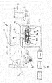
- the agricultural harvesting machine can be designed as an attachment for attachment to a tractor (not shown), for example in the form of a baler, the machine frame 2 of which by means of a bogey chassis 3 is supported on the ground.
- Fig. 1 shows only the left landing gear. It goes without saying, however, that the harvesting machine 1 can have such a chassis on the left and right.
- the machine frame 2 can be attached to the tractor, not shown, via an attachment device 4, for example in the form of a drawbar, and if it is designed as a baling press, it can carry a bale forming chamber 5 as a machine structure.
- the two bogey running gears 3 on the right and left side of the machine frame 2 are designed to be height-adjustable, as will be explained in more detail, wherein the running gears 3 can advantageously be individually and independently height-adjustable in order to be able to compensate for a slope when the harvesting machine 1 is moved in sloping terrain.
- the height of both chassis 3 can also be adjusted synchronously with one another or coordinated with one another, for example in order to gain more ground clearance when driving through a large depression or driving onto a ramp.
- each bogey chassis 3 comprises two wheel axles 8, 9, which are arranged in the manner of a twin axle at a short distance behind one another and are attached to a common axle carrier 10, which can extend approximately lying in the direction of travel.
- Said axle carrier 10 is pivotably mounted on a pivot axis carrier 12, which is connected to the machine frame 2, for example can be rigidly attached to it, about a pivot axis 11, which can extend horizontally across the direction of travel between the wheel axles 8 and 9.
- the named axle carrier 10 can thereby be luffed up and down about a horizontal transverse axis, that is to say the named pivot axis 11.
- said axle support 10 is divided and comprises two axle support parts 10a and 10b that can be pivoted or bent relative to one another, also around an articulated axis extending transversely to the direction of travel.
- the two axle support parts 10a and 10b can be jointly articulated on the aforementioned pivot axis 11, so that they can be bent relative to one another about the pivot axis 11 and can also be rocked up and down together about the named pivot axis 11.
- axle support parts 10a and 10b are mounted pivotable about two separate, parallel pivot axes 11 and 111 or rockable up and down in the manner of a rocker, with such separate pivot axes 11 and 111 advantageously close to one another and / or approximately can be arranged centrally between the wheel axles 8 and 9.
- At least two pressure medium actuators 13 and 14 are provided, which can be designed in particular as pressure medium cylinders or hydraulic cylinders. If necessary, however, other designs, for example in the form of hydraulic rotary motors, can also be considered.
- the at least two pressure medium actuators 13 and 14 can each be articulated on the one hand to one of the axle support parts 10a or 10b and on the other hand in each case to the pivoting axle support 12 or a support part connected to it or a support part fixed to the machine frame.
- the articulation points are selected in such a way that the pressure medium actuators 13 and 14 or their articulation points have a lever arm to the pivot axis 11 in order to be able to exert a torque on the axle carrier parts 10a and 10b.
- the two pressure medium actuators 13 and 14 can advantageously be arranged on the same side of the axle support 10, for example above the axle support 10.
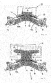
- both pressure medium actuators 13 and 14 can be extended so that the two axle carrier parts 10a and 10b pivot relative to one another, as is shown in a comparison of FIG Figures 1 and 2 shows.
- the pressure medium actuators 13 and 14 can be adjusted in opposite directions, in particular one of the pressure medium actuators can retract and the other pressure medium actuator are extended.
- the pressure medium actuators 13 and 14 can be moved into a corresponding position and fixed there.
- a pressure medium control device 15 which can control the application of pressure medium, in particular hydraulic fluid, to pressure medium actuators 13 and 14 in various ways.
- Said pressure medium control device 15 can have a valve arrangement 16 with one or more switching valves and / or control valves in order to control the pressurization of the pressure chambers of the pressure medium actuators 13 and 14 and to be able to connect it to various pressure medium circuit modules, in particular optionally with a pressure source, a return to the tank and in short circuit with a pressure chamber of other pressure medium actuators.
- the mentioned pressure medium actuators 13 and 14 can be single acting pressure medium cylinders, especially under the assumption that the weight of the harvesting machine always tries to push the wheel axles 8 and 9 of the bogey chassis 3 towards the machine frame 2 or upwards.
- double-acting hydraulic cylinders can be used, in order to be able to control the adjusting movements in both directions, in particular also to be able to control the rocking of the axle carrier 10 in the bogey mode according to the displacement principle.
- the pressure medium actuators 13 and 14 can be short-circuited in terms of flow, so that pressure fluid displaced from one pressure medium actuator forces an adjusting movement of the other pressure medium actuator.
- the pressure medium actuators 13 and 14 can be directly connected to one another in terms of flow, so that pressure fluid can actually flow from one pressure medium actuator into the other pressure medium actuator and flow back.
- it would also be possible to interpose a compensation cylinder in the short-circuit connection so that pressure fluid displaced from a pressure medium actuator forces an adjusting movement of the compensation cylinder, which in turn displaces pressure fluid from the compensation cylinder and thus forces an adjusting movement of the other pressure medium actuator. Any differences in the displacement volume or in the cross-sectional area of the pressure chambers of the two pressure medium actuators 13 and 14 can be compensated for by means of such an interposed compensating cylinder.
- the pressure medium actuators 13 and 14 can be shut off or separated from a pressure source and a return, so that a linked, short-circuited floating state of the two pressure medium actuators and thus free rocking of the axle carrier 10 is established, in which the two axle carrier parts 10a and 10b in a predetermined Relative position to each other are frozen.
- the displacement volumes are not exactly the same or are not compensated by a compensating cylinder, when the axle carrier 10 is rocked also result in relative movements of the axle carrier parts to one another in the sense of a slight kinking or stretching.
- such relative movements are kept small or avoided entirely by suitable selection of the displacement volumes or their compensation.
- the pressure medium control device 15 can terminate the short-circuit mode mentioned and connect the pressure chambers of the pressure medium actuators 13 and 14 to a pressure source in order to both extend the pressure medium actuators 13 and 14 in order to pivot the axle carrier parts relative to one another, as can be seen from a comparison of FIG Figures 1 and 2 shows.
- the pressure medium control device 15 can also connect the pressure medium actuators 13 and 14 in a desired manner to the pressure source or the return of the system in order to move to a certain actuator position, and then the pressure medium actuators 13 and 14 to shut off or to lock in order to maintain the approached position.
- the setting device for setting the positions of the axle carrier parts can also have more than two pressure medium actuators.
- at least two further pressure medium actuators 17 and 18 can be provided, which can be coupled to the first-mentioned pressure medium actuators 13 and 14, in particular connected in series, so that an adjustment of the further Pressure medium actuators 17 and 18 induce an adjusting movement of the axle carrier parts 10a and 10b via the first-mentioned pressure medium actuators 13 and 14.
- the mentioned further pressure medium actuators 17 and 18 can advantageously also be arranged on the same side of the axle support 10 as the other pressure medium actuators 13 and 14, in particular above the axle support 10.
- These further pressure medium actuators 17 and 18 can be articulated on the one hand to the pivot axis support 12 or a carrier part connected to the machine frame 2 and, on the other hand, have an articulation point which is coupled to the other pressure medium actuators 13 and 14.
- the further pressure medium actuators 17 and 18 and the first-mentioned pressure medium actuators 13 and 14 can each be articulated to a transmitter 19, which is movably mounted and converts the adjusting movement of the further pressure medium actuators 17 and 18 into a movement of the pivot points of the first-mentioned pressure medium actuators 13 and 14 on the pivoting axis support.
- Said transmitter 19 can in particular be designed as a pivotable transmission lever which is pivotably mounted on the pivot axis carrier 12. In principle, however, it would also be conceivable to provide a displaceably mounted transmitter, for example in such a way that the pressure medium actuators coupled to one another are articulated on a common pivot pin which is guided displaceably in a groove.
- the further pressure medium actuators 17 and 18 are coupled to the first-mentioned pressure medium actuators 13 and 14 in pairs.
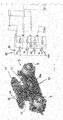
- a first pressure medium actuator 13 is coupled to a third pressure medium actuator 17, while the second pressure medium actuator 14 is coupled to the fourth pressure medium actuator 18, cf. Figures 3 and 4th .
- the pressure medium control device 15 can provide for the first and second pressure medium actuators 13 and 14 as well as for the third and fourth pressure medium actuators 17 and 18 in each case the operating modes described above, i.e. the rocker operating mode, the adjusting operating mode and the height adjustment mode and control the pressure medium actuators accordingly , whereby the pressure medium actuators 13 and 14 on the one hand and the pressure medium actuators 17 and 18 on the other hand can each be acted upon accordingly with pressure fluid individually or also in combination with one another.
- the operating modes described above i.e. the rocker operating mode, the adjusting operating mode and the height adjustment mode and control the pressure medium actuators accordingly , whereby the pressure medium actuators 13 and 14 on the one hand and the pressure medium actuators 17 and 18 on the other hand can each be acted upon accordingly with pressure fluid individually or also in combination with one another.
- the pressure medium control device 15 can also provide a special short-circuit connection between the pressure medium actuators, like this Fig. 3 shows.
- pairs of pressure medium actuators that are not coupled to one another via the aforementioned transmitter 19 can be short-circuited with one another.
- the first pressure medium actuator 13 can be short-circuited with the fourth pressure medium actuator 18, while the second pressure medium actuator 14 is short-circuited with the third pressure medium actuator 17, so that the displacement principle results in a rocking of the other axle support part when one axle support part is rocked down and vice versa.
- the pressure fluid displaced from the pressure medium actuator 13 or 14 when the one axle support part is rocked upwards forces an adjustment of the pressure medium actuator 17 or 18 short-circuited with it, which then leads via the respective transducer 19 to a corresponding adjusting movement of the other axle support part.
- Fig. 4 shows an example of a design of the pressure medium control device, which can advantageously have a plurality of switching valves in the form of multi-way switching valves.
- the multi-way switching valves mentioned can on the one hand Shut-off valves 21 for shutting off the respective pressure actuator from the pressure source and / or the return, and on the other hand switching valves 22 for switching the fluid connections between the pressure medium actuators and between a respective pressure medium actuator and the pressure source or the return.
- the multi-way switching valves 20 are advantageously designed, arranged and interconnected in such a way that the pressure medium actuators 13 and 14 or 17 and 18 can be optionally connected to a pressure source, a return or a short circuit in the above-mentioned manner, or separated from them, and also completely shut off in order to be able to hold an approached position.
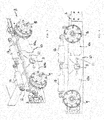
- FIG. 5 and 6 Another embodiment is shown in Figures 5 and 6 shown, which with regard to the formation of the wheel axles 8 and 9, the axle carrier 10 or its axle carrier parts 10a and 10b and the pivotability to the machine frame about the pivot axis 11 and the pivotability to each other about the pivot axis 111 essentially the previously described embodiment according to the Figs. 1 to 4 corresponds to.
- the main difference to the previously described embodiments is the arrangement of the pressure medium actuators 13 and 14.
- a first pressure medium actuator 13 can be articulated on the one hand to one axle support part 10a and articulated to the other axle support part 10b, the points of articulation being spaced apart from the pivot axis 111 in order to have a lever arm with respect to said pivot axis 111 and the two axle support parts 10a and 10b to be able to pivot relative to each other.
- the other, second pressure medium actuator 14 is articulated on the one hand to one of the axle carriers 10b and on the other hand to the pivoting axis carrier 12 or a carrier fixed to the frame.
- the articulation point on the axle support side of the second pressure medium actuator 14 can be combined with the articulation point of the first pressure medium actuator 13 on this axle support 10a.
- the two pressure medium actuators 13 and 14 can also be arranged on the same side of the axle support 10 in this embodiment, in particular above the axle support 10.
- the first pressure medium actuator 13 which is articulated on both axle support parts 10a and 10b, can be used for height adjustment. By extending and retracting the first pressure medium actuator 13, the axle support parts 10a and 10b can be pivoted relative to one another, as was previously done by comparing FIG Figures 1 and 2 was made clear. In order to freeze a specific relative pivot position of the two axle carrier parts 10a and 10b, the pressure medium actuator 13 can be shut off or locked.
- the pivot position of the entire axle carrier 10 with respect to the pivot axis 11 can be controlled by the other pressure medium actuator 14. If the axle carrier 10 is to rock up and down in the bogey mode, the pressure medium actuator 14 can be shut off from the pressure source and the return and / or switched to the floating position so that it can move freely to and fro apart from the flow resistance.
- the pressure medium control device 15 can switch the pressure medium actuator 14 accordingly in the rocker operating mode, in particular connect the opposing pressure chambers of the pressure medium actuator 14 with one another if the pressure chambers are of the same size in terms of displacement, or they can also be connected to one another via a compensating cylinder or with a return flow and fluid supply connect that free movement is possible.
- the two pressure medium actuators 13 and 14 can advantageously each be designed as double cylinders, with two pistons mounted on a common piston rod, each slidably received in a separate cylinder and separating two pressure chambers from one another so that each of the separate cylinders is designed to be double-acting is.
- Such double cylinders can not only be executed according to the Figures 5 and 6 be useful, but also with the previously explained execution according to the Figures 1 to 4 Find use.
- the pressure medium control device 15 can include several multi-way switching valves, by means of which the pressure chambers of the pressure medium cylinders 13 and 14 can be pressurized from a pressure source, switched to the tank without pressure and connected to one another or "short-circuited" in order to fill one another in opposite directions or to empty.
- the pressure medium actuator 14 controlling the axle support to the machine frame can be depressurized with all chambers in order to allow the axle support to rock back and forth, while the pressure medium actuator 13 controlling the relative movement can be pressure-connected in at least two of the four chambers, in order to hold a central position in which the two axle support parts can assume a central position relative to one another, for example the 180 ° position shown in the figures.
- the pressure control device 15 can switch the valves in such a way that the pressure medium actuator 13 controlling the relative movement is pressurized so that it moves together and accordingly swivels the two axle carrier parts upwards.
- the other pressure medium actuator 14, which controls the absolute angular position, can be switched to be depressurized with a cylinder part and be pressurized with the other cylinder in the elongating chamber to take a center position. If, however, a slope compensation is to take place downhill, the pressure medium actuator 13 can be pressurized in its two lengthening chambers in order to extend the two axle support parts downwards to one another, while the absolute pressure medium cylinder 14 can be depressurized.
- the pressure medium control device 15 can also include a curve control mode in which the rear bogey axle 9 is relieved or raised.
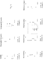
- the pressure medium actuator 14 controlling the absolute angular position to the machine frame can be pressurized in order to maintain a certain position, while in the double cylinder 13, which controls the axle carrier parts to each other, at least one pressure chamber that causes retraction (relief mode) or both Chambers that cause retraction (lifting mode) can be pressurized, as shown in the lower row of partial views of the Figure 7 show the second and fourth representation.
- the rear bogey axle 8 is to be loaded, for example in a bale transfer mode, and the rear wheel is lowered accordingly, pressure can be applied to the relative cylinder 13 in both chambers, which cause an extension of the double cylinder, so that the rear axle carrier part 10a is moved downwards becomes.
- the front axle carrier part 10b is held in a predetermined position by freezing the pressure medium actuator 14, for example by applying pressure to an extending pressure chamber and an extending pressure chamber of the double cylinder, as shown in the third illustration in the lower row of partial views in FIG Figure 7 shows.
- the pressure medium actuator 14 In order to move to a certain position in the actuating mode of the pressure medium control device 15, the pressure medium actuator 14 is in principle connected to the pressure source or the return line until the desired position is reached, whereupon the pressure medium actuator 14 can be locked, for example by locking a switching valve.
- the other pressure medium actuator 13 can also be moved into a corresponding, desired position by connecting it to the pressure source and / or the return and then locked in order to force and maintain a certain position of the two wheel axles.
Landscapes
- Engineering & Computer Science (AREA)
- Mechanical Engineering (AREA)
- Life Sciences & Earth Sciences (AREA)
- Environmental Sciences (AREA)
- Vehicle Body Suspensions (AREA)
Description
Die vorliegende Erfindung betrifft eine landwirtschaftliche Ernte- und/oder Bodenbearbeitungsmaschine mit einem Maschinenrahmen, der durch zumindest ein Bogey-Fahrwerk am Boden abgestützt ist, das zwei jeweils an einem Achsträger befestigte Radachsen aufweist, der zusammen mit den Radachsen nach Art einer Wippe um eine Schwenkachse schwenkbar gelagert ist, wobei der Achsträger zur Höhenverstellung des Bogey-Fahrwerks in zumindest zwei Achsträgerteile geteilt ist, die relativ zueinander schwenkbar sind.The present invention relates to an agricultural harvesting and / or soil cultivation machine with a machine frame which is supported on the ground by at least one bogey chassis, which has two wheel axles each attached to an axle carrier, which together with the wheel axles in the manner of a rocker around a pivot axis is pivotably mounted, wherein the axle support for height adjustment of the bogey chassis is divided into at least two axle support parts which are pivotable relative to one another.
Landwirtschaftliche Ernte- und/oder Bodenbearbeitungsmaschinen wie Ballenpressen oder Ladewagen mit einer Aufnahmevorrichtung zum Aufnehmen von Erntegut vom Boden werden gerne mit Bogey-Fahrwerken ausgestattet, da solche Bogey-Fahrwerke einerseits auch bei welligem Gelände eine günstige Bodenanpassung mit gleichmäßiger Lastverteilung auf beiden Achsen ermöglicht und zum anderen in einfacher Weise eine Höhenverstellung des Fahrwerks ermöglicht. Dabei kann die Höhenverstellung an den linken und rechten Fahrspuren auch unabhängig bzw. individuell erfolgen, sodass in einfacher Weise ein Hangausgleich erreicht werden kann, das heißt beim Parallelfahren am Hang quer zur Hangneigung kann das untere Bogey-Fahrwerk höher und/oder das hangaufwärts liegende Fahrwerk tiefer gestellt werden, sodass der Maschinenaufbau näherungsweise horizontal bzw. zumindest weniger stark geneigt und ein gewisser Neigungsausgleich erzielt wird. Bei den genannten Ballenpressen kann dies sinnvoll sein, um die Übergabe eines fertig gewickelten Ballens aus der Presskammer an die Wickelvorrichtung zu erleichtern. Beim Ladewagen kann dies sinnvoll sein, um beim Verteilen des Ernteguts im Speicherraum, beispielsweise durch Anschalten des Kratzbodens, eine gleichmäßige Futterverteilung zu erzielen.Agricultural harvesting and / or soil cultivation machines such as balers or loading wagons with a pick-up device for picking up crops from the ground are often equipped with bogey chassis, as such bogey chassis on the one hand enable favorable ground adaptation with even load distribution on both axles on the one hand, even on undulating terrain, and on the other allows others to adjust the height of the chassis in a simple manner. The height adjustment in the left and right lanes can also be done independently or individually, so that slope compensation can be achieved in a simple manner, i.e. when driving parallel on the slope transversely to the slope, the lower bogey chassis can be higher and / or the uphill chassis deeper be placed so that the machine structure is approximately horizontal or at least less inclined and a certain inclination compensation is achieved. In the case of the above-mentioned baling presses, this can be useful in order to facilitate the transfer of a completely wrapped bale from the baling chamber to the wrapping device. In the case of loading wagons, this can be useful in order to achieve an even distribution of forage when distributing the harvested material in the storage space, for example by switching on the scraper floor.
Solche Bogey-Fahrwerke können aber auch an anderen landwirtschaftlichen Maschinentypen sinnvoll sein, beispielsweise an Sämaschinen, Bodenbearbeitungsgeräten wie Pflüge, Grubber, Eggen oder Bodenbearbeitungskombinationen, sowie Heuwerbungsmaschinen wie Schwader und Zetter oder anderen landwirtschaftlichen Ernte- oder Bodenbearbeitungsmaschinen, insbesondere wenn diese als Anbaugeräte zum Anbau an einen Schlepper ausgebildet sind.Such bogey chassis can also be useful on other types of agricultural machinery, for example on seed drills, tillage equipment such as plows, cultivators, harrows or tillage combinations, as well as haymaking machines such as rakes and tedders or other agricultural harvesting or tillage machines, especially if they are used as attachments for cultivation a tractor are trained.
Die Schriften
In bestimmten Fahrsituationen bzw. Geländeformen kann ein solches Bogey-Fahrwerk jedoch auch hinderlich bzw. die genannte Höhenverstellung nicht ausreichend sein. Wird die Maschine beispielsweise über eine knickartige Hangkante ge fahren, kann die Maschine insgesamt ungewollt absacken, wenn eine der beiden Radachsen über die Hangkante hinaus auf die abschüssige Flanke gefahren ist, obwohl die andere Radachse an sich noch auf dem oberen Abschnitt der Hangkante platziert wäre. Hiervon abgesehen kann es beim Überfahren kleinerer Riefen bzw. kleinerer Querrinnen auch zu einem unruhigen Fahrverhalten mit vertikalen Stößen bzw. Vibrationen auf den Maschinenaufbau kommen. Während bei einer Zwillingsachse ohne Bogey-Funktion die noch nicht in eine Querrinne eingefahrene Achse den Aufbau weiter abstützen würde, sodass die andere Radachse sozusagen über die Querrille hinwegschweben kann, bzw. zumindest nicht voll in die Querrille eintaucht, kommt es bei einem Bogey-Fahrwerk aufgrund der gegenläufigen Wippbarkeit der Radachsen dazu, dass sich beim Eintauchen der einen Radachse in eine Querrille die andere Radachse einfach noch oben wegbewegt, sodass nacheinander beide Radachsen in die Querrille eintauchen. Ferner können Bogey-Fahrwerke auch bei höheren Fahrgeschwindigkeiten, beispielsweise im Straßentransportbetrieb, zu einer unerwünschten Beeinflussung des Fahrverhaltens beitragen.In certain driving situations or terrain forms, however, such a bogey chassis can also be a hindrance or the mentioned height adjustment can not be sufficient. If the machine is ge over a kink-like slope edge, for example drive, the machine can unintentionally sag as a whole if one of the two wheel axles has driven over the slope edge onto the sloping flank, although the other wheel axle itself would still be placed on the upper section of the slope edge. Apart from this, driving over smaller grooves or smaller transverse channels can also lead to restless driving behavior with vertical impacts or vibrations on the machine structure. While with a twin axle without a bogey function, the axle that has not yet retracted into a transverse groove would further support the body so that the other wheel axle can float over the transverse groove, or at least not fully immerse itself in the transverse groove, this is the case with a bogey chassis Due to the fact that the wheel axles can be tilted in opposite directions, when one wheel axle plunges into a transverse groove, the other wheel axle simply moves upwards so that both wheel axles dip into the transverse groove one after the other. Furthermore, bogey bogies can contribute to an undesirable influence on driving behavior even at higher driving speeds, for example in road transport operations.
Hiervon ausgehend liegt der vorliegenden Erfindung die Aufgabe zugrunde, eine verbesserte landwirtschaftliche Ernte- und/oder Bodenbearbeitungsmaschine zu schaffen, die Nachteile des Standes der Technik vermeidet und letzteren in vorteilhafter Weise weiterbildet. Insbesondere soll das den Maschinenrahmen am Boden abstützende Fahrwerk weiterentwickelt werden, um die Vorteile eines Bogey-Fahrwerks beizubehalten, dessen Nachteile jedoch zu eliminieren bzw. zumindest abzuschwächen, wobei trotz Höhenverstellbarkeit ein möglichst einfacher Aufbau des Fahrwerks mit wenig Teilen beibehalten werden soll.Proceeding from this, the present invention is based on the object of creating an improved agricultural harvesting and / or soil cultivating machine which avoids the disadvantages of the prior art and further develops the latter in an advantageous manner. In particular, the chassis supporting the machine frame on the ground is to be further developed in order to maintain the advantages of a bogey chassis, but to eliminate or at least weaken its disadvantages, whereby the chassis should be as simple as possible with few parts despite the height adjustability.
Erfindungsgemäß wird die genannte Aufgabe durch eine landwirtschaftliche Ernte- und/oder Bodenbearbeitungsmaschine gemäß Anspruch 1 gelöst. Bevorzugte Ausgestaltungen der Erfindung sind Gegenstand der abhängigen Ansprüche.According to the invention, the stated object is achieved by an agricultural harvesting and / or soil cultivating machine according to claim 1. Preferred embodiments of the invention are the subject matter of the dependent claims.
Es wird also vorgeschlagen, zusätzlich zur Höhenverstelleinrichtung, die die Winkelstellung der Achsträgerschenkel relativ zueinander verstellen kann, auch eine Einstellvorrichtung zum variablen Einstellen einer festen, vorgebbaren Winkelstellung des Achsträgers insgesamt bezüglich der Schwenkachse vorzusehen, um eine bestimmte Schwenkstellung des Achsträgers im Sinne einer absoluten Winkelstellung des Achsträgers relativ zum Maschinenrahmen vorgeben zu können. Erfindungsgemäß sind zumindest zwei Druckmittelaktoren zum Einstellen der Relativstellung der Achsträgerteile zueinander und zum Einstellen der Winkelstellung des Achsträgers bezüglich der Schwenkachse relativ zum Maschinenrahmen vorgesehen. Die zumindest zwei Druckmittelaktoren sind dabei derart angeordnet und ausgebildet, dass sie einerseits einen normalen Bogey-Fahrbetrieb mit gegenläufig auf und ab wippenden Radachsen ermöglichen, andererseits aber auch einen Fahrbetrieb mit sozusagen eingefrorener Schwenkstellung des Achsträgers bzw. das Feststellen zumindest eines Achsträgerteils bezüglich der Schwenkachse ermöglichen, und gleichermaßen eine Höhenverstellung des Bogey-Fahrwerks bewirken können.It is therefore proposed, in addition to the height adjustment device, which can adjust the angular position of the axle support legs relative to one another, also a Setting device for the variable setting of a fixed, predeterminable angular position of the axle carrier overall with respect to the pivot axis to be provided in order to be able to predetermine a specific pivot position of the axle carrier in the sense of an absolute angular position of the axle carrier relative to the machine frame. According to the invention, at least two pressure medium actuators are provided for setting the relative position of the axle support parts to one another and for setting the angular position of the axle support with respect to the pivot axis relative to the machine frame. The at least two pressure medium actuators are arranged and designed in such a way that, on the one hand, they enable normal bogey driving with wheel axles rocking up and down in opposite directions, but on the other hand they also enable driving with, so to speak, frozen pivot position of the axle carrier or the fixing of at least one axle carrier part with respect to the pivot axis , and can also adjust the height of the bogey chassis.
Hierdurch kann mit nur zwei Druckaktoren eine Vielseitigkeit der Fahrwerksfunktionen, verschiedene Hebe- und Senkszenarien und eine bessere Anpassung an verschiedene Fahrsituationen erzielt werden.As a result, a variety of chassis functions, different lifting and lowering scenarios and better adaptation to different driving situations can be achieved with just two pressure actuators.
In Weiterbildung der Erfindung können die genannten zumindest zwei Druckmittelaktoren jeweils einerseits an einem der Achsträgerteile und andererseits an einem Schwenkachsträger angelenkt sein, gegenüber dem das Bogey-Fahrwerk wippbar ist. Der genannte Schwenkachsträger kann beispielsweise ein mit dem Maschinenrahmen starr verbundener Fahrwerks-Aufhängungsträger, ggfs. aber auch ein verstellbares Rad- bzw. Achsaufhängungselement sein, gegenüber dem der Achsträger des Bogey-Fahrwerks mit beiden Achsträgerteilen verschwenkbar bzw. auf und nieder wippbar ist. Bei einer solchen Konfiguration bzw. Anlenkung der Druckmittelaktoren führt jeder der beiden Druckmittelaktoren eine Stellbewegung aus, wenn der Achsträger des Bogey-Fahrwerks im Bogey-Fahrbetrieb auf und nieder wippt.In a further development of the invention, said at least two pressure medium actuators can each be articulated on the one hand to one of the axle support parts and on the other hand to a pivoting axle support, with respect to which the bogey chassis can be luffed. Said swivel axle carrier can be, for example, a chassis suspension carrier rigidly connected to the machine frame, but possibly also an adjustable wheel or axle suspension element, with respect to which the axle carrier of the bogey chassis can be pivoted or rocked up and down with both axle carrier parts. With such a configuration or articulation of the pressure medium actuators, each of the two pressure medium actuators executes an adjusting movement when the axle carrier of the bogey chassis rocks up and down in the bogey driving mode.
Um einerseits die Wippbarkeit des gesamten Achsträgers mit gegenläufig schwenkenden, insbesondere zueinander eingefrorenen Achsträgerhälften bzw. - schenkeln zu erreichen, andererseits aber auch das Anfahren einer festen Winkelstellung des Achsträgers relativ zum Maschinenrahmen zu ermöglichen, kann in Weiterbildung der Erfindung eine Druckmittelsteuervorrichtung zum Ansteuern der genannten zumindest zwei Druckmittelaktoren vorgesehen sein, die für die Druckmittelaktoren verschiedene Betriebsmodi vorsieht, in denen die Druckmittelbeaufschlagung in verschiedener Weise gesteuert ist. Insbesondere kann die genannte Druckmittelsteuervorrichtung einen Wipp-Betriebsmodus aufweisen, in dem die Druckmittelaktoren miteinander kurzgeschlossen sind, sodass die Druckmittelaktoren nach dem Verdrängerprinzip Druckmittel hin- und herschieben bzw. hin- und herpumpen, wenn es beim Auf- und Niederwippen des Achsträgers zu entsprechenden Bewegungen der Druckmittelaktoren kommt. Im genannten Kurzschlussbetrieb können die Druckmittelzylinder von einer Druckmittelquelle und/oder von einem Rücklauf zum Tank der Druckmittelversorgung abgesperrt sein, sodass Druckmittel nur intern zwischen den Druckmittelaktoren zirkuliert bzw. hin und her verdrängt wird.In order, on the one hand, to ensure the rockability of the entire axle bracket with axle bracket halves or axles that pivot in opposite directions, in particular that are To achieve legs, but on the other hand also to enable the axle carrier to move to a fixed angular position relative to the machine frame, a pressure medium control device can be provided in a further development of the invention to control the at least two pressure medium actuators mentioned, which provides different operating modes for the pressure medium actuators in which the pressure medium application in is controlled in different ways. In particular, the said pressure medium control device can have a rocker operating mode in which the pressure medium actuators are short-circuited with one another so that the pressure medium actuators push pressure medium back and forth or pump back and forth according to the displacement principle if corresponding movements of the Pressure medium actuators comes. In the short-circuit operation mentioned, the pressure medium cylinders can be shut off from a pressure medium source and / or from a return to the tank of the pressure medium supply, so that pressure medium is only circulated or displaced back and forth internally between the pressure medium actuators.
Insbesondere können die genannten Druckmittelaktoren derart kurzgeschlossen sein, dass beim Aufwippen oder Niederwippen eines Achsträgerteils das aus dem damit verbundenen Druckmittelaktor verdrängte Druckfluid eine Stellbewegung des anderen Druckmittelaktors erzwingt, die zu einem gegenläufigen Niederwippen oder Aufwippen des mit dem genannten anderen Druckmittelaktor verbundenen anderen Achsträgerteils führt. Die Druckmittelaktoren sind also derart miteinander kurzgeschlossen, dass sie gegenseitig Stellbewegungen erzwingen, die zu einem Verschwenken bzw. Verwippen der Achsträgerteile in der gleichen Drehrichtung führen.In particular, the mentioned pressure medium actuators can be short-circuited in such a way that when one axle carrier part is rocked up or down, the pressure fluid displaced from the associated pressure medium actuator forces an adjusting movement of the other pressure medium actuator, which leads to a counter-rocking down or up of the other axle carrier part connected to the mentioned other pressure medium actuator. The pressure medium actuators are thus short-circuited to one another in such a way that they mutually force adjusting movements which lead to pivoting or rocking of the axle carrier parts in the same direction of rotation.
Je nach Anordnung und Anlenkung der Druckmittelaktoren können dies gegenläufige oder gleichlaufende Stellbewegungen der Druckaktoren sein. Sind beispielsweise als Druckmittelaktoren zwei Druckmittelzylinder vorgesehen, die auf derselben Seite des Achsträgers angeordnet bzw. auf derselben Seite der Schwenkachse an dem Schwenkachsträger angelenkt sind, sodass sich der eine Druckmittelzylinder längen und der andere Druckmittelzylinder verkürzen muss, um den Achsträger insgesamt bogey-artig zu verwippen bzw. die eine Radachse nach oben und die andere Radachse nach unten zu schwenken, können die beiden Druckmittelzylinder kreuzweise miteinander kurzgeschlossen werden, sodass Druckfluid, das beim Verkürzen des einen Zylinders aus diesem verdrängt wird, ein Längen des anderen Zylinders erzwingt.Depending on the arrangement and linkage of the pressure medium actuators, these can be counter-rotating or synchronous adjusting movements of the pressure actuators. For example, two pressure medium cylinders are provided as pressure medium actuators, which are arranged on the same side of the axle support or are articulated on the same side of the pivot axis on the swivel axle support, so that one pressure medium cylinder has to lengthen and the other pressure medium cylinder has to shorten by the axle support overall bogey-like rocking or swiveling one wheel axle upwards and the other wheel axle downwards, the two hydraulic cylinders can be short-circuited crosswise so that pressure fluid that is displaced from one cylinder when it is shortened lengthen the other cylinder enforces.
Sind indes die genannten Druckmittelzylinder auf unterschiedlichen Seiten des Achsträgers angeordnet bzw. auf gegenüberliegenden Seiten der Schwenkachse angelenkt, beispielsweise in einer z-artigen Konfiguration oder in einer Konfiguration mit einem Zylinder oberhalb und einem Zylinder unterhalb des Achsträgers, sodass sich beide Druckmittelzylinder längen, um ein Wippen des gesamten Achsträgers in die eine Richtung zu ermöglichen und beide Druckmittelzylinder verkürzen, um ein Verwippen des Achsträgers in die andere Richtung zu ermöglichen, können die Druckmittelaktoren auch derart miteinander kurzgeschlossen sein, dass sich gleichläufige Stellbewegungen ergeben. In diesem Fall erzwingt das beim Verkürzen des einen Zylinders verdrängte Druckfluid ebenfalls eine Verkürzung des anderen Druckmittelzylinders, während das beim Längen des einen Druckmittelzylinders verdrängte Druckfluid ebenfalls ein Längen des anderen Druckmittelzylinders erzwingt.If, however, the mentioned pressure medium cylinders are arranged on different sides of the axle support or articulated on opposite sides of the pivot axis, for example in a z-like configuration or in a configuration with a cylinder above and a cylinder below the axle support, so that both pressure medium cylinders lengthen by a To enable rocking of the entire axle carrier in one direction and to shorten both pressure cylinders in order to allow the axle carrier to rock in the other direction, the pressure medium actuators can also be short-circuited to one another in such a way that synchronous adjusting movements result. In this case, the pressure fluid displaced when one cylinder is shortened also forces a shortening of the other pressure medium cylinder, while the pressure fluid displaced when one pressure medium cylinder is lengthened also forces the other pressure medium cylinder to be lengthened.
Zusätzlich zu dem genannten Wipp-Betriebsmodus besitzt die zuvor genannte Druckmittelsteuervorrichtung vorteilhafterweise auch einen Stellbetriebsmodus, in dem zumindest einer der genannten Druckmittelaktoren mit einer Druckquelle und/oder einem Rücklauf verbunden ist, um durch Druckmittelbeaufschlagung und/oder Druckmittelablassen eine vorbestimmte Schwenkstellung anzufahren, und dann in der vorbestimmten Stellung feststellbar ist, beispielsweise indem zumindest eine Druckkammer des Druckmittelaktors mittels eines Sperrventils abgesperrt wird. In dem besagten Stellbetriebsmodus sieht die Druckmittelsteuervorrichtung also ein aktives Einstellen und Feststellen einer vorbestimmten Stellung des Druckmittelaktors vor, sodass der damit verbundene Achsträgerteil in einer absoluten Winkelstellung festgestellt werden kann, da der genannte Stellaktor wie oben erläutert einen Anlenkpunkt am Schwenkachsträger oder einem damit verbundenen Anlenkteil besitzt.In addition to the aforementioned rocker operating mode, the aforementioned pressure medium control device advantageously also has an actuating mode in which at least one of the aforementioned pressure medium actuators is connected to a pressure source and / or a return in order to move to a predetermined pivot position by applying pressure medium and / or releasing pressure medium, and then in the predetermined position can be determined, for example, in that at least one pressure chamber of the pressure medium actuator is shut off by means of a shut-off valve. In the said actuating operating mode, the pressure medium control device provides an active setting and determination of a predetermined position of the pressure medium actuator so that the axle carrier part connected to it can be determined in an absolute angular position, since the said actuating actuator is as above explains a point of articulation on the pivot axis support or an articulation part connected therewith.
Vorteilhafterweise kann die Druckmittelsteuervorrichtung in dem besagten Stellbetriebsmodus beide Druckmittelaktoren durch Verbinden mit der Druckquelle und/oder dem Rücklauf in eine vorbestimmte absolute Winkelstellung relativ zum Maschinenrahmen fahren und feststellen, sodass die Position beider Radachsen des Bogey-Fahrwerks einstellbar und feststellbar ist.Advantageously, the pressure medium control device can move and determine both pressure medium actuators by connecting to the pressure source and / or the return in a predetermined absolute angular position relative to the machine frame in the said actuating operating mode, so that the position of both wheel axles of the bogey chassis can be adjusted and determined.
Vorteilhafterweise kann die genannte Druckmittelsteuervorrichtung weiterhin einen Höhenverstellmodus aufweisen, in dem die beiden Druckmittelaktoren jeweils mit der genannten Druckquelle, ggfs. auch mit zwei separaten Druckquellen - oder einem Rücklauf - ggfs. auch mit zwei separaten Rückläufen - verbunden sind, um die relative Winkelstellung der beiden Achsträgerteile relativ zueinander verstellen und damit die Höhe des Bogey-Fahrwerks einstellen zu können.Advantageously, said pressure medium control device can furthermore have a height adjustment mode in which the two pressure medium actuators are each connected to the mentioned pressure source, possibly also with two separate pressure sources - or a return - possibly also with two separate returns - to adjust the relative angular position of the two Adjust the axle support parts relative to each other and thus adjust the height of the bogey chassis.
Die genannte Druckmittelsteuervorrichtung kann vorteilhafterweise eine Ventileinrichtung umfassen, die verschiedene Schaltstellungen hat, in denen die Druckmittelaktoren in der zuvor beschriebenen Weise miteinander kurzgeschlossen und wahlweise mit einer Druckquelle oder einem Rücklauf verbunden werden können. Die genannte Ventil-einrichtung kann mehrere Sperrventile und/oder Mehrwegeventile aufweisen.Said pressure medium control device can advantageously comprise a valve device which has various switching positions in which the pressure medium actuators can be short-circuited with one another in the manner described above and optionally connected to a pressure source or a return. Said valve device can have a plurality of shut-off valves and / or multi-way valves.
Die genannten Druckmittelaktoren und deren Druckmittelsteuervorrichtung sind dabei vorteilhafterweise derart ausgebildet, dass sich die Druckmittelaktoren im genannten Kurzschluss- bzw. Wipp-Betriebsmodus zumindest näherungsweise miteinander synchronisiert bewegen, sodass sich die durch die Druckmittelaktoren gesteuerten Achsträgerschenkel zumindest näherungsweise synchron miteinander, das heißt um näherungsweise gleiche Schwenkwinkel verschwenken. Eine vollständige Synchronisation der Achsträgerteile ist dabei nicht notwendig, kann gleichwohl aber vorgesehen sein, sodass die Achsträgerschenkel im Wipp-Betriebsmodus tatsächlich starr zueinander eingefroren sind und sich lediglich um die Schwenkachse auf und nieder wippen können, ohne Relativbewegungen zueinander auszuführen.The mentioned pressure medium actuators and their pressure medium control device are advantageously designed in such a way that the pressure medium actuators move at least approximately synchronized with one another in the mentioned short-circuit or rocker operating mode, so that the axle carrier legs controlled by the pressure medium actuators move at least approximately synchronously with one another, i.e. by approximately the same pivot angle pivot. Complete synchronization of the axle support parts is not necessary, but it can be provided so that the axle support legs are actually frozen rigidly to one another in the rocker operating mode and only turn around the pivot axis can rock up and down without performing relative movements to each other.
Um eine solchermaßen zumindest näherungsweise synchronisierte Verstellung der Druckmittelaktoren zu erzielen, können die Druckmittelaktoren einander entsprechende Verdrängungsvolumina haben, sodass die durch das verdrängte Druckfluid eines Druckmittelaktors erzwungene Stellbewegung des anderen Druckmittelaktors betragsmäßig zumindest näherungsweise dieselbe ist. Sind die Verdrängungsvolumina der beiden Druckmittelaktoren näherungsweise gleich groß, können die Druckmittelaktoren direkt miteinander kurzgeschlossen werden.In order to achieve an at least approximately synchronized adjustment of the pressure medium actuators in this way, the pressure medium actuators can have mutually corresponding displacement volumes so that the adjusting movement of the other pressure medium actuator forced by the displaced pressure fluid of one pressure medium actuator is at least approximately the same in terms of magnitude. If the displacement volumes of the two pressure medium actuators are approximately the same, the pressure medium actuators can be short-circuited directly to one another.
Alternativ oder zusätzlich kann im Kurzschlusskreis der beiden Druckmittelaktoren jedoch auch ein Ausgleichszylinder vorgesehen sein, der ggfs. unterschiedlich Verdrängungsvolumina ausgleicht bzw. zumindest ein Stück weit aneinander angleicht. Ein solcher Ausgleichszylinder kann unterschiedlich große Druckkammern aufweisen, wobei eine im Querschnitt größere Druckkammer mit dem Druckmittelaktor größeren Verdrängungsvolumens und die Druckkammer kleinerer Querschnittsfläche mit dem Druckmittelaktor kleineren Verdrängungsvolumens verbunden sein kann.As an alternative or in addition, however, a compensating cylinder can also be provided in the short-circuit circuit of the two pressure medium actuators, which compensates for different displacement volumes or at least approximates them to a certain extent. Such a compensating cylinder can have pressure chambers of different sizes, wherein a pressure chamber with a larger cross section can be connected to the pressure medium actuator with a larger displacement volume and the pressure chamber with a smaller cross-sectional area can be connected to the pressure medium actuator with a smaller displacement volume.
Je nach Anordnung der Druckmittelaktoren können die genannten Druckmittelaktoren im Kurzschlussmodus kreuzweise miteinander kurzgeschlossen sein, um gegenläufige Bewegungen auszuführen, oder parallel zueinander kurzgeschlossen sein, um gleichsinnige Bewegungen auszuführen. Wie zuvor erwähnt, können beispielsweise Druckmittelzylinder jeweils oberhalb des Achsträgers angeordnet und auf derselben Seite der Schwenkachse einen Anlenkpunkt besitzen, sodass sie sich gegenläufig verstellen, das heißt der eine Druckmittelzylinder sich längen und der andere Druckmittelzylinder sich verkürzen muss, um einen wippenden Bogey-Betrieb zu ermöglichen. In diesem Fall kann der genannte kreuzweise Kurzschluss vorgesehen sein. Ist andererseits - wie oben schon angesprochen - eine Anordnung der Druckmittelzylinder - beispielsweise ein Druckmittelzylinder oberhalb des Achsträgers und ein Druckmittelzylinder unterhalb des Achsträgers - vorgesehen, bei der sich beide Druckmittelzylinder längen, wenn der Achsträger insgesamt in die eine Richtung wippt, und sich beide Druckmittelzylinder verkürzen, wenn der Achsträger in die andere Richtung wippt, kann die genannte parallele Kurzschlussschaltung vorgesehen werden, um ein gleichlaufendes Verstellen der Zylinder zu erreichen.Depending on the arrangement of the pressure medium actuators, said pressure medium actuators can be short-circuited with one another in the short-circuit mode in order to carry out movements in opposite directions, or they can be short-circuited parallel to one another in order to carry out movements in the same direction. As mentioned above, for example, pressure cylinders can be arranged above the axle carrier and have a pivot point on the same side of the pivot axis so that they move in opposite directions, i.e. one pressure cylinder has to lengthen and the other pressure cylinder has to shorten in order to achieve a rocking bogey operation enable. In this case, said cross-over short circuit can be provided. On the other hand - as already mentioned above - an arrangement of the pressure medium cylinders - for example a pressure medium cylinder above the axle support and a pressure medium cylinder below the axle support - is provided, In which both pressure cylinders elongate when the axle carrier rocks in one direction and both pressure cylinders shorten when the axle carrier rocks in the other direction, said parallel short-circuit circuit can be provided in order to achieve synchronous adjustment of the cylinders.
Um verschiedene Achspositionen auch ohne Wegmess-Sensorik anfahren und feststellen und/oder einen größeren Höhenverstellbereich erzielen zu können, können in Weiterbildung der Erfindung auch mehr als zwei Druckmittelaktoren vorgesehen sein. Insbesondere können zwei weitere Druckmittelaktoren vorgesehen sein, die mit den beiden erstgenannten Druckmittelaktoren paarweise gekoppelt, insbesondere hintereinandergeschaltet sein können, sodass sich die Stellbewegung der weiteren Druckmittelaktoren über die erstgenannten Druckmittelaktoren auf die jeweiligen Achsträger überträgt. Ist beispielsweise ein erster Druckmittelaktor mit einem dritten Druckmittelaktor gekoppelt und ein zweiter Druckmittelaktor mit einem vierten Druckmittelaktor gekoppelt, kann die Stellbewegung des dritten Druckmittelaktors durch den ersten Druckmittelaktor auf den damit verbundenen Achsträger übertragen werden, während eine Stellbewegung des vierten Druckmittelaktors über den zweiten Druckmittelaktor auf den damit verbundenen Achsträger übertragen wird.In order to be able to approach and determine different axis positions without a displacement measuring sensor system and / or to achieve a larger height adjustment range, more than two pressure medium actuators can also be provided in a further development of the invention. In particular, two further pressure medium actuators can be provided, which can be coupled to the two first-mentioned pressure medium actuators in pairs, in particular connected in series, so that the actuating movement of the further pressure medium actuators is transmitted to the respective axle carrier via the first pressure medium actuators. If, for example, a first pressure medium actuator is coupled to a third pressure medium actuator and a second pressure medium actuator is coupled to a fourth pressure medium actuator, the actuating movement of the third pressure medium actuator can be transmitted to the axle carrier connected to it by the first pressure medium actuator, while an actuating movement of the fourth pressure medium actuator is transmitted to the associated axle carrier is transmitted.
Insbesondere können die beiden weiteren Druckmittelaktoren - im zuvor beschriebenen Beispiel die dritten und vierten Druckmittelaktoren - dazu vorgesehen sein, die Anlenkpunkte der beiden erstgenannten Druckmittelaktoren - also des ersten und zweiten Druckmittelaktors - an dem Schwenkachsträger zu verstellen. Werden die dritten und vierten Druckmittelaktoren ein- oder ausgefahren, verschieben sich die Anlenkpunkte der ersten und zweiten Druckmittelaktoren an dem genannten Schwen kachsträger.In particular, the two further pressure medium actuators - the third and fourth pressure medium actuators in the example described above - can be provided to adjust the articulation points of the first two pressure medium actuators - that is, the first and second pressure medium actuators - on the pivot axle support. If the third and fourth pressure medium actuators are retracted or extended, the articulation points of the first and second pressure medium actuators move on the said pivoting kachträger.
Beispielsweise können die genannten vier Druckmittelaktoren paarweise über Übertrager beispielsweise in Form von Schwenkhebeln miteinander gekoppelt sein, wobei die genannten Schwenkhebel jeweils an dem Schwenkachsträger schwenkbar gelagert sein können. Durch eine solche Koppelung mittels Schwenkhebeln kann einerseits eine sehr kompakte Bauweise erzielt werden, bei der sich die dritten und vierten Druckmittelaktoren unabhängig von der gewünschten Verstellrichtung für die Anlenkpunkte der ersten und zweiten Druckmittelaktoren anordnen lassen. Zum anderen kann über die genannten Schwenkhebel auch ein Übersetzungs- oder Untersetzungseffekt erzielt werden, der bei begrenztem Stellweg der Druckmittelaktoren und/oder begrenzter Baugröße der Druckmittelaktoren die gewünschte Stellbewegung ermöglicht.For example, the four pressure medium actuators mentioned can be coupled to one another in pairs via transmitters, for example in the form of pivot levers, the pivot levers mentioned each being pivotable on the pivot axis support can be stored. Through such a coupling by means of pivot levers, on the one hand, a very compact design can be achieved in which the third and fourth pressure medium actuators can be arranged independently of the desired adjustment direction for the articulation points of the first and second pressure medium actuators. On the other hand, a step-up or step-down effect can also be achieved via the pivot levers mentioned, which enables the desired adjustment movement with a limited adjustment path of the pressure medium actuators and / or a limited size of the pressure medium actuators.
Sind in der genannten Weise zumindest vier Druckmittelaktoren vorgesehen, die paarweise miteinander gekoppelt sind, kann die Druckmittelsteuervorrichtung in ihrem Wipp-Betriebsmodus an sich die ersten und zweiten Druckmittelaktoren miteinander kurzschließen wie zuvor beschrieben, wobei die dritten und vierten Druckmittelaktoren hierbei abgesperrt bzw. festgestellt werden können, sodass sich der Bogey- bzw. Wipp-Betrieb nur durch Bewegen der ersten und zweiten Druckmittelzylinder bewerkstelligen lässt.If at least four pressure medium actuators are provided in the manner mentioned, which are coupled to one another in pairs, the pressure medium control device in its rocker operating mode can in itself short-circuit the first and second pressure medium actuators to one another as described above, whereby the third and fourth pressure medium actuators can be blocked or determined so that the bogey or rocker operation can only be achieved by moving the first and second pressure cylinder.
Alternativ hierzu kann die Druckmittelsteuervorrichtung im Wipp-Betriebsmodus vorteilhafterweise aber auch einen Kurzschluss zwischen den Druckmittelzylindern vorsehen, der auch die zusätzlichen dritten und vierten Druckmittelaktoren miteinbezieht. Insbesondere können die beiden erstgenannten Druckmittelaktoren, die an den Achsträgerteilen angelenkt sind, jeweils mit dem zusätzlichen Druckmittelaktor kurzschließbar sein, mit dem sie jeweils nicht hintereinandergeschaltet und nicht durch den genannten Übertrager gekoppelt sind. Ist beispielsweise in der vorgenannten Weise der erste Druckmittelzylinder - ggfs. über den beschriebenen Schwenkhebel - mit dem dritten Druckmittelaktor gekoppelt und hintereinander geschaltet, kann der genannte erste Druckmittelzylinder mit dem vierten Druckmittelzylinder kurzschließbar sein, der mit dem zweiten Druckmittelaktor - ggfs. über einen weiteren Schwenkhebel - gekoppelt ist. Der genannte zweite Druckmittelzylinder ist dann mit dem vorgenannten dritten Druckmittelaktor kurzschließbar.As an alternative to this, the pressure medium control device in the rocker operating mode can, however, advantageously also provide a short circuit between the pressure medium cylinders, which also includes the additional third and fourth pressure medium actuators. In particular, the two first-mentioned pressure medium actuators, which are articulated to the axle support parts, can each be short-circuited with the additional pressure medium actuator, with which they are not connected in series and are not coupled through the said transducer. If, for example, the first pressure medium cylinder - possibly via the pivot lever described - is coupled to the third pressure medium actuator and connected in series in the aforementioned manner, said first pressure medium cylinder can be short-circuited with the fourth pressure medium cylinder, which can be short-circuited with the second pressure medium actuator - if necessary via a further pivot lever - is coupled. The named second pressure medium cylinder can then be short-circuited with the aforementioned third pressure medium actuator.
Dementsprechend erzwingen Bewegungen der ersten und zweiten Druckmittelaktoren entsprechende Bewegungen der dritten und vierten Druckmittelaktoren, sodass sich alle vier genannten Druckmittelaktoren verstellen, wenn der Achsträger insgesamt, das heißt mit beiden Achsträgerteilen, um die Schwenkachse im Bogey-Fahrbetrieb auf und nieder wippt.Accordingly, movements of the first and second pressure medium actuators force corresponding movements of the third and fourth pressure medium actuators, so that all four mentioned pressure medium actuators are adjusted when the axle carrier as a whole, i.e. with both axle carrier parts, rocks up and down about the pivot axis in bogey mode.
Die erstgenannten zumindest zwei Druckmittelaktoren müssen jedoch nicht in der zuvor beschriebenen Weise jeweils einerseits an einer Achsträgerhälfte und andererseits an dem Schwenkachsträger bzw. einem anderen maschinenrahmenfesten Teil angelenkt sein. In alternativer Weiterbildung der Erfindung nach einem weiteren vorteilhaften Ausführungsbeispiel können die beiden Druckmittelaktoren auch getrennte bzw. unterschiedliche Funktionsaufgaben haben und unterschiedlich angelenkt sein. Insbesondere kann der eine Druckmittelaktor für die Höheneinstellung des Bogey-Fahrwerks vorgesehen sein, insbesondere zum Verschwenken der beiden Achsträgerteile relativ zueinander angeordnet und ausgebildet sein, während der andere der zumindest zwei Druckmittelaktoren dazu vorgesehen sein kann, die absolute Winkelstellung des Achsträgers relativ zum Maschinenrahmen einzustellen und/oder festzustellen.However, the first-mentioned at least two pressure medium actuators do not have to be articulated in the manner described above, on the one hand, on an axle support half and, on the other hand, on the pivoting axle support or another part fixed to the machine frame. In an alternative development of the invention according to a further advantageous embodiment, the two pressure medium actuators can also have separate or different functional tasks and be articulated differently. In particular, the one pressure medium actuator can be provided for the height adjustment of the bogey chassis, in particular arranged and designed to pivot the two axle support parts relative to one another, while the other of the at least two pressure medium actuators can be provided to set the absolute angular position of the axle support relative to the machine frame and / or determine.
Insbesondere kann einer der beiden Druckmittelaktoren Anlenkpunkte an verschiedenen Achsträgerteilen aufweisen, sodass ein Verstellen des Druckmittelaktors ein Verschwenken der beiden Achsträgerteile relativ zueinander bewirkt. Der andere der beiden Druckmittelaktoren kann einerseits an einem der beiden Achsträgerteile angelenkt sein und andererseits einen maschinenrahmenfesten Anlenkpunkt besitzen bzw. an dem zuvor schon genannten Schwenkachsträger oder einem damit verbundenen Element, gegenüber dem sich der Achsträger beim Bogey-Wippen verdrehen muss, angelenkt sein.In particular, one of the two pressure medium actuators can have articulation points on different axle support parts, so that an adjustment of the pressure medium actuator causes the two axle support parts to pivot relative to one another. The other of the two pressure medium actuators can on the one hand be articulated on one of the two axle support parts and on the other hand have an articulation point fixed to the machine frame or be articulated on the previously mentioned swivel axle support or an element connected to it, with respect to which the axle support has to rotate when bogey rocking.
Da jeder Druckmittelaktor seine eigene Aufgabe hat, können die Druckmittelaktoren individuell an ihre jeweilige Aufgabe angepasst sein und insbesondere auch voneinander verschieden ausgebildet sein. Beispielsweise kann der die beiden Achsteile zueinander verstellende Druckmittelaktor einen anderen Stellweg und/oder einen anderen Kolbendurchmesser aufweisen als der Druckmittelaktor, der die Winkelstellung der Achsteile relativ zum Maschinenrahmen einstellt. Alternativ oder zusätzlich kann auch die Druckmittelsteuervorrichtung für die beiden Druckmittelaktoren unterschiedlich ausgebildet sein, insbesondere verschiedene Ventilanordnungen umfassen, mittels derer der jeweilige Druckmittelaktor angesteuert werden kann.Since each pressure medium actuator has its own task, the pressure medium actuators can be individually adapted to their respective task and, in particular, can also be designed differently from one another. For example, the pressure medium actuator which adjusts the two axle parts to one another can have a different travel and / or a different travel path have a different piston diameter than the pressure medium actuator, which sets the angular position of the axle parts relative to the machine frame. Alternatively or additionally, the pressure medium control device for the two pressure medium actuators can also be designed differently, in particular comprise different valve arrangements by means of which the respective pressure medium actuator can be controlled.
Bei einer derartigen Funktionsteilung der Druckmittelaktoren kann die zuvor genannte Druckmittelsteuereinrichtung in ihrem Wipp-Betriebsmodus den Druckmittelaktor, der Anlenkpunkte an beiden Achsträgerteilen hat und für die Höhenverstellung zuständig ist, sperren, beispielsweise durch Verriegeln längenunveränderbar machen und somit die Relativstellung der beiden Achsträgerteile zueinander einfrieren, und den anderen Druckmittelaktor, der einen maschinenrahmenfesten Anlenkpunkt hat, in Schwimmstellung schalten.With such a division of functions of the pressure medium actuators, the aforementioned pressure medium control device can, in its rocker operating mode, block the pressure medium actuator, which has articulation points on both axle support parts and is responsible for the height adjustment, for example by locking it to make it unchangeable in length and thus freeze the relative position of the two axle support parts to one another, and Switch the other pressure medium actuator, which has an articulation point fixed to the machine frame, into the floating position.
Andererseits kann die genannte Druckmittelsteuereinrichtung in ihrem Stellbetriebsmodus den genannten Druckmittelaktor mit einem maschinenrahmenfesten Anlenkpunkt durch Druckbeaufschlagung oder Verbinden mit dem Rücklauf in eine vorbestimmte Betriebsstellung fahren und feststellen, wobei der andere Druckmittelaktor mit Anlenkpunkten an beiden Achsteilen verriegelt bleiben kann oder ebenfalls in eine andere Stellung verfahren und dann verriegelt werden kann. Gegebenenfalls wäre es auch denkbar, den genannten Druckmittelaktor, der Anlenkpunkte an beiden Achsträgerteilen hat, in Schwimmstellung zu schalten, wobei in diesem Fall dann das gesamte Gewicht von dem anderen Achsträgerteil abzufangen wäre, welches durch den Druckmittelaktor mit maschinenrahmenfestem Anlenkpunkt verriegelt ist.On the other hand, said pressure medium control device in its setting mode of operation can move said pressure medium actuator with an articulation point fixed to the machine frame by applying pressure or connecting it to the return line into a predetermined operating position and determine it, with the other pressure medium actuator remaining locked with articulation points on both axle parts or also moving into another position and can then be locked. If necessary, it would also be conceivable to switch the said pressure medium actuator, which has articulation points on both axle support parts, into the floating position, in which case the entire weight of the other axle support part would then be intercepted, which is locked by the pressure medium actuator with the articulation point fixed to the machine frame.
Eine solche ungleiche Lastverteilung auf die beiden Bogey-Achsen kann insbesondere auch dazu genutzt werden, bei engeren Kurvenfahrten ein Radieren der Räder zu vermeiden. Insbesondere kann die Drucksteuervorrichtung einen Kurvenbetriebsmodus umfassen, in dem eine der beiden Radachsen entlastet und/oder angehoben wird, während die andere Radachse belastet wird, um das Maschinengewicht gegebenenfalls zusammen mit der Abstützkraft der Deichsel zu tragen. Insbesondere kann bei Kurvenfahrten die hintere der beiden Bogey-Radachsen entlastet und/oder angehoben werden, was beispielsweise dadurch erfolgen kann, dass die Drucksteuervorrichtung den Druckmittelaktor, der eines der Achsträgerteile, insbesondere das vordere Achsträgerteil am Maschinenrahmen abstützt, verriegelt und/oder mit ausreichendem Druck beaufschlagt, während der Druckmittelaktor, der die beiden Achsträgerteile relativ zueinander verstellen kann, in Schwimmstellung gebracht wird oder aktiv mit Druck beaufschlagt wird, um die Radachse sogar leicht anzuheben.Such an unequal load distribution on the two bogey axles can in particular also be used to avoid the wheels from being erased when cornering more closely. In particular, the pressure control device can include a cornering operating mode in which one of the two wheel axles is relieved and / or raised while the other wheel axle is loaded by the weight of the machine if necessary to be carried together with the support force of the drawbar. In particular, when cornering, the rear of the two bogey wheel axles can be relieved and / or raised, which can be done, for example, in that the pressure control device locks and / or applies sufficient pressure to the pressure medium actuator that supports one of the axle support parts, in particular the front axle support part, on the machine frame applied, while the pressure medium actuator, which can adjust the two axle carrier parts relative to one another, is brought into the floating position or is actively pressurized in order to even slightly raise the wheel axle.
Die Druckmittelsteuervorrichtung kann hierzu in Abhängigkeit eines Kurvenfahrsignals arbeiten, wobei ein solches Kurvenfahrsignal in unterschiedlicher Weise gewonnen bzw. bereitgestellt werden kann. Beispielsweise kann dies ein Lenkeinschlagsignal des Schleppers sein, das den Lenkeinschlag des Schleppers angibt. Alternativ oder zusätzlich kann mit einer Sensorik auch das Einlenken der Deichsel des Anbaugeräts gegenüber dem Schlepper bzw. gegenüber einem Anbaugeschirr gemessen werden und als Kurvenfahrsignal verwendet werden, in Abhängigkeit dessen eine der Bogey-Achsen entlastet und/oder angehoben werden kann.For this purpose, the pressure medium control device can work as a function of a cornering signal, wherein such a cornering signal can be obtained or provided in different ways. For example, this can be a steering angle signal from the tractor that indicates the steering angle of the tractor. Alternatively or additionally, the deflection of the drawbar of the attachment towards the tractor or attachment can be measured and used as a cornering signal, depending on which one of the bogey axles can be relieved and / or raised.
Alternativ oder zusätzlich kann eine solche ungleiche Radachsbelastung auch in anderen Betriebssituationen sinnvoll sein und von der Drucksteuervorrichtung vorgesehen werden. Ist das Anbaugerät beispielsweise eine Ballenpresse, kann es sinnvoll sein, für die Ballenübergabe von der Ballenformkammer auf den in Fahrtrichtung nachlaufenden Wickler die in Fahrtrichtung hintere Bogey-Achse stärker zu belasten und/oder die vordere Bogey-Fahrachse zu entlasten, sodass das Gewicht des Ballens bei der Übergabe stärker durch die hintere und/oder näher am Ballen liegende Radachse abgestützt wird. Hierdurch können Stöße, die beim Übergeben des Ballens auf den Wickler entstehen, besser abgefangen und vom Schlepper ferngehalten werden.As an alternative or in addition, such an unequal wheel axle load can also be useful in other operating situations and can be provided by the pressure control device. If the attachment is, for example, a baling press, it can make sense to load the rear bogey axle more heavily and / or to relieve the front bogey axle so that the weight of the bale is relieved for the bale transfer from the bale forming chamber to the winder following in the direction of travel is more strongly supported during the transfer by the rear wheel axle and / or wheel axle closer to the bale. This means that shocks that occur when the bale is transferred to the wrapper can be better absorbed and kept away from the tractor.
Die Drucksteuervorrichtung kann hierzu beispielsweise einen Ballenübergabe-Betriebsmodus aufweisen, der die Lastverteilung in der genannten Weise auf die Radachsen des Bogey-Fahrwerks unterschiedlich steuert, wobei die Drucksteuervorrichtung in Abhängigkeit eines Ballenübergabesignals arbeiten kann. Ein solches Ballenübergabesignal kann ebenfalls in verschiedener Weise gewonnen bzw. vorgesehen werden. Beispielsweise kann das Öffnen der Heckklappe der Ballenformkammer sensorisch überwacht und als Übergabesignal genutzt werden, wobei aber auch die Bewegung des Ballens aus der Formkammer heraus auf den Wickler selbst und/oder eine Bewegung eines Ballenauswerfers sensorisch überwacht werden können, um der Drucksteuervorrichtung zu signalisieren, dass die Ballenübergabe auf den Wickler erfolgt, und die Achslastverteilung entsprechend zu steuern.For this purpose, the pressure control device can, for example, have a bale transfer operating mode that controls the load distribution in the above-mentioned manner Controls wheel axles of the bogey chassis differently, wherein the pressure control device can work as a function of a bale transfer signal. Such a bale transfer signal can also be obtained or provided in various ways. For example, the opening of the tailgate of the bale forming chamber can be monitored by sensors and used as a transfer signal, but the movement of the bale out of the forming chamber onto the winder itself and / or a movement of a bale ejector can be monitored by sensors in order to signal to the pressure control device that the bale is transferred to the wrapper and the axle load distribution is controlled accordingly.
Der genannte "maschinenrahmenfeste" Anlenkpunkt muss dabei nicht tatsächlich fix und unverschieblich bzw. unbeweglich sein, sondern meint lediglich den Anlenkpunkt des Druckmittelaktors, der auf der Maschinenrahmenseite liegt und nicht an einem der Achsträgerteile befestigt ist. Sind in der vorgenannten Weise weitere Druckmittelaktoren vorgesehen, kann der maschinenrahmenfeste Anlenkpunkt des ersten oder zweiten Druckmittelaktors beispielsweise an dem besagten Schwenkhebel liegen, der am Schwenkachsträger schwenkbar gelagert ist und mit dem genannten weiteren Druckmittelaktor gekoppelt ist.The aforementioned "machine frame fixed" articulation point does not actually have to be fixed and immovable or immobile, but merely means the articulation point of the pressure medium actuator, which is located on the machine frame side and is not attached to one of the axle support parts. If further pressure medium actuators are provided in the aforementioned manner, the articulation point of the first or second pressure medium actuator fixed to the machine frame can lie, for example, on said pivot lever, which is pivotably mounted on the pivot axis support and is coupled to said further pressure medium actuator.
In vorteilhafter Weiterbildung der Erfindung kann die landwirtschaftliche Maschine mit einem Wiegesystem versehen sein, das den Druck in zumindest einem der genannten Druckmittelaktoren des Bogey-Fahrwerks erfasst und in Abhängigkeit des erfassten Drucks ein Gewichtssignal bereitstellt, welches die Beladung und/oder das Maschinengewicht charakterisiert. Dabei kann der Druck in dem entsprechenden, zumindest einen Druckmittelaktor des Bogey-Fahrwerks direkt in einer entsprechenden Druckkammer des Zylinders, aber auch in einer entsprechenden Zuleitung erfasst werden.In an advantageous development of the invention, the agricultural machine can be provided with a weighing system that detects the pressure in at least one of the named pressure medium actuators of the bogey chassis and, depending on the detected pressure, provides a weight signal that characterizes the load and / or the weight of the machine. The pressure in the corresponding, at least one pressure medium actuator of the bogey chassis can be detected directly in a corresponding pressure chamber of the cylinder, but also in a corresponding supply line.
Je nach Anlenkung der Maschine an den Schlepper kann das genannte Wiegesystem für die Gewichtsbestimmung zusätzlich zu dem Druck aus den Druckmittelaktoren des Bogey-Fahrwerks auch eine Belastung der Deichsel der Maschine erfassen und berücksichtigen, um auch die Gewichtskomponente, die sich über die Deichsel abstützt, mit zu berücksichtigen.Depending on the articulation of the machine to the tractor, the above-mentioned weighing system for determining weight can, in addition to the pressure from the pressure medium actuators of the bogey chassis, also detect a load on the drawbar of the machine and take into account in order to also take into account the weight component supported by the drawbar.
Sind die Druckmittelaktoren gemäß der zuvor beschriebenen Funktionsteilung so angeordnet, dass einer der Druckmittelaktoren die Achsträgerteile relativ zueinander verstellt und der andere Druckmittelaktor die absolute Winkelstellung zum Maschinenrahmen einstellt, kann in einfacher Weise nur der Druck des Aktors, der die Relativstellung der Achsträgerteile steuert, für die Wiegung erfasst und verwendet werden. Dabei kann es sinnvoll sein, die Drucksteuervorrichtung vom Wiegesystem in einen Wiege-Betriebsmodus zu schalten, in dem der genannte Druckmittelaktor für die absolute Winkelstellung in Schwimmstellung ist, so dass sich die Achslast gleichmäßig verteilt, und/oder den Druckmittelaktor für die Relativstellung in eine vorbestimmte Stellung zu verfahren, um für die Druckmessung eine vorbestimmte Achträger-Geometrie mit vorbestimmten Hebelarmen einzustellen.If the pressure medium actuators are arranged in accordance with the division of functions described above in such a way that one of the pressure medium actuators adjusts the axle support parts relative to one another and the other pressure medium actuator sets the absolute angular position to the machine frame, only the pressure of the actuator that controls the relative position of the axle support parts can easily be used for the Weighing can be recorded and used. It can be useful to switch the pressure control device of the weighing system to a weighing operating mode in which the said pressure medium actuator for the absolute angular position is in the floating position so that the axle load is evenly distributed, and / or the pressure medium actuator for the relative position is in a predetermined one Position to move in order to set a predetermined axle beam geometry with predetermined lever arms for the pressure measurement.
Sind alternativ die Druckmittelaktoren jeweils einerseits an einem der Achsträgerteile und andererseits an einem Maschinenrahmen festen Punkt angelenkt, kann der Druck in beiden Druckmittelaktoren herangezogen werden, der sich einstellt, wenn die beiden Druckmittelaktoren in Schwimmstellung geschaltet sind, d.h. gegenläufig verfahren können, um die Achsträger in einer festen Stellung relativ zueinander zu halten, jedoch ein Pendeln des Achsträgers insgesamt zu erlauben. Auch hier kann es sinnvoll sein, die Drucksteuervorrichtung vom Wiegesystem in einen Wiege-Betriebsmodus zu schalten, in dem die beiden Druckmittelaktoren in eine vorbestimmte Stellung gefahren werden, um für die Druckmessung eine vorbestimmte Achträger-Geometrie mit vorbestimmten Hebelarmen einzustellen.Alternatively, if the pressure medium actuators are each articulated to one of the axle support parts on the one hand and to a fixed point on a machine frame on the other, the pressure in both pressure medium actuators can be used, which is set when the two pressure medium actuators are switched to the floating position, i.e. can move in opposite directions to move the axle supports to hold a fixed position relative to each other, but allow a swing of the axle beam as a whole. Here, too, it can be useful to switch the pressure control device from the weighing system to a weighing operating mode in which the two pressure medium actuators are moved into a predetermined position in order to set a predetermined axle support geometry with predetermined lever arms for the pressure measurement.
Vorteilhafterweise kann zumindest einer der Druckmittelaktoren, insbesondere der die Relativstellung der beiden Achsträgerteile steuernde Druckmittelaktor, mit einem Druckspeicher verbunden werden, welcher Druckspeicher als Dämpfer arbeiten kann, um im Fahrbetrieb vom Boden her aufgenommene Stöße zu dämpfen. Durch eine Strömungsverbindung mit einem Druckspeicher können die beiden Achsträgerteile relativ zueinander Ausgleichsbewegungen durchführen, wenn von der Fahrbahn her Stöße kommen. Alternativ oder zusätzlich kann ein solcher Druckspeicher auch für den Druckmittelzylinder sinnvoll sein, der die absolute Winkelstellung vorgibt, um in entsprechender Weise Ausgleichsbewegungen zuzulassen, wenn Fahrbahnstöße auftreten, beispielsweise in einer Phase ungleicher Achslastverteilung.Advantageously, at least one of the pressure medium actuators, in particular the pressure medium actuator controlling the relative position of the two axle carrier parts, can be connected to a pressure accumulator, which pressure accumulator can work as a damper to dampen shocks absorbed from the ground during driving. By means of a flow connection with a pressure accumulator, the two axle support parts can carry out compensatory movements relative to one another, if from shocks come from the road. As an alternative or in addition, such a pressure accumulator can also be useful for the pressure cylinder, which specifies the absolute angular position in order to allow compensating movements in a corresponding manner when road bumps occur, for example in a phase of unequal axle load distribution.
Die Druckmittelaktoren können grundsätzlich in verschiedener Weise ausgebildet sein. In vorteilhafter Weiterbildung der Erfindung können insbesondere Doppelzylinder vorgesehen sein, die auf einer gemeinsamen Kolbenstange zwei Kolben aufweisen können, die in jeweils separaten Zylindern verschiebbar aufgenommen sind. Vorteilhafterweise kann jeder der Zylinder doppeltwirkend ausgebildet sein, sodass jeder der beiden Kolben in seinem jeweiligen Zylinder in beide Richtungen verschoben und Druck beaufschlagt werden kann.The pressure medium actuators can in principle be designed in various ways. In an advantageous development of the invention, double cylinders in particular can be provided, which can have two pistons on a common piston rod, which are each slidably received in separate cylinders. Advantageously, each of the cylinders can be designed to be double-acting, so that each of the two pistons can be displaced in its respective cylinder in both directions and pressure can be applied.
Ein solcher Doppelzylinder kann bei den verschiedenen Anordnungen der Druckmittelaktoren sinnvoll sein. Insbesondere kann der die Relativbewegung der beiden Achsträgerteile steuernde Druckmittelzylinder und/oder der die absolute Winkelstellung zum Maschinenrahmen steuernde Druckmittelzylinder in der genannten Weise als Doppelzylinder ausgebildet sein.Such a double cylinder can be useful in the various arrangements of the pressure medium actuators. In particular, the pressure medium cylinder controlling the relative movement of the two axle carrier parts and / or the pressure medium cylinder controlling the absolute angular position to the machine frame can be designed as a double cylinder in the manner mentioned.
Die Erfindung wird nachfolgend anhand bevorzugter Ausführungsbeispiele und zugehöriger Zeichnungen näher erläutert. In den Zeichnungen zeigen:
- Fig. 1:
- eine schematische Seitenansicht einer landwirtschaftlichen Erntemaschine in Form einer Ballenpresse, deren Maschinenrahmen über ein Bogey-Fahrwerk am Boden abgestützt ist, wobei die Achsträgerteile des Bogey-Fahrwerks bei dieser Ausführung durch Druckmittelaktoren verstellbar sind, die jeweils einen maschinenrahmenfesten Anlenkpunkt haben,
- Fig. 2:
- eine vergrößerte Teilansicht des Bogey-Fahrwerks aus
Fig. 1 , die die Anlenkung der Druckmittelaktoren und deren Kurzschließbarkeit für den Bogey-Betrieb zeigt, - Fig. 3:
- eine schematische Seitenansicht eines Bogey-Fahrwerks ähnlich
Fig. 2 nach einer weiteren Ausführungsform, bei der zusätzliche dritte und vierte Druckmittelaktoren vorgesehen und mit den ersten und zweiten Druckmittelaktoren über Schwenkhebel gekoppelt sind, wobei die Kurzschlussschaltung für den Wipp-Betrieb dargestellt ist, - Fig. 4:
- eine perspektivische Darstellung des Bogey-Fahrwerks aus
Fig. 3 zusammen mit der Ventileinrichtung der Druckmittelsteuervorrichtung, mittels derer die Druckmittelaktoren im Wipp-Betriebsmodus sowie in einem Stellbetriebsmodus betrieben werden können, - Fig. 5:
- eine perspektivische Darstellung eines Bogey-Fahrwerks nach einer weiteren Ausführungsform der Erfindung, bei der ein Druckmittelaktor Anlenkpunkte an beiden Achsträgerteilen und ein weiterer Druckmittelaktor einen Anlenkpunkt an einem Achsträgerteil und einem maschinenrahmenfesten Anlenkpunkt aufweist,
- Fig. 6:
- eine Seitenansicht des Bogey-Fahrwerks aus
Fig. 5 in einer Blickrichtung parallel zur Schwenkachse des Bogey-Fahrwerks, und - Fig. 7:
- eine schematische Darstellung der Drucksteuervorrichtung zum Ansteuern der Druckmittelaktoren des Bogey-Fahrwerks nach der Ausführung der
Figuren 5 und 6 , wobei die Drucksteuervorrichtung in verschiedenen Betriebsmodi dargestellt ist.
- Fig. 1:
- a schematic side view of an agricultural harvesting machine in the form of a baler, the machine frame of which is supported on the ground via a bogey chassis, the axle support parts of the bogey chassis in this embodiment being adjustable by pressure medium actuators, each of which has an articulation point fixed to the machine frame,
- Fig. 2:
- an enlarged partial view of the bogey landing gear
Fig. 1 showing the linkage of the hydraulic actuators and their ability to be short-circuited for bogey operation, - Fig. 3:
- a schematic side view of a bogey landing gear similar
Fig. 2 According to a further embodiment, in which additional third and fourth pressure medium actuators are provided and are coupled to the first and second pressure medium actuators via pivot levers, the short-circuit circuit for rocker operation being shown, - Fig. 4:
- a perspective view of the bogey chassis
Fig. 3 together with the valve device of the pressure medium control device, by means of which the pressure medium actuators can be operated in the rocker operating mode as well as in an actuating operating mode, - Fig. 5:
- a perspective view of a bogey chassis according to a further embodiment of the invention, in which a pressure medium actuator has articulation points on both axle support parts and a further pressure medium actuator has an articulation point on an axle support part and an articulation point fixed to the machine frame,
- Fig. 6:
- a side view of the bogey landing gear
Fig. 5 in a viewing direction parallel to the swivel axis of the bogey chassis, and - Fig. 7:
- a schematic representation of the pressure control device for controlling the pressure medium actuators of the bogey chassis after the execution of the
Figures 5 and 6 , wherein the pressure control device is shown in different modes of operation.
Wie
Der Maschinenrahmen 2 ist über eine Anbauvorrichtung 4 beispielsweise in Form einer Deichsel an den nicht gezeigten Schlepper anbaubar und kann bei Ausbildung als Ballenpresse eine Ballenformkammer 5 als Maschinenaufbau tragen. Eine Erntegut-Aufnahmevorrichtung 6 beispielsweise mit einer rotierenden Stachelwalze sammelt Erntegut vom Boden auf und fördert dies in die genannte Ballenformkammer 5, in der das Erntegut zu einem Ballen geformt wird, der dann an eine Wickelvorrichtung 7 übergeben wird, um mit einem Netz, einer Folie oder einem anderen Wickelgut umwickelt zu werden.The
Die beiden Bogey-Fahrwerke 3 auf der rechten und linken Seite des Maschinenrahmens 2 sind dabei höhenverstellbar ausgebildet, wie noch näher erläutert wird, wobei die Fahrwerke 3 vorteilhafterweise individuell und unabhängig voneinander höhenverstellbar sein können, um eine Hangneigung ausgleichen zu können, wenn die Erntemaschine 1 in geneigtem Gelände verfahren wird. Zusätzlich können aber auch beide Fahrwerke 3 rechts und links synchron miteinander oder aufeinander abgestimmt höhenverstellt werden, beispielsweise um beim Durchfahren einer größeren Senke oder Auffahren auf eine Rampe mehr Bodenfreiheit zu gewinnen.The two bogey running gears 3 on the right and left side of the
Wie die Figuren zeigen, umfasst jedes Bogey-Fahrwerk 3 zwei Radachsen 8,9, die nach Art einer Zwillingsachse in kurzem Abstand hintereinander angeordnet sind und an einem gemeinsamen Achsträger 10 befestigt sind, der sich näherungsweise liegend in Fahrtrichtung erstrecken kann. Der besagte Achsträger 10 ist um eine Schwenkachse 11, die sich liegend quer zur Fahrtrichtung zwischen den Radachsen 8 und 9 erstrecken kann, schwenkbar an einem Schwenkachsträger 12 gelagert, der mit dem Maschinenrahmen 2 verbunden ist, beispielsweise starr daran befestigt sein kann. Der genannte Achsträger 10 ist hierdurch um eine liegende Querachse, das heißt die genannte Schwenkachse 11 auf und nieder wippbar.As the figures show, each
Um eine Höhenverstellbarkeit des Bogey-Fahrwerks 3 zu ermöglichen, ist der genannte Achsträger 10 geteilt ausgebildet und umfasst zwei Achsträgerteile 10a und 10b, die zueinander verschwenkbar bzw. abknickbar sind, und zwar ebenfalls um eine sich liegend quer zur Fahrtrichtung erstreckende Knickachse. Insbesondere können die beiden Achsträgerteile 10a und 10b gemeinsam an der zuvor genannten Schwenkachse 11 angelenkt sein, sodass sie relativ zueinander um die Schwenkachse 11 knickbar sind und auch gemeinsam um die genannte Schwenkachse 11 auf und nieder wippbar sind.In order to allow the
Grundsätzlich wäre es aber auch möglich, dass die Achsträgerteile 10a und 10b um zwei separate, parallele Schwenkachsen 11 und 111 schwenkbar bzw. auf und nieder wippbar nach Art einer Schwinge gelagert sind, wobei solche separaten Schwenkachsen 11 und 111 vorteilhafterweise nahe beieinander und/oder etwa mittig zwischen den Radachsen 8 und 9 angeordnet sein können.In principle, however, it would also be possible for the
Um das Verschwenken bzw. Auf- und Niederwippen des Achsträgers 10 und dessen Achsträgerteile 10a und 10b zu steuern, sind zumindest zwei Druckmittelaktoren 13 und 14 vorgesehen, die insbesondere als Druckmittelzylinder oder Hydraulikzylinder ausgebildet sein können. Gegebenenfalls kommen aber auch andere Ausbildungen beispielsweise in Form von hydraulischen Drehmotoren in Betracht.In order to control the pivoting or rocking up and down of the
Wie die
Vorteilhafterweise können die beiden Druckmittelaktoren 13 und 14 auf derselben Seite des Achsträgers 10 angeordnet sein, beispielsweise oberhalb des Achsträgers 10.The two
Soll das Bogey-Fahrwerk 3 höhenverstellt werden, können beide Druckmittelaktoren 13 und 14 ausgefahren werden, sodass die beiden Achsträgerteile 10a und 10b relativ zueinander verschwenken, wie dies ein Vergleich der
Soll das Bogey-Fahrwerk 3 in einer eingestellten Höhenstellung mit seinen Radachsen 8 und 9 gegenläufig auf und nieder wippen, wie dies für Bogey-Fahrwerke charakteristisch ist, können die Druckmittelaktoren 13 und 14 zueinander gegenläufig verstellt werden, insbesondere kann einer der Druckmittelaktoren eingefahren und der andere Druckmittelaktor ausgefahren werden.If the
Soll eine vorbestimmte Position der Radachsen 8 und 9 angefahren werden, insbesondere im Sinne einer vorgegebenen Stellung relativ zum Maschinenrahmen 2, können die Druckmittelaktoren 13 und 14 in eine entsprechende Position gefahren und dort festgestellt werden.If a predetermined position of the
Um die genannten drei Betriebsmodi vorsehen bzw. steuern zu können, ist eine Druckmittelsteuervorrichtung 15 vorgesehen, die die Beaufschlagung der Druckmittelaktoren 13 und 14 mit Druckmittel, insbesondere Hydraulikflüssigkeit, in verschiedener Weise steuern kann. Die genannte Druckmittelsteuervorrichtung 15 kann eine Ventilanordnung 16 mit einem oder mehreren Schaltventilen und/oder Steuerventilen aufweisen, um die Beaufschlagung der Druckkammern der Druckmittelaktoren 13 und 14 steuern und mit verschiedenen Druckmittelkreis-Bausteinen verbinden zu können, insbesondere wahlweise mit einer Druckquelle, einem Rücklauf zum Tank und im Kurzschluss mit jeweils einer Druckkammer anderer Druckmittelaktoren.In order to be able to provide or control the three operating modes mentioned, a pressure
Die genannten Druckmittelaktoren 13 und 14 können in einfacher Auswirkung einfach wirkende Druckmittelzylinder sein, insbesondere unter der Annahme, dass das Gewicht der Erntemaschine die Radachsen 8 und 9 des Bogey-Fahrwerks 3 an sich immer zum Maschinenrahmen 2 bzw. nach oben zu drücken versucht. Vorteilhafterweise aber können doppelt wirkende Druckmittelzylinder Verwendung finden, um die Stellbewegungen in beide Richtungen steuern zu können, insbesondere auch um das Verwippen des Achsträgers 10 im Bogey-Betrieb nach dem Verdrängerprinzip steuern zu können.The mentioned
Wie
Wie
Die Druckmittelaktoren 13 und 14 können hierbei von einer Druckquelle und einem Rücklauf abgesperrt bzw. abgetrennt sein, sodass sich ein verknüpfter, kurzgeschlossener Schwimmzustand der beiden Druckmittelaktoren und damit eine freie Wippbarkeit des Achsträgers 10 einstellt, bei der die beiden Achsträgerteile 10a und 10b in einer vorgegebenen Relativstellung zueinander eingefroren sind. Sind die Verdrängungsvolumina allerdings nicht exakt gleich bzw. über einen Ausgleichszylinder nicht kompensiert, können sich beim Verwippen des Achsträgers 10 auch Relativbewegungen der Achsträgerteile zueinander im Sinne eines leichten Abknickens bzw. Streckens ergeben. Vorteilhafterweise werden solche Relativbewegungen jedoch durch geeignete Wahl der Verdrängervolumina bzw. deren Ausgleich kleingehalten beziehungsweise ganz vermieden.The
Selbstverständlich muss beim genannten "freien" Verwippen des Achsträgers 10 der Strömungswiderstand überwunden werden, der sich beim Verdrängen des Druckfluids ergibt, was ggfs. auch zu einer Dämpfung der Wippbewegung genutzt werden kann, beispielsweise indem Strömungssteuerventile oder Drosseln den Fluss des verdrängten Druckfluids steuern.Of course, the flow resistance that results when the pressure fluid is displaced must be overcome when the
Im Höheneinstell-Betriebsmodus kann die Druckmittelsteuervorrichtung 15 den genannten Kurzschlussmodus beenden und die Druckkammern der Druckmittelaktoren 13 und 14 mit einer Druckquelle verbinden, um die Druckmittelaktoren 13 und 14 beide auszufahren, um die Achsträgerteile zueinander zu verschwenken, wie dies ein Vergleich der
Soll eine bestimmte Stellung der Radachsträgerteile 10a und 10b angefahren werden, kann die Druckmittelsteuervorrichtung 15 ferner in einem Stellbetriebsmodus die Druckmittelaktoren 13 und 14 jeweils in gewünschter Weise mit der Druckquelle oder dem Rücklauf des Systems verbinden, um eine bestimmte Aktorstellung anzufahren, und dann die Druckmittelaktoren 13 und 14 abzusperren bzw. zu verriegeln, um die angefahrene Stellung zu halten.If a certain position of the wheel
Um in einfacher Weise stufenweise verschiedene Höhenstellungen bzw. Betriebsstellungen anfahren zu können, ohne eine Wegmessung zu benötigen, kann die Einstellvorrichtung zum Einstellung der Stellungen der Achsträgerteile auch mehr als zwei Druckmittelaktoren aufweisen. Wie die
Vorteilhafterweise können auch die genannten weiteren Druckmittelaktoren 17 und 18 auf derselben Seite des Achsträgers 10 wie die anderen Druckmittelaktoren 13 und 14 angeordnet sein, insbesondere oberhalb des Achsträgers 10.The mentioned further
Diese weiteren Druckmittelaktoren 17 und 18 können einerseits an dem Schwenkachsträger 12 oder einem mit dem Maschinenrahmen 2 verbundenen Trägerteil angelenkt sein und andererseits einen Anlenkpunkt besitzen, der mit den anderen Druckmittelaktoren 13 und 14 gekoppelt ist. Insbesondere können die weiteren Druckmittelaktoren 17 und 18 sowie die erstgenannten Druckmittelaktoren 13 und 14 jeweils an einem Übertrager 19 angelenkt sein, der beweglich gelagert ist und die Stellbewegung der weiteren Druckmittelaktoren 17 und 18 in eine Bewegung der schwenkachsträgerseitigen Anlenkpunkte der erstgenannten Druckmittelaktoren 13 und 14 umsetzt. Der genannte Übertrager 19 kann insbesondere als schwenkbarer Übertragerhebel ausgebildet sein, der schwenkbar an dem Schwenkachsträger 12 gelagert ist. Grundsätzlich wäre es aber auch denkbar, einen verschieblich gelagerten Übertrager vorzusehen, beispielsweise dergestalt, dass die miteinander gekoppelten Druckmittelaktoren an einem gemeinsamen Gelenkzapfen angelenkt sind, der in einer Nut verschieblich geführt ist.These further
Wie
Bei einer solchen Konfiguration der Einstellvorrichtung mit mehr als zwei Druckmittelzylindern stehen mehrere Verstellbereiche bzw. eine mehrstufige Verstellbarkeit zur Verfügung. Zum einen ist dies an sich der Verstellbereich der erstgenannten Druckmittelaktoren 13 und 14, wie zuvor in Verbindung mit den
Die Druckmittesteuervorrichtung 15 kann hierbei sowohl für die ersten und zweiten Druckmittelaktoren 13 und 14 als auch für die dritten und vierten Druckmittelaktoren 17 und 18 jeweils die zuvor beschriebenen Betriebsmodi, das heißt den Wipp-Betriebsmodus, den Stellbetriebsmodus und den Höhenverstellmodus vorsehen und die Druckmittelaktoren entsprechend ansteuern, wobei die Druckmittelaktoren 13 und 14 einerseits und die Druckmittelaktoren 17 und 18 andererseits jeweils individuell oder auch in Kombination miteinander entsprechend mit Druckfluid beaufschlagt werden können.The pressure
Bezüglich des Wipp-Betriebsmodus kann die Druckmittelsteuervorrichtung 15 dabei auch eine besondere Kurzschlussverschaltung zwischen den Druckmittelaktoren vorsehen, wie dies
Vorteilhafterweise sind die Mehrwegeschaltventile 20 derart ausgebildet, angeordnet und miteinander verschaltet, dass die Druckmittelaktoren 13 und 14 bzw. 17 und 18 in der vorgenannten Weise wahlweise mit einer Druckquelle, einem Rücklauf oder im Kurzschluss miteinander verbunden oder davon getrennt, und auch ganz abgesperrt werden können, um eine angefahrene Stellung halten zu können.The
Eine weitere Ausführungsform ist in den
Wie die
Insbesondere kann ein erster Druckmittelaktor 13 einerseits gelenkig an dem einen Achsträgerteil 10a und gelenkig an dem anderen Achsträgerteil 10b angelenkt sein, wobei die Anlenkpunkte jeweils von der Schwenkachse 111 beabstandet sind, um einen Hebelarm bezüglich der genannten Schwenkachse 111 aufzuweisen und die beiden Achsträgerteile 10a und 10b relativ zueinander verschwenken zu können.In particular, a first
Der andere, zweite Druckmittelaktor 14 ist einerseits an einem der Achsträger 10b und andererseits an dem Schwenkachsträger 12 bzw. einem rahmenfesten Träger angelenkt. Wie die
Wie die
Der erste Druckmittelaktor 13, der an beiden Achsträgerteilen 10a und 10b angelenkt ist, kann zur Höheneinstellung verwendet werden. Durch Aus- und Einfahren des ersten Druckmittelaktors 13 können die Achsträgerteile 10a und 10b relativ zueinander verschwenkt werden, wie dies zuvor durch Vergleich der
Durch den anderen Druckmittelaktor 14 kann die Schwenkstellung des gesamten Achsträgers 10 bezüglich der Schwenkachse 11 gesteuert werden. Soll der Achsträger 10 im Bogey-Modus auf und nieder wippen, kann der Druckmittelaktor 14 von der Druckquelle und dem Rücklauf abgesperrt und/oder in Schwimmstellung geschaltet werden, sodass er sich vom Strömungswiderstand abgesehen frei hin und her bewegen kann.The pivot position of the
Die Druckmittelsteuervorrichtung 15 kann den Druckmittelaktor 14 im Wipp-Betriebsmodus entsprechend schalten, insbesondere die gegenläufigen Drucckammern des Druckmittelaktors 14 miteinander verbinden, wenn die Druckkammern vom Verdrängungsvolumen her gleich groß sind, oder aber auch über einen Ausgleichszylinder miteinander verbinden oder aber auch so mit Rücklauf und Fluidversorgung verbinden, dass ein freies Bewegen möglich ist.The pressure
Wie
Wie
Wie beispielsweise die Teilansicht "Boogie" der
Dabei sind in
Soll ein Hangausgleich bergwärts erfolgen, kann die Drucksteuervorrichtung 15 die Ventile so schalten, dass der die Relativbewegung steuernde Druckmittelaktor 13 so druckbeaufschlagt wird, dass er zusammenfährt und dementsprechend die beiden Achsträgerteile nach oben schwenken. Der andere Druckmittelaktor 14, der die absolute Winkelstellung steuert, kann mit einem Zylinderteil drucklos geschaltet sein und mit dem anderen Zylinder in der verlängernden Kammer druckbeaufschlagt sein, um eine Mittelstellung einzunehmen. Soll indes ein Hangausgleich talwärts erfolgen, kann der Druckmittelaktor 13 in seinen beiden verlängernden Kammern druckbeaufschlagt werden, um die beiden Achsträgerteile zueinander nach unten zu überstrecken, während der absolute Druckmittelzylinder 14 drucklos geschaltet sein kann.If a slope compensation is to take place uphill, the
Wie eingangs schon erläutert, kann die Druckmittelsteuervorrichtung 15 auch einen Kurvensteuermodus umfassen, in welchem die hintere Bogey-Achse 9 entlastet oder angehoben wird. In diesem Betriebsmodus kann zum einen der die absolute Winkelstellung zum Maschinenrahmen steuernde Druckmittelaktor 14 druckbeaufschlagt werden, um eine bestimmte Stellung zu halten, während in dem Doppelzylinder 13, der die Achsträgerteile zueinander steuert, zumindest eine Druckkammer, die ein Einfahren bewirkt (Entlastungsmodus) oder beide Kammern, die ein Einfahren bewirken (Hebemodus) druckbeaufschlagt werden können, wie dies in den der unteren Reihe der Teilansichten der
Soll indes beispielsweise in einem Ballen-Übergabemodus die hintere Bogey-Achse 8 belastet werden und das Hinterrad dementsprechend abgesenkt werden, kann der Relativzylinder 13 in beiden Kammern, die eine Verlängerung des Doppelzylinders bewirken, Druck beaufschlagt werden, sodass der hintere Achsträgerteil 10a nach unten gefahren wird. Der vordere Achsträgerteil 10b wird durch ein Einfrieren des Druckmittelaktors 14 in einer vorbestimmten Stellung gehalten, beispielsweise durch Druckbeaufschlagung einer ausfahrenden Druckkammer und einer einfahrenden Druckkammer des Doppelzylinders, wie dies die dritte Darstellung in der unteren Reihe der Teilansichten der
Um im Stellbetriebsmodus der Druckmittelsteuervorrichtung 15 eine bestimmte Stellung anzufahren, wird prinzipiell der Druckmittelaktor 14 mit der Druckquelle bzw. dem Rücklauf verbunden, bis die gewünschte Stellung angefahren ist, woraufhin der Druckmittelaktor 14 verriegelt werden kann, beispielsweise durch Sperren eines Schaltventils. Dabei kann auch der andere Druckmittelaktor 13 durch Verbinden mit der Druckquelle und/oder dem Rücklauf in eine korrespondierende, gewünschte Stellung verfahren und dann verriegelt werden, um eine bestimmte Stellung der beiden Radachsen zu erzwingen und zu halten.In order to move to a certain position in the actuating mode of the pressure
Claims (15)
- Agricultural harvesting and/or soil working machine with a machine frame (2), which is supported on the ground by at least one bogey chassis (3), which comprises two wheel axles (8, 9) attached respectively to an axle carrier (10), which is supported, together with the wheel axles (8, 9) attached thereto, pivotably about a pivot axis (11) in the manner of a rocker, wherein to adjust the height of the bogey chassis (3), said axle carrier (10) is divided into at least two axle carrier parts (10a, 10b), which are pivotable relative to one another, wherein at least two pressure medium actuators (13, 14) are provided for adjusting the relative position of the axle carrier parts (10a, 10b) to one another, characterised in that the two pressure medium actuators (13, 14) are provided for adjusting a fixed, predeterminable angular position of the axle carrier (10) with respect to the pivot axis (11) and for freezing the set angular position of the axle carrier (10) relative to the machine frame (2).
- Agricultural harvesting and/or soil working machine according to the preceding claim, wherein said at least two pressure medium actuators (13, 14) are respectively articulated to one of the axle carrier parts (10a, 10b) on the one hand and on the other hand to a pivoting axle carrier (12), relative to which the bogey chassis (3) can seesaw, wherein a pressure medium control device (15) is provided for controlling the pressure medium actuators (13, 14) and has a rocker operating mode, in which the pressure medium actuators (13, 14) are short-circuited such that during seesawing up of one axle carrier part, pressure fluid displaced from the pressure medium actuator connected thereto forces a setting movement of the other pressure medium actuator to seesaw down the axle carrier part connected thereto, and has a setting operating mode, in which at least one of the pressure medium actuators (13, 14) is connected to a pressure source and/or a return line and can be moved to and fixed in a predetermined position.
- Agricultural harvesting and/or soil working machine according to the preceding claim, wherein in said rocker operating mode, the two pressure medium cylinders (13, 14) are short-circuited crosswise so that they are reciprocally adjusted by pressure medium displacement, wherein extension of one pressure medium actuator forces retraction of the other pressure medium actuator and vice versa, wherein the pressure medium actuators (13, 14) short-circuited in the rocker operating mode have displacement volumes corresponding at least approximately to one another and/or are coupled indirectly to one another via a balancing cylinder, so that the short-circuited pressure medium actuators execute setting movements at least substantially corresponding to one another in terms of amount.
- Agricultural harvesting and/or soil working machine according to any one of the preceding claims, wherein the pressure medium control device (15) has a valve arrangement (16) for optional connection of the pressure medium actuators (13, 14) to a pressure source, to a return line and to one another, wherein the valve arrangement (16) is additionally configured to shut off and/or lock the pressure medium actuators (13, 14).
- Agricultural harvesting and/or soil working machine according to any one of the preceding claims, wherein the at least two, preferably all, pressure medium actuators (13, 14) are arranged on the same side of the axle carrier (10), in particular above the axle carrier (10).
- Agricultural harvesting and/or soil working machine according to any one of the preceding claims, wherein at least two further pressure medium actuators (17, 18) are provided, so that in total at least four pressure medium actuators (13, 14; 17, 18), which are coupled to one another in pairs and connected respectively behind one another, so that setting movements of the at least two further pressure medium actuators (17, 18) force setting movements of the first-named pressure medium actuators (13, 14) and thus setting movements of the axle carrier parts (10a, 10b) connected thereto, wherein said further pressure medium actuators (17, 18) are provided in particular to adjust articulation points of the pressure medium actuators (13, 14) coupled thereto.
- Agricultural harvesting and/or soil working machine according to the preceding claim, wherein a pair of transformers (19), in particular pivotable transformer levers, are provided supported movably on the pivoting axle carrier (12), wherein one of the first-named pressure medium actuators (13, 14) on the one hand and one of the further pressure medium actuators (17, 18) is articulated to each transformer (19).
- Agricultural harvesting and/or soil working machine according to one of the two preceding claims, wherein in rocker operating mode of the pressure medium control device (15), the further pressure medium actuators (17, 18) are short-circuited in pairs to the first-named pressure medium actuators (13, 14), wherein one pair of the pressure medium actuators (13, 18; 14, 17) that are not coupled to one another via the transformer (19) is respectively short-circuited to one another.
- Agricultural harvesting and/or soil working machine according to claim 1, wherein one of the at least two pressure medium actuators (13) is articulated to each of the two axle carrier parts (10a, 10b) so that adjustment of the pressure medium actuator (13) causes pivoting of the two axle carrier parts (10a, 10b) relative to one another, and a second of the at least two pressure medium actuators (14) is articulated to one of the two axle carrier parts (10b) on the one hand and to a pivoting axle carrier (12) and/or a hinge carrier fixed to the machine frame on the other hand and is thus provided for adjusting the angular position of the axle carrier (10) with regard to the pivot axis (11) relative to the machine frame (2).
- Agricultural harvesting and/or soil working machine according to the preceding claim, wherein the pressure medium control device (15) for controlling the pressure medium actuators (13, 14) is configured to switch the pressure medium actuator (14), which is articulated on the pivoting axle carrier (12) or the hinge carrier fixed on the machine frame, to a floating position in rocker operating mode, and to move both pressure medium actuators (13, 14) to a predetermined position and lock them in setting operating mode.
- Agricultural harvesting and/or soil working machine according to any one of the preceding claims, wherein the at least two pressure medium actuators (13, 14) are each formed as double cylinders, wherein in particular a piston rod (2) has pistons attached thereto that are each received movably in separate cylinder parts and each delimit two pressure chambers and/or can each be loaded in both directions.
- Agricultural harvesting and/or soil working machine according to any one of the preceding claims, wherein the pressure medium control device (15) has a curve operating mode, in which the at least two pressure medium actuators (13, 14) are pressurised such that one of the two wheel axles (8, 9) of the bogey chassis (3), in particular a rear wheel axle (8), is relieved of load and/or raised when travelling on a curve, wherein the pressure medium control device (15) is preferably formed to work and relieve the load on one of the two wheel axles (8, 9) depending on a curve steering signal, which indicates a steering movement of a tractor and/or a steering angle of a drawbar.
- Agricultural harvesting and/or soil working machine according to any one of the preceding claims, wherein the pressure medium control device (15) has a bale transfer operating mode, in which a rear wheel axle (8) of the bogey chassis (3) is loaded and/or a front wheel axle (9) of the bogey chassis (3) is relieved of load when a crop bale is transferred from a baling chamber to a wrapper (7).
- Agricultural harvesting and/or soil working machine according to any one of the preceding claims, wherein a weighing device for detecting the loading is provided, which has a pressure detection device for detecting the pressure medium pressure in at least one of the pressure medium actuators (13, 14) that is provided for adjusting the relative position of the axle carrier parts (10a, 10b) to one another and determines the loading and/or the machine weight depending on the pressure medium pressure detected.
- Agricultural harvesting and/or soil working machine according to any one of the preceding claims, wherein at least one of the pressure medium actuators (13, 14) provided for adjusting the relative position of the axle carrier parts to one another is connected in driving operation to a pressure accumulator for damping road surface shocks.
Applications Claiming Priority (1)
| Application Number | Priority Date | Filing Date | Title |
|---|---|---|---|
| DE202017107372.6U DE202017107372U1 (en) | 2017-12-04 | 2017-12-04 | Agricultural harvesting and / or tillage machine |
Publications (2)
| Publication Number | Publication Date |
|---|---|
| EP3491908A1 EP3491908A1 (en) | 2019-06-05 |
| EP3491908B1 true EP3491908B1 (en) | 2021-03-03 |
Family
ID=64604536
Family Applications (1)
| Application Number | Title | Priority Date | Filing Date |
|---|---|---|---|
| EP18210080.0A Active EP3491908B1 (en) | 2017-12-04 | 2018-12-04 | Agricultural harvesting and/or soil working machine |
Country Status (2)
| Country | Link |
|---|---|
| EP (1) | EP3491908B1 (en) |
| DE (1) | DE202017107372U1 (en) |
Families Citing this family (2)
| Publication number | Priority date | Publication date | Assignee | Title |
|---|---|---|---|---|
| EP3845400A1 (en) * | 2020-01-04 | 2021-07-07 | Trachsel Technik AG | Vehicle trailer chassis and vehicle trailer |
| WO2022229953A1 (en) * | 2021-04-26 | 2022-11-03 | Ree Automotive Ltd. | Dual-axle vehicle corner assembly |
Family Cites Families (5)
| Publication number | Priority date | Publication date | Assignee | Title |
|---|---|---|---|---|
| US2918292A (en) * | 1955-09-07 | 1959-12-22 | Scott Viner Company | Leveling device for mobile viner |
| US5794966A (en) * | 1996-02-05 | 1998-08-18 | Macleod; Kenneth J. | Vehicular suspension system |
| DE102015003695A1 (en) | 2015-03-20 | 2016-09-22 | Alois Pöttinger Maschinenfabrik Ges.m.b.H. | baler |
| DE102015006221A1 (en) * | 2015-03-20 | 2016-09-22 | Alois Pöttinger Maschinenfabrik Ges.m.b.H. | harvester |
| PL3069600T3 (en) * | 2015-03-20 | 2020-01-31 | Pöttinger Landtechnik Gmbh | Harvester |
-
2017
- 2017-12-04 DE DE202017107372.6U patent/DE202017107372U1/en active Active
-
2018
- 2018-12-04 EP EP18210080.0A patent/EP3491908B1/en active Active
Non-Patent Citations (1)
| Title |
|---|
| None * |
Also Published As
| Publication number | Publication date |
|---|---|
| EP3491908A1 (en) | 2019-06-05 |
| DE202017107372U1 (en) | 2019-03-06 |
Similar Documents
| Publication | Publication Date | Title |
|---|---|---|
| EP2605632B1 (en) | Towed agricultural machine with packer unit | |
| EP1269825B1 (en) | Support wheel arrangement for an agricultural working machine | |
| EP4147563B1 (en) | Self-propelled harvester with a height-adjustable header | |
| DE2428917B2 (en) | TILLAGE EQUIPMENT | |
| EP2281435A2 (en) | Windrower combination | |
| EP3491908B1 (en) | Agricultural harvesting and/or soil working machine | |
| EP3302016B1 (en) | Semi-mounted plough | |
| EP3646688B1 (en) | Agricultural cultivation device | |
| EP2883722B1 (en) | Self-propelled harvester with hydraulic axle coupling for roll stabilisation | |
| EP2883434B1 (en) | Soil processing machine | |
| WO2016110290A1 (en) | Agricultural implement having an auxiliary chassis | |
| EP3620037B1 (en) | Soil working device | |
| DE102018209193A1 (en) | Agricultural tillage implement and method of operation thereof | |
| EP2710869A1 (en) | Implement attachment device of a work vehicle | |
| EP4049527B1 (en) | Belt cutting unit | |
| EP4367997A1 (en) | Windrower with pick-up device | |
| EP1731009A1 (en) | Reversible plough with pressure control unit | |
| CA3049213A1 (en) | Frame and leveling assembly for agricultural implement | |
| EP2769609A1 (en) | Agricultural machine attached to and pulled by a tractor | |
| EP2371194B1 (en) | Device for spreading seeds and/or fertilisers | |
| DE202010014789U1 (en) | Agricultural implement | |
| EP3354123B1 (en) | Agricultural soil working implement | |
| EP4124221B1 (en) | Agricultural machine and agricultural machine combination | |
| EP3698616A1 (en) | Drill coulter assembly with pressure adjustable pressure roller | |
| EP4122304B1 (en) | Agricultural machine |
Legal Events
| Date | Code | Title | Description |
|---|---|---|---|
| PUAI | Public reference made under article 153(3) epc to a published international application that has entered the european phase |
Free format text: ORIGINAL CODE: 0009012 |
|
| STAA | Information on the status of an ep patent application or granted ep patent |
Free format text: STATUS: THE APPLICATION HAS BEEN PUBLISHED |
|
| AK | Designated contracting states |
Kind code of ref document: A1 Designated state(s): AL AT BE BG CH CY CZ DE DK EE ES FI FR GB GR HR HU IE IS IT LI LT LU LV MC MK MT NL NO PL PT RO RS SE SI SK SM TR |
|
| AX | Request for extension of the european patent |
Extension state: BA ME |
|
| STAA | Information on the status of an ep patent application or granted ep patent |
Free format text: STATUS: REQUEST FOR EXAMINATION WAS MADE |
|
| 17P | Request for examination filed |
Effective date: 20191128 |
|
| RBV | Designated contracting states (corrected) |
Designated state(s): AL AT BE BG CH CY CZ DE DK EE ES FI FR GB GR HR HU IE IS IT LI LT LU LV MC MK MT NL NO PL PT RO RS SE SI SK SM TR |
|
| GRAP | Despatch of communication of intention to grant a patent |
Free format text: ORIGINAL CODE: EPIDOSNIGR1 |
|
| RIC1 | Information provided on ipc code assigned before grant |
Ipc: A01D 75/28 20060101ALI20200820BHEP Ipc: A01F 15/08 20060101AFI20200820BHEP Ipc: B60G 21/02 20060101ALI20200820BHEP Ipc: B60G 5/06 20060101ALI20200820BHEP Ipc: B60G 21/067 20060101ALI20200820BHEP Ipc: A01F 15/07 20060101ALN20200820BHEP Ipc: B60G 21/00 20060101ALI20200820BHEP |
|
| STAA | Information on the status of an ep patent application or granted ep patent |
Free format text: STATUS: GRANT OF PATENT IS INTENDED |
|
| INTG | Intention to grant announced |
Effective date: 20200924 |
|
| GRAS | Grant fee paid |
Free format text: ORIGINAL CODE: EPIDOSNIGR3 |
|
| GRAA | (expected) grant |
Free format text: ORIGINAL CODE: 0009210 |
|
| STAA | Information on the status of an ep patent application or granted ep patent |
Free format text: STATUS: THE PATENT HAS BEEN GRANTED |
|
| AK | Designated contracting states |
Kind code of ref document: B1 Designated state(s): AL AT BE BG CH CY CZ DE DK EE ES FI FR GB GR HR HU IE IS IT LI LT LU LV MC MK MT NL NO PL PT RO RS SE SI SK SM TR |
|
| REG | Reference to a national code |
Ref country code: GB Ref legal event code: FG4D Free format text: NOT ENGLISH |
|
| REG | Reference to a national code |
Ref country code: CH Ref legal event code: EP Ref country code: AT Ref legal event code: REF Ref document number: 1366165 Country of ref document: AT Kind code of ref document: T Effective date: 20210315 |
|
| REG | Reference to a national code |
Ref country code: DE Ref legal event code: R096 Ref document number: 502018004121 Country of ref document: DE |
|
| REG | Reference to a national code |
Ref country code: IE Ref legal event code: FG4D Free format text: LANGUAGE OF EP DOCUMENT: GERMAN |
|
| REG | Reference to a national code |
Ref country code: NL Ref legal event code: FP |
|
| REG | Reference to a national code |
Ref country code: LT Ref legal event code: MG9D |
|
| PG25 | Lapsed in a contracting state [announced via postgrant information from national office to epo] |
Ref country code: LT Free format text: LAPSE BECAUSE OF FAILURE TO SUBMIT A TRANSLATION OF THE DESCRIPTION OR TO PAY THE FEE WITHIN THE PRESCRIBED TIME-LIMIT Effective date: 20210303 Ref country code: NO Free format text: LAPSE BECAUSE OF FAILURE TO SUBMIT A TRANSLATION OF THE DESCRIPTION OR TO PAY THE FEE WITHIN THE PRESCRIBED TIME-LIMIT Effective date: 20210603 Ref country code: BG Free format text: LAPSE BECAUSE OF FAILURE TO SUBMIT A TRANSLATION OF THE DESCRIPTION OR TO PAY THE FEE WITHIN THE PRESCRIBED TIME-LIMIT Effective date: 20210603 Ref country code: HR Free format text: LAPSE BECAUSE OF FAILURE TO SUBMIT A TRANSLATION OF THE DESCRIPTION OR TO PAY THE FEE WITHIN THE PRESCRIBED TIME-LIMIT Effective date: 20210303 Ref country code: FI Free format text: LAPSE BECAUSE OF FAILURE TO SUBMIT A TRANSLATION OF THE DESCRIPTION OR TO PAY THE FEE WITHIN THE PRESCRIBED TIME-LIMIT Effective date: 20210303 Ref country code: GR Free format text: LAPSE BECAUSE OF FAILURE TO SUBMIT A TRANSLATION OF THE DESCRIPTION OR TO PAY THE FEE WITHIN THE PRESCRIBED TIME-LIMIT Effective date: 20210604 |
|
| PG25 | Lapsed in a contracting state [announced via postgrant information from national office to epo] |
Ref country code: RS Free format text: LAPSE BECAUSE OF FAILURE TO SUBMIT A TRANSLATION OF THE DESCRIPTION OR TO PAY THE FEE WITHIN THE PRESCRIBED TIME-LIMIT Effective date: 20210303 Ref country code: LV Free format text: LAPSE BECAUSE OF FAILURE TO SUBMIT A TRANSLATION OF THE DESCRIPTION OR TO PAY THE FEE WITHIN THE PRESCRIBED TIME-LIMIT Effective date: 20210303 Ref country code: PL Free format text: LAPSE BECAUSE OF FAILURE TO SUBMIT A TRANSLATION OF THE DESCRIPTION OR TO PAY THE FEE WITHIN THE PRESCRIBED TIME-LIMIT Effective date: 20210303 Ref country code: SE Free format text: LAPSE BECAUSE OF FAILURE TO SUBMIT A TRANSLATION OF THE DESCRIPTION OR TO PAY THE FEE WITHIN THE PRESCRIBED TIME-LIMIT Effective date: 20210303 |
|
| PG25 | Lapsed in a contracting state [announced via postgrant information from national office to epo] |
Ref country code: EE Free format text: LAPSE BECAUSE OF FAILURE TO SUBMIT A TRANSLATION OF THE DESCRIPTION OR TO PAY THE FEE WITHIN THE PRESCRIBED TIME-LIMIT Effective date: 20210303 Ref country code: CZ Free format text: LAPSE BECAUSE OF FAILURE TO SUBMIT A TRANSLATION OF THE DESCRIPTION OR TO PAY THE FEE WITHIN THE PRESCRIBED TIME-LIMIT Effective date: 20210303 Ref country code: SM Free format text: LAPSE BECAUSE OF FAILURE TO SUBMIT A TRANSLATION OF THE DESCRIPTION OR TO PAY THE FEE WITHIN THE PRESCRIBED TIME-LIMIT Effective date: 20210303 |
|
| PG25 | Lapsed in a contracting state [announced via postgrant information from national office to epo] |
Ref country code: IS Free format text: LAPSE BECAUSE OF FAILURE TO SUBMIT A TRANSLATION OF THE DESCRIPTION OR TO PAY THE FEE WITHIN THE PRESCRIBED TIME-LIMIT Effective date: 20210703 Ref country code: SK Free format text: LAPSE BECAUSE OF FAILURE TO SUBMIT A TRANSLATION OF THE DESCRIPTION OR TO PAY THE FEE WITHIN THE PRESCRIBED TIME-LIMIT Effective date: 20210303 Ref country code: RO Free format text: LAPSE BECAUSE OF FAILURE TO SUBMIT A TRANSLATION OF THE DESCRIPTION OR TO PAY THE FEE WITHIN THE PRESCRIBED TIME-LIMIT Effective date: 20210303 Ref country code: PT Free format text: LAPSE BECAUSE OF FAILURE TO SUBMIT A TRANSLATION OF THE DESCRIPTION OR TO PAY THE FEE WITHIN THE PRESCRIBED TIME-LIMIT Effective date: 20210705 |
|
| REG | Reference to a national code |
Ref country code: DE Ref legal event code: R097 Ref document number: 502018004121 Country of ref document: DE |
|
| PLBE | No opposition filed within time limit |
Free format text: ORIGINAL CODE: 0009261 |
|
| STAA | Information on the status of an ep patent application or granted ep patent |
Free format text: STATUS: NO OPPOSITION FILED WITHIN TIME LIMIT |
|
| PG25 | Lapsed in a contracting state [announced via postgrant information from national office to epo] |
Ref country code: ES Free format text: LAPSE BECAUSE OF FAILURE TO SUBMIT A TRANSLATION OF THE DESCRIPTION OR TO PAY THE FEE WITHIN THE PRESCRIBED TIME-LIMIT Effective date: 20210303 Ref country code: DK Free format text: LAPSE BECAUSE OF FAILURE TO SUBMIT A TRANSLATION OF THE DESCRIPTION OR TO PAY THE FEE WITHIN THE PRESCRIBED TIME-LIMIT Effective date: 20210303 Ref country code: AL Free format text: LAPSE BECAUSE OF FAILURE TO SUBMIT A TRANSLATION OF THE DESCRIPTION OR TO PAY THE FEE WITHIN THE PRESCRIBED TIME-LIMIT Effective date: 20210303 |
|
| 26N | No opposition filed |
Effective date: 20211206 |
|
| PG25 | Lapsed in a contracting state [announced via postgrant information from national office to epo] |
Ref country code: SI Free format text: LAPSE BECAUSE OF FAILURE TO SUBMIT A TRANSLATION OF THE DESCRIPTION OR TO PAY THE FEE WITHIN THE PRESCRIBED TIME-LIMIT Effective date: 20210303 |
|
| PG25 | Lapsed in a contracting state [announced via postgrant information from national office to epo] |
Ref country code: IT Free format text: LAPSE BECAUSE OF FAILURE TO SUBMIT A TRANSLATION OF THE DESCRIPTION OR TO PAY THE FEE WITHIN THE PRESCRIBED TIME-LIMIT Effective date: 20210303 |
|
| PG25 | Lapsed in a contracting state [announced via postgrant information from national office to epo] |
Ref country code: IS Free format text: LAPSE BECAUSE OF FAILURE TO SUBMIT A TRANSLATION OF THE DESCRIPTION OR TO PAY THE FEE WITHIN THE PRESCRIBED TIME-LIMIT Effective date: 20210703 |
|
| PG25 | Lapsed in a contracting state [announced via postgrant information from national office to epo] |
Ref country code: MC Free format text: LAPSE BECAUSE OF FAILURE TO SUBMIT A TRANSLATION OF THE DESCRIPTION OR TO PAY THE FEE WITHIN THE PRESCRIBED TIME-LIMIT Effective date: 20210303 |
|
| REG | Reference to a national code |
Ref country code: CH Ref legal event code: PL |
|
| REG | Reference to a national code |
Ref country code: BE Ref legal event code: MM Effective date: 20211231 |
|
| PG25 | Lapsed in a contracting state [announced via postgrant information from national office to epo] |
Ref country code: LU Free format text: LAPSE BECAUSE OF NON-PAYMENT OF DUE FEES Effective date: 20211204 |
|
| PG25 | Lapsed in a contracting state [announced via postgrant information from national office to epo] |
Ref country code: BE Free format text: LAPSE BECAUSE OF NON-PAYMENT OF DUE FEES Effective date: 20211231 |
|
| PG25 | Lapsed in a contracting state [announced via postgrant information from national office to epo] |
Ref country code: LI Free format text: LAPSE BECAUSE OF NON-PAYMENT OF DUE FEES Effective date: 20211231 Ref country code: CH Free format text: LAPSE BECAUSE OF NON-PAYMENT OF DUE FEES Effective date: 20211231 |
|
| PG25 | Lapsed in a contracting state [announced via postgrant information from national office to epo] |
Ref country code: CY Free format text: LAPSE BECAUSE OF FAILURE TO SUBMIT A TRANSLATION OF THE DESCRIPTION OR TO PAY THE FEE WITHIN THE PRESCRIBED TIME-LIMIT Effective date: 20210303 |
|
| P01 | Opt-out of the competence of the unified patent court (upc) registered |
Effective date: 20230613 |
|
| PG25 | Lapsed in a contracting state [announced via postgrant information from national office to epo] |
Ref country code: HU Free format text: LAPSE BECAUSE OF FAILURE TO SUBMIT A TRANSLATION OF THE DESCRIPTION OR TO PAY THE FEE WITHIN THE PRESCRIBED TIME-LIMIT; INVALID AB INITIO Effective date: 20181204 |
|
| GBPC | Gb: european patent ceased through non-payment of renewal fee |
Effective date: 20221204 |
|
| PG25 | Lapsed in a contracting state [announced via postgrant information from national office to epo] |
Ref country code: GB Free format text: LAPSE BECAUSE OF NON-PAYMENT OF DUE FEES Effective date: 20221204 |
|
| PG25 | Lapsed in a contracting state [announced via postgrant information from national office to epo] |
Ref country code: MK Free format text: LAPSE BECAUSE OF FAILURE TO SUBMIT A TRANSLATION OF THE DESCRIPTION OR TO PAY THE FEE WITHIN THE PRESCRIBED TIME-LIMIT Effective date: 20210303 |
|
| PG25 | Lapsed in a contracting state [announced via postgrant information from national office to epo] |
Ref country code: TR Free format text: LAPSE BECAUSE OF FAILURE TO SUBMIT A TRANSLATION OF THE DESCRIPTION OR TO PAY THE FEE WITHIN THE PRESCRIBED TIME-LIMIT Effective date: 20210303 |
|
| PG25 | Lapsed in a contracting state [announced via postgrant information from national office to epo] |
Ref country code: MT Free format text: LAPSE BECAUSE OF FAILURE TO SUBMIT A TRANSLATION OF THE DESCRIPTION OR TO PAY THE FEE WITHIN THE PRESCRIBED TIME-LIMIT Effective date: 20210303 |
|
| REG | Reference to a national code |
Ref country code: AT Ref legal event code: MM01 Ref document number: 1366165 Country of ref document: AT Kind code of ref document: T Effective date: 20231204 |
|
| PG25 | Lapsed in a contracting state [announced via postgrant information from national office to epo] |
Ref country code: AT Free format text: LAPSE BECAUSE OF NON-PAYMENT OF DUE FEES Effective date: 20231204 |
|
| PGFP | Annual fee paid to national office [announced via postgrant information from national office to epo] |
Ref country code: DE Payment date: 20251216 Year of fee payment: 8 |
|
| PGFP | Annual fee paid to national office [announced via postgrant information from national office to epo] |
Ref country code: NL Payment date: 20251217 Year of fee payment: 8 Ref country code: FR Payment date: 20251229 Year of fee payment: 8 |
|
| PGFP | Annual fee paid to national office [announced via postgrant information from national office to epo] |
Ref country code: IE Payment date: 20251229 Year of fee payment: 8 |
|
| PGFP | Annual fee paid to national office [announced via postgrant information from national office to epo] |
Ref country code: AT Payment date: 20260410 Year of fee payment: 5 |