EP3490847B1 - Body molding and method of applying an accent strip to a body molding - Google Patents
Body molding and method of applying an accent strip to a body molding Download PDFInfo
- Publication number
- EP3490847B1 EP3490847B1 EP17833158.3A EP17833158A EP3490847B1 EP 3490847 B1 EP3490847 B1 EP 3490847B1 EP 17833158 A EP17833158 A EP 17833158A EP 3490847 B1 EP3490847 B1 EP 3490847B1
- Authority
- EP
- European Patent Office
- Prior art keywords
- base structure
- accent strip
- elongate
- adhesive
- accent
- Prior art date
- Legal status (The legal status is an assumption and is not a legal conclusion. Google has not performed a legal analysis and makes no representation as to the accuracy of the status listed.)
- Active
Links
Images



Classifications
-
- B—PERFORMING OPERATIONS; TRANSPORTING
- B60—VEHICLES IN GENERAL
- B60R—VEHICLES, VEHICLE FITTINGS, OR VEHICLE PARTS, NOT OTHERWISE PROVIDED FOR
- B60R13/00—Elements for body-finishing, identifying, or decorating; Arrangements or adaptations for advertising purposes
- B60R13/04—External Ornamental or guard strips; Ornamental inscriptive devices thereon
-
- B—PERFORMING OPERATIONS; TRANSPORTING
- B62—LAND VEHICLES FOR TRAVELLING OTHERWISE THAN ON RAILS
- B62D—MOTOR VEHICLES; TRAILERS
- B62D65/00—Designing, manufacturing, e.g. assembling, facilitating disassembly, or structurally modifying motor vehicles or trailers, not otherwise provided for
- B62D65/02—Joining sub-units or components to, or positioning sub-units or components with respect to, body shell or other sub-units or components
- B62D65/16—Joining sub-units or components to, or positioning sub-units or components with respect to, body shell or other sub-units or components the sub-units or components being exterior fittings, e.g. bumpers, lights, wipers, exhausts
-
- B—PERFORMING OPERATIONS; TRANSPORTING
- B60—VEHICLES IN GENERAL
- B60R—VEHICLES, VEHICLE FITTINGS, OR VEHICLE PARTS, NOT OTHERWISE PROVIDED FOR
- B60R13/00—Elements for body-finishing, identifying, or decorating; Arrangements or adaptations for advertising purposes
- B60R13/02—Internal Trim mouldings ; Internal Ledges; Wall liners for passenger compartments; Roof liners
- B60R2013/0281—Internal Trim mouldings ; Internal Ledges; Wall liners for passenger compartments; Roof liners made of a plurality of visible parts
-
- B—PERFORMING OPERATIONS; TRANSPORTING
- B60—VEHICLES IN GENERAL
- B60R—VEHICLES, VEHICLE FITTINGS, OR VEHICLE PARTS, NOT OTHERWISE PROVIDED FOR
- B60R13/00—Elements for body-finishing, identifying, or decorating; Arrangements or adaptations for advertising purposes
- B60R13/02—Internal Trim mouldings ; Internal Ledges; Wall liners for passenger compartments; Roof liners
- B60R2013/0293—Connection or positioning of adjacent panels
Definitions
- This invention relates to a molding for a vehicle and a method of attaching an accent strip to a molding for a vehicle.
- Automotive vehicles often include one or more moldings for aesthetic purposes or to prevent dents or scratches to the vehicle.
- the molding and any accent pieces which are part of the molding need to be mounted precisely to avoid misalignments and visible gaps which detract from the decorative aspects of these pieces. Damage, such as scratches to the vehicle or molding, also needs to be avoided.
- Accent strips may be attached to the vehicle molding using adhesive or mechanical attachment mechanisms.
- DE 102 00 891 A1 discloses an elongate base structure for receiving an accent strip for a vehicle molding according to the preamble of claim 1.
- DE 102 16 128 A1 relates to a car chassis or bodywork having a functional or ornamental component, like a trim strip, mounted by fitting lips into grooves in the chassis or bodywork.
- the present invention provides an elongate base structure for receiving an accent strip for a vehicle molding as defined in claim 1, and a method for mounting an accent strip to an elongate base structure as defined in claim 14, which are particularly suited for mounting a metal accent strip to a plastic molding structure.
- an elongate base structure for receiving an accent strip for a vehicle molding
- the elongate base structure includes an outward facing surface; top and bottom elongate grooves defined in the outward facing surface; a middle base portion between the top and bottom grooves, the middle base portion having an outward facing surface with at least one adhesive region for receiving an adhesive; at least one slot defined in one of the top groove or the bottom groove, the at least one slot being adjacent to and extending along the at least one adhesive region of the middle base portion; and an aperture defined by middle base portion, between the top and bottom grooves.
- the elongate base structure further includes a first end; a second end; a first opening defined by the base structure, the first opening terminating the top and bottom grooves adjacent the first end; and a second opening defined by the base structure, the second opening terminating the top and bottom grooves adjacent the second end.
- a method of mounting an accent strip for a vehicle to the elongate base structure described above, with the middle base portion the base structure having adhesive tape with a removable liner applied to the at least one adhesive region includes removing a leading portion of the removable liner of the adhesive tape; threading the leading portion of the removable liner through the slot; placing the accent strip within the grooves of the elongate base structure; aligning the accent strip within the elongate base structure using the aperture; removing a remaining portion of the removable liner using the leading portion; and pressing the accent strip against the middle base portion to secure the accent strip to the elongate base structure.
- placing the accent strip within the grooves of the elongate base structure includes inserting a first end of the accent strip into the first opening of the base; and rotating and sliding the accent strip to insert a second end of the accent strip into the second opening.
- a base structure 100 according to an embodiment of the invention is shown.
- Directional references employed in the specification or claims, such as top, bottom, upper, lower, front, rear, first, second, right, left and the like, are employed for ease of description and are not intended to limit the scope of the invention. It will be appreciated that the structures and methods described herein may be used in various orientations.
- a base structure for a vehicle molding which supports a rigid accent strip, such as a metal or metal plated accent strip, with the use of an adhesive tape.
- a base structure 100 for a vehicle molding and an accent strip 105 are illustrated in FIG 1 .
- the base structure 100 is typically made of plastic and may be a molding which is attached to a vehicle (not shown) for decorative or other purposes.
- the base structure 100 is part of the vehicle.
- the accent strip 105 may be made of metal or chrome plated plastic.
- the accent strip 105 may be made of other materials, such as a rigid plastic. Due in part to its rigidity, the accent strip 105 cannot be mounted to a traditional base structure (not shown) by traditional means.
- the base structure 100 described herein also conceals designed thermal gaps, unwanted misalignments between the accent strip 105 and the base structure 100, and sharp ends or edges of the accent strip 105.
- the base structure 100 is an elongate structure having a first end 110 and a second end 115. As illustrated in FIGS 2 to 6 , the base structure 100 defines two grooves, a top elongate groove 120 and a bottom elongate groove 125 in an outward facing surface 130 between the first and second ends 110, 115. A middle portion 135 of the base structure 100 extends from the top groove 120 to the bottom groove 125. The top and bottom grooves 120, 125 receive and conceal portions of the accent strip 105 which is mounted to and supported by the middle portion 135, as described in further detail below.
- the base structure 100 defines a first opening 140 in the first end 110 of the base structure 100 and a second opening 145 in the second end 115.
- the openings 140, 145 are defined near the ends of the top and bottom grooves 120, 125.
- the first opening 140 terminates the top and bottom grooves 120, 125 adjacent the first end 110 of the base structure
- the second opening 145 terminates the top and bottom grooves 120, 125 adjacent the second end 115 of the base structure.
- the first and second openings 140, 145 may receive and conceal first and second ends of the accent strip 105, as described in further detail below.
- the remaining portion of the base structure 100 beyond or outside of the top and bottom grooves 120, 125, and first and second openings 140, 145, is referred to as the outer portion 150 of the base structure 100.
- the base structure 100 and the outer portion 150 may be generally any size and shape desired for the vehicle molding.
- the middle portion 135 of the base structure 100 has an outward facing surface 155.
- the middle portion 135 and outward facing surface 155 are recessed and sit below the outward facing surface 130 of the outer portion 140 of the base structure 100.
- the accent strip 105 may be flush with or recessed slightly below the outward facing surface 130.
- the accent strip 105 may be protected by the base structure 100.
- the outer portion 150, or the middle portion 135, or both the outer portion 150 and the middle portion 135 of the base structure 100 may be angled to provide the desired outward appearance and shape for the vehicle molding.
- the base structure 100 may include one or more bosses, ribs, flanges, or combinations thereof, to ensure that the accent strip 105 is offset from the vehicle surface (not shown).
- An example of ribs 157 extending from the inward facing surface or inner side of the base structure 100 can been seen in FIGS 4, 5 and 5A .
- the spacing created by the ribs 157 ensures that any sharp ends or edges of the accent strip 105 do not scratch of damage the surface of the vehicle to which the body structure 100 is mounted.
- the outward facing surface 130 of the base structure 100, and the outward facing surface 155 of the middle portion 135, refer to the side of the base structure 100 displaying the accent strip 105.
- the middle portion 135 includes one or more areas or regions on the outward facing surface 155, referred to herein as adhesive regions 160, to which an adhesive may be applied for fastening the accent strip 105 to the base structure 100.
- the adhesive may comprise an adhesive foam tape 165 having a removable liner 170.
- multiple sections of adhesive tape 165 are shown in FIG 2 with the removable liner 170 removed from all sections except the section of adhesive tape 165 adjacent the second end 115 of the base structure 100.
- the removable liner 170 is used to conceal the adhesive component and prevent early sticking or bonding of the accent strip 105 to the base structure 100 during assembly.
- a leading portion 175 of the liner 170 may be removed from a small portion of the adhesive tape 165 during the mounting of the accent strip 105 to the base structure 100, as described below.
- the accent strip 105 has two opposing side walls, 180a, 180b which extend from a middle accent strip portion 185.
- Each side wall 180a, 180b may be the same height or each side wall 180a, 180b may have a different height depending on the desired geometry and appearance of the molding.
- one side wall 180a is received within the top groove 120 and one side wall 180b is received within the bottom groove 125.
- the side walls 180a, 180b extend at approximately right angles from the middle accent strip portion 185.
- the middle accent strip portion 185 is adhered to and supported by the middle portion 135 of the base structure 100.
- the removable liner 170 of the adhesive tape 165 cannot be removed before the accent strip 105 is placed into position since adhesion of the accent strip 105 may occur prematurely. Due to the side walls 180a, 180b of the accent strip 105, and the grooves 120, 125 of the base structure 100, the removable liner 170 of the adhesive tape 165 cannot be removed from the top. The liner 170 also cannot be removed from the right or left side of this configuration (that is, from the first end 110 or the second end 115 of the base structure 100) without exhibiting tearing or stretching of the liner 170. To address these issues, the base structure 100 includes additional structural features for use when mounting the accent strip 105.
- At least one slot 190 is defined by the base structure 100 in the top groove 120 or the bottom groove 125 to allow the liner 170 to be passed through the slot 190 as it is removed from the adhesive tape 165.
- one slot 190 is defined in one of the top groove 120 or the bottom groove 125 adjacent each adhesive area 160.
- the slot 190 has a width greater than the thickness of the liner 170 and thus, the liner 170 may pass through the slot 190 as the liner 170 is removed from the adhesive tape 165.
- the width of the slot 190 is greater than the thickness of the liner 170 but smaller than the width of the side wall 180b.
- the slots 190 allow the assembler to access and pull the sections of the liner 170 from the inward facing or back side of the base structure 100 rather than from the right or left side.
- the liner 170 thus can be safely peeled while exposing the acrylic adhesive portion of the tape 165.
- the slots 190 may be defined in the top groove 120, the bottom groove 125, or combinations of the top and bottom grooves 120, 125.
- the location of the slots 190 may be based on the geometry of the base structure 100 and accent strip 105, and the desired direction for a vehicle production assembler to pull and remove the liner 170 from the adhesive tape 165.
- Each slot 190 may extend exactly the length of the adhesive region 160 and adhesive tape 165. In other embodiments, the slot 190 may extend slightly beyond one or both ends of the adhesive area 160 and adhesive tape 165 as shown in FIG 3 .
- discrete slots 190 may be spaced along the base structure 100 within the bottom groove 125 and separated by bridge areas 195.
- each slot may extend along the length of multiple adhesive regions 160, or one long slot may be provided in the top groove 120 or bottom groove 125 to accommodate the removal of all of the sections of liner 170.
- the middle portion 135 of the base structure 100 also defines at least one aperture 200 which may be used by the assembler when mounting the accent strip 105 to the base structure 100.
- the aperture 200 allows the assembler to hold and move the accent strip 105 along the length of the base structure 100 into the correct position between the first end 110 and the second end 115.
- the aperture 200 is sized to provide enough space for an assembler's hand, fingers, or tool to hold and move the accent strip 105.
- the aperture 200 extends from the top groove 120 to the bottom groove 125.
- the aperture 200 also may be positioned adjacent one or more adhesive regions 160 to allow the assembler to best control the position of the accent strip 105.
- the aperture 200 is positioned in the centre of the middle portion 135 between the centre two adhesive regions 160.
- FIGS 7 and 8 are close up and cross-sectional views, respectively, of the second end 115 of the base structure 100 and the second opening 145 during mounting of the accent strip 105.
- a method 300 of mounting the accent strip 105 to the base structure 100 is set out in the flowchart of FIG 9 .
- the method includes removing (action 310) a leading portion 175 of the liner 170 and threading (action 315) the leading portion 175 through the adjacent slot 190. These actions are repeated for each section of adhesive tape 165 and liner 170 which will be covered by the accent strip 105. As shown in FIGS 2 and 3 , just a small corner of the liner 170 may be folded at the corner edge of the adhesive tape 165.
- the method 300 may include an assembler first measuring, cutting and applying sections of adhesive tape 165 and liner 170 to the adhesive regions 160 of the middle portion 135 of the base structure 100.
- the method 300 includes placing (action 320) the accent strip 105 in the base structure 100.
- placing the accent strip 105 involves setting the side walls 180a, 180b of the accent strip 105 into the corresponding top and bottom grooves 120, 125.
- the accent strip 105 may then be supported and moved by an assembler through the use of the aperture 200 in order to align (action 325) the accent strip 105 into its correct final position in the base structure 100.
- the base structure 100 may include marked positions on its back or inner surface (not shown) to assist with the correct alignment of the accent strip 105.
- the base structure 100 includes first and second openings 140, 145, as described above, to conceal the ends of the accent strip 105. This hides and conceals unwanted misalignments between the accent strip 105 and the base structure 100. Any cosmetic imperfections at the ends of the accent strip 105, particularly the sharps ends of a metal accent strip 105, are also concealed behind the base structure 100. As well, for a metal accent strip 105, with the ends tucked in and nested inside the base structure 100 through the first and second openings 140, 145, the natural spring back behaviour of a metal accent strip 105 is trapped, thus preventing unwanted gapping and separation of the adhesive tape 165 between the accent strip 105 and the base structure 100.
- placing (action 320) the accent strip 105 in the base structure 100 includes inserting each end of the accent strip 105 into the first and second openings 140, 145 of the base structure 100. Specifically, with reference to FIG 8 , one end, such as a second end 350 of the accent strip 105 is inserted into the second opening 145.
- the accent strip 105 is allowed to rotate, as shown by dashed lines in FIG 8 , into the grooves 120, 125 until the accent strip 105 is in a proper position.
- an assembler supports or holds the accent strip 105 through the aperture 200 and slides or moves the first end (not shown) of the accent strip 105 into the first opening 140 of the base structure.
- one end of the accent strip 105 may be over-inserted into one of the openings 140, 145, and then the accent strip 105 is rotated and moved into place through the use of the aperture 200 to conceal the opposite end of the accent strip 105 into the other opening of the base structure 100.
- the accent strip 105 is thus aligned (action 325) into the base structure 100.
- the middle portion 135 of the base structure 100 may include a bevelled end to facilitate mounting of the accent strip 105.
- the method 300 includes removing (action 330) the remaining portions of the liner 170 for each section of adhesive tape 165. This is achieved by an assembler pulling the leading portions 175 of the liner 170 and removing the remaining portions through the slots 190.
- the method 300 ends with the assembler adhering (action 335) the accent strip 105 to the base structure 100, such as by pressing on the middle portion 185 of the accent strip 105 to ensure that it adheres properly to the sections of adhesive tape 165.
Landscapes
- Engineering & Computer Science (AREA)
- Mechanical Engineering (AREA)
- Manufacturing & Machinery (AREA)
- Chemical & Material Sciences (AREA)
- Combustion & Propulsion (AREA)
- Transportation (AREA)
- Vehicle Interior And Exterior Ornaments, Soundproofing, And Insulation (AREA)
- Standing Axle, Rod, Or Tube Structures Coupled By Welding, Adhesion, Or Deposition (AREA)
Description
- This invention relates to a molding for a vehicle and a method of attaching an accent strip to a molding for a vehicle.
- Automotive vehicles often include one or more moldings for aesthetic purposes or to prevent dents or scratches to the vehicle. The molding and any accent pieces which are part of the molding need to be mounted precisely to avoid misalignments and visible gaps which detract from the decorative aspects of these pieces. Damage, such as scratches to the vehicle or molding, also needs to be avoided. Accent strips may be attached to the vehicle molding using adhesive or mechanical attachment mechanisms.
DE 102 00 891 A1 discloses an elongate base structure for receiving an accent strip for a vehicle molding according to the preamble of claim 1.
DE 102 16 128 A1 relates to a car chassis or bodywork having a functional or ornamental component, like a trim strip, mounted by fitting lips into grooves in the chassis or bodywork. - The present invention provides an elongate base structure for receiving an accent strip for a vehicle molding as defined in claim 1, and a method for mounting an accent strip to an elongate base structure as defined in claim 14, which are particularly suited for mounting a metal accent strip to a plastic molding structure.
- In one embodiment there is provided an elongate base structure for receiving an accent strip for a vehicle molding, the elongate base structure includes an outward facing surface; top and bottom elongate grooves defined in the outward facing surface; a middle base portion between the top and bottom grooves, the middle base portion having an outward facing surface with at least one adhesive region for receiving an adhesive; at least one slot defined in one of the top groove or the bottom groove, the at least one slot being adjacent to and extending along the at least one adhesive region of the middle base portion; and an aperture defined by middle base portion, between the top and bottom grooves. In some embodiments, the elongate base structure further includes a first end; a second end; a first opening defined by the base structure, the first opening terminating the top and bottom grooves adjacent the first end; and a second opening defined by the base structure, the second opening terminating the top and bottom grooves adjacent the second end.
- In another embodiment there is provided a method of mounting an accent strip for a vehicle to the elongate base structure described above, with the middle base portion the base structure having adhesive tape with a removable liner applied to the at least one adhesive region. The method includes removing a leading portion of the removable liner of the adhesive tape; threading the leading portion of the removable liner through the slot; placing the accent strip within the grooves of the elongate base structure; aligning the accent strip within the elongate base structure using the aperture; removing a remaining portion of the removable liner using the leading portion; and pressing the accent strip against the middle base portion to secure the accent strip to the elongate base structure. In some embodiments, placing the accent strip within the grooves of the elongate base structure includes inserting a first end of the accent strip into the first opening of the base; and rotating and sliding the accent strip to insert a second end of the accent strip into the second opening.
- Advantages of the present disclosure will be readily appreciated as the same becomes better understood by reference to the following detailed description when considered in connection with the accompanying drawings wherein:
-
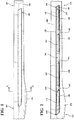
FIG 1 is a front view of an accent strip and a portion of a base structure of a vehicle according to an embodiment of the invention. -
FIG 2 is a front view ofFIG 1 , showing only the portion of the base structure. -
FIG 3 is enlarged view ofFIG 2 . -
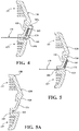
FIG 4 is a cross-sectional view ofFIG 1 taken along line A-A. -
FIG 5 is a cross-sectional view ofFIG 3 taken along line A-A. -
FIG 5A is a cross-sectional view ofFIG 3 taken along line B-B. -
FIG 6 is an enlarged perspective view of the accent molding and base structure during assembly. -
FIG 7 is a front view of a portion of the accent strip and base structure during assembly. -
FIG 8 is a cross-sectional view ofFIG 7 taken along line X-X. -
FIG 9 is a flow chart of a method of mounting an accent strip and a base structure. - Referring to the Figures, wherein like numerals indicate like or corresponding parts throughout the several views, a
base structure 100 according to an embodiment of the invention is shown. Directional references employed in the specification or claims, such as top, bottom, upper, lower, front, rear, first, second, right, left and the like, are employed for ease of description and are not intended to limit the scope of the invention. It will be appreciated that the structures and methods described herein may be used in various orientations. - Described herein is a base structure for a vehicle molding which supports a rigid accent strip, such as a metal or metal plated accent strip, with the use of an adhesive tape. Specifically, a
base structure 100 for a vehicle molding and anaccent strip 105 are illustrated inFIG 1 . Thebase structure 100 is typically made of plastic and may be a molding which is attached to a vehicle (not shown) for decorative or other purposes. In some embodiments, thebase structure 100 is part of the vehicle. Theaccent strip 105 may be made of metal or chrome plated plastic. In some embodiments, theaccent strip 105 may be made of other materials, such as a rigid plastic. Due in part to its rigidity, theaccent strip 105 cannot be mounted to a traditional base structure (not shown) by traditional means. Thebase structure 100 described herein also conceals designed thermal gaps, unwanted misalignments between theaccent strip 105 and thebase structure 100, and sharp ends or edges of theaccent strip 105. - The
base structure 100 is an elongate structure having afirst end 110 and asecond end 115. As illustrated inFIGS 2 to 6 , thebase structure 100 defines two grooves, a topelongate groove 120 and a bottomelongate groove 125 in an outward facingsurface 130 between the first andsecond ends middle portion 135 of thebase structure 100 extends from thetop groove 120 to thebottom groove 125. The top andbottom grooves accent strip 105 which is mounted to and supported by themiddle portion 135, as described in further detail below. - In some embodiments, the
base structure 100 defines afirst opening 140 in thefirst end 110 of thebase structure 100 and asecond opening 145 in thesecond end 115. In some embodiments, theopenings bottom grooves FIG 2 , thefirst opening 140 terminates the top andbottom grooves first end 110 of the base structure, and thesecond opening 145 terminates the top andbottom grooves second end 115 of the base structure. The first andsecond openings accent strip 105, as described in further detail below. For reference herein, the remaining portion of thebase structure 100 beyond or outside of the top andbottom grooves second openings outer portion 150 of thebase structure 100. Thebase structure 100 and theouter portion 150 may be generally any size and shape desired for the vehicle molding. - The
middle portion 135 of thebase structure 100 has an outward facingsurface 155. In some embodiments, as can be seen inFIGS 4 and 5 , themiddle portion 135 and outward facingsurface 155 are recessed and sit below the outward facingsurface 130 of theouter portion 140 of thebase structure 100. As a result, once theaccent strip 105 is mounted to thebase structure 100, theaccent strip 105 may be flush with or recessed slightly below the outward facingsurface 130. Thus, theaccent strip 105 may be protected by thebase structure 100. In some embodiments, theouter portion 150, or themiddle portion 135, or both theouter portion 150 and themiddle portion 135 of thebase structure 100 may be angled to provide the desired outward appearance and shape for the vehicle molding. In some embodiments, thebase structure 100 may include one or more bosses, ribs, flanges, or combinations thereof, to ensure that theaccent strip 105 is offset from the vehicle surface (not shown). An example ofribs 157 extending from the inward facing surface or inner side of thebase structure 100 can been seen inFIGS 4, 5 and 5A . The spacing created by theribs 157 ensures that any sharp ends or edges of theaccent strip 105 do not scratch of damage the surface of the vehicle to which thebody structure 100 is mounted. It will be appreciated that the outward facingsurface 130 of thebase structure 100, and the outward facingsurface 155 of themiddle portion 135, refer to the side of thebase structure 100 displaying theaccent strip 105. - The
middle portion 135 includes one or more areas or regions on the outward facingsurface 155, referred to herein asadhesive regions 160, to which an adhesive may be applied for fastening theaccent strip 105 to thebase structure 100. The adhesive may comprise anadhesive foam tape 165 having aremovable liner 170. For illustration purposes, multiple sections ofadhesive tape 165 are shown inFIG 2 with theremovable liner 170 removed from all sections except the section ofadhesive tape 165 adjacent thesecond end 115 of thebase structure 100. Theremovable liner 170 is used to conceal the adhesive component and prevent early sticking or bonding of theaccent strip 105 to thebase structure 100 during assembly. A leadingportion 175 of theliner 170 may be removed from a small portion of theadhesive tape 165 during the mounting of theaccent strip 105 to thebase structure 100, as described below. - As illustrated in
FIGS 4 and6 , theaccent strip 105 has two opposing side walls, 180a, 180b which extend from a middleaccent strip portion 185. Eachside wall side wall side wall 180a is received within thetop groove 120 and oneside wall 180b is received within thebottom groove 125. In some embodiments, theside walls accent strip portion 185. The middleaccent strip portion 185 is adhered to and supported by themiddle portion 135 of thebase structure 100. - Traditional mounting methods and base structures may result in the
accent strip 105 being moved out of position resulting in aesthetic mis-alignment and/or damaging thebase structure 100. Theremovable liner 170 of theadhesive tape 165 cannot be removed before theaccent strip 105 is placed into position since adhesion of theaccent strip 105 may occur prematurely. Due to theside walls accent strip 105, and thegrooves base structure 100, theremovable liner 170 of theadhesive tape 165 cannot be removed from the top. Theliner 170 also cannot be removed from the right or left side of this configuration (that is, from thefirst end 110 or thesecond end 115 of the base structure 100) without exhibiting tearing or stretching of theliner 170. To address these issues, thebase structure 100 includes additional structural features for use when mounting theaccent strip 105. - At least one
slot 190 is defined by thebase structure 100 in thetop groove 120 or thebottom groove 125 to allow theliner 170 to be passed through theslot 190 as it is removed from theadhesive tape 165. In one embodiment, oneslot 190 is defined in one of thetop groove 120 or thebottom groove 125 adjacent eachadhesive area 160. Theslot 190 has a width greater than the thickness of theliner 170 and thus, theliner 170 may pass through theslot 190 as theliner 170 is removed from theadhesive tape 165. In some embodiments, the width of theslot 190 is greater than the thickness of theliner 170 but smaller than the width of theside wall 180b. Theslots 190 allow the assembler to access and pull the sections of theliner 170 from the inward facing or back side of thebase structure 100 rather than from the right or left side. Theliner 170 thus can be safely peeled while exposing the acrylic adhesive portion of thetape 165. - The
slots 190 may be defined in thetop groove 120, thebottom groove 125, or combinations of the top andbottom grooves slots 190 may be based on the geometry of thebase structure 100 andaccent strip 105, and the desired direction for a vehicle production assembler to pull and remove theliner 170 from theadhesive tape 165. Eachslot 190 may extend exactly the length of theadhesive region 160 andadhesive tape 165. In other embodiments, theslot 190 may extend slightly beyond one or both ends of theadhesive area 160 andadhesive tape 165 as shown inFIG 3 . In some embodiments, as illustrated inFIGS 3 , and5A discrete slots 190 may be spaced along thebase structure 100 within thebottom groove 125 and separated bybridge areas 195. Thebridge areas 195 serve to maintain the thickness of thebase structure 100 and connections between themiddle portion 135 andouter portion 150 in order to maintain the structural rigidity and strength of thebase structure 100. In other embodiments (not shown) each slot may extend along the length of multipleadhesive regions 160, or one long slot may be provided in thetop groove 120 orbottom groove 125 to accommodate the removal of all of the sections ofliner 170. - The
middle portion 135 of thebase structure 100 also defines at least oneaperture 200 which may be used by the assembler when mounting theaccent strip 105 to thebase structure 100. In some embodiments, particularly if themiddle portion 135 of thebase structure 100 is recessed below the outward facingsurface 130, not enough space is available for an assembler to hold and handle theaccent strip 105 before it is secured to thebase structure 100. Theaperture 200 allows the assembler to hold and move theaccent strip 105 along the length of thebase structure 100 into the correct position between thefirst end 110 and thesecond end 115. Theaperture 200 is sized to provide enough space for an assembler's hand, fingers, or tool to hold and move theaccent strip 105. In one embodiment, theaperture 200 extends from thetop groove 120 to thebottom groove 125. Theaperture 200 also may be positioned adjacent one or moreadhesive regions 160 to allow the assembler to best control the position of theaccent strip 105. For example, as shown inFIG 2 , theaperture 200 is positioned in the centre of themiddle portion 135 between the centre twoadhesive regions 160. -
FIGS 7 and 8 are close up and cross-sectional views, respectively, of thesecond end 115 of thebase structure 100 and thesecond opening 145 during mounting of theaccent strip 105. Amethod 300 of mounting theaccent strip 105 to thebase structure 100 is set out in the flowchart ofFIG 9 . Specifically, to attach theaccent strip 105 to thebase structure 100, the method includes removing (action 310) a leadingportion 175 of theliner 170 and threading (action 315) the leadingportion 175 through theadjacent slot 190. These actions are repeated for each section ofadhesive tape 165 andliner 170 which will be covered by theaccent strip 105. As shown inFIGS 2 and3 , just a small corner of theliner 170 may be folded at the corner edge of theadhesive tape 165. Since only a small portion of theadhesive tape 165 is exposed, the chances of early sticking or bonding of theaccent strip 105 to thebase structure 100 are greatly reduced. In some embodiments, themethod 300 may include an assembler first measuring, cutting and applying sections ofadhesive tape 165 andliner 170 to theadhesive regions 160 of themiddle portion 135 of thebase structure 100. - The
method 300 includes placing (action 320) theaccent strip 105 in thebase structure 100. In some embodiments, placing theaccent strip 105 involves setting theside walls accent strip 105 into the corresponding top andbottom grooves accent strip 105 may then be supported and moved by an assembler through the use of theaperture 200 in order to align (action 325) theaccent strip 105 into its correct final position in thebase structure 100. Thebase structure 100 may include marked positions on its back or inner surface (not shown) to assist with the correct alignment of theaccent strip 105. - In other embodiments, the
base structure 100 includes first andsecond openings accent strip 105. This hides and conceals unwanted misalignments between theaccent strip 105 and thebase structure 100. Any cosmetic imperfections at the ends of theaccent strip 105, particularly the sharps ends of ametal accent strip 105, are also concealed behind thebase structure 100. As well, for ametal accent strip 105, with the ends tucked in and nested inside thebase structure 100 through the first andsecond openings metal accent strip 105 is trapped, thus preventing unwanted gapping and separation of theadhesive tape 165 between theaccent strip 105 and thebase structure 100. For this embodiment, placing (action 320) theaccent strip 105 in thebase structure 100 includes inserting each end of theaccent strip 105 into the first andsecond openings base structure 100. Specifically, with reference toFIG 8 , one end, such as asecond end 350 of theaccent strip 105 is inserted into thesecond opening 145. Theaccent strip 105 is allowed to rotate, as shown by dashed lines inFIG 8 , into thegrooves accent strip 105 is in a proper position. As theaccent strip 105 is being rotated, an assembler supports or holds theaccent strip 105 through theaperture 200 and slides or moves the first end (not shown) of theaccent strip 105 into thefirst opening 140 of the base structure. In other words, one end of theaccent strip 105 may be over-inserted into one of theopenings accent strip 105 is rotated and moved into place through the use of theaperture 200 to conceal the opposite end of theaccent strip 105 into the other opening of thebase structure 100. Theaccent strip 105 is thus aligned (action 325) into thebase structure 100. As illustrated inFIG 8 , themiddle portion 135 of thebase structure 100 may include a bevelled end to facilitate mounting of theaccent strip 105. - Once the
accent strip 105 is placed and aligned into the proper position in thebase structure 100, themethod 300 includes removing (action 330) the remaining portions of theliner 170 for each section ofadhesive tape 165. This is achieved by an assembler pulling the leadingportions 175 of theliner 170 and removing the remaining portions through theslots 190. Themethod 300 ends with the assembler adhering (action 335) theaccent strip 105 to thebase structure 100, such as by pressing on themiddle portion 185 of theaccent strip 105 to ensure that it adheres properly to the sections ofadhesive tape 165.
Claims (15)
- An elongate base structure (100) for receiving an accent strip (105) for a vehicle molding, the elongate base structure (100) comprising:an outward facing surface (130);top and bottom elongate grooves (120, 125) defined in the outward facing surface (130);a middle base portion (135) between the top and bottom grooves (120, 125), the middle base portion (135) having an outward facing surface (155) with at least one adhesive region (160) for receiving an adhesive;at least one slot (190) defined in one of the top groove (120) or the bottom groove (125), the at least one slot (190) being adjacent to and extending along the at least one adhesive region (160) of the middle base portion (135);characterized by an aperture (200) defined by middle base portion (135), between the top and bottom grooves (120, 125), wherein the aperture (200) allows an assembler to hold and move the accent strip (105).
- The elongate base structure (100) of claim 1, wherein the base structure (100) further comprises:a first end (110);a second end (115);a first opening (140) defined by the base structure (100), the first opening (140) terminating the top and bottom grooves (120, 125) adjacent the first end (110); anda second opening (145) defined by the base structure (100), the second opening (145) terminating the top and bottom grooves (120, 125) adjacent the second end (115).
- The elongate base structure (100) of claim 1, wherein the outward facing surface (155) of the middle base portion (135) is recessed below the outward facing surface (155) of the base structure (100).
- The elongate base structure (100) of claim 1, where the aperture (200) is adjacent one of the at least one adhesive regions (160), or
wherein the aperture (200) extends from the top groove to the bottom groove (120, 125). - The elongate base structure (100) of claim 1, wherein the at least one slot (190) extends beyond each end of the at least one adjacent adhesive region (160).
- The elongate base structure (100) of claim 1, comprising four adhesive regions (160) and four slots (190) spaced along the length of the base structure (100), and wherein the aperture (200) is defined by the middle base portion (135) between the middle two adhesive regions and slots.
- The elongate base structure (100) of claim 1, further comprising an adhesive tape (165) fastened to the at least one adhesive region (160) and the adhesive tape (165) having a removable liner (170), wherein the width of the slot (190) adjacent the at least one adhesive region (160) is greater than the thickness of the removable liner (170).
- The elongate base structure (100) of claim 7, further comprising the accent strip (105), the accent strip (105) having:two opposing side walls (180a, 180b) nested within the respective top and bottom elongate grooves (120, 125), anda middle accent strip portion (185) extending between the two side walls, the middle accent strip portion (185) being mounted to the middle base portion with adhesive.
- The elongate base structure (100) of claim 2, further comprising an adhesive tape fastened to the at least one adhesive region and the adhesive tape having a removable liner, wherein the width of the slot adjacent the at least one adhesive region is greater than the thickness of the removable liner.
- The elongate base structure (100) of claim 9, further comprising the accent strip (105), the accent strip (105) having:two opposing side walls nested within the respective top and bottom elongate grooves,a first end extending through first opening defined by the base structure (100),a second end extending through second opening defined by the base structure (100), anda middle accent strip portion (185) extending between the two side walls, the middle accent strip portion (185) being mounted to the middle base portion (135) with adhesive.
- The elongate base structure (100) of claim 8 or claim 10, wherein the side wall of the accent strip (105) which is nested within the bottom elongate groove (125) has a width greater than the width of the slot (190).
- The elongate base structure (100) of any one of claims 1 to 11, wherein the accent strip (105) comprises metal or chrome plated plastic.
- The elongate base structure (100) of any one of claims 1 to 12, further comprising one or more ribs, bosses, flanges, or combinations thereof extending from an inward facing of the base structure (100).
- A method of mounting an accent strip (105) for a vehicle to an elongate base structure (100), the elongate base structure (100) having an outward facing surface (130); top and bottom elongate grooves (120, 125) defined in the outward facing surface (130); a middle base portion (135) between the top and bottom grooves (120, 125), the middle base portion (135) having an outward facing surface (155) with at least one adhesive region (160) for receiving an adhesive tape (165) having a removable liner (170); at least one slot (190) defined in one of the top groove (120) or the bottom groove (125), the at least one slot (190) being adjacent to and extending along the at least one adhesive region (160) of the middle base portion (135); and the middle base portion (135) defining an aperture (200) adjacent one of the at least one adhesive regions (160), the method comprising:removing a leading portion (175) of the removable liner of the adhesive tape;threading the leading portion (175) of the removable liner (170) through the slot (190);placing the accent strip (105) within the grooves of the elongate base structure (100);aligning the accent strip (105) within the elongate base structure (100) using the aperture;removing a remaining portion of the removable liner (170) using the leading portion (175); andpressing the accent strip (105) against the middle base portion (135) to secure the accent strip (105) to the elongate base structure (100).
- The method of claim 14 wherein the elongate base structure (100) further defines a first opening (140) terminating the top and bottom grooves (120, 125) adjacent the first end (110), and a second opening (145) terminating the top and bottom grooves (120, 125) adjacent the second end (115), and wherein placing the accent strip (105) within the grooves (120, 125) of the elongate base structure (100) comprises:inserting a first end of the accent strip (105) into the first opening (140) of the base structure (100); androtating and sliding the accent strip (105) to insert a second end of the accent strip (105) into the second opening (145).
Applications Claiming Priority (2)
| Application Number | Priority Date | Filing Date | Title |
|---|---|---|---|
| US201662367662P | 2016-07-28 | 2016-07-28 | |
| PCT/CA2017/050909 WO2018018157A1 (en) | 2016-07-28 | 2017-07-28 | Body molding and method of applying an accent strip to a body molding |
Publications (3)
| Publication Number | Publication Date |
|---|---|
| EP3490847A1 EP3490847A1 (en) | 2019-06-05 |
| EP3490847A4 EP3490847A4 (en) | 2020-01-15 |
| EP3490847B1 true EP3490847B1 (en) | 2021-01-27 |
Family
ID=61015639
Family Applications (1)
| Application Number | Title | Priority Date | Filing Date |
|---|---|---|---|
| EP17833158.3A Active EP3490847B1 (en) | 2016-07-28 | 2017-07-28 | Body molding and method of applying an accent strip to a body molding |
Country Status (6)
| Country | Link |
|---|---|
| US (1) | US11091104B2 (en) |
| EP (1) | EP3490847B1 (en) |
| BR (1) | BR112019001560A2 (en) |
| CA (1) | CA3031989A1 (en) |
| MX (1) | MX2019001143A (en) |
| WO (1) | WO2018018157A1 (en) |
Families Citing this family (2)
| Publication number | Priority date | Publication date | Assignee | Title |
|---|---|---|---|---|
| DE102021130195B4 (en) * | 2021-11-18 | 2025-02-20 | Bayerische Motoren Werke Aktiengesellschaft | composite for an exterior panel of a motor vehicle |
| USD1118440S1 (en) * | 2024-09-06 | 2026-03-17 | Chenyi Tan | Automobile door protection strip |
Family Cites Families (27)
| Publication number | Priority date | Publication date | Assignee | Title |
|---|---|---|---|---|
| US3441305A (en) * | 1966-11-23 | 1969-04-29 | Earl M Trammell Jr | Resilient bumper strip |
| US3745056A (en) * | 1971-04-05 | 1973-07-10 | Standard Products Co | Trim strip structure |
| US3777438A (en) * | 1971-08-30 | 1973-12-11 | R Brown | Ornamental protective rail |
| US3881042A (en) * | 1973-10-03 | 1975-04-29 | Standard Products Co | Adhesive barrier for plastic trim strip |
| US3959537A (en) * | 1974-03-06 | 1976-05-25 | The Standard Products Company | Dielectrically bondable decorative strips |
| US3982780A (en) * | 1975-04-21 | 1976-09-28 | Minnesota Mining And Manufacturing Company | Conformable plastic body side molding |
| US4296155A (en) * | 1979-10-16 | 1981-10-20 | Madonia Ciro N | Overcoated decorative moulding |
| JPS58133940A (en) * | 1982-02-01 | 1983-08-09 | Nissan Motor Co Ltd | Molding structure for car |
| US4446179A (en) * | 1982-05-21 | 1984-05-01 | The D. L. Auld Company | Trim strip for automobile bodies |
| DE3502056A1 (en) * | 1985-01-23 | 1986-07-24 | Hilmar 5630 Remscheid Herrmann | Water protection coating for covering vehicle body parts to protect against moisture penetrating into the passenger compartment from outside |
| FR2665129B1 (en) * | 1990-07-24 | 1992-11-06 | Peugeot | DEVICE FOR FIXING BY ADHESIVE A TRIM ON AN ELEMENT, SUCH AS FOR example A VEHICLE ROOF. |
| US5188408A (en) * | 1991-08-08 | 1993-02-23 | Karl Berdan | Mechanical lock for vehicle trim panels and the like |
| US6318045B1 (en) * | 1992-03-27 | 2001-11-20 | Ronald D. Kress | Clip for mounting molding |
| US5783020A (en) * | 1996-01-04 | 1998-07-21 | Ronald D. Kress | Mounting clip |
| US5662758A (en) * | 1996-01-10 | 1997-09-02 | The Procter & Gamble Company | Composite material releasably sealable to a target surface when pressed thereagainst and method of making |
| DE19616958A1 (en) * | 1996-04-27 | 1996-12-12 | Daimler Benz Ag | Covering for bumper of motor vehicles |
| JP3511920B2 (en) * | 1998-11-27 | 2004-03-29 | 豊田合成株式会社 | Decorative tape sticking mall |
| FR2796020B1 (en) * | 1999-07-06 | 2001-09-14 | Plastic Omnium Cie | BUMPER HEADBAND AND BUMPER PROVIDED WITH SUCH A HEADBAND |
| DE10200891B4 (en) | 2002-01-11 | 2017-06-29 | Volkswagen Ag | Trim arrangement for a vehicle, in particular for a motor vehicle |
| DE10216128A1 (en) | 2002-04-12 | 2003-11-06 | Daimler Chrysler Ag | Car chassis or bodywork has functional or ornamental component, e.g. trim strip, mounted on it by fitting lips on component into grooves (13, 15) in the chassis or bodywork |
| US20050181173A1 (en) * | 2003-12-16 | 2005-08-18 | Hermann Stephan M. | Angled ribs for plastic part attachment for vehicles |
| US20070085361A1 (en) * | 2005-10-19 | 2007-04-19 | Christian Hauser | Injection molded parts for vehicles and other devices |
| MX2008014916A (en) | 2006-05-25 | 2009-01-09 | Johnson Controls Tech Co | Molded article including decorative element and method of attaching a decorative element to a vehicle component. |
| US7517001B1 (en) * | 2007-02-20 | 2009-04-14 | Harold Goldbaum | Trim system for vehicle bumpers, doors and panels |
| DE102009017363A1 (en) * | 2009-04-14 | 2010-10-28 | Daimler Ag | Decorative element and method for its production and method for its activation |
| JP6883940B2 (en) * | 2015-10-09 | 2021-06-09 | スリーエム イノベイティブ プロパティズ カンパニー | Goods, how to make goods, how to attach goods |
| JP6410784B2 (en) * | 2016-12-06 | 2018-10-24 | 本田技研工業株式会社 | Car body structure and decorative member |
-
2017
- 2017-07-28 WO PCT/CA2017/050909 patent/WO2018018157A1/en not_active Ceased
- 2017-07-28 US US16/319,926 patent/US11091104B2/en active Active
- 2017-07-28 BR BR112019001560-4A patent/BR112019001560A2/en not_active Application Discontinuation
- 2017-07-28 MX MX2019001143A patent/MX2019001143A/en unknown
- 2017-07-28 EP EP17833158.3A patent/EP3490847B1/en active Active
- 2017-07-28 CA CA3031989A patent/CA3031989A1/en active Pending
Non-Patent Citations (1)
| Title |
|---|
| None * |
Also Published As
| Publication number | Publication date |
|---|---|
| EP3490847A4 (en) | 2020-01-15 |
| EP3490847A1 (en) | 2019-06-05 |
| CA3031989A1 (en) | 2018-02-01 |
| WO2018018157A1 (en) | 2018-02-01 |
| MX2019001143A (en) | 2019-09-09 |
| US20190263333A1 (en) | 2019-08-29 |
| BR112019001560A2 (en) | 2019-05-14 |
| US11091104B2 (en) | 2021-08-17 |
Similar Documents
| Publication | Publication Date | Title |
|---|---|---|
| EP3140177B1 (en) | Roof attachment method for an applied composition roof | |
| US8322110B2 (en) | Trim flap-like closeout edge attachment | |
| US4308704A (en) | Trim molding | |
| EP2755866B1 (en) | Weatherstrip assembly having a removable retaining member | |
| US11091104B2 (en) | Body molding and method of applying an accent strip to a body molding | |
| US7597371B2 (en) | Lead-in for trim assembly | |
| CN101132937B (en) | Internal panel of automobile equipped with sunshine shading device | |
| US8251440B2 (en) | Multi-segmented headliner having longitudinal joint | |
| US11167707B2 (en) | Front fascia assembly for a vehicle | |
| EP2604870A2 (en) | An integrated clip | |
| CN100467331C (en) | fender structure | |
| TWI590961B (en) | Pleated blinds between a-pillars of a car | |
| US20210101541A1 (en) | Front fascia for a vehicle | |
| GB2173845A (en) | Weatherstrip | |
| JP4800293B2 (en) | Convertible top cover attachment system | |
| US11059523B2 (en) | Adjustable datum pin assembly for temporarily securing a vehicle component to a vehicle structure | |
| JPH07257289A (en) | Decoration fitting structure in automobile interior part | |
| GB2535317A (en) | Panel configured to be attached to an outside of a vehicle component, arrangement of a panel and method for attaching a panel | |
| US20200010026A1 (en) | Snap-on cover for vehicle door handle | |
| JPS5848166Y2 (en) | Mounting structure for automotive decorative parts | |
| US11623588B2 (en) | Method and apparatus for fastening hard and soft top appliques | |
| KR20030038359A (en) | Fastener for joining two members | |
| CN116021990A (en) | A sub-dashboard assembly and a vehicle | |
| EP2708690A2 (en) | Interior handle for opening the door of a motor vehicle | |
| JP7021555B2 (en) | Vehicle interior |
Legal Events
| Date | Code | Title | Description |
|---|---|---|---|
| STAA | Information on the status of an ep patent application or granted ep patent |
Free format text: STATUS: THE INTERNATIONAL PUBLICATION HAS BEEN MADE |
|
| PUAI | Public reference made under article 153(3) epc to a published international application that has entered the european phase |
Free format text: ORIGINAL CODE: 0009012 |
|
| STAA | Information on the status of an ep patent application or granted ep patent |
Free format text: STATUS: REQUEST FOR EXAMINATION WAS MADE |
|
| 17P | Request for examination filed |
Effective date: 20190205 |
|
| AK | Designated contracting states |
Kind code of ref document: A1 Designated state(s): AL AT BE BG CH CY CZ DE DK EE ES FI FR GB GR HR HU IE IS IT LI LT LU LV MC MK MT NL NO PL PT RO RS SE SI SK SM TR |
|
| AX | Request for extension of the european patent |
Extension state: BA ME |
|
| DAV | Request for validation of the european patent (deleted) | ||
| DAX | Request for extension of the european patent (deleted) | ||
| A4 | Supplementary search report drawn up and despatched |
Effective date: 20191213 |
|
| RIC1 | Information provided on ipc code assigned before grant |
Ipc: B62D 65/02 20060101ALI20191209BHEP Ipc: B60R 13/02 20060101AFI20191209BHEP |
|
| GRAP | Despatch of communication of intention to grant a patent |
Free format text: ORIGINAL CODE: EPIDOSNIGR1 |
|
| STAA | Information on the status of an ep patent application or granted ep patent |
Free format text: STATUS: GRANT OF PATENT IS INTENDED |
|
| INTG | Intention to grant announced |
Effective date: 20200914 |
|
| GRAS | Grant fee paid |
Free format text: ORIGINAL CODE: EPIDOSNIGR3 |
|
| GRAA | (expected) grant |
Free format text: ORIGINAL CODE: 0009210 |
|
| STAA | Information on the status of an ep patent application or granted ep patent |
Free format text: STATUS: THE PATENT HAS BEEN GRANTED |
|
| AK | Designated contracting states |
Kind code of ref document: B1 Designated state(s): AL AT BE BG CH CY CZ DE DK EE ES FI FR GB GR HR HU IE IS IT LI LT LU LV MC MK MT NL NO PL PT RO RS SE SI SK SM TR |
|
| REG | Reference to a national code |
Ref country code: GB Ref legal event code: FG4D |
|
| REG | Reference to a national code |
Ref country code: CH Ref legal event code: EP |
|
| REG | Reference to a national code |
Ref country code: AT Ref legal event code: REF Ref document number: 1358064 Country of ref document: AT Kind code of ref document: T Effective date: 20210215 |
|
| REG | Reference to a national code |
Ref country code: IE Ref legal event code: FG4D |
|
| REG | Reference to a national code |
Ref country code: DE Ref legal event code: R096 Ref document number: 602017032255 Country of ref document: DE |
|
| REG | Reference to a national code |
Ref country code: CH Ref legal event code: NV Representative=s name: VALIPAT S.A. C/O BOVARD SA NEUCHATEL, CH |
|
| REG | Reference to a national code |
Ref country code: NL Ref legal event code: MP Effective date: 20210127 |
|
| REG | Reference to a national code |
Ref country code: LT Ref legal event code: MG9D |
|
| REG | Reference to a national code |
Ref country code: AT Ref legal event code: MK05 Ref document number: 1358064 Country of ref document: AT Kind code of ref document: T Effective date: 20210127 |
|
| PG25 | Lapsed in a contracting state [announced via postgrant information from national office to epo] |
Ref country code: LT Free format text: LAPSE BECAUSE OF FAILURE TO SUBMIT A TRANSLATION OF THE DESCRIPTION OR TO PAY THE FEE WITHIN THE PRESCRIBED TIME-LIMIT Effective date: 20210127 Ref country code: BG Free format text: LAPSE BECAUSE OF FAILURE TO SUBMIT A TRANSLATION OF THE DESCRIPTION OR TO PAY THE FEE WITHIN THE PRESCRIBED TIME-LIMIT Effective date: 20210427 Ref country code: FI Free format text: LAPSE BECAUSE OF FAILURE TO SUBMIT A TRANSLATION OF THE DESCRIPTION OR TO PAY THE FEE WITHIN THE PRESCRIBED TIME-LIMIT Effective date: 20210127 Ref country code: GR Free format text: LAPSE BECAUSE OF FAILURE TO SUBMIT A TRANSLATION OF THE DESCRIPTION OR TO PAY THE FEE WITHIN THE PRESCRIBED TIME-LIMIT Effective date: 20210428 Ref country code: HR Free format text: LAPSE BECAUSE OF FAILURE TO SUBMIT A TRANSLATION OF THE DESCRIPTION OR TO PAY THE FEE WITHIN THE PRESCRIBED TIME-LIMIT Effective date: 20210127 Ref country code: NO Free format text: LAPSE BECAUSE OF FAILURE TO SUBMIT A TRANSLATION OF THE DESCRIPTION OR TO PAY THE FEE WITHIN THE PRESCRIBED TIME-LIMIT Effective date: 20210427 Ref country code: PT Free format text: LAPSE BECAUSE OF FAILURE TO SUBMIT A TRANSLATION OF THE DESCRIPTION OR TO PAY THE FEE WITHIN THE PRESCRIBED TIME-LIMIT Effective date: 20210527 |
|
| PG25 | Lapsed in a contracting state [announced via postgrant information from national office to epo] |
Ref country code: AT Free format text: LAPSE BECAUSE OF FAILURE TO SUBMIT A TRANSLATION OF THE DESCRIPTION OR TO PAY THE FEE WITHIN THE PRESCRIBED TIME-LIMIT Effective date: 20210127 Ref country code: LV Free format text: LAPSE BECAUSE OF FAILURE TO SUBMIT A TRANSLATION OF THE DESCRIPTION OR TO PAY THE FEE WITHIN THE PRESCRIBED TIME-LIMIT Effective date: 20210127 Ref country code: PL Free format text: LAPSE BECAUSE OF FAILURE TO SUBMIT A TRANSLATION OF THE DESCRIPTION OR TO PAY THE FEE WITHIN THE PRESCRIBED TIME-LIMIT Effective date: 20210127 Ref country code: RS Free format text: LAPSE BECAUSE OF FAILURE TO SUBMIT A TRANSLATION OF THE DESCRIPTION OR TO PAY THE FEE WITHIN THE PRESCRIBED TIME-LIMIT Effective date: 20210127 Ref country code: SE Free format text: LAPSE BECAUSE OF FAILURE TO SUBMIT A TRANSLATION OF THE DESCRIPTION OR TO PAY THE FEE WITHIN THE PRESCRIBED TIME-LIMIT Effective date: 20210127 |
|
| PG25 | Lapsed in a contracting state [announced via postgrant information from national office to epo] |
Ref country code: IS Free format text: LAPSE BECAUSE OF FAILURE TO SUBMIT A TRANSLATION OF THE DESCRIPTION OR TO PAY THE FEE WITHIN THE PRESCRIBED TIME-LIMIT Effective date: 20210527 |
|
| REG | Reference to a national code |
Ref country code: DE Ref legal event code: R097 Ref document number: 602017032255 Country of ref document: DE |
|
| PG25 | Lapsed in a contracting state [announced via postgrant information from national office to epo] |
Ref country code: SM Free format text: LAPSE BECAUSE OF FAILURE TO SUBMIT A TRANSLATION OF THE DESCRIPTION OR TO PAY THE FEE WITHIN THE PRESCRIBED TIME-LIMIT Effective date: 20210127 Ref country code: EE Free format text: LAPSE BECAUSE OF FAILURE TO SUBMIT A TRANSLATION OF THE DESCRIPTION OR TO PAY THE FEE WITHIN THE PRESCRIBED TIME-LIMIT Effective date: 20210127 Ref country code: CZ Free format text: LAPSE BECAUSE OF FAILURE TO SUBMIT A TRANSLATION OF THE DESCRIPTION OR TO PAY THE FEE WITHIN THE PRESCRIBED TIME-LIMIT Effective date: 20210127 |
|
| PG25 | Lapsed in a contracting state [announced via postgrant information from national office to epo] |
Ref country code: SK Free format text: LAPSE BECAUSE OF FAILURE TO SUBMIT A TRANSLATION OF THE DESCRIPTION OR TO PAY THE FEE WITHIN THE PRESCRIBED TIME-LIMIT Effective date: 20210127 Ref country code: RO Free format text: LAPSE BECAUSE OF FAILURE TO SUBMIT A TRANSLATION OF THE DESCRIPTION OR TO PAY THE FEE WITHIN THE PRESCRIBED TIME-LIMIT Effective date: 20210127 Ref country code: DK Free format text: LAPSE BECAUSE OF FAILURE TO SUBMIT A TRANSLATION OF THE DESCRIPTION OR TO PAY THE FEE WITHIN THE PRESCRIBED TIME-LIMIT Effective date: 20210127 |
|
| PLBE | No opposition filed within time limit |
Free format text: ORIGINAL CODE: 0009261 |
|
| STAA | Information on the status of an ep patent application or granted ep patent |
Free format text: STATUS: NO OPPOSITION FILED WITHIN TIME LIMIT |
|
| 26N | No opposition filed |
Effective date: 20211028 |
|
| PG25 | Lapsed in a contracting state [announced via postgrant information from national office to epo] |
Ref country code: ES Free format text: LAPSE BECAUSE OF FAILURE TO SUBMIT A TRANSLATION OF THE DESCRIPTION OR TO PAY THE FEE WITHIN THE PRESCRIBED TIME-LIMIT Effective date: 20210127 Ref country code: AL Free format text: LAPSE BECAUSE OF FAILURE TO SUBMIT A TRANSLATION OF THE DESCRIPTION OR TO PAY THE FEE WITHIN THE PRESCRIBED TIME-LIMIT Effective date: 20210127 |
|
| PG25 | Lapsed in a contracting state [announced via postgrant information from national office to epo] |
Ref country code: SI Free format text: LAPSE BECAUSE OF FAILURE TO SUBMIT A TRANSLATION OF THE DESCRIPTION OR TO PAY THE FEE WITHIN THE PRESCRIBED TIME-LIMIT Effective date: 20210127 |
|
| PG25 | Lapsed in a contracting state [announced via postgrant information from national office to epo] |
Ref country code: IT Free format text: LAPSE BECAUSE OF FAILURE TO SUBMIT A TRANSLATION OF THE DESCRIPTION OR TO PAY THE FEE WITHIN THE PRESCRIBED TIME-LIMIT Effective date: 20210127 |
|
| PG25 | Lapsed in a contracting state [announced via postgrant information from national office to epo] |
Ref country code: IS Free format text: LAPSE BECAUSE OF FAILURE TO SUBMIT A TRANSLATION OF THE DESCRIPTION OR TO PAY THE FEE WITHIN THE PRESCRIBED TIME-LIMIT Effective date: 20210527 |
|
| PG25 | Lapsed in a contracting state [announced via postgrant information from national office to epo] |
Ref country code: NL Free format text: LAPSE BECAUSE OF NON-PAYMENT OF DUE FEES Effective date: 20210127 Ref country code: CY Free format text: LAPSE BECAUSE OF FAILURE TO SUBMIT A TRANSLATION OF THE DESCRIPTION OR TO PAY THE FEE WITHIN THE PRESCRIBED TIME-LIMIT Effective date: 20210127 |
|
| PG25 | Lapsed in a contracting state [announced via postgrant information from national office to epo] |
Ref country code: HU Free format text: LAPSE BECAUSE OF FAILURE TO SUBMIT A TRANSLATION OF THE DESCRIPTION OR TO PAY THE FEE WITHIN THE PRESCRIBED TIME-LIMIT; INVALID AB INITIO Effective date: 20170728 |
|
| PGFP | Annual fee paid to national office [announced via postgrant information from national office to epo] |
Ref country code: LU Payment date: 20230719 Year of fee payment: 7 |
|
| PGFP | Annual fee paid to national office [announced via postgrant information from national office to epo] |
Ref country code: MC Payment date: 20230719 Year of fee payment: 7 Ref country code: IE Payment date: 20230726 Year of fee payment: 7 Ref country code: GB Payment date: 20230724 Year of fee payment: 7 Ref country code: CH Payment date: 20230801 Year of fee payment: 7 |
|
| PGFP | Annual fee paid to national office [announced via postgrant information from national office to epo] |
Ref country code: FR Payment date: 20230720 Year of fee payment: 7 Ref country code: DE Payment date: 20230726 Year of fee payment: 7 Ref country code: BE Payment date: 20230719 Year of fee payment: 7 |
|
| PGFP | Annual fee paid to national office [announced via postgrant information from national office to epo] |
Ref country code: MT Payment date: 20230721 Year of fee payment: 7 |
|
| PG25 | Lapsed in a contracting state [announced via postgrant information from national office to epo] |
Ref country code: MK Free format text: LAPSE BECAUSE OF FAILURE TO SUBMIT A TRANSLATION OF THE DESCRIPTION OR TO PAY THE FEE WITHIN THE PRESCRIBED TIME-LIMIT Effective date: 20210127 |
|
| REG | Reference to a national code |
Ref country code: DE Ref legal event code: R119 Ref document number: 602017032255 Country of ref document: DE |
|
| PG25 | Lapsed in a contracting state [announced via postgrant information from national office to epo] |
Ref country code: MC Free format text: LAPSE BECAUSE OF NON-PAYMENT OF DUE FEES Effective date: 20240731 |
|
| REG | Reference to a national code |
Ref country code: CH Ref legal event code: PL |
|
| PG25 | Lapsed in a contracting state [announced via postgrant information from national office to epo] |
Ref country code: LU Free format text: LAPSE BECAUSE OF NON-PAYMENT OF DUE FEES Effective date: 20240728 |
|
| GBPC | Gb: european patent ceased through non-payment of renewal fee |
Effective date: 20240728 |
|
| PG25 | Lapsed in a contracting state [announced via postgrant information from national office to epo] |
Ref country code: LU Free format text: LAPSE BECAUSE OF NON-PAYMENT OF DUE FEES Effective date: 20240728 |
|
| PG25 | Lapsed in a contracting state [announced via postgrant information from national office to epo] |
Ref country code: DE Free format text: LAPSE BECAUSE OF NON-PAYMENT OF DUE FEES Effective date: 20250201 |
|
| PG25 | Lapsed in a contracting state [announced via postgrant information from national office to epo] |
Ref country code: CH Free format text: LAPSE BECAUSE OF NON-PAYMENT OF DUE FEES Effective date: 20240731 Ref country code: BE Free format text: LAPSE BECAUSE OF NON-PAYMENT OF DUE FEES Effective date: 20240731 |
|
| PG25 | Lapsed in a contracting state [announced via postgrant information from national office to epo] |
Ref country code: FR Free format text: LAPSE BECAUSE OF NON-PAYMENT OF DUE FEES Effective date: 20240731 |
|
| PG25 | Lapsed in a contracting state [announced via postgrant information from national office to epo] |
Ref country code: GB Free format text: LAPSE BECAUSE OF NON-PAYMENT OF DUE FEES Effective date: 20240728 |
|
| REG | Reference to a national code |
Ref country code: BE Ref legal event code: MM Effective date: 20240731 |
|
| PG25 | Lapsed in a contracting state [announced via postgrant information from national office to epo] |
Ref country code: IE Free format text: LAPSE BECAUSE OF NON-PAYMENT OF DUE FEES Effective date: 20240728 |
|
| PG25 | Lapsed in a contracting state [announced via postgrant information from national office to epo] |
Ref country code: TR Free format text: LAPSE BECAUSE OF FAILURE TO SUBMIT A TRANSLATION OF THE DESCRIPTION OR TO PAY THE FEE WITHIN THE PRESCRIBED TIME-LIMIT Effective date: 20210127 |