EP2708690A2 - Interior handle for opening the door of a motor vehicle - Google Patents
Interior handle for opening the door of a motor vehicle Download PDFInfo
- Publication number
- EP2708690A2 EP2708690A2 EP13382329.4A EP13382329A EP2708690A2 EP 2708690 A2 EP2708690 A2 EP 2708690A2 EP 13382329 A EP13382329 A EP 13382329A EP 2708690 A2 EP2708690 A2 EP 2708690A2
- Authority
- EP
- European Patent Office
- Prior art keywords
- lever
- frame
- perimeter
- handle
- wall
- Prior art date
- Legal status (The legal status is an assumption and is not a legal conclusion. Google has not performed a legal analysis and makes no representation as to the accuracy of the status listed.)
- Granted
Links
- 238000005192 partition Methods 0.000 claims abstract description 34
- 238000010168 coupling process Methods 0.000 description 22
- 230000008878 coupling Effects 0.000 description 21
- 238000005859 coupling reaction Methods 0.000 description 21
- 238000000034 method Methods 0.000 description 5
- 238000007747 plating Methods 0.000 description 4
- 230000007547 defect Effects 0.000 description 3
- 238000000926 separation method Methods 0.000 description 3
- 238000004026 adhesive bonding Methods 0.000 description 1
- 238000005452 bending Methods 0.000 description 1
- 239000011248 coating agent Substances 0.000 description 1
- 238000000576 coating method Methods 0.000 description 1
- 230000003247 decreasing effect Effects 0.000 description 1
- 230000001419 dependent effect Effects 0.000 description 1
- 230000001771 impaired effect Effects 0.000 description 1
- 238000002347 injection Methods 0.000 description 1
- 239000007924 injection Substances 0.000 description 1
- 238000001746 injection moulding Methods 0.000 description 1
- 238000002955 isolation Methods 0.000 description 1
- 239000000463 material Substances 0.000 description 1
- 238000001465 metallisation Methods 0.000 description 1
- 238000010422 painting Methods 0.000 description 1
- 239000000243 solution Substances 0.000 description 1
Images


Classifications
-
- E—FIXED CONSTRUCTIONS
- E05—LOCKS; KEYS; WINDOW OR DOOR FITTINGS; SAFES
- E05B—LOCKS; ACCESSORIES THEREFOR; HANDCUFFS
- E05B79/00—Mounting or connecting vehicle locks or parts thereof
- E05B79/02—Mounting of vehicle locks or parts thereof
- E05B79/06—Mounting of handles, e.g. to the wing or to the lock
-
- E—FIXED CONSTRUCTIONS
- E05—LOCKS; KEYS; WINDOW OR DOOR FITTINGS; SAFES
- E05B—LOCKS; ACCESSORIES THEREFOR; HANDCUFFS
- E05B85/00—Details of vehicle locks not provided for in groups E05B77/00 - E05B83/00
- E05B85/10—Handles
- E05B85/12—Inner door handles
Definitions
- the invention herein is encompassed within the field of the automobile industry and more specifically relates to an interior handle for opening the door of a motor vehicle that is comprised of a lever that acts as a door handle, which is surrounded by an outer frame surrounding said lever and having a primarily decorative function.
- clipping systems are used for joining the various components of a car since they are simple couplings and relatively more economical compared to other similar solutions. More specifically, the clipping elements of the two components to be joined are usually moulded directly into one of said components.
- said handle is normally composed of a lever that is surrounded by a decorative frame that is usually chrome-plated in most cases.
- Joining the decorative frame to the lever can be done in many ways.
- said coupling can be made by means of scoring and clipping, which is the simplest method of attachment, and consists of using clips moulded directly into one of the two components to be joined.
- the decorative contour is an annular element that fits over the entire contour of the lever
- the clipping of the decorative contour on the lever has the drawback that the flanges are visible at the rear part of the lever and when the handle is actuated, the rear part can be seen by the user. Therefore, the coupling elements of the lever and the decorative frame have to be concealed.
- the clearance in other words, the degree of separation of the opposite outer perimeters of the lever and the frame is particularly noticeable once they have been once joined, mainly due to the defects of form of said components and due to the clearance required for the correct assembly thereof.
- clipping couplings are typically advised against if the quality requirements are high, such as for example the metallic and/or painted parts of a car.
- Patent WO 2011/032976 describes one such clipping system for the door handle of a vehicle; in this case the problem arises related to the space or clearance between the lever and the decorative frame, which is considerable, and the coupling can further be seen between both parts from the rear part of the lever and therefore it is visible to the user.
- the decorative frame can be divided into two more or less symmetrical parts, that are fixed on opposite sides, but in this case the groove of the coupling between the two parts would be visible and additionally when the chrome-plated decorative frame is inserted around the lever, its perimeter must be slightly increased in order to then insert it and the frame may become deformed or the chrome-plating may become damaged.
- a final option is to use bi-injection moulding as a method of forming the handle, which essentially consists of the coupling of the two materials (lever and decorative frame) by means of co-injection of the second over the first, and subsequently chrome-plating the decorative frame.
- This method has the disadvantage that, during the chrome-plating process, the surface of the part of the handle that is not plated becomes damaged. In addition, this process involves the presence of a clearance or space between the chrome-plated part and the lever.
- the invention herein relates to an interior handle for opening the door of a vehicle of the type that are hinged, in relation to a housing built into the interior trim panel of the vehicle door, the handle being included inside said housing in a rest position.
- the handle comprises a lever that has a front opening with a perimeter partition exteriorly surrounding the contour of the lever and an outer frame that, in turn, has a perimeter partition exteriorly facing the perimeter partition of the lever surrounding the frame exteriorly to the lever.
- a particular characteristic of the handle, object of the invention herein, is that the outer contour of the lever, on its face side, has a perimeter rim with its outer wall tapered in relation to the centre of the housing and the outer contour of the frame has a perimeter groove on its face side, directed towards the inside of the handle, with its tapered inner wall, the cone taper of said tapered inner wall of the frame and the cone taper of the tapered outer wall of the lever being coincident.
- a plurality of clipping points may be arranged on the outer face of the perimeter partition of the lever and on the inner face of the perimeter partition of the frame, in the immediate area surrounding the unseen faces opposite the visible faces and therefore further away from the perimeter rim of the lever and the perimeter groove of the frame and configured so as to exert pressure on the contact zone between the tapered inner wall of the frame and the tapered outer wall of the lever.
- the clipping strength required to maintain the conical contact between the lever and frame is determined by the interference values on the faces of the clips. Its function is to put pressure on the conical fit, such that perfect leveling is achieved between surfaces and in this way coupling defects are hidden, as there is no clearance between them.
- the clipping points are further away from the visible conical fit zones and that provides the flexibility necessary for efficient and easy assembly. Therefore, for metallic component couplings, for example, friction during assembly can be decreased in order for the coating not to get impaired.
- a plurality of guide zones may be arranged on the outer face of the perimeter partition of the lever and on the inner face of the perimeter partition of the frame, alternately to the clipping points, in the immediate area surrounding the unseen faces opposite the visible faces.
- the guide zones may comprise brackets, attached to the perimeter partition of the frame and grooves, made in the perimeter partition of the lever, whose position will be coincident with the position of the brackets, covering said brackets.
- the visible face of the frame may present a surface with a different appearance to the surface of the visible face of the lever.
- the surface finish of each one of the components, lever and frame, of the handle may be different.
- the frame may be chrome-plated and the lever may not be or vice versa.
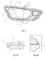
- the interior handle for opening the door, object of the invention herein is, in turn, connected to a housing 1 that houses it on the inside in a rest position or non-actuated condition thereof.
- the handles rotates in relation to the housing according to an axis of rotation that is vertical taking into account the normal assembly position of the aforementioned housing 1 in the interior trim panel (not shown) of the door.
- the handle has been shown in an actuated position or open position, in which the handle has rotated in relation to the housing 1.
- the handle consists essentially of two parts, firstly the lever 2, which, in this embodiment has an approximately trapezoidal shape with rounded corners and slightly curved edges. Said lever 2 is shown in isolation in Figure 8 and has a front opening 3, that is somewhat recessed relative to the front vertical imaginary plane (as mounted on the vehicle door) defined by the outer contour of the lever, said plane known as the "visible face” of the lever and the opposite rear part of the lever is called the "unseen face”.
- the lever is surrounded along the entire outer contour of a perimeter partition 4, which is perpendicular to the visible face of the lever.
- the handle comprises a decorative outer frame 5 having a similar shape to the lever 2 surrounding it, also having a perimeter partition 6 that is facing the perimeter partition 4 of the lever when the frame is mounted in said lever 2.
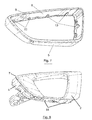
- Figure 3 shows the lever assembly 2 and the frame 5, and it can be seen how the frame surrounds the entire outer contour of the lever.
- the outer contour of the lever 2 has a perimeter rim 7 on the face side, with its outer wall 8 conically configured in relation to the centre of the housing 1, the outer contour of the frame 5 on the face side, having a perimeter groove 9 directed towards the inside of the handle, with its inner wall 10 also conically configured, the cone taper of said inner wall 10 of the frame 5 and the cone taper of the outer wall 8 of the lever 2 being coincident.
- This characteristic of the invention can be seen more clearly in the section of a part of the handle shown in Figures 4A and 4B .
- the coupling between the lever 2 and the outer frame 5 is achieved by means of clipping points 11, which are arranged on the outer face of the perimeter partition 4 of the lever 2 and on the inner face of the perimeter partition 6 of the frame 5. They are distributed along the entire contour of both components, in the immediate area surrounding its unseen sides, opposite the visible faces, and therefore further away from the perimeter rim 7 of the lever 2 and the perimeter groove 9 of the frame 5 and configured so as to exert pressure on the contact zone between the tapered inner wall 10 of the frame 5 and the tapered outer wall 8 of the lever 2.
- the arrangement of the clipping points is shown in Figure 3 , wherein said clipping points 11 have been surrounded with circles formed in broken lines for the purpose of clarity. In this manner, the separation between the lever 2 and the frame 5 on the front visible face of the handle is reduced to a minimum.
- a plurality of guide zones 12 are arranged (see Figure 6 ), that are also located on the outer face of the perimeter partition 4 of the lever 2 and on the inner face of the perimeter partition 6 of the frame 5, alternately to the clipping points 11, in the immediate area surrounding its unseen faces opposite the visible faces.
- said guide zones 12 will take the form of brackets 13 in the shape of a "T”, arranged perpendicularly attached to the perimeter partition 6 of the frame 5 and in grooves 14, arranged perpendicularly, made in the perimeter partition 4 of the lever 2, whose position coincides with the position of the brackets 13, said brackets 13 and grooves 14 covering part of 25 the width of the perimeter partition 6 of the frame 5 and of the perimeter partition 4 of the lever 2 respectively.
- the configuration and position of the aforementioned brackets 13 and grooves 14 can be seen clearly in Figure 6 , in which a section is shown according to the C-C cross section drawing of Figure 5 .
- figures 7 and 8 in which the frame 5 and the lever 2 have been presented in perspective views respectively, both the guide zones and the clipping points of the handle can be seen.
Landscapes
- Lock And Its Accessories (AREA)
Abstract

Description
- The invention herein is encompassed within the field of the automobile industry and more specifically relates to an interior handle for opening the door of a motor vehicle that is comprised of a lever that acts as a door handle, which is surrounded by an outer frame surrounding said lever and having a primarily decorative function.
- Currently, clipping systems are used for joining the various components of a car since they are simple couplings and relatively more economical compared to other similar solutions. More specifically, the clipping elements of the two components to be joined are usually moulded directly into one of said components.
- In the particular case of the interior handle for opening a door, and more specifically in respect of the handle itself, said handle is normally composed of a lever that is surrounded by a decorative frame that is usually chrome-plated in most cases.
- Joining the decorative frame to the lever can be done in many ways.
- Firstly, said coupling can be made by means of scoring and clipping, which is the simplest method of attachment, and consists of using clips moulded directly into one of the two components to be joined. In the case of the handle, in which the decorative contour is an annular element that fits over the entire contour of the lever, there are problems with clearance and tolerances between the two parts, due to defects of form and different deformations experienced by the parts. On the other hand, the clipping of the decorative contour on the lever has the drawback that the flanges are visible at the rear part of the lever and when the handle is actuated, the rear part can be seen by the user. Therefore, the coupling elements of the lever and the decorative frame have to be concealed.
- Additionally, when using these systems or clipping elements, the clearance, in other words, the degree of separation of the opposite outer perimeters of the lever and the frame is particularly noticeable once they have been once joined, mainly due to the defects of form of said components and due to the clearance required for the correct assembly thereof.
- This type of coupling by means of clipping presents aesthetic and/or functional problems when the coupling is subjected to loads for using the part; loads that tend to separate the joined components. It should be taken into account that the interior door handle of a vehicle is subject to increased climatic and force requirements. It is a vehicle component, that the user touches usually and is, additionally, an element that moves continuously once it is actuated, therefore this component is subjected to many forces and friction (service life is calculated in 50,000 cycles).
- This problem is more pronounced in those couplings in which the component that provides the bending geometry is a metallic component, as is often the case of decorative frames. In these cases, the loss of elasticity through metallisation acts against safeguards provided by the coupling.
- For these reasons, clipping couplings are typically advised against if the quality requirements are high, such as for example the metallic and/or painted parts of a car.
- Patent
WO 2011/032976 describes one such clipping system for the door handle of a vehicle; in this case the problem arises related to the space or clearance between the lever and the decorative frame, which is considerable, and the coupling can further be seen between both parts from the rear part of the lever and therefore it is visible to the user. - To prevent the clipping coupling from being visible, the decorative frame can be divided into two more or less symmetrical parts, that are fixed on opposite sides, but in this case the groove of the coupling between the two parts would be visible and additionally when the chrome-plated decorative frame is inserted around the lever, its perimeter must be slightly increased in order to then insert it and the frame may become deformed or the chrome-plating may become damaged.
- As an alternative to the clipping system, another form of coupling between these components can be used such as couplings with positive fasteners (screws), selective painting/galvanic plating, overmoulding of components, gluing, etc..... All of these alternative forms of coupling are coupling processes, and are generally more costly and complicated compared to assembly by means of clipping.
- A final option is to use bi-injection moulding as a method of forming the handle, which essentially consists of the coupling of the two materials (lever and decorative frame) by means of co-injection of the second over the first, and subsequently chrome-plating the decorative frame. This method has the disadvantage that, during the chrome-plating process, the surface of the part of the handle that is not plated becomes damaged. In addition, this process involves the presence of a clearance or space between the chrome-plated part and the lever.
- Therefore, the need to design an interior handle for vehicle doors has been identified, which by combining clipping and guiding elements located alternately along the contour of the lever and the decorative frame avoid the problems mentioned above.
- This objective is achieved by the invention as defined in
claim 1. The dependent claims define the preferred embodiments of the invention. - The invention herein relates to an interior handle for opening the door of a vehicle of the type that are hinged, in relation to a housing built into the interior trim panel of the vehicle door, the handle being included inside said housing in a rest position.
- The handle comprises a lever that has a front opening with a perimeter partition exteriorly surrounding the contour of the lever and an outer frame that, in turn, has a perimeter partition exteriorly facing the perimeter partition of the lever surrounding the frame exteriorly to the lever.
- A particular characteristic of the handle, object of the invention herein, is that the outer contour of the lever, on its face side, has a perimeter rim with its outer wall tapered in relation to the centre of the housing and the outer contour of the frame has a perimeter groove on its face side, directed towards the inside of the handle, with its tapered inner wall, the cone taper of said tapered inner wall of the frame and the cone taper of the tapered outer wall of the lever being coincident.
- With the described configuration, thanks to the cone taper defined by the lever and the frame, a greater final aesthetic quality of the coupling is achieved since this auto-adjustment due to the cone taper between the lever and the frame is made just below the surfaces to be joined. Therefore, to ensure the quality of the coupling, only a force that pushes both components in the contact zone of the respective conical walls of the lever and the frame is required.
- In another aspect of the invention, a plurality of clipping points may be arranged on the outer face of the perimeter partition of the lever and on the inner face of the perimeter partition of the frame, in the immediate area surrounding the unseen faces opposite the visible faces and therefore further away from the perimeter rim of the lever and the perimeter groove of the frame and configured so as to exert pressure on the contact zone between the tapered inner wall of the frame and the tapered outer wall of the lever.
- In this way, the clipping strength required to maintain the conical contact between the lever and frame, is determined by the interference values on the faces of the clips. Its function is to put pressure on the conical fit, such that perfect leveling is achieved between surfaces and in this way coupling defects are hidden, as there is no clearance between them.
- In addition, the clipping points are further away from the visible conical fit zones and that provides the flexibility necessary for efficient and easy assembly. Therefore, for metallic component couplings, for example, friction during assembly can be decreased in order for the coating not to get impaired.
- In a further aspect of the invention, a plurality of guide zones may be arranged on the outer face of the perimeter partition of the lever and on the inner face of the perimeter partition of the frame, alternately to the clipping points, in the immediate area surrounding the unseen faces opposite the visible faces.
- In another aspect of the invention, the guide zones may comprise brackets, attached to the perimeter partition of the frame and grooves, made in the perimeter partition of the lever, whose position will be coincident with the position of the brackets, covering said brackets.
- In this manner, the risks of lateral separation (detachment) between the lever and the frame are eliminated.
- In a final aspect of the invention, the visible face of the frame may present a surface with a different appearance to the surface of the visible face of the lever. In other words, the surface finish of each one of the components, lever and frame, of the handle, may be different. For example, the frame may be chrome-plated and the lever may not be or vice versa.
- Described very briefly below are a series of drawings that help to better understand the invention and which are expressly related to an embodiment of said invention that is presented as a non-limiting example thereof.
-
Figure 1 shows a perspective view of the complete handle assembly that is built into the interior trim panel of the vehicle door that is part of the interior handle for opening the door of a vehicle, object of the invention herein. -
Figure 2 shows a front elevation view of the interior handle for opening the door of a vehicle, object of the invention herein. -
Figure 3 shows a rear elevation view of the interior handle for opening the door of a vehicle, object of the invention herein. -
Figure 4A shows an enlarged detail of the cross-sectional view according to the B-B drawing shown inFigure 3 , in which only the cross-section of the upper portion of the handle is shown. -
Figure 4B shows an enlarged detail of the cone taper area indicated by a rectangle inFigure 4A . -
Figure 5 shows an upper plan view of the interior handle for opening the door of a vehicle, object of the invention herein. -
Figure 6 shows a sectional view of the handle according to the C-C section drawing ofFigure 5 . -
Figure 7 shows a perspective view of the frame that forms part of the interior handle for opening the door of a vehicle, object of the invention herein. -
Figure 8 shows a perspective view of the lever that forms part of the interior handle for opening the door of a vehicle, object of the invention herein. - In the figures mentioned above, a number of references that correspond to the items listed below are identified, including but not limited to:
- 1.- housing
- 2.- lever
- 3.- front opening of the lever
- 4.- perimeter partition of the lever
- 5.- outer frame
- 6.- perimeter partition of the outer frame
- 7.- perimeter partition of the lever
- 8.- tapered outer wall of the perimeter rim of the lever
- 9.- perimeter groove of the frame
- 10.- tapered inner wall of the perimeter groove of the frame
- 11.- clipping points
- 12.- guide zones
- 13.- frame brackets in the guide zones
- 14.- grooves in the lever in the guide zones
- As can be seen in
figure 1 the interior handle for opening the door, object of the invention herein is, in turn, connected to ahousing 1 that houses it on the inside in a rest position or non-actuated condition thereof. The handles rotates in relation to the housing according to an axis of rotation that is vertical taking into account the normal assembly position of theaforementioned housing 1 in the interior trim panel (not shown) of the door. InFigure 1 the handle has been shown in an actuated position or open position, in which the handle has rotated in relation to thehousing 1. - The handle consists essentially of two parts, firstly the
lever 2, which, in this embodiment has an approximately trapezoidal shape with rounded corners and slightly curved edges.Said lever 2 is shown in isolation inFigure 8 and has afront opening 3, that is somewhat recessed relative to the front vertical imaginary plane (as mounted on the vehicle door) defined by the outer contour of the lever, said plane known as the "visible face" of the lever and the opposite rear part of the lever is called the "unseen face". The lever is surrounded along the entire outer contour of aperimeter partition 4, which is perpendicular to the visible face of the lever. - Secondly, the handle comprises a decorative
outer frame 5 having a similar shape to thelever 2 surrounding it, also having aperimeter partition 6 that is facing theperimeter partition 4 of the lever when the frame is mounted in saidlever 2.Figure 3 shows thelever assembly 2 and theframe 5, and it can be seen how the frame surrounds the entire outer contour of the lever. - The outer contour of the
lever 2 has aperimeter rim 7 on the face side, with itsouter wall 8 conically configured in relation to the centre of thehousing 1, the outer contour of theframe 5 on the face side, having aperimeter groove 9 directed towards the inside of the handle, with itsinner wall 10 also conically configured, the cone taper of saidinner wall 10 of theframe 5 and the cone taper of theouter wall 8 of thelever 2 being coincident. This characteristic of the invention can be seen more clearly in the section of a part of the handle shown inFigures 4A and 4B . - This conicalness of the aforementioned walls of the
lever 2 and theframe 5 which are arranged in the immediate area surrounding the visible edges of both components, means the clearance between both is minimised, making the space separating them minimal and the shape of the coupling, in terms of aesthetics, is very good. This characteristic is clearly seen inFigure 2 . - The coupling between the
lever 2 and theouter frame 5 is achieved by means of clippingpoints 11, which are arranged on the outer face of theperimeter partition 4 of thelever 2 and on the inner face of theperimeter partition 6 of theframe 5. They are distributed along the entire contour of both components, in the immediate area surrounding its unseen sides, opposite the visible faces, and therefore further away from theperimeter rim 7 of thelever 2 and theperimeter groove 9 of theframe 5 and configured so as to exert pressure on the contact zone between the taperedinner wall 10 of theframe 5 and the taperedouter wall 8 of thelever 2. The arrangement of the clipping points is shown inFigure 3 , wherein said clipping points 11 have been surrounded with circles formed in broken lines for the purpose of clarity. In this manner, the separation between thelever 2 and theframe 5 on the front visible face of the handle is reduced to a minimum. - On the other hand, to prevent lateral detachment between the
lever 2 and theframe 5, a plurality ofguide zones 12 are arranged (seeFigure 6 ), that are also located on the outer face of theperimeter partition 4 of thelever 2 and on the inner face of theperimeter partition 6 of theframe 5, alternately to the clipping points 11, in the immediate area surrounding its unseen faces opposite the visible faces. In this embodiment of the invention herein, saidguide zones 12 will take the form ofbrackets 13 in the shape of a "T", arranged perpendicularly attached to theperimeter partition 6 of theframe 5 and ingrooves 14, arranged perpendicularly, made in theperimeter partition 4 of thelever 2, whose position coincides with the position of thebrackets 13, saidbrackets 13 andgrooves 14 covering part of 25 the width of theperimeter partition 6 of theframe 5 and of theperimeter partition 4 of thelever 2 respectively. The configuration and position of theaforementioned brackets 13 andgrooves 14 can be seen clearly inFigure 6 , in which a section is shown according to the C-C cross section drawing ofFigure 5 . Infigures 7 and 8 , in which theframe 5 and thelever 2 have been presented in perspective views respectively, both the guide zones and the clipping points of the handle can be seen. - It should be made clear that both the shape and the arrangement and location in relation to the contour of the
lever 2 and theframe 5 of the clipping points 11 and thebrackets 13 andgrooves 14 of theguide zones 12, constitute merely representative characteristics of one possible embodiment of the invention and in no case are they intended to limit the scope of protection in respect of the invention.
Claims (5)
- Interior handle for opening doors of motor vehicles of the type that are hinged, in relation to a housing (1) built into the interior trim panel of the vehicle door, the handle being included inside said housing (1) in a rest position, wherein said handle comprises a lever that has a front opening (3) with a perimeter partition (4) exteriorly surrounding the contour of the lever (2) and an outer frame (5) that, in turn, has a perimeter partition (6) exteriorly facing the perimeter partition (4) of the lever (2) surrounding the frame (5) exteriorly to the lever (2), said handle characterised in that the outer contour of the lever (2), on the face side, has a perimeter rim (7) with its outer wall (8) tapered in relation to the centre of the housing (1), the outer contour of the frame (5) having a perimeter groove (9) on the face side, directed towards the inside of the handle, with its tapered inner wall (10), being coincident with the cone taper of said inner wall (10) of the frame (5) and the cone taper of the outer wall (8) of the lever (2).
- Interior handle for vehicles according to claim 1, characterised in that the outer face of the perimeter partition (4) of the lever (2) and the inner face of the perimeter partition (6) of the frame (5) has a plurality of clipping points (11) in the immediate area surrounding its unseen faces opposite the visible faces and therefore further away from the perimeter rim (7) of the lever (2) and the perimeter groove (9) of the frame (5), and configured so as to exert pressure on the contact zone between the tapered inner wall (10) of the frame (5) and the tapered outer wall (8) of the lever (2).
- Interior handle for vehicles according to any one of the preceding claims characterised in that a plurality of guide zones (12) are arranged on the outer face of perimeter partition (4) of the lever (2) and on the inner face of the perimeter partition (6) of the frame (5) alternately to the clipping points (11), in the immediate area surrounding its unseen faces opposite the visible faces.
- Interior handle for vehicles according to any of the claims 1 to 3 characterised in that the guide zones (12) comprise brackets (13), attached to the perimeter partition (6) of the frame (5) and grooves (14), made in the perimeter partition (4) of the lever (2), whose position is coincident with the position of the brackets (13), covering said brackets (13).
- Interior handle for vehicles according to any of the claims 1 to 4 characterised in that the visible face of the frame (5) has a surface with a different appearance to the surface of the visible face of the lever (2).
Applications Claiming Priority (1)
| Application Number | Priority Date | Filing Date | Title |
|---|---|---|---|
| ES201231379A ES2446845B1 (en) | 2012-09-06 | 2012-09-06 | Inside door opening handle of a motor vehicle |
Publications (3)
| Publication Number | Publication Date |
|---|---|
| EP2708690A2 true EP2708690A2 (en) | 2014-03-19 |
| EP2708690A3 EP2708690A3 (en) | 2017-08-02 |
| EP2708690B1 EP2708690B1 (en) | 2019-02-06 |
Family
ID=49034014
Family Applications (1)
| Application Number | Title | Priority Date | Filing Date |
|---|---|---|---|
| EP13382329.4A Active EP2708690B1 (en) | 2012-09-06 | 2013-08-13 | Interior handle for opening the door of a motor vehicle |
Country Status (2)
| Country | Link |
|---|---|
| EP (1) | EP2708690B1 (en) |
| ES (1) | ES2446845B1 (en) |
Cited By (1)
| Publication number | Priority date | Publication date | Assignee | Title |
|---|---|---|---|---|
| EP4108869A1 (en) * | 2021-06-24 | 2022-12-28 | U-Shin France | Vehicle door handle assembly |
Citations (1)
| Publication number | Priority date | Publication date | Assignee | Title |
|---|---|---|---|---|
| WO2011032976A1 (en) | 2009-09-18 | 2011-03-24 | Valeo Spa | Handle for a door leaf of a motor vehicle |
Family Cites Families (8)
| Publication number | Priority date | Publication date | Assignee | Title |
|---|---|---|---|---|
| GB899093A (en) * | 1958-05-02 | 1962-06-20 | Happich Gmbh Gebr | Door handle for vehicles |
| FR2149005A5 (en) * | 1971-08-12 | 1973-03-23 | Peugeot & Renault | |
| JP2514583Y2 (en) * | 1990-03-27 | 1996-10-23 | アイシン精機株式会社 | Inside door handle for vehicle |
| FR2687425B1 (en) * | 1992-02-17 | 1994-04-29 | Mgi Goutier Sa | RECESSED HANDLE FOR A VEHICLE DOOR. |
| US7380864B2 (en) * | 2005-01-25 | 2008-06-03 | Honda Motor Co., Ltd. | Vehicle door grip |
| JP4992455B2 (en) * | 2007-02-16 | 2012-08-08 | アイシン精機株式会社 | Grip handle for vehicle door |
| FR2927926A1 (en) * | 2008-02-21 | 2009-08-28 | Renault Sas | Sheathed cable actuating device for door of vehicle, has fixed case mounted in internal wall of door, and mixed connection interface cooperated with two types of sheathed cables, where case is equipped with fixed anchoring units |
| JP2009299264A (en) * | 2008-06-10 | 2009-12-24 | Kojima Press Industry Co Ltd | Vehicular operational device |
-
2012
- 2012-09-06 ES ES201231379A patent/ES2446845B1/en active Active
-
2013
- 2013-08-13 EP EP13382329.4A patent/EP2708690B1/en active Active
Patent Citations (1)
| Publication number | Priority date | Publication date | Assignee | Title |
|---|---|---|---|---|
| WO2011032976A1 (en) | 2009-09-18 | 2011-03-24 | Valeo Spa | Handle for a door leaf of a motor vehicle |
Cited By (2)
| Publication number | Priority date | Publication date | Assignee | Title |
|---|---|---|---|---|
| EP4108869A1 (en) * | 2021-06-24 | 2022-12-28 | U-Shin France | Vehicle door handle assembly |
| WO2022268631A1 (en) * | 2021-06-24 | 2022-12-29 | U-Shin France | Vehicle door handle assembly |
Also Published As
| Publication number | Publication date |
|---|---|
| EP2708690B1 (en) | 2019-02-06 |
| EP2708690A3 (en) | 2017-08-02 |
| ES2446845B1 (en) | 2014-09-16 |
| ES2446845A1 (en) | 2014-03-10 |
Similar Documents
| Publication | Publication Date | Title |
|---|---|---|
| US8668253B2 (en) | Integrated door scuff plate and wire shield | |
| US9694751B2 (en) | Rearview assembly | |
| US9809177B1 (en) | Polymeric components with integral connectors | |
| US10589834B2 (en) | Retention of an electro-optic window assembly | |
| EP1918141B1 (en) | Door trim for vehicle | |
| RU2657124C2 (en) | Vehicle window glass run system | |
| JP6179162B2 (en) | Vehicle door frame molding | |
| US9067547B2 (en) | Door belt molding for vehicle | |
| CN102689581A (en) | Vehicle door assembly | |
| WO2017125045A1 (en) | Cover plate assembly for vehicle outer body part | |
| JP2022185067A (en) | Exterior applique with interchangeable inserts | |
| EP2708690B1 (en) | Interior handle for opening the door of a motor vehicle | |
| JP2008507644A (en) | Pivot mountable hinge part with quick assembly hinge section and method of use | |
| US8882175B2 (en) | Vehicle, a door assembly for the vehicle and a method of assembling the door assembly | |
| JP6107288B2 (en) | Vehicle door frame molding | |
| CN205686250U (en) | A kind of tailgate attacker's box and automobile | |
| US8616558B2 (en) | Tapered interlock retention system for foam overlays | |
| US20220281392A1 (en) | Decorative Strip Assembly for a Motor Vehicle Door | |
| CN215322357U (en) | Automobile exterior trimming part assembly | |
| US9291182B2 (en) | Vehicle attachment system having a domed-head fastener | |
| JP5423507B2 (en) | Interior materials for vehicles | |
| JP5426640B2 (en) | Instrument panel structure for automobile | |
| WO2020168442A1 (en) | Multi-piece rear trunk lid | |
| US1288371A (en) | Sheet-metal pillar-cover. | |
| US20210309086A1 (en) | Molded outer belt weatherstrip |
Legal Events
| Date | Code | Title | Description |
|---|---|---|---|
| PUAI | Public reference made under article 153(3) epc to a published international application that has entered the european phase |
Free format text: ORIGINAL CODE: 0009012 |
|
| AK | Designated contracting states |
Kind code of ref document: A2 Designated state(s): AL AT BE BG CH CY CZ DE DK EE ES FI FR GB GR HR HU IE IS IT LI LT LU LV MC MK MT NL NO PL PT RO RS SE SI SK SM TR |
|
| AX | Request for extension of the european patent |
Extension state: BA ME |
|
| PUAL | Search report despatched |
Free format text: ORIGINAL CODE: 0009013 |
|
| AK | Designated contracting states |
Kind code of ref document: A3 Designated state(s): AL AT BE BG CH CY CZ DE DK EE ES FI FR GB GR HR HU IE IS IT LI LT LU LV MC MK MT NL NO PL PT RO RS SE SI SK SM TR |
|
| AX | Request for extension of the european patent |
Extension state: BA ME |
|
| RIC1 | Information provided on ipc code assigned before grant |
Ipc: E05B 79/06 20140101ALN20170626BHEP Ipc: E05B 85/12 20140101AFI20170626BHEP |
|
| STAA | Information on the status of an ep patent application or granted ep patent |
Free format text: STATUS: REQUEST FOR EXAMINATION WAS MADE |
|
| 17P | Request for examination filed |
Effective date: 20180119 |
|
| RIC1 | Information provided on ipc code assigned before grant |
Ipc: E05B 79/06 20140101ALN20180619BHEP Ipc: E05B 85/12 20140101AFI20180619BHEP |
|
| GRAP | Despatch of communication of intention to grant a patent |
Free format text: ORIGINAL CODE: EPIDOSNIGR1 |
|
| STAA | Information on the status of an ep patent application or granted ep patent |
Free format text: STATUS: GRANT OF PATENT IS INTENDED |
|
| INTG | Intention to grant announced |
Effective date: 20180807 |
|
| RIN1 | Information on inventor provided before grant (corrected) |
Inventor name: SANCHEZ CASTILLO, JUAN ANTONIO Inventor name: LOPEZ NICOLAU, CRISTINA |
|
| GRAS | Grant fee paid |
Free format text: ORIGINAL CODE: EPIDOSNIGR3 |
|
| GRAA | (expected) grant |
Free format text: ORIGINAL CODE: 0009210 |
|
| STAA | Information on the status of an ep patent application or granted ep patent |
Free format text: STATUS: THE PATENT HAS BEEN GRANTED |
|
| AK | Designated contracting states |
Kind code of ref document: B1 Designated state(s): AL AT BE BG CH CY CZ DE DK EE ES FI FR GB GR HR HU IE IS IT LI LT LU LV MC MK MT NL NO PL PT RO RS SE SI SK SM TR |
|
| REG | Reference to a national code |
Ref country code: GB Ref legal event code: FG4D |
|
| REG | Reference to a national code |
Ref country code: CH Ref legal event code: EP Ref country code: AT Ref legal event code: REF Ref document number: 1095008 Country of ref document: AT Kind code of ref document: T Effective date: 20190215 |
|
| REG | Reference to a national code |
Ref country code: IE Ref legal event code: FG4D |
|
| REG | Reference to a national code |
Ref country code: DE Ref legal event code: R096 Ref document number: 602013050472 Country of ref document: DE |
|
| REG | Reference to a national code |
Ref country code: NL Ref legal event code: MP Effective date: 20190206 |
|
| REG | Reference to a national code |
Ref country code: LT Ref legal event code: MG4D |
|
| PG25 | Lapsed in a contracting state [announced via postgrant information from national office to epo] |
Ref country code: PT Free format text: LAPSE BECAUSE OF FAILURE TO SUBMIT A TRANSLATION OF THE DESCRIPTION OR TO PAY THE FEE WITHIN THE PRESCRIBED TIME-LIMIT Effective date: 20190606 Ref country code: NL Free format text: LAPSE BECAUSE OF FAILURE TO SUBMIT A TRANSLATION OF THE DESCRIPTION OR TO PAY THE FEE WITHIN THE PRESCRIBED TIME-LIMIT Effective date: 20190206 Ref country code: NO Free format text: LAPSE BECAUSE OF FAILURE TO SUBMIT A TRANSLATION OF THE DESCRIPTION OR TO PAY THE FEE WITHIN THE PRESCRIBED TIME-LIMIT Effective date: 20190506 Ref country code: LT Free format text: LAPSE BECAUSE OF FAILURE TO SUBMIT A TRANSLATION OF THE DESCRIPTION OR TO PAY THE FEE WITHIN THE PRESCRIBED TIME-LIMIT Effective date: 20190206 Ref country code: FI Free format text: LAPSE BECAUSE OF FAILURE TO SUBMIT A TRANSLATION OF THE DESCRIPTION OR TO PAY THE FEE WITHIN THE PRESCRIBED TIME-LIMIT Effective date: 20190206 Ref country code: SE Free format text: LAPSE BECAUSE OF FAILURE TO SUBMIT A TRANSLATION OF THE DESCRIPTION OR TO PAY THE FEE WITHIN THE PRESCRIBED TIME-LIMIT Effective date: 20190206 |
|
| REG | Reference to a national code |
Ref country code: AT Ref legal event code: MK05 Ref document number: 1095008 Country of ref document: AT Kind code of ref document: T Effective date: 20190206 |
|
| PG25 | Lapsed in a contracting state [announced via postgrant information from national office to epo] |
Ref country code: BG Free format text: LAPSE BECAUSE OF FAILURE TO SUBMIT A TRANSLATION OF THE DESCRIPTION OR TO PAY THE FEE WITHIN THE PRESCRIBED TIME-LIMIT Effective date: 20190506 Ref country code: HR Free format text: LAPSE BECAUSE OF FAILURE TO SUBMIT A TRANSLATION OF THE DESCRIPTION OR TO PAY THE FEE WITHIN THE PRESCRIBED TIME-LIMIT Effective date: 20190206 Ref country code: IS Free format text: LAPSE BECAUSE OF FAILURE TO SUBMIT A TRANSLATION OF THE DESCRIPTION OR TO PAY THE FEE WITHIN THE PRESCRIBED TIME-LIMIT Effective date: 20190606 Ref country code: LV Free format text: LAPSE BECAUSE OF FAILURE TO SUBMIT A TRANSLATION OF THE DESCRIPTION OR TO PAY THE FEE WITHIN THE PRESCRIBED TIME-LIMIT Effective date: 20190206 Ref country code: GR Free format text: LAPSE BECAUSE OF FAILURE TO SUBMIT A TRANSLATION OF THE DESCRIPTION OR TO PAY THE FEE WITHIN THE PRESCRIBED TIME-LIMIT Effective date: 20190507 Ref country code: RS Free format text: LAPSE BECAUSE OF FAILURE TO SUBMIT A TRANSLATION OF THE DESCRIPTION OR TO PAY THE FEE WITHIN THE PRESCRIBED TIME-LIMIT Effective date: 20190206 |
|
| PG25 | Lapsed in a contracting state [announced via postgrant information from national office to epo] |
Ref country code: IT Free format text: LAPSE BECAUSE OF FAILURE TO SUBMIT A TRANSLATION OF THE DESCRIPTION OR TO PAY THE FEE WITHIN THE PRESCRIBED TIME-LIMIT Effective date: 20190206 Ref country code: RO Free format text: LAPSE BECAUSE OF FAILURE TO SUBMIT A TRANSLATION OF THE DESCRIPTION OR TO PAY THE FEE WITHIN THE PRESCRIBED TIME-LIMIT Effective date: 20190206 Ref country code: SK Free format text: LAPSE BECAUSE OF FAILURE TO SUBMIT A TRANSLATION OF THE DESCRIPTION OR TO PAY THE FEE WITHIN THE PRESCRIBED TIME-LIMIT Effective date: 20190206 Ref country code: ES Free format text: LAPSE BECAUSE OF FAILURE TO SUBMIT A TRANSLATION OF THE DESCRIPTION OR TO PAY THE FEE WITHIN THE PRESCRIBED TIME-LIMIT Effective date: 20190206 Ref country code: CZ Free format text: LAPSE BECAUSE OF FAILURE TO SUBMIT A TRANSLATION OF THE DESCRIPTION OR TO PAY THE FEE WITHIN THE PRESCRIBED TIME-LIMIT Effective date: 20190206 Ref country code: DK Free format text: LAPSE BECAUSE OF FAILURE TO SUBMIT A TRANSLATION OF THE DESCRIPTION OR TO PAY THE FEE WITHIN THE PRESCRIBED TIME-LIMIT Effective date: 20190206 Ref country code: EE Free format text: LAPSE BECAUSE OF FAILURE TO SUBMIT A TRANSLATION OF THE DESCRIPTION OR TO PAY THE FEE WITHIN THE PRESCRIBED TIME-LIMIT Effective date: 20190206 Ref country code: AL Free format text: LAPSE BECAUSE OF FAILURE TO SUBMIT A TRANSLATION OF THE DESCRIPTION OR TO PAY THE FEE WITHIN THE PRESCRIBED TIME-LIMIT Effective date: 20190206 |
|
| REG | Reference to a national code |
Ref country code: DE Ref legal event code: R097 Ref document number: 602013050472 Country of ref document: DE |
|
| PG25 | Lapsed in a contracting state [announced via postgrant information from national office to epo] |
Ref country code: PL Free format text: LAPSE BECAUSE OF FAILURE TO SUBMIT A TRANSLATION OF THE DESCRIPTION OR TO PAY THE FEE WITHIN THE PRESCRIBED TIME-LIMIT Effective date: 20190206 Ref country code: SM Free format text: LAPSE BECAUSE OF FAILURE TO SUBMIT A TRANSLATION OF THE DESCRIPTION OR TO PAY THE FEE WITHIN THE PRESCRIBED TIME-LIMIT Effective date: 20190206 |
|
| PLBE | No opposition filed within time limit |
Free format text: ORIGINAL CODE: 0009261 |
|
| STAA | Information on the status of an ep patent application or granted ep patent |
Free format text: STATUS: NO OPPOSITION FILED WITHIN TIME LIMIT |
|
| PG25 | Lapsed in a contracting state [announced via postgrant information from national office to epo] |
Ref country code: AT Free format text: LAPSE BECAUSE OF FAILURE TO SUBMIT A TRANSLATION OF THE DESCRIPTION OR TO PAY THE FEE WITHIN THE PRESCRIBED TIME-LIMIT Effective date: 20190206 |
|
| 26N | No opposition filed |
Effective date: 20191107 |
|
| PG25 | Lapsed in a contracting state [announced via postgrant information from national office to epo] |
Ref country code: SI Free format text: LAPSE BECAUSE OF FAILURE TO SUBMIT A TRANSLATION OF THE DESCRIPTION OR TO PAY THE FEE WITHIN THE PRESCRIBED TIME-LIMIT Effective date: 20190206 |
|
| PG25 | Lapsed in a contracting state [announced via postgrant information from national office to epo] |
Ref country code: TR Free format text: LAPSE BECAUSE OF FAILURE TO SUBMIT A TRANSLATION OF THE DESCRIPTION OR TO PAY THE FEE WITHIN THE PRESCRIBED TIME-LIMIT Effective date: 20190206 |
|
| PG25 | Lapsed in a contracting state [announced via postgrant information from national office to epo] |
Ref country code: LU Free format text: LAPSE BECAUSE OF NON-PAYMENT OF DUE FEES Effective date: 20190813 Ref country code: MC Free format text: LAPSE BECAUSE OF FAILURE TO SUBMIT A TRANSLATION OF THE DESCRIPTION OR TO PAY THE FEE WITHIN THE PRESCRIBED TIME-LIMIT Effective date: 20190206 Ref country code: LI Free format text: LAPSE BECAUSE OF NON-PAYMENT OF DUE FEES Effective date: 20190831 Ref country code: CH Free format text: LAPSE BECAUSE OF NON-PAYMENT OF DUE FEES Effective date: 20190831 |
|
| REG | Reference to a national code |
Ref country code: BE Ref legal event code: MM Effective date: 20190831 |
|
| PG25 | Lapsed in a contracting state [announced via postgrant information from national office to epo] |
Ref country code: IE Free format text: LAPSE BECAUSE OF NON-PAYMENT OF DUE FEES Effective date: 20190813 |
|
| PG25 | Lapsed in a contracting state [announced via postgrant information from national office to epo] |
Ref country code: BE Free format text: LAPSE BECAUSE OF NON-PAYMENT OF DUE FEES Effective date: 20190831 |
|
| PG25 | Lapsed in a contracting state [announced via postgrant information from national office to epo] |
Ref country code: CY Free format text: LAPSE BECAUSE OF FAILURE TO SUBMIT A TRANSLATION OF THE DESCRIPTION OR TO PAY THE FEE WITHIN THE PRESCRIBED TIME-LIMIT Effective date: 20190206 |
|
| PG25 | Lapsed in a contracting state [announced via postgrant information from national office to epo] |
Ref country code: HU Free format text: LAPSE BECAUSE OF FAILURE TO SUBMIT A TRANSLATION OF THE DESCRIPTION OR TO PAY THE FEE WITHIN THE PRESCRIBED TIME-LIMIT; INVALID AB INITIO Effective date: 20130813 Ref country code: MT Free format text: LAPSE BECAUSE OF FAILURE TO SUBMIT A TRANSLATION OF THE DESCRIPTION OR TO PAY THE FEE WITHIN THE PRESCRIBED TIME-LIMIT Effective date: 20190206 |
|
| PG25 | Lapsed in a contracting state [announced via postgrant information from national office to epo] |
Ref country code: MK Free format text: LAPSE BECAUSE OF FAILURE TO SUBMIT A TRANSLATION OF THE DESCRIPTION OR TO PAY THE FEE WITHIN THE PRESCRIBED TIME-LIMIT Effective date: 20190206 |
|
| PGFP | Annual fee paid to national office [announced via postgrant information from national office to epo] |
Ref country code: GB Payment date: 20220823 Year of fee payment: 10 |
|
| P01 | Opt-out of the competence of the unified patent court (upc) registered |
Effective date: 20230527 |
|
| PGFP | Annual fee paid to national office [announced via postgrant information from national office to epo] |
Ref country code: FR Payment date: 20230824 Year of fee payment: 11 Ref country code: DE Payment date: 20230828 Year of fee payment: 11 |
|
| GBPC | Gb: european patent ceased through non-payment of renewal fee |
Effective date: 20230813 |