EP3489613A1 - Geräuschdämpfungsvorrichtung für feuerwaffe - Google Patents
Geräuschdämpfungsvorrichtung für feuerwaffe Download PDFInfo
- Publication number
- EP3489613A1 EP3489613A1 EP18207988.9A EP18207988A EP3489613A1 EP 3489613 A1 EP3489613 A1 EP 3489613A1 EP 18207988 A EP18207988 A EP 18207988A EP 3489613 A1 EP3489613 A1 EP 3489613A1
- Authority
- EP
- European Patent Office
- Prior art keywords
- flow
- expansion chamber
- distribution
- gases
- chamber
- Prior art date
- Legal status (The legal status is an assumption and is not a legal conclusion. Google has not performed a legal analysis and makes no representation as to the accuracy of the status listed.)
- Granted
Links
Images

Classifications
-
- F—MECHANICAL ENGINEERING; LIGHTING; HEATING; WEAPONS; BLASTING
- F41—WEAPONS
- F41A—FUNCTIONAL FEATURES OR DETAILS COMMON TO BOTH SMALLARMS AND ORDNANCE, e.g. CANNONS; MOUNTINGS FOR SMALLARMS OR ORDNANCE
- F41A21/00—Barrels; Gun tubes; Muzzle attachments; Barrel mounting means
- F41A21/30—Silencers
-
- F—MECHANICAL ENGINEERING; LIGHTING; HEATING; WEAPONS; BLASTING
- F41—WEAPONS
- F41A—FUNCTIONAL FEATURES OR DETAILS COMMON TO BOTH SMALLARMS AND ORDNANCE, e.g. CANNONS; MOUNTINGS FOR SMALLARMS OR ORDNANCE
- F41A21/00—Barrels; Gun tubes; Muzzle attachments; Barrel mounting means
- F41A21/32—Muzzle attachments or glands
- F41A21/36—Muzzle attachments or glands for recoil reduction ; Stabilisators; Compensators, e.g. for muzzle climb prevention
Definitions
- the invention relates to a reducing or moderating noise / sound device, also called silent, intended to be associated with a firearm, and concerns in particular a gas flow and exhaust system in such a device.
- the invention will be more particularly described with regard to semi-automatic or automatic firearms, without being limited thereto.
- a silencer allows by being mounted at the end of a firearm to reduce the sounds produced by the weapon and reduce the recoil, ensuring the relaxation of the gas used to project the projectile.
- a silencer is generally formed of a cylindrical body whose end is adaptable to the muzzle of the barrel of the weapon, the inside of the body constituting a gas decompression chamber and being provided with baffles slowing the flow of gases while leaving a passage for the exit of the projectile.
- some silencers have their cylindrical wall with one or more closable exhaust orifices that open in case of detected overpressure and / or too high temperature.
- the noise reducing device described in the patent EP2653821B1 comprises closable exhaust means able to evacuate a portion of the overpressure gases and whose opening is controlled when a temperature threshold value is reached.
- the means used in this patent provide a significant decrease in overpressure. Nevertheless, it is always desirable to further improve the performance of a silencer, particularly with regard to its primary function relating to the reduction of the sound volume produced by the detonations of a weapon.
- the object of the invention is to provide a noise reducing device which further contributes to a better reduction of noise, and advantageously greatly decreases or eliminates the blast effect, usually referred to as "blast”, and greatly helps to reduce the recoil of the weapon, while being relatively simple to manufacture.
- the noise reduction device comprises a gas expansion chamber and a cylindrical central part communicating upstream with the expansion chamber and opening downstream on the outside, and in which the projectile is intended to pass. , characterized in that it comprises means for distribution / deflection and slowing of the flow of gas from the expansion chamber, said means being arranged around the central part by communicating with the expansion chamber and opening on the external, and being adapted to deflect a portion of the gases from the expansion chamber to generate a main flow flowing in the central portion and at least one secondary flow flowing in a separate volume formed around the central portion.
- the gases from the weapon enter the combustion chamber and separate into several streams, a main stream propagating in the central part and at least one stream secondary being introduced into an annular cylindrical envelope which may comprise several longitudinal chambers of gas flow; the secondary flow (s) being further slowed in their progression from upstream to downstream.
- the separation of the gases from the combustion chamber provides one or more secondary flows enveloping the main flow via a longitudinal partition, and the means for distributing and slowing down the flow of the gases which furthermore make it possible to slow down the secondary flows, generate according to the invention a significant decrease in noise and blast during the firing and the exit of the projectile; the decline of the weapon is also decreased.
- upstream and downstream are understood to mean elements of the device in the context of the normal implementation of the device with a firearm, the upstream being located on the side of the weapon while the downstream corresponds to the opposite, part from which the projectile leaves.
- distribution means means of distribution (or deviation) and slowing of the flow of gas are sometimes referred to as distribution means or distribution system.
- the elements of the device of the invention are made of metallic material resistant to high temperatures and to corrosion.
- the distribution and slowing means comprise a gas separation element / part which communicates with the expansion chamber and is downstream of said expansion chamber, and slowing elements arranged around the part. central (over all or part of the periphery of the outer surface of the central portion), along the volume defined by the outer surface of the central portion and a casing remote from the central portion.
- the distribution and slowing means make it possible to slow the flow of the gases of the secondary flows, providing gases in contact with the wall / the metal partitioning of the central part, which are less hot than the gases of said central part.
- the distribution and slowing means arranged around the central part comprise an outer envelope at a distance from the central part (this envelope with the external surface of the central part providing a volume in which the secondary flows), this envelope having a peripheral wall.
- cylindrical which is full or includes one or more air intakes from the outside of the device.
- the variant embodiment with the air intakes in the outer casing provides a relatively cool air inlet relative to the gases of the secondary flows, and the outside air sucked by the secondary flows in motion increases the volume of air. brewed air; the partitioning effect with the hot flow of the central part is thus increased.
- this addition of fresh air will reduce the thermal signature of the silent device, and therefore its infrared radiation.
- the distribution and slowing means comprise upstream and communicating with the expansion chamber, a distribution ring (forming a gas separation element / part) whose wall is provided with at least an orifice, in particular of a plurality of orifices, preferably the wall being inclined convergently from upstream to downstream.
- the ring has a plurality of orifices distributed homogeneously around the circumference of the periphery, with a diameter that may be identical or not.
- the crown could comprise as an orifice, a continuous peripheral opening / groove.
- the means for distributing and slowing the flow of the gases have a cylindrical body in which the central part is arranged, and an outer casing remote from the body delimiting an annular cylindrical volume, in particular the volume being shared by comprising at least two separate chambers known as slowing chambers or secondary chambers of gas flows and in each of which is intended to run a secondary flow.
- the means for distributing and slowing the flow of the gases comprise a plurality of flow-retarding elements, in particular in the form of staggered baffles, in particular the distribution and deceleration means comprising at least one chamber, preferably two slowing chambers each comprising flow retarding elements.
- These slowing elements comprise solid partitions, preferably such as flanges, which are arranged adjacently and spaced in the longitudinal direction of the device and extend (radially) in planes perpendicular to the longitudinal axis of the device. , while being partially open to provide a succession of openings or access passages (preferably each partition being provided with a single passage), two consecutive access passages of two respective partitions being axially offset, in particular being diametrically opposed.
- slowing elements require the secondary flux (es) to be deflected orthogonally to their direction of entry into the slowing chamber (s), the initial input direction being that of the longitudinal device.
- the secondary flow or flows are forced to flow in the slowdown chambers along a sinuous path and in directions perpendicular to the longitudinal axis of the device.
- the flows abut against each of the partitions and run orthogonally to the longitudinal axis of the device to reach the successive access passages, the paths along two successive partitions extending in two opposite directions by turning around each passage of access.
- the configuration and the arrangement of these elements make it possible to maximize the slowing down of the secondary flow (s), which in the end results in a consequent reduction of the noise.
- the means of distribution and slowing down comprise at least one chamber, preferably two chambers (longitudinal) each having, upstream, at least one upstream passageway of a gas stream (from the upstream of the device), and downstream, at least one output light for conveying at least one flow to the outside.
- the upstream passage lights and the exit lights are arranged in planes transverse to the longitudinal axis of the device.
- the orifices of the distribution ring which is arranged at the inlet of the distribution means and communicating with the expansion chamber, are axially offset with respect to the aforementioned upstream passage lumen (s).
- the means for distributing and slowing the flow of the gases comprise at the distal end, downstream, an end piece comprising a plurality of exhaust holes (in a plane transverse to the longitudinal axis of the device) opening onto the outside. , preferably the exhaust holes being axially offset with respect to one or more output ports of the slowing chamber or chambers.
- the distribution and slowing means comprise, preferably downstream, at least one closable vent capable of communicating with the interior of the central portion, said vent being closed by means of movable shutter, such as at least one bimetallic strip having a needle cooperating in the rest position with the vent, the bimetallic strip being deformable in response to a detected temperature rise, generating the opening of the vent.
- the means of distribution and slowing down of the device of the invention provide a cladding phenomenon, the main flow is particularly hot, by one or more secondary streams that are less hot and slower, thus providing the consequent reduction in noise and a reduction in tear.
- the entire discharge of the main and secondary flows out of the device is parallel to the trajectory of the projectile, parallel to the longitudinal axis of the device.
- the ring with a limited number of orifices makes it possible to capture a flow of gas from the expansion chamber at the beginning of its slowing down.
- the number, the shape and the size of the section of the orifices of the crown, the passage and exit lights of the secondary flows, the radial space separating the central part of the wall of the envelope, and the volume of the chambers of the slowdown are adapted in particular according to the caliber of the weapon, the principle of operation of the weapon, and the desired amount of secondary flow, in view of the desired results of decreasing sound and visual signatures when firing.
- the silent device remains standard size with dimensions of the order of 15 to 20 cm long and less than 8 cm in diameter.
- the invention also relates to a firearm to which is coupled a noise reduction device of the invention.
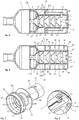
- the noise reduction device or silencer 1 illustrated on the Figures 1 to 3 is intended to be coupled to the muzzle 1A of a barrel of a firearm.
- the silencer 1 has a cylindrical general body of longitudinal axis X.
- the expansion chamber 11 is hollow and cylindrical; it receives the propulsion gases emitted during the firing.
- the central portion 2 In the axial continuity of the expansion chamber 11 is disposed the central portion 2 with the main pipe 21 through which is intended to pass the projectile and the main flow of gas.
- the baffles 20 constitute, in a known manner, decompression chambers which make it possible to slow down the gases of said main stream.
- the purpose of the distribution system 3 of the gas flow is to separate the gases from the expansion chamber 11 in several streams, on the one hand the main stream passing through the central part 2 (illustrated by the arrows F1 in the schematic figure 2 ), and secondly, at least one secondary flow traversing said sharing system 3, in particular two secondary flows in the embodiment illustrated in the figures (represented by the arrows F2 and F3 on the figure 2 ).
- the distribution system 3 comprises flow retarding means 4 whose role is to slow down the secondary flow or flows.
- the distribution system 3 comprises a hollow envelope 31 with a peripheral wall ( Figures 2 and 3 ), in which are housed the various components of said distribution system detailed below.
- the peripheral wall may be full.
- the wall 31 of the casing has one or more louvers 31 'of air intake from outside the device.
- the distribution system 3 comprises in the example shown two secondary chambers 3A and 3B ( Figures 5 and 6 ) separated and arranged around said central portion 2.
- the sharing system 3 is designed to generate two separate secondary flows which respectively run in the two semi-cylindrical secondary chambers 3A and 3B provided with flow-retarding means 4.
- the secondary flow could be unique by forming a cylindrical annular flow flowing in a cylindrical annular volume around the central portion 2.
- the distribution system 3 of the flow comprises, from upstream to downstream, a distribution ring 32 ( figures 3 and 7 ) provided with a plurality of orifices 32 ', a perforated upstream flange 33 which is provided with openings 33' whose number is advantageously less than the number of orifices 32 'of the crown, the secondary chambers 3A and 3B which communicate with the lights 33 'and in which are arranged the flow retarding means 4, and a downstream perforated flange 34 which is provided with output ports 34' which communicate with said secondary chambers 3A and 3B and open on the outside of the silencer.
- the distribution ring 32 is substantially frustoconical comprising an inclined wall 32 "converging towards the longitudinal axis X from the upstream to the downstream of the silencer It has its upstream distal end 32A intended to be integrated in the chamber of expansion 11 and its downstream end 32B integral with the body 30.
- the orifices 32 ' are distributed on the inclined periphery wall 32 "of the ring and open outwardly to the body 30 and facing the upstream flange 33.
- the number of orifices 32' is example between 5 and 10.
- the upstream flange 33 is annular and integral with the external face of the body 30. It is arranged at a distance and vis-à-vis the ring 32. In the example shown, the upstream flange 33 has two diametrically opposite slots 33 '. only one of which is visible on the figure 3 . The lights 33 'of the flange are offset relative to the axis of the orifices 32' of the ring 32.
- the orifices 32 'of the ring make it possible to capture a portion of the gases from the expansion chamber 11 in order to generate the secondary flows.
- the solid surface of the flange 33 combined with the reduced number of the lights 33 ' makes it possible to slow down the secondary flows emerging from the orifices 32' and then flowing between the volume defined by the ring gear 32 and the flange 33, and passing through said slots 33 'to penetrate in secondary rooms 3A and 3B.
- the secondary chambers 3A and 3B extend parallel to the central part 2 and thus to the baffles 20. They form two closed and distinct spaces in the manner of two partial shells in an arc of a circle, symmetrical with respect to the axis X, and delimited by the external surface of the body 30, the casing 31 and the upstream and downstream flanges 33 and 34.
- the secondary chambers 3A and 3B comprise the retarding means 4.
- the latter comprise partially spaced sequential partitions 40 to 42, the individual openings (access passage for the flow) of two adjacent partitions not facing each other.
- the retarding means 4 thus form an alternation of staggered baffles requiring the secondary flow of each chamber to circulate in a sinuous path allowing a slowdown of the flow of gas within each chamber.
- the downstream flange 34 is similar to the upstream flange and comprises two symmetrical lights 34 'through which escape the respective flows of the secondary chambers 3A and 3B. The limited number of preferably single light 34 'per chamber further slows the flow.
- an end piece 35 whose main surface arranged in a plane transverse to the X axis is perforated on the one hand at its center 35 'to allow the axial passage to the main flow escaping from the last baffle 20 of the central portion 2, and secondly at different locations on the circular periphery of the main surface, by example according to four exhaust holes 35 "from which the gases exit the secondary flows from the lights 34 '.
- the muffler further comprises exhaust means, such as closable vents 36 (here two symmetrical vents in the embodiment) which are arranged in the body 30 to communicate with the interior of the interior. the central portion 2 and the secondary chambers 3A and 3B.
- exhaust means such as closable vents 36 (here two symmetrical vents in the embodiment) which are arranged in the body 30 to communicate with the interior of the interior. the central portion 2 and the secondary chambers 3A and 3B.
- vents 36 are provided downstream of the secondary chambers 3A and 3B of the distribution system 3.
- Figures 5, 6 and 8 each vent 36 communicates with a secondary chamber for example tangentially to the outer peripheral surface of the body 30 between the last partition 42 and the downstream flange 34 via a passage 37.
- the exhaust of the gases from the main stream of the central part 2 towards the vents 36 is made for example via an annular ring 22 ( Figures 4 to 6 ) has a plurality of orifices 23 over its entire periphery.
- the gases escape through the orifices 23 and follow the periphery of the ring until meeting the vents 36 of the body 30 of the distribution system 3, the vents being arranged in the same transverse plane as that of the ring.
- the vents 36 are closed by movable closing means 5 which are used for their opening in response to a detected temperature rise.
- the closure means 5 are for example at least one bimetallic fixed at one of its ends to the distribution system 3 and provided at its opposite end with a needle 50 adapted to cooperate in the rest position with a vent 36 for 'seal.
- the deformation of the bimetal causes the displacement of the needle 50 and therefore the opening of the vent.
- the deformation is at a set temperature, for example of the order of a hundred degree.
- the invention is not limited to the exemplary embodiment illustrated, especially with regard to the number and arrangement of the constituent elements of the distribution system and slowing down.
- the invention relates to any device whose system of distribution / deviation and slowing of gas and enveloping the central part, generate from the expansion chamber at least one secondary flow distinct from the main flow through the central part of the device, the secondary flow providing a cladding of the main flow, and being furthermore advantageously slowed with respect to the main flow.
Landscapes
- Engineering & Computer Science (AREA)
- General Engineering & Computer Science (AREA)
- Exhaust Silencers (AREA)
- Fluidized-Bed Combustion And Resonant Combustion (AREA)
Applications Claiming Priority (1)
| Application Number | Priority Date | Filing Date | Title |
|---|---|---|---|
| FR1771252A FR3073938B1 (fr) | 2017-11-23 | 2017-11-23 | Dispositif reducteur de bruit pour arme a feu |
Publications (2)
| Publication Number | Publication Date |
|---|---|
| EP3489613A1 true EP3489613A1 (de) | 2019-05-29 |
| EP3489613B1 EP3489613B1 (de) | 2020-10-07 |
Family
ID=61913351
Family Applications (1)
| Application Number | Title | Priority Date | Filing Date |
|---|---|---|---|
| EP18207988.9A Active EP3489613B1 (de) | 2017-11-23 | 2018-11-23 | Geräuschdämpfungsvorrichtung für feuerwaffe |
Country Status (2)
| Country | Link |
|---|---|
| EP (1) | EP3489613B1 (de) |
| FR (1) | FR3073938B1 (de) |
Cited By (3)
| Publication number | Priority date | Publication date | Assignee | Title |
|---|---|---|---|---|
| US12044495B2 (en) | 2019-03-22 | 2024-07-23 | A-Tec Holding As | Coaxial gas flow silencer for a firearm |
| DE102024002317A1 (de) * | 2024-07-17 | 2026-01-22 | Apworks Gmbh | Schalldämpfer und verfahren zur herstellung eines schalldämpfers |
| EP4722632A1 (de) | 2024-10-07 | 2026-04-08 | B&T Ag | Schalldämpfer für eine feuerwaffe |
Families Citing this family (1)
| Publication number | Priority date | Publication date | Assignee | Title |
|---|---|---|---|---|
| RU2751835C1 (ru) * | 2021-01-12 | 2021-07-19 | Борис Александрович Крестинин | Дульное устройство для огнестрельного оружия |
Citations (4)
| Publication number | Priority date | Publication date | Assignee | Title |
|---|---|---|---|---|
| US1860276A (en) * | 1929-07-10 | 1932-05-24 | It Miglioramento Armi Soc | Firearm |
| US2351037A (en) * | 1936-10-16 | 1944-06-13 | Samuel G Green | Stabilizer for guns |
| FR2407451A1 (fr) * | 1977-10-25 | 1979-05-25 | Bensa Jacques | Moderateur de son pour carabines et fusils |
| EP2653821A1 (de) * | 2012-04-18 | 2013-10-23 | Christophe Maraux | Schalldämpfer für eine Waffe |
-
2017
- 2017-11-23 FR FR1771252A patent/FR3073938B1/fr active Active
-
2018
- 2018-11-23 EP EP18207988.9A patent/EP3489613B1/de active Active
Patent Citations (4)
| Publication number | Priority date | Publication date | Assignee | Title |
|---|---|---|---|---|
| US1860276A (en) * | 1929-07-10 | 1932-05-24 | It Miglioramento Armi Soc | Firearm |
| US2351037A (en) * | 1936-10-16 | 1944-06-13 | Samuel G Green | Stabilizer for guns |
| FR2407451A1 (fr) * | 1977-10-25 | 1979-05-25 | Bensa Jacques | Moderateur de son pour carabines et fusils |
| EP2653821A1 (de) * | 2012-04-18 | 2013-10-23 | Christophe Maraux | Schalldämpfer für eine Waffe |
Cited By (3)
| Publication number | Priority date | Publication date | Assignee | Title |
|---|---|---|---|---|
| US12044495B2 (en) | 2019-03-22 | 2024-07-23 | A-Tec Holding As | Coaxial gas flow silencer for a firearm |
| DE102024002317A1 (de) * | 2024-07-17 | 2026-01-22 | Apworks Gmbh | Schalldämpfer und verfahren zur herstellung eines schalldämpfers |
| EP4722632A1 (de) | 2024-10-07 | 2026-04-08 | B&T Ag | Schalldämpfer für eine feuerwaffe |
Also Published As
| Publication number | Publication date |
|---|---|
| EP3489613B1 (de) | 2020-10-07 |
| FR3073938B1 (fr) | 2021-01-08 |
| FR3073938A1 (fr) | 2019-05-24 |
Similar Documents
| Publication | Publication Date | Title |
|---|---|---|
| EP3489613B1 (de) | Geräuschdämpfungsvorrichtung für feuerwaffe | |
| US7870815B2 (en) | Gun flash hider | |
| US9933224B2 (en) | Modular gun silencer | |
| US9316456B1 (en) | Firearm discharge gas flow control modules and associated methods | |
| US9879933B2 (en) | Barrel nut mounted integral firearm sound suppressor | |
| US10113826B2 (en) | Firearm suppressor | |
| US10126083B2 (en) | Firearm suppressor and method of operation | |
| US10634444B2 (en) | Method and apparatus for parallel path firearm sound suppression | |
| US20200025494A1 (en) | Suppressor with Coaxial Expansion Chambers and Tapered Seals | |
| JP2019536979A (ja) | サウンドサプレッサ | |
| US12018906B2 (en) | Firearm suppression system | |
| EP0772758A1 (de) | Schalldämpfer für gewehre | |
| EP2653821B1 (de) | Schalldämpfer für eine Waffe | |
| US11740042B2 (en) | Gas tube supports for post barrel plenum operated gas cycling system for automatic firearms | |
| RU2402736C1 (ru) | Комплект интегрированного глушителя и заглушки - дульного тормоза-компенсатора для дозвукового и сверхзвукового режимов стрельбы из огнестрельного оружия | |
| EP0151112A1 (de) | Waffenstabilisator und -rückstossverminderer | |
| RU2164334C1 (ru) | Механизм регулировки давления газов автоматического оружия | |
| RU2494333C1 (ru) | Быстросъемный глушитель | |
| US3008378A (en) | Powder grain baffle for recoilless rifle | |
| RU2828912C1 (ru) | Прибор малошумной стрельбы для стрелкового оружия | |
| FR2677743A1 (fr) | Attenuateur de bruit pour fusil de chasse ou de tir sportif. | |
| RU2833494C1 (ru) | Ствольный пулевой ускоритель-тормоз-глушитель | |
| WO2025257802A1 (fr) | Dispositif modérateur de son pour arme à feu et arme à feu comportant un tel dispositif | |
| US12460888B1 (en) | Suppressor with gas cross flow and reduced back pressure | |
| RU2822683C1 (ru) | Дульный тормоз компенсатор-пламегаситель закрытого типа с системой газоразгрузки |
Legal Events
| Date | Code | Title | Description |
|---|---|---|---|
| PUAI | Public reference made under article 153(3) epc to a published international application that has entered the european phase |
Free format text: ORIGINAL CODE: 0009012 |
|
| STAA | Information on the status of an ep patent application or granted ep patent |
Free format text: STATUS: THE APPLICATION HAS BEEN PUBLISHED |
|
| AK | Designated contracting states |
Kind code of ref document: A1 Designated state(s): AL AT BE BG CH CY CZ DE DK EE ES FI FR GB GR HR HU IE IS IT LI LT LU LV MC MK MT NL NO PL PT RO RS SE SI SK SM TR |
|
| AX | Request for extension of the european patent |
Extension state: BA ME |
|
| STAA | Information on the status of an ep patent application or granted ep patent |
Free format text: STATUS: REQUEST FOR EXAMINATION WAS MADE |
|
| 17P | Request for examination filed |
Effective date: 20191126 |
|
| RBV | Designated contracting states (corrected) |
Designated state(s): AL AT BE BG CH CY CZ DE DK EE ES FI FR GB GR HR HU IE IS IT LI LT LU LV MC MK MT NL NO PL PT RO RS SE SI SK SM TR |
|
| GRAP | Despatch of communication of intention to grant a patent |
Free format text: ORIGINAL CODE: EPIDOSNIGR1 |
|
| STAA | Information on the status of an ep patent application or granted ep patent |
Free format text: STATUS: GRANT OF PATENT IS INTENDED |
|
| INTG | Intention to grant announced |
Effective date: 20200506 |
|
| GRAS | Grant fee paid |
Free format text: ORIGINAL CODE: EPIDOSNIGR3 |
|
| GRAA | (expected) grant |
Free format text: ORIGINAL CODE: 0009210 |
|
| STAA | Information on the status of an ep patent application or granted ep patent |
Free format text: STATUS: THE PATENT HAS BEEN GRANTED |
|
| AK | Designated contracting states |
Kind code of ref document: B1 Designated state(s): AL AT BE BG CH CY CZ DE DK EE ES FI FR GB GR HR HU IE IS IT LI LT LU LV MC MK MT NL NO PL PT RO RS SE SI SK SM TR |
|
| REG | Reference to a national code |
Ref country code: GB Ref legal event code: FG4D Free format text: NOT ENGLISH |
|
| REG | Reference to a national code |
Ref country code: CH Ref legal event code: EP Ref country code: AT Ref legal event code: REF Ref document number: 1321610 Country of ref document: AT Kind code of ref document: T Effective date: 20201015 |
|
| REG | Reference to a national code |
Ref country code: IE Ref legal event code: FG4D Free format text: LANGUAGE OF EP DOCUMENT: FRENCH |
|
| REG | Reference to a national code |
Ref country code: DE Ref legal event code: R096 Ref document number: 602018008490 Country of ref document: DE |
|
| REG | Reference to a national code |
Ref country code: FI Ref legal event code: FGE |
|
| REG | Reference to a national code |
Ref country code: CH Ref legal event code: NV Representative=s name: NOVAGRAAF INTERNATIONAL SA, CH |
|
| REG | Reference to a national code |
Ref country code: NO Ref legal event code: T2 Effective date: 20201007 |
|
| REG | Reference to a national code |
Ref country code: NL Ref legal event code: MP Effective date: 20201007 |
|
| REG | Reference to a national code |
Ref country code: AT Ref legal event code: MK05 Ref document number: 1321610 Country of ref document: AT Kind code of ref document: T Effective date: 20201007 |
|
| PG25 | Lapsed in a contracting state [announced via postgrant information from national office to epo] |
Ref country code: GR Free format text: LAPSE BECAUSE OF FAILURE TO SUBMIT A TRANSLATION OF THE DESCRIPTION OR TO PAY THE FEE WITHIN THE PRESCRIBED TIME-LIMIT Effective date: 20210108 Ref country code: RS Free format text: LAPSE BECAUSE OF FAILURE TO SUBMIT A TRANSLATION OF THE DESCRIPTION OR TO PAY THE FEE WITHIN THE PRESCRIBED TIME-LIMIT Effective date: 20201007 Ref country code: PT Free format text: LAPSE BECAUSE OF FAILURE TO SUBMIT A TRANSLATION OF THE DESCRIPTION OR TO PAY THE FEE WITHIN THE PRESCRIBED TIME-LIMIT Effective date: 20210208 |
|
| REG | Reference to a national code |
Ref country code: LT Ref legal event code: MG4D |
|
| PG25 | Lapsed in a contracting state [announced via postgrant information from national office to epo] |
Ref country code: SE Free format text: LAPSE BECAUSE OF FAILURE TO SUBMIT A TRANSLATION OF THE DESCRIPTION OR TO PAY THE FEE WITHIN THE PRESCRIBED TIME-LIMIT Effective date: 20201007 Ref country code: LV Free format text: LAPSE BECAUSE OF FAILURE TO SUBMIT A TRANSLATION OF THE DESCRIPTION OR TO PAY THE FEE WITHIN THE PRESCRIBED TIME-LIMIT Effective date: 20201007 Ref country code: IS Free format text: LAPSE BECAUSE OF FAILURE TO SUBMIT A TRANSLATION OF THE DESCRIPTION OR TO PAY THE FEE WITHIN THE PRESCRIBED TIME-LIMIT Effective date: 20210207 Ref country code: PL Free format text: LAPSE BECAUSE OF FAILURE TO SUBMIT A TRANSLATION OF THE DESCRIPTION OR TO PAY THE FEE WITHIN THE PRESCRIBED TIME-LIMIT Effective date: 20201007 Ref country code: BG Free format text: LAPSE BECAUSE OF FAILURE TO SUBMIT A TRANSLATION OF THE DESCRIPTION OR TO PAY THE FEE WITHIN THE PRESCRIBED TIME-LIMIT Effective date: 20210107 Ref country code: AT Free format text: LAPSE BECAUSE OF FAILURE TO SUBMIT A TRANSLATION OF THE DESCRIPTION OR TO PAY THE FEE WITHIN THE PRESCRIBED TIME-LIMIT Effective date: 20201007 Ref country code: ES Free format text: LAPSE BECAUSE OF FAILURE TO SUBMIT A TRANSLATION OF THE DESCRIPTION OR TO PAY THE FEE WITHIN THE PRESCRIBED TIME-LIMIT Effective date: 20201007 |
|
| PG25 | Lapsed in a contracting state [announced via postgrant information from national office to epo] |
Ref country code: NL Free format text: LAPSE BECAUSE OF FAILURE TO SUBMIT A TRANSLATION OF THE DESCRIPTION OR TO PAY THE FEE WITHIN THE PRESCRIBED TIME-LIMIT Effective date: 20201007 Ref country code: HR Free format text: LAPSE BECAUSE OF FAILURE TO SUBMIT A TRANSLATION OF THE DESCRIPTION OR TO PAY THE FEE WITHIN THE PRESCRIBED TIME-LIMIT Effective date: 20201007 |
|
| REG | Reference to a national code |
Ref country code: DE Ref legal event code: R097 Ref document number: 602018008490 Country of ref document: DE |
|
| PG25 | Lapsed in a contracting state [announced via postgrant information from national office to epo] |
Ref country code: SK Free format text: LAPSE BECAUSE OF FAILURE TO SUBMIT A TRANSLATION OF THE DESCRIPTION OR TO PAY THE FEE WITHIN THE PRESCRIBED TIME-LIMIT Effective date: 20201007 Ref country code: SM Free format text: LAPSE BECAUSE OF FAILURE TO SUBMIT A TRANSLATION OF THE DESCRIPTION OR TO PAY THE FEE WITHIN THE PRESCRIBED TIME-LIMIT Effective date: 20201007 Ref country code: CZ Free format text: LAPSE BECAUSE OF FAILURE TO SUBMIT A TRANSLATION OF THE DESCRIPTION OR TO PAY THE FEE WITHIN THE PRESCRIBED TIME-LIMIT Effective date: 20201007 Ref country code: EE Free format text: LAPSE BECAUSE OF FAILURE TO SUBMIT A TRANSLATION OF THE DESCRIPTION OR TO PAY THE FEE WITHIN THE PRESCRIBED TIME-LIMIT Effective date: 20201007 Ref country code: LU Free format text: LAPSE BECAUSE OF NON-PAYMENT OF DUE FEES Effective date: 20201123 Ref country code: LT Free format text: LAPSE BECAUSE OF FAILURE TO SUBMIT A TRANSLATION OF THE DESCRIPTION OR TO PAY THE FEE WITHIN THE PRESCRIBED TIME-LIMIT Effective date: 20201007 Ref country code: MC Free format text: LAPSE BECAUSE OF FAILURE TO SUBMIT A TRANSLATION OF THE DESCRIPTION OR TO PAY THE FEE WITHIN THE PRESCRIBED TIME-LIMIT Effective date: 20201007 Ref country code: RO Free format text: LAPSE BECAUSE OF FAILURE TO SUBMIT A TRANSLATION OF THE DESCRIPTION OR TO PAY THE FEE WITHIN THE PRESCRIBED TIME-LIMIT Effective date: 20201007 |
|
| PLBE | No opposition filed within time limit |
Free format text: ORIGINAL CODE: 0009261 |
|
| STAA | Information on the status of an ep patent application or granted ep patent |
Free format text: STATUS: NO OPPOSITION FILED WITHIN TIME LIMIT |
|
| PG25 | Lapsed in a contracting state [announced via postgrant information from national office to epo] |
Ref country code: DK Free format text: LAPSE BECAUSE OF FAILURE TO SUBMIT A TRANSLATION OF THE DESCRIPTION OR TO PAY THE FEE WITHIN THE PRESCRIBED TIME-LIMIT Effective date: 20201007 |
|
| 26N | No opposition filed |
Effective date: 20210708 |
|
| PG25 | Lapsed in a contracting state [announced via postgrant information from national office to epo] |
Ref country code: AL Free format text: LAPSE BECAUSE OF FAILURE TO SUBMIT A TRANSLATION OF THE DESCRIPTION OR TO PAY THE FEE WITHIN THE PRESCRIBED TIME-LIMIT Effective date: 20201007 Ref country code: IE Free format text: LAPSE BECAUSE OF NON-PAYMENT OF DUE FEES Effective date: 20201123 Ref country code: IT Free format text: LAPSE BECAUSE OF FAILURE TO SUBMIT A TRANSLATION OF THE DESCRIPTION OR TO PAY THE FEE WITHIN THE PRESCRIBED TIME-LIMIT Effective date: 20201007 |
|
| PG25 | Lapsed in a contracting state [announced via postgrant information from national office to epo] |
Ref country code: SI Free format text: LAPSE BECAUSE OF FAILURE TO SUBMIT A TRANSLATION OF THE DESCRIPTION OR TO PAY THE FEE WITHIN THE PRESCRIBED TIME-LIMIT Effective date: 20201007 |
|
| REG | Reference to a national code |
Ref country code: FI Ref legal event code: PCE Owner name: B&T AG |
|
| REG | Reference to a national code |
Ref country code: DE Ref legal event code: R081 Ref document number: 602018008490 Country of ref document: DE Owner name: B&T AG, CH Free format text: FORMER OWNER: DELTAFLUID, LACQ, FR |
|
| REG | Reference to a national code |
Ref country code: NO Ref legal event code: CHAD Owner name: B&T AG, CH |
|
| REG | Reference to a national code |
Ref country code: BE Ref legal event code: PD Owner name: B&T AG; CH Free format text: DETAILS ASSIGNMENT: CHANGE OF OWNER(S), ASSIGNMENT; FORMER OWNER NAME: DELTAFLUID Effective date: 20220105 |
|
| PG25 | Lapsed in a contracting state [announced via postgrant information from national office to epo] |
Ref country code: IS Free format text: LAPSE BECAUSE OF FAILURE TO SUBMIT A TRANSLATION OF THE DESCRIPTION OR TO PAY THE FEE WITHIN THE PRESCRIBED TIME-LIMIT Effective date: 20210207 Ref country code: TR Free format text: LAPSE BECAUSE OF FAILURE TO SUBMIT A TRANSLATION OF THE DESCRIPTION OR TO PAY THE FEE WITHIN THE PRESCRIBED TIME-LIMIT Effective date: 20201007 Ref country code: MT Free format text: LAPSE BECAUSE OF FAILURE TO SUBMIT A TRANSLATION OF THE DESCRIPTION OR TO PAY THE FEE WITHIN THE PRESCRIBED TIME-LIMIT Effective date: 20201007 Ref country code: CY Free format text: LAPSE BECAUSE OF FAILURE TO SUBMIT A TRANSLATION OF THE DESCRIPTION OR TO PAY THE FEE WITHIN THE PRESCRIBED TIME-LIMIT Effective date: 20201007 |
|
| PG25 | Lapsed in a contracting state [announced via postgrant information from national office to epo] |
Ref country code: MK Free format text: LAPSE BECAUSE OF FAILURE TO SUBMIT A TRANSLATION OF THE DESCRIPTION OR TO PAY THE FEE WITHIN THE PRESCRIBED TIME-LIMIT Effective date: 20201007 |
|
| GBPC | Gb: european patent ceased through non-payment of renewal fee |
Effective date: 20221123 |
|
| PG25 | Lapsed in a contracting state [announced via postgrant information from national office to epo] |
Ref country code: GB Free format text: LAPSE BECAUSE OF NON-PAYMENT OF DUE FEES Effective date: 20221123 |
|
| REG | Reference to a national code |
Ref country code: CH Ref legal event code: U11 Free format text: ST27 STATUS EVENT CODE: U-0-0-U10-U11 (AS PROVIDED BY THE NATIONAL OFFICE) Effective date: 20251201 |
|
| PGFP | Annual fee paid to national office [announced via postgrant information from national office to epo] |
Ref country code: DE Payment date: 20251128 Year of fee payment: 8 |
|
| PGFP | Annual fee paid to national office [announced via postgrant information from national office to epo] |
Ref country code: NO Payment date: 20251128 Year of fee payment: 8 |
|
| PGFP | Annual fee paid to national office [announced via postgrant information from national office to epo] |
Ref country code: FI Payment date: 20251125 Year of fee payment: 8 |
|
| PGFP | Annual fee paid to national office [announced via postgrant information from national office to epo] |
Ref country code: FR Payment date: 20251125 Year of fee payment: 8 |
|
| PGFP | Annual fee paid to national office [announced via postgrant information from national office to epo] |
Ref country code: BE Payment date: 20251127 Year of fee payment: 8 |
|
| PGFP | Annual fee paid to national office [announced via postgrant information from national office to epo] |
Ref country code: CH Payment date: 20251201 Year of fee payment: 8 |