EP3489576B1 - Light module for lighting and/or signalling of a motor vehicle - Google Patents
Light module for lighting and/or signalling of a motor vehicle Download PDFInfo
- Publication number
- EP3489576B1 EP3489576B1 EP18208370.9A EP18208370A EP3489576B1 EP 3489576 B1 EP3489576 B1 EP 3489576B1 EP 18208370 A EP18208370 A EP 18208370A EP 3489576 B1 EP3489576 B1 EP 3489576B1
- Authority
- EP
- European Patent Office
- Prior art keywords
- face
- optical device
- primary optical
- lighting module
- light
- Prior art date
- Legal status (The legal status is an assumption and is not a legal conclusion. Google has not performed a legal analysis and makes no representation as to the accuracy of the status listed.)
- Active
Links
- 230000011664 signaling Effects 0.000 title claims description 5
- 230000003287 optical effect Effects 0.000 claims description 112
- 238000005286 illumination Methods 0.000 claims 1
- 238000007493 shaping process Methods 0.000 description 19
- 230000000295 complement effect Effects 0.000 description 12
- 230000015572 biosynthetic process Effects 0.000 description 5
- 238000005520 cutting process Methods 0.000 description 4
- 210000000056 organ Anatomy 0.000 description 4
- 238000012423 maintenance Methods 0.000 description 3
- 239000004020 conductor Substances 0.000 description 2
- 230000007547 defect Effects 0.000 description 2
- 239000011521 glass Substances 0.000 description 2
- 238000004519 manufacturing process Methods 0.000 description 2
- 230000000873 masking effect Effects 0.000 description 2
- 239000000463 material Substances 0.000 description 2
- 238000003825 pressing Methods 0.000 description 2
- 230000002441 reversible effect Effects 0.000 description 2
- 238000000926 separation method Methods 0.000 description 2
- YMHOBZXQZVXHBM-UHFFFAOYSA-N 2,5-dimethoxy-4-bromophenethylamine Chemical compound COC1=CC(CCN)=C(OC)C=C1Br YMHOBZXQZVXHBM-UHFFFAOYSA-N 0.000 description 1
- 208000031968 Cadaver Diseases 0.000 description 1
- 241000545067 Venus Species 0.000 description 1
- 239000000853 adhesive Substances 0.000 description 1
- 230000001070 adhesive effect Effects 0.000 description 1
- 230000000903 blocking effect Effects 0.000 description 1
- 210000004027 cell Anatomy 0.000 description 1
- 239000011248 coating agent Substances 0.000 description 1
- 238000000576 coating method Methods 0.000 description 1
- 239000003086 colorant Substances 0.000 description 1
- 238000002788 crimping Methods 0.000 description 1
- 230000006866 deterioration Effects 0.000 description 1
- 238000006073 displacement reaction Methods 0.000 description 1
- 230000004313 glare Effects 0.000 description 1
- 239000003292 glue Substances 0.000 description 1
- 238000003780 insertion Methods 0.000 description 1
- 230000037431 insertion Effects 0.000 description 1
- 230000007774 longterm Effects 0.000 description 1
- 239000002184 metal Substances 0.000 description 1
- 230000002093 peripheral effect Effects 0.000 description 1
- 230000001105 regulatory effect Effects 0.000 description 1
- 229920002994 synthetic fiber Polymers 0.000 description 1
Images


Classifications
-
- F—MECHANICAL ENGINEERING; LIGHTING; HEATING; WEAPONS; BLASTING
- F21—LIGHTING
- F21S—NON-PORTABLE LIGHTING DEVICES; SYSTEMS THEREOF; VEHICLE LIGHTING DEVICES SPECIALLY ADAPTED FOR VEHICLE EXTERIORS
- F21S41/00—Illuminating devices specially adapted for vehicle exteriors, e.g. headlamps
- F21S41/20—Illuminating devices specially adapted for vehicle exteriors, e.g. headlamps characterised by refractors, transparent cover plates, light guides or filters
- F21S41/29—Attachment thereof
-
- F—MECHANICAL ENGINEERING; LIGHTING; HEATING; WEAPONS; BLASTING
- F21—LIGHTING
- F21S—NON-PORTABLE LIGHTING DEVICES; SYSTEMS THEREOF; VEHICLE LIGHTING DEVICES SPECIALLY ADAPTED FOR VEHICLE EXTERIORS
- F21S41/00—Illuminating devices specially adapted for vehicle exteriors, e.g. headlamps
- F21S41/10—Illuminating devices specially adapted for vehicle exteriors, e.g. headlamps characterised by the light source
- F21S41/14—Illuminating devices specially adapted for vehicle exteriors, e.g. headlamps characterised by the light source characterised by the type of light source
- F21S41/141—Light emitting diodes [LED]
- F21S41/143—Light emitting diodes [LED] the main emission direction of the LED being parallel to the optical axis of the illuminating device
-
- F—MECHANICAL ENGINEERING; LIGHTING; HEATING; WEAPONS; BLASTING
- F21—LIGHTING
- F21S—NON-PORTABLE LIGHTING DEVICES; SYSTEMS THEREOF; VEHICLE LIGHTING DEVICES SPECIALLY ADAPTED FOR VEHICLE EXTERIORS
- F21S41/00—Illuminating devices specially adapted for vehicle exteriors, e.g. headlamps
- F21S41/10—Illuminating devices specially adapted for vehicle exteriors, e.g. headlamps characterised by the light source
- F21S41/14—Illuminating devices specially adapted for vehicle exteriors, e.g. headlamps characterised by the light source characterised by the type of light source
- F21S41/141—Light emitting diodes [LED]
- F21S41/151—Light emitting diodes [LED] arranged in one or more lines
- F21S41/153—Light emitting diodes [LED] arranged in one or more lines arranged in a matrix
-
- F—MECHANICAL ENGINEERING; LIGHTING; HEATING; WEAPONS; BLASTING
- F21—LIGHTING
- F21S—NON-PORTABLE LIGHTING DEVICES; SYSTEMS THEREOF; VEHICLE LIGHTING DEVICES SPECIALLY ADAPTED FOR VEHICLE EXTERIORS
- F21S41/00—Illuminating devices specially adapted for vehicle exteriors, e.g. headlamps
- F21S41/10—Illuminating devices specially adapted for vehicle exteriors, e.g. headlamps characterised by the light source
- F21S41/19—Attachment of light sources or lamp holders
- F21S41/192—Details of lamp holders, terminals or connectors
-
- F—MECHANICAL ENGINEERING; LIGHTING; HEATING; WEAPONS; BLASTING
- F21—LIGHTING
- F21S—NON-PORTABLE LIGHTING DEVICES; SYSTEMS THEREOF; VEHICLE LIGHTING DEVICES SPECIALLY ADAPTED FOR VEHICLE EXTERIORS
- F21S41/00—Illuminating devices specially adapted for vehicle exteriors, e.g. headlamps
- F21S41/20—Illuminating devices specially adapted for vehicle exteriors, e.g. headlamps characterised by refractors, transparent cover plates, light guides or filters
- F21S41/24—Light guides
-
- F—MECHANICAL ENGINEERING; LIGHTING; HEATING; WEAPONS; BLASTING
- F21—LIGHTING
- F21S—NON-PORTABLE LIGHTING DEVICES; SYSTEMS THEREOF; VEHICLE LIGHTING DEVICES SPECIALLY ADAPTED FOR VEHICLE EXTERIORS
- F21S41/00—Illuminating devices specially adapted for vehicle exteriors, e.g. headlamps
- F21S41/30—Illuminating devices specially adapted for vehicle exteriors, e.g. headlamps characterised by reflectors
- F21S41/32—Optical layout thereof
- F21S41/322—Optical layout thereof the reflector using total internal reflection
-
- F—MECHANICAL ENGINEERING; LIGHTING; HEATING; WEAPONS; BLASTING
- F21—LIGHTING
- F21S—NON-PORTABLE LIGHTING DEVICES; SYSTEMS THEREOF; VEHICLE LIGHTING DEVICES SPECIALLY ADAPTED FOR VEHICLE EXTERIORS
- F21S41/00—Illuminating devices specially adapted for vehicle exteriors, e.g. headlamps
- F21S41/40—Illuminating devices specially adapted for vehicle exteriors, e.g. headlamps characterised by screens, non-reflecting members, light-shielding members or fixed shades
- F21S41/43—Illuminating devices specially adapted for vehicle exteriors, e.g. headlamps characterised by screens, non-reflecting members, light-shielding members or fixed shades characterised by the shape thereof
-
- F—MECHANICAL ENGINEERING; LIGHTING; HEATING; WEAPONS; BLASTING
- F21—LIGHTING
- F21S—NON-PORTABLE LIGHTING DEVICES; SYSTEMS THEREOF; VEHICLE LIGHTING DEVICES SPECIALLY ADAPTED FOR VEHICLE EXTERIORS
- F21S41/00—Illuminating devices specially adapted for vehicle exteriors, e.g. headlamps
- F21S41/40—Illuminating devices specially adapted for vehicle exteriors, e.g. headlamps characterised by screens, non-reflecting members, light-shielding members or fixed shades
- F21S41/47—Attachment thereof
-
- F—MECHANICAL ENGINEERING; LIGHTING; HEATING; WEAPONS; BLASTING
- F21—LIGHTING
- F21S—NON-PORTABLE LIGHTING DEVICES; SYSTEMS THEREOF; VEHICLE LIGHTING DEVICES SPECIALLY ADAPTED FOR VEHICLE EXTERIORS
- F21S41/00—Illuminating devices specially adapted for vehicle exteriors, e.g. headlamps
- F21S41/60—Illuminating devices specially adapted for vehicle exteriors, e.g. headlamps characterised by a variable light distribution
- F21S41/65—Illuminating devices specially adapted for vehicle exteriors, e.g. headlamps characterised by a variable light distribution by acting on light sources
- F21S41/663—Illuminating devices specially adapted for vehicle exteriors, e.g. headlamps characterised by a variable light distribution by acting on light sources by switching light sources
-
- F—MECHANICAL ENGINEERING; LIGHTING; HEATING; WEAPONS; BLASTING
- F21—LIGHTING
- F21S—NON-PORTABLE LIGHTING DEVICES; SYSTEMS THEREOF; VEHICLE LIGHTING DEVICES SPECIALLY ADAPTED FOR VEHICLE EXTERIORS
- F21S43/00—Signalling devices specially adapted for vehicle exteriors, e.g. brake lamps, direction indicator lights or reversing lights
- F21S43/10—Signalling devices specially adapted for vehicle exteriors, e.g. brake lamps, direction indicator lights or reversing lights characterised by the light source
- F21S43/19—Attachment of light sources or lamp holders
- F21S43/195—Details of lamp holders, terminals or connectors
-
- F—MECHANICAL ENGINEERING; LIGHTING; HEATING; WEAPONS; BLASTING
- F21—LIGHTING
- F21S—NON-PORTABLE LIGHTING DEVICES; SYSTEMS THEREOF; VEHICLE LIGHTING DEVICES SPECIALLY ADAPTED FOR VEHICLE EXTERIORS
- F21S45/00—Arrangements within vehicle lighting devices specially adapted for vehicle exteriors, for purposes other than emission or distribution of light
- F21S45/10—Protection of lighting devices
-
- F—MECHANICAL ENGINEERING; LIGHTING; HEATING; WEAPONS; BLASTING
- F21—LIGHTING
- F21S—NON-PORTABLE LIGHTING DEVICES; SYSTEMS THEREOF; VEHICLE LIGHTING DEVICES SPECIALLY ADAPTED FOR VEHICLE EXTERIORS
- F21S41/00—Illuminating devices specially adapted for vehicle exteriors, e.g. headlamps
- F21S41/30—Illuminating devices specially adapted for vehicle exteriors, e.g. headlamps characterised by reflectors
- F21S41/32—Optical layout thereof
- F21S41/36—Combinations of two or more separate reflectors
- F21S41/365—Combinations of two or more separate reflectors successively reflecting the light
-
- F—MECHANICAL ENGINEERING; LIGHTING; HEATING; WEAPONS; BLASTING
- F21—LIGHTING
- F21W—INDEXING SCHEME ASSOCIATED WITH SUBCLASSES F21K, F21L, F21S and F21V, RELATING TO USES OR APPLICATIONS OF LIGHTING DEVICES OR SYSTEMS
- F21W2102/00—Exterior vehicle lighting devices for illuminating purposes
-
- F—MECHANICAL ENGINEERING; LIGHTING; HEATING; WEAPONS; BLASTING
- F21—LIGHTING
- F21W—INDEXING SCHEME ASSOCIATED WITH SUBCLASSES F21K, F21L, F21S and F21V, RELATING TO USES OR APPLICATIONS OF LIGHTING DEVICES OR SYSTEMS
- F21W2103/00—Exterior vehicle lighting devices for signalling purposes
Definitions
- the present invention relates to the field of light modules used for the lighting and/or signaling of motor vehicles (see for example the document US 2009/016074 A ), and it applies more particularly to light modules comprising optical devices for forming different light beams, and in particular a so-called passing beam and a so-called driving beam.
- Automotive headlamps usually consist of a housing which is closed by a transparent wall through which one or more light beams pass.
- This box houses at least one light module, mainly comprising a light source and an optical system configured to conform the light generated by the light source in order to provide specific lighting and/or signaling services for the vehicle.
- the optical system can be configured to allow the projection at the output of the headlight of a so-called dipped light beam, in order in particular to limit glare for the drivers of vehicles traveling in the opposite direction.
- the light module comprises at least one light source, a primary optical device positioned opposite the light source to guide the light rays, a cover element that can form a cutting of the light rays emitted in order to form a partial light beam capable of not dazzling third parties at the output of the headlamp, and a lens for shaping these rays to form the light beam at the output of the headlamp.
- the masking element is arranged on the path of the rays, at a distance from the light source and that it is necessary to ensure the position of the latter in the long term so that the shape given to the rays for the so-called crossing light beam is stable over time.
- additional light modules can be associated in the same headlamp to perform a main beam function, capable of illuminating a road scene with a long range, when the risk of dazzling third parties is not present.
- These additional light modules again comprise one or more light sources and a primary optical device associated with a shaping lens for the projection of the rays.
- light modules are provided in which these two functions are performed, the light sources and the primary optical devices having to be arranged relative to each other to perform these different functions according to the switching on of one and /or the other of the light sources.
- First light sources are switched on when it is appropriate to emit a first beam of the dipped beam type, and second light sources are switched on in addition to emit a beam complementary to this first beam to form, by combining the two beams, a beam of high beam type.
- Such arrangements may involve the placement of primary optical devices, and/or of a masking element, which have a distal end face at a distance from a base forming a support for the light sources. It is understood that the manufacturing clearances of these primary optical devices, produced in series, can generate a positioning error. A manufacturing defect at the base of the primary optical device, and in particular at the place where the base will be fixed to the support, can lead to poor positioning of the device, especially since the overhang is tall. Moreover, it appeared that the mechanical vibrations and the temperature variations to which the light module is exposed during its use can cause over time a variation in the more or less pronounced inclination of these primary optical devices with respect to the light source.
- This inclination has the disadvantage of modifying the area illuminated by the dipped headlights, which can prove to be unpleasant or even dangerous for the drivers of vehicles traveling in reverse. It is then necessary to carry out regular maintenance of the light module in order to correct this defect to prevent any accident.
- the invention proposes to produce a light module comprising a primary optical device whose position is less likely to vary over time with respect to the light source of the light module.
- the subject of the invention is a light module for the lighting and/or signaling of a motor vehicle according to claim 1.
- the terms “receiving part” and “output face” are understood to mean respectively the part of the primary optical device illuminated by the light source and the face of the primary optical device through which this light is emitted in the direction of a shaping lens.
- the light module according to the invention comprises at least one arm projecting from the first face of the base and holding the primary optical device at the level of a holding zone located between the receiving part and the exit face of the primary optical device. In this way, it is possible to limit or prevent the inclination of the primary optical device with respect to the base and to ensure a reliable position of the primary optical device in the light module.
- the invention also covers a motor vehicle headlamp comprising at least one light module as described in this document, in its most limited form or comprising one or more of the characteristics set out above.
- longitudinal or lateral above, below, in front, behind refer to the orientation of the light module 2 as it is intended to be integrated into a motor vehicle headlight.
- a longitudinal direction corresponds to an optical axis A along which the light rays generated by the light module 2 mainly extend.
- the lateral orientation corresponds to a straight line perpendicular to the optical axis A and which extends horizontally.
- the vertical direction corresponds to an orientation perpendicular to the optical axis A and to the lateral orientation.
- the figure 1 illustrates a light module 2 according to the invention, otherwise called an optical module, whose function is to generate and project one or more light beams onto a road.
- a light module 2 is intended to be installed in a headlamp of a motor vehicle not shown in the figures in order to facilitate understanding of the invention.
- the headlamp mentioned here generally comprises a rear casing closed at the front by a transparent glass, the latter being traversed by the light rays created by the light module according to the invention.
- Such a projector can thus receive in its interior volume, delimited by the rear casing and the transparent glass, a plurality of light modules, and at least one light module according to the invention.
- Such a light module 2 forms a unitary sub-assembly, that is to say an object which can fulfill its function without any other input than the electrical energy necessary for its ignition, and if necessary with the aid of a electric current regulation module to protect the module from excessive temperatures.
- the light module 2 is arranged to create a low beam beam and a high beam beam.
- the light module 2 is adapted so that the main beam is the combination of the dipped beam with a complementary beam which illuminates above and/or below the dipped beam, the assembly thus forming the main beam.
- the light module 2 comprises at least one light source 4 in particular visible on the figure 2 . It also comprises at least one lens 6 arranged at one end of the module so as to be traversed by the light rays emitted by the light source 4. Such a shaping lens 6 contributes to the formation of the desired light beam, which this is a low beam type beam or a high beam type beam. In other words, the shaping lens 6 forms a first longitudinal end of the light module 2.
- the figure 1 also shows the presence of a support 8 of shaping lens 6 which has a substantially tubular shape and which extends between a base 10 and the shaping lens 6.
- the lens can be snapped directly onto the support, or else be fixed by means of a fixing ring 11 pressing the shaping lens 6 against a longitudinal end of the support 8.
- This support 8 also provides mechanical referencing of the position of the shaping lens 6 relative to the light source 4, via the base 10, so as to guarantee a determined position of the shaping lens 6 relative to the light source 4.
- the support 8 is in particular formed by two longitudinally consecutive tubular sectors of different cross-section.
- a first tubular sector 12 bears against a first face 14 of the base 10 facing the lens, while a second tubular sector 16 extends the first tubular sector 12 and forms a reception zone for the shaping lens 6.
- the first tubular sector 12 can be flush with a dissipation member 18, intended to evacuate from the light module 2 at least part of the heat generated by the light source 4.
- the support 8 can be secured to the base 10 by the presence of screws pressing the support 8 against the first face 14 of the base 10.
- the picture 2 shows part of the light module 2, and in particular the base 10 without support 8, so as to facilitate understanding of the arrangement in the light module 2 of the light source 4, here composed of a set of components associated in such a way to form three subassemblies capable of supplying one after the other or at the same time light beams.
- the light source 4 therefore comprises several light-emitting diodes 22 of identical or different colors.
- the light emitting diodes 22 are in contact with the first face 14 of the base 10, either directly or through a thermally conductive tab.
- the light module 2 comprises three rows of light-emitting diodes substantially parallel to each other. Each row thus forms a subset of light sources among which a first subset of light sources 24, a second subset of light sources 26 and a third subset of light sources 28 can be distinguished. It is understood that the arrangement illustrated is given by way of example, and that the light-emitting diodes could for example be arranged to form three functional subassemblies without an arrangement in parallel rows being visible on the module.
- the first subset of light sources 24 is responsible for creating the light rays for a first dipped beam type light beam
- the second subset of light sources 26 is responsible for creating the light rays for a complementary light beam forming by addition with the first beam a second beam of the main beam type
- the third subset of light sources 28 is responsible for creating the light rays to super-intensify a central zone at the edge of the second beam, namely the edge forming a junction with the first beam when the two beams are projected simultaneously.
- the first subset of light sources 24 comprises six light-emitting diodes 22, substantially aligned in a lateral direction.
- the second subset of light sources 26 and the third subset of light sources 28 respectively comprise four and two light emitting diodes 22 distributed over two substantially lateral lines, the second subset of light sources 26 being positioned between the first subset of light sources 24 and the third subset of light sources 28.
- Each of the subsets of light sources 24, 26 and 28 is arranged against the first face 14 of the base 10, in a central zone on this first face 14 as is apparent from the picture 2 . This makes it possible to clear around this central zone a peripheral zone to allow the attachment of a frame 30 according to one aspect of the invention.
- the chassis 30 illustrated in figure 2 and 3 comprises a frame 32 defining a closed contour of rectangular shape.
- the dimensions of the frame are adapted so as to allow its positioning around the light source 4 and its holding against the first face 14 of the base 10 by means of screws 20.
- the light source 4 is thus surrounded by the frame 32.
- the shape and dimensions of the frame can be adapted depending on the dimensions and shape of the light source 4.
- the frame 32 has a first face 34 intended to be pressed against the first face 14 of the base 10 when the frame is fixed to the base.
- the frame 30 also comprises two arms 36 extending from the frame 32 in the direction of the shaping lens 6 in a longitudinal or normal direction with respect to the plane defined by this frame 32. results, when the frame 32 is fixed on the base 10, that the arms 36 extend mainly perpendicular to this base 10.
- the arms 36 extend from opposite edges of the frame 32, and they are more particularly positioned at the level of each end of the lateral line formed by the second subset of light sources 26.
- the arms 36 respectively have an inner face 38 facing the opposite arm, such that the inner faces 38 of the arms face each other. screw.
- Each inner face 38 has a groove 40 extending over part of the arm 36. More specifically, each groove 40 extends to emerge on the first face 34 of the frame as illustrated in picture 3 .
- the grooves 40 are preferably identical and of suitable dimensions to allow the guiding of a lug 42 secured to the primary optical device which will be described later.
- Each arm 36 also includes an opening 44 at the level of a distal end 46, the opening 44 being disposed in the longitudinal extension of the groove 40.
- the term "distal” means the end of an arm 36 which is the farthest from the base 10 and the light source 4, and which is therefore the closest to the shaping lens 6.
- the openings 44 cross right through each arm 36.
- the openings 44 are sized to each accommodate a lug 42 as mentioned above after its guidance by a corresponding groove 40. It is understood that unlike the grooves 40, the openings 44 are intended to block the lug in position along the inner face 38 of the arm 36.
- the openings and the lugs are here an embodiment of complementary members carried by the arms of the chassis and by the primary optical device 50 as will be described in more detail below, these complementary members having shapes configured to allow this blocking in position.
- the holding zone 62 is here formed in the vicinity of the distal end 46 of each arm, it being understood that it could be provided more or less far from the exit face 54 with respect to what is illustrated. It is however desirable that this holding zone, to ensure stability of the device, be arranged closer to the exit face 54 at the end of the guide body 53 of the primary optical device than to the receiving part 52 of this primary optical device. 50.
- the frame 30 comprises at its first face 34 notches 48, configured to delimit spaces for receiving tabs 74 integral with optical elements, as will be described below.
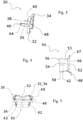
- a light module 2 also comprises at least one primary optical device 50 as illustrated in figure 4 , capable of being arranged directly opposite the light source 4, between the latter and the shaping lens 6.
- this primary optical device 50 participates both in the formation of a light beam of the main beam type, by guiding the light rays inside the optical device, than to the formation of a light beam of the dipped beam type, by cutting off the rays treated elsewhere by another primary optical device.
- the primary optical device 50 comprises a part 52 for receiving the light emitted by the second subset of light sources 26, a guide body 53 extending longitudinally and having at its free end, i.e.
- the guide body 53 has the shape of a block delimited by main faces 56 and lateral faces 58 making it possible to guide the light emanating from the reception part 52 towards the exit face 54 and towards the shaping lens 6.
- At least one main face 56 namely the main face facing the side of the first subset of light sources 24, can be provided with an opaque or reflective coating, aiming to cut the rays emitted by the first subset of light sources 24.
- the primary optical device 50 also comprises two legs 66 arranged respectively in the extension of a lateral face 58, on either side of the reception part 52.
- Each leg 66 comprises on its free end, opposite the guide body 53, a tab 67 forming an elbow and having a contact face with the first face 14 of the base 10.
- the tab 67 comprises, projecting from this contact face, a pin 68 configured to fit into an orifice formed in the first face 14 of the base 10 (not visible in the figures).
- the insertion of the pins 68 into the base 10 facilitates the positioning on the base 10 of the assembly formed by the pre-assembly of the frame 32 and the primary optical device 50, while ensuring that the receiving part 52 of the device primary optical device 50 is correctly positioned with respect to the second subset of light sources 26.
- the primary optical device 50 is then held against the first face 14 of the base 10 via the frame 32.
- a set of primary optical devices configured to be respectively opposite a subset of light sources has been made visible, with additional optical devices arranged on either side of the primary optical device described above.
- additional optical devices one can distinguish a first additional primary optical device 71, arranged opposite the first subset of light sources 24, and a second additional primary optical device 72 arranged opposite the third subset of light sources 28.
- the first and second additional primary optical devices 71, 72 for example take the form of collimators, each collimator being arranged to collect at least some of the light rays from the light sources and to redirect said light rays to the shaping lens 6.
- first and second additional primary optical devices 71, 72 may comprise retaining lugs 74 configured to fit into the notches 48 formed in the first face 34 of the frame 32, in order to ensure their position by clamping against the base 10 by said frame 32.
- the additional primary devices 71, 72 are held against the first face 14 of the base 10 via the frame 32 of the chassis 30.
- a light module equipped with such a set of optical devices allows in particular the formation of a beam of the dipped beam type by the emission of light rays through the first additional primary optical device 71, and the formation of a beam of high beam type by the simultaneous emission of light rays through each of the primary optical devices of the module.
- the primary optical device described above in the form of a block, participates on the one hand in guiding the light rays emitted by the second subset of light sources 26 as far as the exit face 54 and on the other hand in cutting rays which propagate between the first additional primary optical device 71 and the shaping lens 6.
- the presence of the arm 36 and the holding means arranged between this arm and the primary optical device is necessary in this context, where the primary optical device is elongated so that the output face, opposite the base 10, is arranged at a great distance from this base.
- the dimension between the base 10 and the output face of the primary optical device otherwise called the length L of the primary optical device, is greater than the dimension of this primary optical device along any parallel axis. to the plane defining the first face 14 of the base 10, and for example its thickness E visible on the figure 8 .
- This second embodiment differs from the above in that the arms 136 are here integral with the base 10, so as to form a one-piece assembly, instead of being carried by an independent frame. It is understood that the arm extends projecting from the base at a greater distance from the primary optical device than when this arm is carried by a frame capable of covering the lugs extending this primary optical device. In the example shown, the arms are arranged on the base on the periphery of these tabs, so as not to interfere with their attachment to the base.
- the primary optical device 50 comprises at least one bar 76 extending projecting from the side face 58, over a sufficient distance to come into taken in a slot 78 made in the corresponding arm 136.
- each arm 136 comprises, in the vicinity of the free end, such a slot 78, each slot having a shape and dimensions complementary to those of the bar 76 arranged projecting from the side face 58 of the primary optical device. 50.
Description
La présente invention a trait au domaine des modules lumineux utilisés pour l'éclairage et/ou la signalisation de véhicules automobiles (voir par exemple le document
Les projecteurs automobiles sont habituellement composés d'un boîtier qui est fermé par une paroi transparente à travers laquelle passent un ou plusieurs faisceaux lumineux. Ce boîtier loge au moins un module lumineux, comprenant principalement une source de lumière et un système optique configuré pour conformer la lumière générée par la source de lumière afin d'offrir des prestations spécifiques d'éclairage et/ou de signalisation du véhicule. Par exemple, le système optique peut être configuré pour permettre la projection en sortie du projecteur d'un faisceau lumineux dit de croisement, afin notamment de limiter l'éblouissement pour les conducteurs des véhicules circulant en sens inverse.Automotive headlamps usually consist of a housing which is closed by a transparent wall through which one or more light beams pass. This box houses at least one light module, mainly comprising a light source and an optical system configured to conform the light generated by the light source in order to provide specific lighting and/or signaling services for the vehicle. For example, the optical system can be configured to allow the projection at the output of the headlight of a so-called dipped light beam, in order in particular to limit glare for the drivers of vehicles traveling in the opposite direction.
Afin de réaliser cette fonction de feux de croisement, le module lumineux comprend au moins une source de lumière, un dispositif optique primaire positionné en vis-à-vis de la source de lumière pour guider les rayons lumineux, un élément de cache pouvant former une coupure des rayons lumineux émis afin de former un faisceau lumineux partiel susceptible de ne pas éblouir les tiers en sortie du projecteur, et une lentille de mise en forme de ces rayons pour former le faisceau lumineux en sortie du projecteur. On comprend que l'élément de cache est agencé sur le chemin des rayons, à distance de la source de lumière et qu'il convient de s'assurer de la position de celui-ci dans le long terme afin que la forme donnée aux rayons pour le faisceau lumineux dit de croisement soit stable dans le temps.In order to perform this dipped beam function, the light module comprises at least one light source, a primary optical device positioned opposite the light source to guide the light rays, a cover element that can form a cutting of the light rays emitted in order to form a partial light beam capable of not dazzling third parties at the output of the headlamp, and a lens for shaping these rays to form the light beam at the output of the headlamp. It is understood that the masking element is arranged on the path of the rays, at a distance from the light source and that it is necessary to ensure the position of the latter in the long term so that the shape given to the rays for the so-called crossing light beam is stable over time.
Par ailleurs, des modules lumineux additionnels peuvent être associés dans un même projecteur pour réaliser une fonction de feux de route, susceptible d'éclairer une scène de route avec une longue portée, lorsque le risque d'éblouissement de tiers n'est pas présent. Ces modules lumineux additionnels comportent là encore une ou plusieurs sources de lumière et un dispositif optique primaire associé avec une lentille de mise en forme pour la projection des rayons.Furthermore, additional light modules can be associated in the same headlamp to perform a main beam function, capable of illuminating a road scene with a long range, when the risk of dazzling third parties is not present. These additional light modules again comprise one or more light sources and a primary optical device associated with a shaping lens for the projection of the rays.
Par souci de compacité, il est prévu des modules lumineux dans lesquels ces deux fonctions sont réalisées, les sources lumineuses et les dispositifs optiques primaires devant être agencés les uns par rapport aux autres pour réaliser ces différentes fonctions selon l'allumage de l'une et/ou l'autre des sources lumineuses. Des premières sources lumineuses sont allumées lorsqu'il convient d'émettre un premier faisceau de type feu de croisement, et des secondes sources lumineuses sont allumées en complément pour émettre un faisceau complémentaire à ce premier faisceau pour former par combinaison des deux faisceaux un faisceau de type feu de route.For the sake of compactness, light modules are provided in which these two functions are performed, the light sources and the primary optical devices having to be arranged relative to each other to perform these different functions according to the switching on of one and /or the other of the light sources. First light sources are switched on when it is appropriate to emit a first beam of the dipped beam type, and second light sources are switched on in addition to emit a beam complementary to this first beam to form, by combining the two beams, a beam of high beam type.
De tels agencements peuvent impliquer la mise en place de dispositifs optiques primaires, et/ou d'élément de cache, qui présentent une face d'extrémité distale à distance d'une base formant support des sources de lumière. On comprend que les jeux de fabrication de ces dispositifs optiques primaires, réalisés en série, peuvent générer un défaut de positionnement. Un défaut de fabrication au niveau de la base du dispositif optique primaire, et notamment à l'endroit où la base va être fixée au support, peut entrainer un mauvais positionnement du dispositif et ce, d'autant plus que le porte-à-faux est grand. Par ailleurs, il est apparu que les vibrations mécaniques et les variations de température auxquelles le module lumineux est exposé lors de son utilisation peuvent entrainer au cours du temps une variation de l'inclinaison plus ou moins prononcée de ces dispositifs optiques primaires par rapport à la source de lumière. Cette inclinaison a pour inconvénient de modifier la zone éclairée par le feu de croisement ce qui peut s'avérer désagréable voire dangereux pour les conducteurs des véhicules circulant en sens inverse. Il s'avère alors nécessaire de procéder à un entretien régulier du module lumineux afin de corriger ce défaut pour prévenir de tout accident.Such arrangements may involve the placement of primary optical devices, and/or of a masking element, which have a distal end face at a distance from a base forming a support for the light sources. It is understood that the manufacturing clearances of these primary optical devices, produced in series, can generate a positioning error. A manufacturing defect at the base of the primary optical device, and in particular at the place where the base will be fixed to the support, can lead to poor positioning of the device, especially since the overhang is tall. Moreover, it appeared that the mechanical vibrations and the temperature variations to which the light module is exposed during its use can cause over time a variation in the more or less pronounced inclination of these primary optical devices with respect to the light source. This inclination has the disadvantage of modifying the area illuminated by the dipped headlights, which can prove to be unpleasant or even dangerous for the drivers of vehicles traveling in reverse. It is then necessary to carry out regular maintenance of the light module in order to correct this defect to prevent any accident.
L'invention propose de réaliser un module lumineux comprenant un dispositif optique primaire dont la position est moins susceptible de varier au cours du temps vis-à-vis de la source lumineuse du module lumineux.The invention proposes to produce a light module comprising a primary optical device whose position is less likely to vary over time with respect to the light source of the light module.
Dans ce but, l'invention a pour objet un module lumineux pour l'éclairage et/ou la signalisation d'un véhicule automobile selon la revendication 1. Par les termes « partie de réception » et « face de sortie », on entend respectivement la partie du dispositif optique primaire éclairée par la source de lumière et la face du dispositif optique primaire par laquelle cette lumière est émise en direction d'une lentille de mise en forme.To this end, the subject of the invention is a light module for the lighting and/or signaling of a motor vehicle according to claim 1. The terms “receiving part” and “output face” are understood to mean respectively the part of the primary optical device illuminated by the light source and the face of the primary optical device through which this light is emitted in the direction of a shaping lens.
Entre autre caractéristiques, le module lumineux selon l'invention comporte au moins un bras s'étendant en saillie de la première face de la base et maintenant le dispositif optique primaire au niveau d'une zone de maintien située entre la partie de réception et la face de sortie du dispositif optique primaire. De la sorte, il est possible de limiter ou empêcher l'inclinaison du dispositif optique primaire par rapport à la base et d'assurer une position fiable du dispositif optique primaire dans le module lumineux.Among other features, the light module according to the invention comprises at least one arm projecting from the first face of the base and holding the primary optical device at the level of a holding zone located between the receiving part and the exit face of the primary optical device. In this way, it is possible to limit or prevent the inclination of the primary optical device with respect to the base and to ensure a reliable position of the primary optical device in the light module.
Selon différentes caractéristiques de l'invention, prises seules ou en combinaison, on pourra prévoir que :
- La zone de maintien est plus proche de la face de sortie que de la partie de réception du dispositif optique primaire. De préférence, le centre de la zone de maintien est situé à une distance de la face d'émission égale ou inférieure à un quart de la distance séparant les faces de réception et d'émission du dispositif optique primaire, de préférence à une distance égale ou inférieure à un huitième de cette distance.
- Le bras et le dispositif optique primaire comportent des organes complémentaires pour coopérer dans ladite zone de maintien. Les organes sont complémentaires en ce que leur forme permet une coopération empêchant le déplacement du dispositif optique primaire par rapport au bras.
- Les organes complémentaires comportent une ouverture ménagée sur une face intérieure du bras en vis-à-vis du dispositif optique primaire et un ergot ménagé sur une face latérale du dispositif optique primaire. On comprend que selon une variante de réalisation, on pourrait prévoir que le bras comprenne un appendice au niveau de sa face intérieure, configuré pour s'emboîter dans une encoche présente sur une face latérale en regard du dispositif optique primaire.
- Le bras comprend une rainure ménagée au niveau d'une face intérieure en vis-à-vis du dispositif optique primaire, de manière à faciliter le guidage du dispositif optique primaire le long du bras lors de leur assemblage.
- L'ouverture est agencée dans le prolongement de la rainure.
- Les bras ont une élasticité suffisante pour permettre leur écartement pour faciliter la coopération des organes complémentaires, et notamment le passage de l'ergot de la rainure à l'ouverture. La rainure peut être délimitée par un plan incliné au niveau de l'ouverture, de manière à faciliter le passage de l'ergot hors de la rainure.
- Le module lumineux comprend au moins un châssis rendu solidaire de la base, le châssis comprenant le ou les bras.
- Le châssis forme un cadre s'étendant partiellement autour de la source de lumière. Dans ce contexte, le module lumineux peut comporter au moins deux châssis distincts positionnés de sorte à maintenir le dispositif optique primaire au niveau de deux faces opposées.
- Le châssis forme un cadre s'étendant tout autour de la source de lumière.
- Le cadre du châssis est en contact avec la première face de la base, les bras s'étendant depuis le cadre à l'opposé de ladite première face de la base.
- Le cadre est maintenu contre la première face de la base par l'intermédiaire de moyens de fixation réversibles, par exemple des vis. Selon une variante de réalisation, le cadre est collé contre la première face de la base. Il peut également, sans sortir du contexte de l'invention, être assemblé par déformation de matière, et par exemple par sertissage et bouterollage.
- Le ou les bras sont venus de matière avec la base, de manière à former un ensemble monobloc. Par ensemble monobloc, on comprend que les bras et la base sont solidaires et d'un seul tenant, et que leur séparation ne peut être effectuée que par détérioration et cassure de l'un et/ou de l'autre.
- Au moins un bras comporte au voisinage de son extrémité libre une fente de forme et de dimensions complémentaires de celles d'un barreau agencé en saillie de la face latérale du dispositif optique primaire.
- La source de lumière comprend au moins une diode électroluminescente plaquée directement ou via une pâte thermiquement conductrice contre la base et au moins un conducteur électrique reliant la diode électroluminescente à une source électrique. La pâte thermiquement conductrice peut être par exemple une colle ou un adhésif thermique.
- La source de lumière comprend au moins un premier sous-ensemble de sources de lumière et un deuxième sous-ensemble de sources de lumière, un dispositif optique primaire additionnel étant en regard du premier sous-ensemble de sources de lumière et le dispositif optique primaire étant en regard du deuxième sous-ensemble de sources de lumière.
- Le dispositif optique primaire additionnel comprend au moins une patte de maintien formant saillie du corps du dispositif.
- Le cadre présente une première face agencée contre la première face de la base, ladite première face présentant au moins une encoche pour recevoir une patte de maintien du dispositif optique primaire ou dispositif optique primaire additionnel.
- Le dispositif optique primaire et/ou le dispositif optique primaire additionnel est maintenu contre la première face de la base par l'intermédiaire du cadre du châssis.
- Le châssis est réalisé en un matériau thermiquement conducteur. Selon un exemple, un tel matériau est un métal ou un matériau synthétique thermiquement conducteur.
- The holding zone is closer to the exit face than to the reception part of the primary optical device. Preferably, the center of the holding zone is located at a distance from the emission face equal to or less than a quarter of the distance separating the reception and emission faces of the primary optical device, preferably at a distance equal or less than one-eighth of that distance.
- The arm and the primary optical device comprise complementary members for cooperating in said holding zone. The members are complementary in that their shape allows cooperation preventing the displacement of the primary optical device with respect to the arm.
- The complementary members comprise an opening formed on an inner face of the arm facing the primary optical device and a lug formed on a side face of the primary optical device. It is understood that according to a variant embodiment, provision could be made for the arm to comprise an appendix at its inner face, configured to fit into a notch present on a side face facing the primary optical device.
- The arm comprises a groove formed at an inner face facing the primary optical device, so as to facilitate the guiding of the primary optical device along the arm during their assembly.
- The opening is arranged in the extension of the groove.
- The arms have sufficient elasticity to allow their separation to facilitate the cooperation of the complementary members, and in particular the passage of the lug from the groove to the opening. The groove can be delimited by an inclined plane at the level of the opening, so as to facilitate the passage of the lug out of the groove.
- The light module comprises at least one frame secured to the base, the frame comprising the arm(s).
- The chassis forms a frame extending partially around the light source. In this context, the light module may comprise at least two separate frames positioned so as to maintain the primary optical device at two opposite faces.
- The chassis forms a frame extending all around the light source.
- The frame of the chassis is in contact with the first face of the base, the arms extending from the frame opposite said first face of the base.
- The frame is held against the first face of the base by means of reversible fastening means, for example screws. According to a variant embodiment, the frame is glued against the first face of the base. It can also, without departing from the context of the invention, be assembled by material deformation, and for example by crimping and riveting.
- The arm or arms are integral with the base, so as to form a one-piece assembly. By one-piece assembly, it is understood that the arms and the base are integral and in one piece, and that their separation can only be effected by deterioration and breakage of one and/or the other.
- At least one arm comprises near its free end a slot of shape and dimensions complementary to those of a bar arranged projecting from the side face of the primary optical device.
- The light source comprises at least one light-emitting diode plated directly or via a thermally conductive paste against the base and at least one electrical conductor connecting the light-emitting diode to an electrical source. The thermally conductive paste can for example be a glue or a thermal adhesive.
- The light source comprises at least a first subset of light sources and a second subset of light sources, an additional primary optical device facing the first subset of light sources and the primary optical device being next to the second subset of light sources.
- The additional primary optical device comprises at least one holding lug forming a projection from the body of the device.
- The frame has a first face arranged against the first face of the base, said first face having at least one notch to receive a retaining lug for the primary optical device or additional primary optical device.
- The primary optical device and/or the additional primary optical device is held against the first face of the base via the frame of the chassis.
- The frame is made of a thermally conductive material. According to one example, such a material is a metal or a thermally conductive synthetic material.
L'invention couvre également un projecteur de véhicule automobile comprenant au moins un module lumineux tel que décrit dans le présent document, dans sa forme la plus limitée ou comprenant une ou plusieurs des caractéristiques exposées ci-dessus.The invention also covers a motor vehicle headlamp comprising at least one light module as described in this document, in its most limited form or comprising one or more of the characteristics set out above.
D'autres caractéristiques, détails et avantages de l'invention ressortiront plus clairement à la lecture de la description donnée ci-après à titre indicatif en relation avec des dessins dans lesquels :
- la
figure 1 est une vue en perspective d'un module lumineux selon l'invention, rendant notamment visible une base, un support et une lentille de mise en forme ; - la
figure 2 est une vue en perspective et partielle d'un module lumineux illustré à lafigure 1 , dans laquelle on a retiré notamment le support et la lentille de mise en forme, pour rendre visible la base et la source de lumière qu'elle porte, ainsi qu'un châssis configuré pour coopérer avec un dispositif optique primaire ici non illustré ; - la
figure 3 est une vue en perspective du châssis du module lumineux de lafigure 2 ; - la
figure 4 est une vue en perspective d'un dispositif optique primaire apte à équiper le module lumineux de lafigure 2 , notamment pour former un ensemble avec le châssis de lafigure 3 ; - la
figure 5 est une vue en perspective d'un ensemble formé du dispositif optique primaire de lafigure 4 inséré dans le châssis de lafigure 3 ; - la
figure 6 est une vue similaire à celle de lafigure 2 , dans laquelle on a représenté l'ensemble de lafigure 5 , formé par le châssis et le dispositif optique primaire, monté sur la base du module lumineux ; - la
figure 7 est une vue en perspective du module lumineux de lafigure 1 , dans laquelle on a rendu visible, en plus des éléments présents dans lafigure 6 , des dispositifs optiques primaires additionnels ; - la
figure 8 est une vue en perspective similaire à celle de lafigure 6 , dans laquelle on a retiré notamment le châssis ; et - la
figure 9 est une vue d'un deuxième mode de réalisation, selon une perspective similaire à celle de lafigure 6 .
- the
figure 1 is a perspective view of a light module according to the invention, showing in particular a base, a support and a shaping lens; - the
picture 2figure 1 , in which the support and the shaping lens have been removed in particular, to make the base and the light source it carries visible, as well as a frame configured to cooperate with a primary optical device not shown here; - the
picture 3 is a perspective view of the chassis of the light module of thepicture 2 - the
figure 4 is a perspective view of a primary optical device capable of equipping the light module of thepicture 2picture 3 ; - the
figure 5 is a perspective view of an assembly consisting of the primary optical device of thefigure 4 inserted into the frame of thepicture 3 ; - the
figure 6 is a view similar to that of thefigure 2 , in which the whole of thefigure 5 , formed by the chassis and the primary optical device, mounted on the base of the light module; - the
figure 7 is a perspective view of the light module of thefigure 1 , in which we have made visible, in addition to the elements present in thefigure 6 , additional primary optical devices; - the
figure 8 is a perspective view similar to that of thefigure 6 , in which the chassis has been removed in particular; and - the
figure 9 is a view of a second embodiment, from a perspective similar to that of thefigure 6 .
Il faut tout d'abord noter que les figures exposent l'invention de manière détaillée pour mettre en œuvre l'invention, lesdites figures pouvant bien entendu servir à mieux définir l'invention le cas échéant.It should first be noted that the figures expose the invention in detail to implement the invention, said figures can of course be used to better define the invention if necessary.
Dans la suite de la description, les dénominations longitudinales ou latérales, dessus, dessous, devant, derrière se réfèrent à l'orientation du module lumineux 2 tel qu'il est destiné à être intégré dans un projecteur avant de véhicule automobile. Une direction longitudinale correspond à un axe optique A le long duquel les rayons lumineux générés par le module lumineux 2 s'étendent majoritairement. L'orientation latérale correspond à une droite perpendiculaire à l'axe optique A et qui s'étend horizontalement. Enfin, la direction verticale correspond à une orientation perpendiculaire à l'axe optique A et à l'orientation latérale.In the remainder of the description, the designations longitudinal or lateral, above, below, in front, behind refer to the orientation of the
La
Un tel module lumineux 2 forme un sous-ensemble unitaire, c'est-à-dire un objet qui peut remplir sa fonction sans autre apport que l'énergie électrique nécessaire à son allumage, et le cas échéant avec l'aide d'un module de régulation du courant électrique pour protéger le module des températures excessives.Such a
Le module lumineux 2 selon l'invention est agencé pour créer un faisceau de feu de croisement et un faisceau de feu de route. Tel que cela va être expliqué plus en détails ci-après, le module lumineux 2 est adapté pour que le faisceau route soit la combinaison du faisceau de feu de croisement avec un faisceau complémentaire qui éclaire au-dessus et/ou au-dessous du faisceau de feu de croisement, l'ensemble formant ainsi le faisceau de feu de route.The
Le module lumineux 2 comprend au moins une source de lumière 4 notamment visible sur la
La
Le support 8 est notamment formé par deux secteurs tubulaires longitudinalement consécutifs de section transversale différente. Un premier secteur tubulaire 12 prend appui contre une première face 14 de la base 10 tournée vers la lentille, tandis qu'un second secteur tubulaire 16 prolonge le premier secteur tubulaire 12 et forme une zone de réception de la lentille de mise en forme 6. Le premier secteur tubulaire 12 peut affleurer un organe de dissipation 18, destiné à évacuer du module lumineux 2 au moins une partie de la chaleur générée par la source de lumière 4. Le support 8 peut être rendu solidaire de la base 10 par la présence de vis plaquant le support 8 contre la première face 14 de la base 10.The
On va maintenant décrire un premier mode de réalisation, en se référant notamment aux
Selon le présent exemple, le module lumineux 2 comporte trois rangées de diodes électroluminescentes sensiblement parallèles entre elles. Chaque rangée forme ainsi un sous-ensemble de sources de lumière parmi lesquelles on peut distinguer un premier sous-ensemble de sources de lumière 24, un deuxième sous-ensemble de sources de lumière 26 et un troisième sous-ensemble de sources de lumière 28. On comprend que l'agencement illustré est donné à titre d'exemple, et que les diodes électroluminescentes pourraient par exemple être agencées pour former trois sous-ensembles fonctionnels sans qu'un agencement en rangées parallèles soit visible sur le module.According to the present example, the
Le premier sous-ensemble de sources de lumière 24 est chargé de créer les rayons lumineux pour un premier faisceau lumineux de type feu de croisement, le deuxième sous-ensemble de sources de lumière 26 est chargé de créer les rayons lumineux pour un faisceau lumineux complémentaire formant par addition avec le premier faisceau un deuxième faisceau de type feu de route, et le troisième sous-ensemble de sources de lumière 28 est chargé de créer les rayons lumineux pour surintensifier une zone centrale au niveau du bord du deuxième faisceau, à savoir le bord formant jonction avec le premier faisceau lorsque les deux faisceaux sont projetés simultanément.The first subset of
Dans l'exemple illustré, le premier sous-ensemble de sources de lumière 24 comprend six diodes électroluminescentes 22, sensiblement alignées selon une direction latérale. Le deuxième sous-ensemble de sources de lumière 26 et le troisième sous-ensemble de sources de lumière 28 comprennent respectivement quatre et deux diodes électroluminescentes 22 réparties sur deux lignes sensiblement latérales, le deuxième sous-ensemble de sources de lumière 26 étant positionné entre le premier sous-ensemble de sources de lumière 24 et le troisième sous-ensemble de sources de lumière 28.In the example illustrated, the first subset of
Chacun des sous-ensembles de sources de lumière 24, 26 et 28 est disposé contre la première face 14 de la base 10, en une zone centrale sur cette première face 14 tel que cela ressort de la
On va décrire dans ce qui suit la coopération entre le châssis 30, notamment visible sur les
Plus précisément, le châssis 30 illustré aux
Le cadre 32 présente une première face 34 destinée à être plaquée contre la première face 14 de la base 10 lorsque le cadre est fixé sur la base.The
Le châssis 30 comporte également deux bras 36 s'étendant depuis le cadre 32 en direction de la lentille de mise en forme 6 selon une direction longitudinale ou normale par rapport au plan défini par ce cadre 32. Il en résulte, lorsque le cadre 32 est fixé sur la base 10, que les bras 36 s'étendent principalement perpendiculairement à cette base 10. Les bras 36 s'étendent depuis des bords opposés du cadre 32, et ils sont plus particulièrement positionnés au niveau de chaque extrémité de la ligne latérale formée par le deuxième sous-ensemble de sources de lumière 26. Les bras 36 présentent respectivement une face intérieure 38 tournée vers le bras opposé, de telle sorte que les faces intérieures 38 des bras sont en vis-à-vis. Chaque face intérieure 38 comporte une rainure 40 s'étendant sur une partie du bras 36. Plus précisément, chaque rainure 40 s'étend pour déboucher sur la première face 34 du cadre comme illustré à la
Il convient de noter que les ouvertures et les ergots sont ici un exemple de réalisation d'organes complémentaires portés par les bras du châssis et par le dispositif optique primaire 50 tel qu'il va être décrit plus en détails ci-après, ces organes complémentaires présentant des formes configurées pour permettre ce blocage en position. Une fois les ergots 42 insérés dans les ouvertures 44 comme illustré sur les
La zone de maintien 62 est ici formée au voisinage de l'extrémité distale 46 de chaque bras, étant entendu qu'elle pourrait être ménagée plus ou moins loin de la face de sortie 54 par rapport à ce qui est illustré. Il est toutefois souhaitable que cette zone de maintien, pour assurer une stabilité du dispositif, soit agencée plus près de la face de sortie 54 en bout du corps de guidage 53 du dispositif optique primaire que de la partie de réception 52 de ce dispositif optique primaire 50.The holding
Il est à noter que le châssis 30 comporte au niveau de sa première face 34 des encoches 48, configurées pour délimiter des espaces de réception de pattes 74 solidaires d'éléments optiques, comme cela sera décrit ci-dessous.It should be noted that the
Tel que cela a pu être évoqué précédemment, un module lumineux 2 selon l'invention comprend également au moins un dispositif optique primaire 50 tel qu'illustré à la
Tel que cela sera décrit ci-après plus en détails, au moins une face principale 56, à savoir la face principale tournée du côté du premier sous-ensemble de sources de lumière 24, peut être munie d'un revêtement opaque ou réfléchissant, visant à couper les rayons émis par le premier sous-ensemble de sources de lumière 24.As will be described below in more detail, at least one
Il est à noter que le dispositif optique primaire 50 selon l'invention comporte également deux jambes 66 disposées respectivement dans le prolongement d'une face latérale 58, de part et d'autre de la partie de réception 52. Chaque jambe 66 comprend à son extrémité libre, à l'opposé du corps de guidage 53, une patte 67 formant un coude et présentant une face de contact avec la première face 14 de la base 10. La patte 67 comporte, en saillie de cette face de contact, un pion 68 configuré pour s'insérer dans un orifice ménagé dans la première face 14 de la base 10 (non visible sur les figures). L'insertion des pions 68 dans la base 10 facilite le positionnement sur la base 10 de l'ensemble formé par le pré-assemblage du cadre 32 et du dispositif optique primaire 50, tout en s'assurant que la partie de réception 52 du dispositif optique primaire 50 soit correctement positionnée par rapport au deuxième sous-ensemble de sources de lumière 26. Le dispositif optique primaire 50 est alors maintenu contre la première face 14 de la base 10 par l'intermédiaire du cadre 32. A titre d'exemple illustratif, on peut se référer à la
De fait, il suffit à l'opérateur de maintenir le cadre 32 à la base 10 par l'intermédiaire de vis 20 comme illustré à la
Sur la
Un module lumineux équipé d'un tel ensemble de dispositifs optiques permet notamment la formation d'un faisceau de type feu de croisement par l'émission de rayons lumineux à travers le premier dispositif optique primaire additionnel 71, et la formation d'un faisceau de type feu de route par l'émission simultanée de rayons lumineux à travers chacun des dispositifs optiques primaires du module. Le dispositif optique primaire, décrit précédemment en forme de pavé, participe d'une part au guidage des rayons lumineux émis par le deuxième sous-ensemble de sources de lumière 26 jusqu'à la face de sortie 54 et d'autre part à la coupure des rayons qui se propagent entre le premier dispositif optique primaire additionnel 71 et la lentille de mise en forme 6.A light module equipped with such a set of optical devices allows in particular the formation of a beam of the dipped beam type by the emission of light rays through the first additional primary
Dans ce contexte illustré sur la
On comprend que la présence du bras 36 et des moyens de maintien agencés entre ce bras et le dispositif optique primaire est nécessaire dans ce contexte, où le dispositif optique primaire est allongé de sorte que la face de sortie, à l'opposé de la base 10, est agencée à une grande distance de cette base. Par grande distance, on comprend que la dimension entre la base 10 et la face de sortie du dispositif optique primaire, autrement appelée longueur L du dispositif optique primaire, est plus grande que la dimension de ce dispositif optique primaire selon n'importe quel axe parallèle au plan définissant la première face 14 de la base 10, et par exemple son épaisseur E visible sur la
La présence d'au moins un bras et des moyens de maintien a été décrite selon un premier mode de réalisation dans ce qui précède, mais il est entendu que d'autres modes de réalisation peuvent être mis en œuvre, et par exemple le deuxième mode de réalisation illustré sur la
Ce deuxième mode de réalisation diffère de ce qui précède en ce que les bras 136 sont ici venus de matière avec la base 10, de manière à former un ensemble monobloc, au lieu d'être porté par un châssis indépendant. On comprend que le bras s'étend en saillie de la base à une plus grande distance du dispositif optique primaire que lorsque ce bras est porté par un châssis susceptible de recouvrir les pattes prolongeant ce dispositif optique primaire. Dans l'exemple illustré, les bras sont agencés sur la base en périphérie de ces pattes, de manière à ne pas gêner leur fixation sur la base.This second embodiment differs from the above in that the
Dès lors, pour faire coopérer les bras 136 et le dispositif optique primaire dans la zone de maintien 162, le dispositif optique primaire 50 comporte au moins un barreau 76 s'étendant en saillie de la face latérale 58, sur une distance suffisante pour venir en prise dans une fente 78 réalisée dans le bras 136 correspondant.Therefore, to make the
Dans l'exemple illustré, chaque bras 136 comporte, au voisinage de l'extrémité libre, une telle fente 78, chaque fente présentant une forme et des dimensions complémentaires de celles du barreau 76 agencé en saillie de la face latérale 58 du dispositif optique primaire 50.In the example illustrated, each
La description qui précède explique clairement comment l'invention permet d'atteindre les objectifs qu'elle s'est fixés et notamment de proposer un module lumineux permettant un maintien plus aisé et plus sûr au cours du temps d'un dispositif optique primaire en vis-à-vis d'une source de lumière d'un module lumineux. En effet, l'utilisation d'un châssis selon l'invention permet de s'assurer que la position ainsi que l'inclinaison de dispositif optique primaire vis-à-vis de la source de lumière ne varie pas au cours du temps en fonction des vibrations et/ou des variations de température subies par le module lumineux. C'est pourquoi la présente invention propose un module lumineux plus sûr d'utilisation.The foregoing description clearly explains how the invention makes it possible to achieve the objectives it has set itself and in particular to propose a light module allowing easier and safer maintenance over time of a primary optical device in screw -towards a light source of a light module. Indeed, the use of a frame according to the invention makes it possible to ensure that the position as well as the inclination of the primary optical device with respect to the light source does not vary over time depending vibrations and/or temperature variations experienced by the light module. This is why the present invention proposes a light module that is safer to use.
Claims (15)
- Lighting module (2) for illumination and/or signalling in a motor vehicle, comprising a base (10) supporting at a first face (14) at least one light source (4) that emits light rays, most of which extend along an optical axis perpendicular or substantially perpendicular to the first face (14), and a primary optical device (50) comprising a receiving portion (52) opposite at least one portion of the light source (4) and lightened by the light source (4) and an output face (54) opposite the receiving portion (52), the lighting module (2) having at least one arm (36, 136) projecting from the first face (14) of the base (10) and holding the primary optical device (50) at a retaining zone (62,162) positioned between the receiving portion (52) and the output face (54) of the primary optical device (50), said arm (36, 136) may be arranged to face a lateral face (58) of the primary optical device (50), characterized in that the primary optical device (50) has two struts (66) extending a side face (58) on both sides of the receiving portion (52) respectively, each strut (66) having a foot (67) provided with a pin (68) designed to cooperate with an orifice formed in the base (10), thus ensuring the positioning of the receiving portion (52) of the primary optical device (50) relative to the light source (4).
- Lighting module (2) according to the preceding claim, characterized in that the primary optical device (50) further comprises a guide member (53) being tile-shaped and delimited by the main faces (56) and the lateral faces (58), enabling the light emitted from the receiving portion (52) to be guided towards the output face (54) and in that each strut (66) has the foot (67) at the free end thereof opposite the guide member (53), said foot (67) forming an elbow and having a contact face with the first face (14) of the base (10).
- Lighting module (2) according to Claim 1 or 2, characterized in that the retaining zone (62,162) is closer to the output face (54) than the receiving portion (52) of the primary optical device (50).
- Lighting module (2) according to one of the preceding claims, characterized in that the arm (36, 136) and the primary optical device (50) have matching members that cooperate in said retaining zone (62, 162).
- Lighting module (2) according to the preceding claim, characterized in that the matching members are an opening (44) formed on an inner face (38) of the arm (36) opposite the primary optical device (50) and a lug (42) formed on a lateral face (58) of the primary optical device (50).
- Lighting module (2) according to one of the preceding claims, characterized in that the arm (36) has a groove (40) formed in an inner face (38) opposite the primary optical device (50) to help guide the primary optical device (50) along the arm (36) during assembly thereof.
- Lighting module (2) according to Claims 5 and 6, characterized in that the opening (44) extends the groove (40).
- Lighting module (2) according to one of the preceding claims, characterized in that the lighting module (2) has at least one chassis (30) rigidly connected to the base (10), the chassis (30) including the arm or arms (36).
- Lighting module (2) according to the preceding claim, characterized in that the chassis (30) forms a frame (32) extending partially about the light source (4).
- Lighting module (2) according to Claim 8, characterized in that the chassis (30) forms a frame (32) extending entirely about the light source (4).
- Lighting module (2) according to Claim 9 or 10, characterized in that the frame (32) of the chassis (30) is in contact with the first face (14) of the base (10), the arms (36) extending from the frame (32) opposite said first face (14) of the base (10).
- Lighting module according to one of Claims 1 to 7, characterized in that the arm or arms (136) are integrally formed with the base (10) such as to form a one-piece assembly.
- Lighting module according to the preceding claim, in combination with Claim 2, characterized in that at least one arm (136) has, in the vicinity of the free end thereof, a slot (78) shaped and dimensioned to match the shape and dimensions of a bar (76) projecting from the lateral face (58) of the primary optical device (50).
- Lighting module (2) according to one of the preceding claims, characterized in that the light source (4) includes at least one first light-source sub-assembly (24) and one second light-source sub-assembly (26), an additional primary optical device (71) being arranged to face the first light-source sub-assembly (24) and the primary optical device (50) being arranged to face the second light-source sub-assembly.
- Lighting module (2) according to claim 14, characterized in that the additional primary optical device (71) is held against the first face (14) of the base (10) by the frame (32) of the chassis (30).
Applications Claiming Priority (1)
| Application Number | Priority Date | Filing Date | Title |
|---|---|---|---|
| FR1761222A FR3074257B1 (en) | 2017-11-27 | 2017-11-27 | LIGHT MODULE FOR LIGHTING AND / OR SIGNALING OF A MOTOR VEHICLE |
Publications (2)
| Publication Number | Publication Date |
|---|---|
| EP3489576A1 EP3489576A1 (en) | 2019-05-29 |
| EP3489576B1 true EP3489576B1 (en) | 2022-03-16 |
Family
ID=61873396
Family Applications (1)
| Application Number | Title | Priority Date | Filing Date |
|---|---|---|---|
| EP18208370.9A Active EP3489576B1 (en) | 2017-11-27 | 2018-11-26 | Light module for lighting and/or signalling of a motor vehicle |
Country Status (4)
| Country | Link |
|---|---|
| US (1) | US11098870B2 (en) |
| EP (1) | EP3489576B1 (en) |
| CN (1) | CN110030528A (en) |
| FR (1) | FR3074257B1 (en) |
Families Citing this family (7)
| Publication number | Priority date | Publication date | Assignee | Title |
|---|---|---|---|---|
| DE102019118968A1 (en) | 2019-07-12 | 2021-01-14 | HELLA GmbH & Co. KGaA | Projection headlights for vehicles |
| FR3103877B1 (en) * | 2019-11-28 | 2022-07-08 | Valeo Vision | Optical element and light module of a motor vehicle equipped with such an optical element |
| FR3104678B1 (en) * | 2019-12-11 | 2021-12-10 | Valeo Vision | Lighting device of a motor vehicle |
| FR3113107B1 (en) * | 2020-07-30 | 2022-09-02 | Psa Automobiles Sa | Downstream box for optical module intended to equip a motor vehicle |
| EP3971469A1 (en) * | 2020-09-22 | 2022-03-23 | Varroc Engineering Limited | A vehicle headlamp assembly |
| US11519582B2 (en) | 2021-04-07 | 2022-12-06 | Ford Global Technologies, Llc | High efficiency vehicle backup lamps |
| EP4191127A1 (en) | 2021-12-02 | 2023-06-07 | ZKW Group GmbH | Illumination device for a motorcycle headlamp |
Family Cites Families (24)
| Publication number | Priority date | Publication date | Assignee | Title |
|---|---|---|---|---|
| JP4428223B2 (en) * | 2004-12-07 | 2010-03-10 | 市光工業株式会社 | Vehicle lamp and vehicle headlamp device |
| US20090016074A1 (en) * | 2007-07-09 | 2009-01-15 | Magna International Inc. | Semiconductor light engine using glass light pipes |
| US8157414B2 (en) * | 2009-01-30 | 2012-04-17 | Koninklijke Philips Electronics N.V. | LED optical assembly |
| DE102009034841B4 (en) * | 2009-07-27 | 2020-11-26 | Emz-Hanauer Gmbh & Co. Kgaa | Light emitting device for a drum of a household appliance |
| DE102010023359A1 (en) * | 2009-10-05 | 2011-04-07 | Automotive Lighting Reutlingen Gmbh | Motor vehicle headlight with a temperature expansion compensating optics bracket |
| WO2012014360A1 (en) * | 2010-07-26 | 2012-02-02 | 株式会社小糸製作所 | Light-emitting module |
| EP2598797B1 (en) * | 2010-07-26 | 2021-01-20 | Valeo Vision | Optical module of an illuminating and/or signalling device of a motor vehicle |
| JP5538307B2 (en) * | 2011-06-21 | 2014-07-02 | 本田技研工業株式会社 | Lamp body and vehicle lamp unit |
| US9937852B2 (en) * | 2012-01-13 | 2018-04-10 | JST Performance, LLC | Light fixture with curved frame |
| DE102013206489A1 (en) * | 2013-04-11 | 2014-10-30 | Automotive Lighting Reutlingen Gmbh | Light module of a motor vehicle lighting device |
| JP6261276B2 (en) * | 2013-10-11 | 2018-01-17 | 株式会社小糸製作所 | Vehicle lighting |
| CN105090852B (en) * | 2014-05-09 | 2018-10-16 | 松下知识产权经营株式会社 | Lighting device and the automobile for having lighting device |
| US20170227184A1 (en) * | 2014-08-07 | 2017-08-10 | Koito Manufacturing Co., Ltd. | Vehicle lamp |
| JP2016058166A (en) * | 2014-09-05 | 2016-04-21 | 株式会社小糸製作所 | Vehicular lighting fixture |
| FR3026462B1 (en) * | 2014-09-30 | 2019-06-28 | Valeo Vision Belgique | VEHICLE LIGHT DEVICE WITH PLATE OPTICAL ELEMENT WITH LIGHT SOURCE SUPPORT |
| WO2016066908A1 (en) * | 2014-10-31 | 2016-05-06 | Peugeot Citroen Automobiles Sa | Compact optical module for vehicle |
| CN104566215B (en) | 2014-12-24 | 2017-12-29 | 上海小糸车灯有限公司 | A kind of vehicle light illumination local aluminizing lens |
| JP6600987B2 (en) | 2015-05-21 | 2019-11-06 | 市光工業株式会社 | Vehicle lighting |
| JP6440841B2 (en) | 2015-06-15 | 2018-12-19 | 三菱電機株式会社 | In-vehicle light source unit |
| CN105570794B (en) * | 2016-02-23 | 2018-02-06 | 上海小糸车灯有限公司 | PES unit of the car light LED distance-lights one with ADB functions |
| JP6741467B2 (en) * | 2016-05-12 | 2020-08-19 | 株式会社小糸製作所 | Vehicle lighting |
| DE102016114346A1 (en) * | 2016-08-03 | 2018-02-08 | HELLA GmbH & Co. KGaA | Optical system with a light guide and with a material connected to the light guide body |
| US10247383B2 (en) * | 2017-08-29 | 2019-04-02 | Osram Sylvania Inc. | Vehicle lamp with articulated multi-piece heat sink |
| JP6955418B2 (en) * | 2017-10-13 | 2021-10-27 | 株式会社小糸製作所 | Vehicle lighting |
-
2017
- 2017-11-27 FR FR1761222A patent/FR3074257B1/en active Active
-
2018
- 2018-11-26 EP EP18208370.9A patent/EP3489576B1/en active Active
- 2018-11-27 US US16/201,377 patent/US11098870B2/en active Active
- 2018-11-27 CN CN201811429810.3A patent/CN110030528A/en active Pending
Non-Patent Citations (1)
| Title |
|---|
| None * |
Also Published As
| Publication number | Publication date |
|---|---|
| CN110030528A (en) | 2019-07-19 |
| FR3074257B1 (en) | 2020-11-13 |
| FR3074257A1 (en) | 2019-05-31 |
| EP3489576A1 (en) | 2019-05-29 |
| US11098870B2 (en) | 2021-08-24 |
| US20190162380A1 (en) | 2019-05-30 |
Similar Documents
| Publication | Publication Date | Title |
|---|---|---|
| EP3489576B1 (en) | Light module for lighting and/or signalling of a motor vehicle | |
| EP3067618B1 (en) | Light-emitting device with optical waveguides | |
| CA2810385C (en) | Optical module of an illuminating and/or signalling device of a motor vehicle | |
| EP2775197A1 (en) | Lighting and/or signalling device for a motor vehicle comprising a light guide | |
| CA2810700C (en) | Optical module of an illuminating and/or signalling device of a motor vehicle | |
| EP4065882B1 (en) | Light module of a motor vehicle equipped with an optical element | |
| EP2966343B1 (en) | Lighting module for a motor vehicle headlight with positioning means between heat sink and reflector/circuit board | |
| EP2921772B1 (en) | Light module of a motor vehicle | |
| EP3299710B1 (en) | Luminous module and luminous device for motor vehicle comprising such a luminous module | |
| EP2966344B1 (en) | Optical module with lens for motor vehicle projector headlamp | |
| FR3022974A1 (en) | LIGHTING MODULE FOR AUTOMOTIVE PROJECTOR WITH POSITIONING BETWEEN REFLECTOR AND LENS | |
| FR3062460A1 (en) | LUMINOUS MODULE FOR VEHICLE PROJECTOR | |
| EP2295850A1 (en) | Lighting and/or signalling device for an automobile | |
| EP3104074A1 (en) | Positioning device of a led support on a support element and illumination or signalisation device comprising such a device | |
| EP3486554B1 (en) | Lighting module for vehicle headlamp | |
| FR3056698B1 (en) | LUMINOUS MODULE FOR MOTOR VEHICLE | |
| FR2691683A1 (en) | Signaling light for motor vehicles. | |
| EP3502546B1 (en) | Light module for a vehicle comprising a ventilation device arranged between two devices for heat dissipation | |
| EP3502548B1 (en) | Light module for vehicle headlight | |
| FR3088869A1 (en) | Device for pre-positioning and holding an element on a box | |
| FR3064721B1 (en) | LUMINOUS DEVICE WITH RADIATOR CROSSING THE HOUSING | |
| FR3106651A1 (en) | Flat light guide for motor vehicle signaling light module | |
| FR3022011A1 (en) | LIGHT-EMITTING DEVICE FOR CARRYING OUT A SIGNALING AND / OR LIGHTING FUNCTION OF A MOTOR VEHICLE | |
| FR2973477A1 (en) | Mechanism for adjusting cut of e.g. optical module of left headlight of car, has compensation device for compensating axial play of cutting unit that rotates with respect to frame, and exerting force on unit in direction of rotational axis |
Legal Events
| Date | Code | Title | Description |
|---|---|---|---|
| PUAI | Public reference made under article 153(3) epc to a published international application that has entered the european phase |
Free format text: ORIGINAL CODE: 0009012 |
|
| STAA | Information on the status of an ep patent application or granted ep patent |
Free format text: STATUS: REQUEST FOR EXAMINATION WAS MADE |
|
| 17P | Request for examination filed |
Effective date: 20181126 |
|
| AK | Designated contracting states |
Kind code of ref document: A1 Designated state(s): AL AT BE BG CH CY CZ DE DK EE ES FI FR GB GR HR HU IE IS IT LI LT LU LV MC MK MT NL NO PL PT RO RS SE SI SK SM TR |
|
| AX | Request for extension of the european patent |
Extension state: BA ME |
|
| STAA | Information on the status of an ep patent application or granted ep patent |
Free format text: STATUS: EXAMINATION IS IN PROGRESS |
|
| 17Q | First examination report despatched |
Effective date: 20200624 |
|
| STAA | Information on the status of an ep patent application or granted ep patent |
Free format text: STATUS: EXAMINATION IS IN PROGRESS |
|
| GRAP | Despatch of communication of intention to grant a patent |
Free format text: ORIGINAL CODE: EPIDOSNIGR1 |
|
| STAA | Information on the status of an ep patent application or granted ep patent |
Free format text: STATUS: GRANT OF PATENT IS INTENDED |
|
| INTG | Intention to grant announced |
Effective date: 20211018 |
|
| GRAS | Grant fee paid |
Free format text: ORIGINAL CODE: EPIDOSNIGR3 |
|
| GRAA | (expected) grant |
Free format text: ORIGINAL CODE: 0009210 |
|
| STAA | Information on the status of an ep patent application or granted ep patent |
Free format text: STATUS: THE PATENT HAS BEEN GRANTED |
|
| AK | Designated contracting states |
Kind code of ref document: B1 Designated state(s): AL AT BE BG CH CY CZ DE DK EE ES FI FR GB GR HR HU IE IS IT LI LT LU LV MC MK MT NL NO PL PT RO RS SE SI SK SM TR |
|
| REG | Reference to a national code |
Ref country code: GB Ref legal event code: FG4D Free format text: NOT ENGLISH |
|
| REG | Reference to a national code |
Ref country code: CH Ref legal event code: EP Ref country code: DE Ref legal event code: R096 Ref document number: 602018032257 Country of ref document: DE |
|
| REG | Reference to a national code |
Ref country code: IE Ref legal event code: FG4D Free format text: LANGUAGE OF EP DOCUMENT: FRENCH |
|
| REG | Reference to a national code |
Ref country code: AT Ref legal event code: REF Ref document number: 1476134 Country of ref document: AT Kind code of ref document: T Effective date: 20220415 |
|
| REG | Reference to a national code |
Ref country code: LT Ref legal event code: MG9D |
|
| REG | Reference to a national code |
Ref country code: NL Ref legal event code: MP Effective date: 20220316 |
|
| PG25 | Lapsed in a contracting state [announced via postgrant information from national office to epo] |
Ref country code: SE Free format text: LAPSE BECAUSE OF FAILURE TO SUBMIT A TRANSLATION OF THE DESCRIPTION OR TO PAY THE FEE WITHIN THE PRESCRIBED TIME-LIMIT Effective date: 20220316 Ref country code: RS Free format text: LAPSE BECAUSE OF FAILURE TO SUBMIT A TRANSLATION OF THE DESCRIPTION OR TO PAY THE FEE WITHIN THE PRESCRIBED TIME-LIMIT Effective date: 20220316 Ref country code: NO Free format text: LAPSE BECAUSE OF FAILURE TO SUBMIT A TRANSLATION OF THE DESCRIPTION OR TO PAY THE FEE WITHIN THE PRESCRIBED TIME-LIMIT Effective date: 20220616 Ref country code: LT Free format text: LAPSE BECAUSE OF FAILURE TO SUBMIT A TRANSLATION OF THE DESCRIPTION OR TO PAY THE FEE WITHIN THE PRESCRIBED TIME-LIMIT Effective date: 20220316 Ref country code: HR Free format text: LAPSE BECAUSE OF FAILURE TO SUBMIT A TRANSLATION OF THE DESCRIPTION OR TO PAY THE FEE WITHIN THE PRESCRIBED TIME-LIMIT Effective date: 20220316 Ref country code: BG Free format text: LAPSE BECAUSE OF FAILURE TO SUBMIT A TRANSLATION OF THE DESCRIPTION OR TO PAY THE FEE WITHIN THE PRESCRIBED TIME-LIMIT Effective date: 20220616 |
|
| REG | Reference to a national code |
Ref country code: AT Ref legal event code: MK05 Ref document number: 1476134 Country of ref document: AT Kind code of ref document: T Effective date: 20220316 |
|
| PG25 | Lapsed in a contracting state [announced via postgrant information from national office to epo] |
Ref country code: LV Free format text: LAPSE BECAUSE OF FAILURE TO SUBMIT A TRANSLATION OF THE DESCRIPTION OR TO PAY THE FEE WITHIN THE PRESCRIBED TIME-LIMIT Effective date: 20220316 Ref country code: GR Free format text: LAPSE BECAUSE OF FAILURE TO SUBMIT A TRANSLATION OF THE DESCRIPTION OR TO PAY THE FEE WITHIN THE PRESCRIBED TIME-LIMIT Effective date: 20220617 Ref country code: FI Free format text: LAPSE BECAUSE OF FAILURE TO SUBMIT A TRANSLATION OF THE DESCRIPTION OR TO PAY THE FEE WITHIN THE PRESCRIBED TIME-LIMIT Effective date: 20220316 |
|
| PG25 | Lapsed in a contracting state [announced via postgrant information from national office to epo] |
Ref country code: NL Free format text: LAPSE BECAUSE OF FAILURE TO SUBMIT A TRANSLATION OF THE DESCRIPTION OR TO PAY THE FEE WITHIN THE PRESCRIBED TIME-LIMIT Effective date: 20220316 |
|
| PG25 | Lapsed in a contracting state [announced via postgrant information from national office to epo] |
Ref country code: SM Free format text: LAPSE BECAUSE OF FAILURE TO SUBMIT A TRANSLATION OF THE DESCRIPTION OR TO PAY THE FEE WITHIN THE PRESCRIBED TIME-LIMIT Effective date: 20220316 Ref country code: SK Free format text: LAPSE BECAUSE OF FAILURE TO SUBMIT A TRANSLATION OF THE DESCRIPTION OR TO PAY THE FEE WITHIN THE PRESCRIBED TIME-LIMIT Effective date: 20220316 Ref country code: RO Free format text: LAPSE BECAUSE OF FAILURE TO SUBMIT A TRANSLATION OF THE DESCRIPTION OR TO PAY THE FEE WITHIN THE PRESCRIBED TIME-LIMIT Effective date: 20220316 Ref country code: PT Free format text: LAPSE BECAUSE OF FAILURE TO SUBMIT A TRANSLATION OF THE DESCRIPTION OR TO PAY THE FEE WITHIN THE PRESCRIBED TIME-LIMIT Effective date: 20220718 Ref country code: ES Free format text: LAPSE BECAUSE OF FAILURE TO SUBMIT A TRANSLATION OF THE DESCRIPTION OR TO PAY THE FEE WITHIN THE PRESCRIBED TIME-LIMIT Effective date: 20220316 Ref country code: EE Free format text: LAPSE BECAUSE OF FAILURE TO SUBMIT A TRANSLATION OF THE DESCRIPTION OR TO PAY THE FEE WITHIN THE PRESCRIBED TIME-LIMIT Effective date: 20220316 Ref country code: CZ Free format text: LAPSE BECAUSE OF FAILURE TO SUBMIT A TRANSLATION OF THE DESCRIPTION OR TO PAY THE FEE WITHIN THE PRESCRIBED TIME-LIMIT Effective date: 20220316 Ref country code: AT Free format text: LAPSE BECAUSE OF FAILURE TO SUBMIT A TRANSLATION OF THE DESCRIPTION OR TO PAY THE FEE WITHIN THE PRESCRIBED TIME-LIMIT Effective date: 20220316 |
|
| PG25 | Lapsed in a contracting state [announced via postgrant information from national office to epo] |
Ref country code: PL Free format text: LAPSE BECAUSE OF FAILURE TO SUBMIT A TRANSLATION OF THE DESCRIPTION OR TO PAY THE FEE WITHIN THE PRESCRIBED TIME-LIMIT Effective date: 20220316 Ref country code: IS Free format text: LAPSE BECAUSE OF FAILURE TO SUBMIT A TRANSLATION OF THE DESCRIPTION OR TO PAY THE FEE WITHIN THE PRESCRIBED TIME-LIMIT Effective date: 20220716 Ref country code: AL Free format text: LAPSE BECAUSE OF FAILURE TO SUBMIT A TRANSLATION OF THE DESCRIPTION OR TO PAY THE FEE WITHIN THE PRESCRIBED TIME-LIMIT Effective date: 20220316 |
|
| REG | Reference to a national code |
Ref country code: DE Ref legal event code: R097 Ref document number: 602018032257 Country of ref document: DE |
|
| PLBE | No opposition filed within time limit |
Free format text: ORIGINAL CODE: 0009261 |
|
| STAA | Information on the status of an ep patent application or granted ep patent |
Free format text: STATUS: NO OPPOSITION FILED WITHIN TIME LIMIT |
|
| PG25 | Lapsed in a contracting state [announced via postgrant information from national office to epo] |
Ref country code: DK Free format text: LAPSE BECAUSE OF FAILURE TO SUBMIT A TRANSLATION OF THE DESCRIPTION OR TO PAY THE FEE WITHIN THE PRESCRIBED TIME-LIMIT Effective date: 20220316 |
|
| 26N | No opposition filed |
Effective date: 20221219 |
|
| PG25 | Lapsed in a contracting state [announced via postgrant information from national office to epo] |
Ref country code: SI Free format text: LAPSE BECAUSE OF FAILURE TO SUBMIT A TRANSLATION OF THE DESCRIPTION OR TO PAY THE FEE WITHIN THE PRESCRIBED TIME-LIMIT Effective date: 20220316 |
|
| PG25 | Lapsed in a contracting state [announced via postgrant information from national office to epo] |
Ref country code: MC Free format text: LAPSE BECAUSE OF FAILURE TO SUBMIT A TRANSLATION OF THE DESCRIPTION OR TO PAY THE FEE WITHIN THE PRESCRIBED TIME-LIMIT Effective date: 20220316 |
|
| REG | Reference to a national code |
Ref country code: CH Ref legal event code: PL |
|
| P01 | Opt-out of the competence of the unified patent court (upc) registered |
Effective date: 20230528 |
|
| GBPC | Gb: european patent ceased through non-payment of renewal fee |
Effective date: 20221126 |
|
| REG | Reference to a national code |
Ref country code: BE Ref legal event code: MM Effective date: 20221130 |
|
| PG25 | Lapsed in a contracting state [announced via postgrant information from national office to epo] |
Ref country code: LI Free format text: LAPSE BECAUSE OF NON-PAYMENT OF DUE FEES Effective date: 20221130 Ref country code: IT Free format text: LAPSE BECAUSE OF FAILURE TO SUBMIT A TRANSLATION OF THE DESCRIPTION OR TO PAY THE FEE WITHIN THE PRESCRIBED TIME-LIMIT Effective date: 20220316 Ref country code: CH Free format text: LAPSE BECAUSE OF NON-PAYMENT OF DUE FEES Effective date: 20221130 |
|
| PG25 | Lapsed in a contracting state [announced via postgrant information from national office to epo] |
Ref country code: LU Free format text: LAPSE BECAUSE OF NON-PAYMENT OF DUE FEES Effective date: 20221126 |
|
| PG25 | Lapsed in a contracting state [announced via postgrant information from national office to epo] |
Ref country code: IE Free format text: LAPSE BECAUSE OF NON-PAYMENT OF DUE FEES Effective date: 20221126 Ref country code: GB Free format text: LAPSE BECAUSE OF NON-PAYMENT OF DUE FEES Effective date: 20221126 |
|
| PG25 | Lapsed in a contracting state [announced via postgrant information from national office to epo] |
Ref country code: BE Free format text: LAPSE BECAUSE OF NON-PAYMENT OF DUE FEES Effective date: 20221130 |
|
| PGFP | Annual fee paid to national office [announced via postgrant information from national office to epo] |
Ref country code: FR Payment date: 20231124 Year of fee payment: 6 Ref country code: DE Payment date: 20231107 Year of fee payment: 6 |
|
| PG25 | Lapsed in a contracting state [announced via postgrant information from national office to epo] |
Ref country code: HU Free format text: LAPSE BECAUSE OF FAILURE TO SUBMIT A TRANSLATION OF THE DESCRIPTION OR TO PAY THE FEE WITHIN THE PRESCRIBED TIME-LIMIT; INVALID AB INITIO Effective date: 20181126 |