EP3489440B1 - Intelligentes, elektronisches schloss und koffer - Google Patents
Intelligentes, elektronisches schloss und koffer Download PDFInfo
- Publication number
- EP3489440B1 EP3489440B1 EP17830373.1A EP17830373A EP3489440B1 EP 3489440 B1 EP3489440 B1 EP 3489440B1 EP 17830373 A EP17830373 A EP 17830373A EP 3489440 B1 EP3489440 B1 EP 3489440B1
- Authority
- EP
- European Patent Office
- Prior art keywords
- disposed
- assembly
- key
- pushrod
- electronic lock
- Prior art date
- Legal status (The legal status is an assumption and is not a legal conclusion. Google has not performed a legal analysis and makes no representation as to the accuracy of the status listed.)
- Active
Links
Images





Classifications
-
- E—FIXED CONSTRUCTIONS
- E05—LOCKS; KEYS; WINDOW OR DOOR FITTINGS; SAFES
- E05B—LOCKS; ACCESSORIES THEREFOR; HANDCUFFS
- E05B65/00—Locks or fastenings for special use
- E05B65/52—Other locks for chests, boxes, trunks, baskets, travelling bags, or the like
-
- E—FIXED CONSTRUCTIONS
- E05—LOCKS; KEYS; WINDOW OR DOOR FITTINGS; SAFES
- E05B—LOCKS; ACCESSORIES THEREFOR; HANDCUFFS
- E05B65/00—Locks or fastenings for special use
- E05B65/52—Other locks for chests, boxes, trunks, baskets, travelling bags, or the like
- E05B65/5207—Other locks for chests, boxes, trunks, baskets, travelling bags, or the like characterised by bolt movement
- E05B65/5215—Other locks for chests, boxes, trunks, baskets, travelling bags, or the like characterised by bolt movement sliding
- E05B65/523—Other locks for chests, boxes, trunks, baskets, travelling bags, or the like characterised by bolt movement sliding parallel to the surface on which the lock is mounted
- E05B65/5238—Other locks for chests, boxes, trunks, baskets, travelling bags, or the like characterised by bolt movement sliding parallel to the surface on which the lock is mounted parallel to the wing edge
-
- A—HUMAN NECESSITIES
- A45—HAND OR TRAVELLING ARTICLES
- A45C—PURSES; LUGGAGE; HAND CARRIED BAGS
- A45C5/00—Rigid or semi-rigid luggage
- A45C5/03—Suitcases
-
- A—HUMAN NECESSITIES
- A45—HAND OR TRAVELLING ARTICLES
- A45C—PURSES; LUGGAGE; HAND CARRIED BAGS
- A45C5/00—Rigid or semi-rigid luggage
- A45C5/04—Trunks; Travelling baskets
-
- A—HUMAN NECESSITIES
- A45—HAND OR TRAVELLING ARTICLES
- A45C—PURSES; LUGGAGE; HAND CARRIED BAGS
- A45C5/00—Rigid or semi-rigid luggage
- A45C5/14—Rigid or semi-rigid luggage with built-in rolling means
-
- E—FIXED CONSTRUCTIONS
- E05—LOCKS; KEYS; WINDOW OR DOOR FITTINGS; SAFES
- E05B—LOCKS; ACCESSORIES THEREFOR; HANDCUFFS
- E05B15/00—Other details of locks; Parts for engagement by bolts of fastening devices
- E05B15/04—Spring arrangements in locks
-
- E—FIXED CONSTRUCTIONS
- E05—LOCKS; KEYS; WINDOW OR DOOR FITTINGS; SAFES
- E05B—LOCKS; ACCESSORIES THEREFOR; HANDCUFFS
- E05B47/00—Operating or controlling locks or other fastening devices by electric or magnetic means
- E05B47/0001—Operating or controlling locks or other fastening devices by electric or magnetic means with electric actuators; Constructional features thereof
- E05B47/0002—Operating or controlling locks or other fastening devices by electric or magnetic means with electric actuators; Constructional features thereof with electromagnets
-
- E—FIXED CONSTRUCTIONS
- E05—LOCKS; KEYS; WINDOW OR DOOR FITTINGS; SAFES
- E05B—LOCKS; ACCESSORIES THEREFOR; HANDCUFFS
- E05B47/00—Operating or controlling locks or other fastening devices by electric or magnetic means
- E05B47/02—Movement of the bolt by electromagnetic means; Adaptation of locks, latches, or parts thereof, for movement of the bolt by electromagnetic means
- E05B47/026—Movement of the bolt by electromagnetic means; Adaptation of locks, latches, or parts thereof, for movement of the bolt by electromagnetic means the bolt moving rectilinearly
-
- G—PHYSICS
- G07—CHECKING-DEVICES
- G07C—TIME OR ATTENDANCE REGISTERS; REGISTERING OR INDICATING THE WORKING OF MACHINES; GENERATING RANDOM NUMBERS; VOTING OR LOTTERY APPARATUS; ARRANGEMENTS, SYSTEMS OR APPARATUS FOR CHECKING NOT PROVIDED FOR ELSEWHERE
- G07C9/00—Individual registration on entry or exit
- G07C9/00174—Electronically operated locks; Circuits therefor; Nonmechanical keys therefor, e.g. passive or active electrical keys or other data carriers without mechanical keys
- G07C9/00817—Electronically operated locks; Circuits therefor; Nonmechanical keys therefor, e.g. passive or active electrical keys or other data carriers without mechanical keys where the code of the lock can be programmed
-
- E—FIXED CONSTRUCTIONS
- E05—LOCKS; KEYS; WINDOW OR DOOR FITTINGS; SAFES
- E05B—LOCKS; ACCESSORIES THEREFOR; HANDCUFFS
- E05B47/00—Operating or controlling locks or other fastening devices by electric or magnetic means
- E05B2047/0072—Operation
- E05B2047/0073—Current to unlock only
-
- E—FIXED CONSTRUCTIONS
- E05—LOCKS; KEYS; WINDOW OR DOOR FITTINGS; SAFES
- E05B—LOCKS; ACCESSORIES THEREFOR; HANDCUFFS
- E05B47/00—Operating or controlling locks or other fastening devices by electric or magnetic means
- E05B2047/0094—Mechanical aspects of remotely controlled locks
- E05B2047/0095—Mechanical aspects of locks controlled by telephone signals, e.g. by mobile phones
-
- E—FIXED CONSTRUCTIONS
- E05—LOCKS; KEYS; WINDOW OR DOOR FITTINGS; SAFES
- E05B—LOCKS; ACCESSORIES THEREFOR; HANDCUFFS
- E05B47/00—Operating or controlling locks or other fastening devices by electric or magnetic means
- E05B47/0001—Operating or controlling locks or other fastening devices by electric or magnetic means with electric actuators; Constructional features thereof
- E05B47/0002—Operating or controlling locks or other fastening devices by electric or magnetic means with electric actuators; Constructional features thereof with electromagnets
- E05B47/0003—Operating or controlling locks or other fastening devices by electric or magnetic means with electric actuators; Constructional features thereof with electromagnets having a movable core
- E05B47/0004—Operating or controlling locks or other fastening devices by electric or magnetic means with electric actuators; Constructional features thereof with electromagnets having a movable core said core being linearly movable
-
- G—PHYSICS
- G07—CHECKING-DEVICES
- G07C—TIME OR ATTENDANCE REGISTERS; REGISTERING OR INDICATING THE WORKING OF MACHINES; GENERATING RANDOM NUMBERS; VOTING OR LOTTERY APPARATUS; ARRANGEMENTS, SYSTEMS OR APPARATUS FOR CHECKING NOT PROVIDED FOR ELSEWHERE
- G07C9/00—Individual registration on entry or exit
- G07C9/00174—Electronically operated locks; Circuits therefor; Nonmechanical keys therefor, e.g. passive or active electrical keys or other data carriers without mechanical keys
- G07C9/00817—Electronically operated locks; Circuits therefor; Nonmechanical keys therefor, e.g. passive or active electrical keys or other data carriers without mechanical keys where the code of the lock can be programmed
- G07C2009/00825—Electronically operated locks; Circuits therefor; Nonmechanical keys therefor, e.g. passive or active electrical keys or other data carriers without mechanical keys where the code of the lock can be programmed remotely by lines or wireless communication
Definitions
- the present invention relates to the smart lock technology field, and more specifically, to a smart electronic lock and a suitcase.
- Patent document US 2006/056316 discloses a smart electronic lock, comprising a housing that is enclosed by a front shell and a rear shell and that has an accommodating cavity, a lock cylinder assembly disposed in the accommodating cavity, and two fastening assemblies, the housing is provided with a key assembly, the fastening assembly that is fastened and locked to the key assembly is fixedly connected to the housing, a panel of the front shell is provided with a sensor for receiving an optical control signal, a circuit board assembly for converting an optical signal received by the sensor into an electrical signal is provided in the accommodating cavity, and the lock cylinder assembly moves under control of the circuit board assembly.
- a purpose of the present invention is to provide a smart electronic lock and a suitcase, to resolve the prior-art problems, such as low security and complex settings.
- a smart electronic lock including a housing that is enclosed by a front shell and a rear shell and that has an accommodating cavity, a lock cylinder assembly disposed in the accommodating cavity, and two fastening assemblies, where the two fastening assemblies are respectively correspondingly located at an upper portion and a lower portion of the back of the rear shell, the housing is provided with a snap-fit structure that snap-fits to one of the fastening the housing, a panel of the front shell is provided with a sensor for receiving an optical control signal, a circuit board assembly for converting an optical signal received by the sensor into an electrical signal is provided in the accommodating cavity, and the lock cylinder assembly moves under control of the circuit board assembly, so that when the key assembly is pressed, the other fastening assembly drives the key assembly in an anterior/posterior direction to release from the other fastening assembly.
- a suitcase including a case body and a case cover, where the foregoing smart electronic lock is disposed between the case body and the case cover.
- the smart electronic lock can be manually locked freely, and is unlocked by using an optical control signal, facilitating ease of use for a user and avoiding the problem that the password is forgotten because the lock has not been used for a long time.
- the lock cylinder assembly is mounted inside a lock body, preventing the lock from being illegally unlocked by using other methods and featuring optimal security.
- the lock cylinder assembly is controlled by using a circuit. Therefore, other functions may be added by using the circuit, for example, loading a GPS positioning function or a weak current reminder function, to further enhance operational performance of the smart electronic lock.
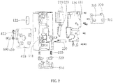
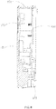
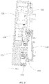
- the present invention provides a smart electronic lock, including a housing 100 that has an accommodating cavity 110, a lock cylinder assembly 200 disposed in the accommodating cavity 110, and two fastening assemblies.
- the housing 100 is enclosed by a front shell 120 and a rear shell 130.
- the two fastening assemblies are respectively correspondingly located at an upper portion and a lower portion of the back of the rear shell 130.
- the two fastening assemblies are respectively named an upper fastening assembly 300 and a lower fastening assembly 400.
- the upper portion of the rear shell 130 is correspondingly provided with a snap-fit structure 131 that snap-fits to the upper fastening assembly 300 in an upward/downward direction
- the lower portion of the rear shell 130 is correspondingly provided with a key assembly 500 that is fastened and locked to the lower fastening assembly 400 in an anterior/posterior direction.
- the lower fastening assembly 400 is fixedly connected to the housing 100.
- a panel 121 of the front shell 120 is provided with a sensor 122 for receiving an optical control signal, a circuit board assembly (not shown in the figures) for converting an optical signal received by the sensor 122 into an electrical signal is provided in the accommodating cavity 110, and the lock cylinder assembly 200 moves under control of the circuit board assembly, so that when the key assembly 500 is pressed, the lower fastening assembly 400 drives the key assembly 500 in an anterior/posterior direction to release a locking state between the lower fastening assembly 400 and the key assembly 500.
- the accommodating cavity 110 is located in the front shell 120 with an opening facing backward.
- the rear shell 130 is in a platy structure, and the platy structure of the rear shell 130 does not completely enclose the opening of the accommodating cavity 110.
- the lower portion of the rear shell 130 has a mounting hole 132 for mounting the key assembly 500. Unlocking is implemented by pressing the key assembly 500 upwards.
- the upper fastening assembly 300 and the lower fastening assembly 400 are respectively fastened to a case cover and a case body.
- the lower fastening assembly 400 is further fixedly connected to the housing 100.
- the upper fastening assembly 300 on the case cover is configured to preliminarily snap-fit to the snap-fit structure 131 of the housing 100
- the lower fastening assembly 400 on the case body and the key assembly 500 are configured to lock the housing 100 to the case body, that is, to further ensure that the upper fastening assembly 300 on the case cover does not fall off from the snap-fit structure 131 of the housing 100, thereby ultimately locking the case cover and the case body securely.
- the snap-fit structure 131 and the upper fastening assembly 300 can be easily opened after being released from the enhanced locking.
- the upper fastening assembly 300 is unlocked from the snap-fit structure 131 of the housing 100, so that the case cover and the case body have no restraint therebetween and are in an open state.
- the senor 122 in the present invention receives an optical signal from a camera flash of a mobile phone, where the camera flash of the mobile phone sends, by emitting light a blinking manner under control of mobile APP software, an optical signal that carries an unlocking signal.
- a fitting structure between the snap-fit structure 131 and the upper fastening assembly 300 may be alternatively disposed at a lower portion of the housing 100, and a fitting structure between the key assembly 500 and the lower fastening assembly 400 is disposed at an upper portion of the housing 100. After the locations are exchanged, unlocking is implemented by pressing the key assembly 500 downwards.
- the smart electronic lock according to this embodiment can be manually locked freely, and is unlocked by means of optical control by using a mobile APP, facilitating ease of use for a user and avoiding the problem that the password is forgotten because the lock has not been used for a long time.
- the lock cylinder assembly 200 is mounted inside a lock body, preventing the lock from being illegally unlocked by using other methods and featuring optimal security. This type of optical control facilitated unlocking method is novel and original, bringing completely new experience to users.
- the lock cylinder assembly 200 is controlled by using a circuit. Therefore, other functions may be added by using the circuit, for example, loading a GPS positioning function or a weak current reminder function, to further enhance operational performance of the smart electronic lock.
- the smart electronic lock mainly includes the following constituent parts: the lock cylinder assembly 200, the key assembly 500, the upper fastening assembly 300, and the lower fastening assembly 400.
- the lock cylinder assembly 200 the key assembly 500, the upper fastening assembly 300, and the lower fastening assembly 400.
- the lock cylinder assembly 200 is disposed in the accommodating cavity 110 and is mainly configured to implement locking and unlocking of the electronic lock.
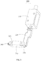
- the lock cylinder assembly 200 includes a vertically disposed electromagnet 210, a vertical pushrod 220 disposed at the bottom of the electromagnet 210, a horizontal pushrod 230 disposed at the bottom of the vertical pushrod 220, and a first elastic piece 240.
- One terminal of the horizontal pushrod 230 abuts against the bottom of the vertical pushrod 220 by using an inclined plane 250, and the first elastic piece 240 is disposed at the other terminal of the horizontal pushrod 230 for the horizontal pushrod 230 to return to position.
- the electromagnet 210 moves downwards and exerts downward thrust force on the vertical pushrod 220. Because the vertical pushrod 220 and the horizontal pushrod 230 abut against each other by using the inclined plane 250, when the vertical pushrod 220 moves downwards, the horizontal pushrod 230 is pushed by using the inclined plane 250 to move in a horizontal direction and compresses the first elastic piece 240. After power supply to the electromagnet 210 is interrupted, the thrust force from the electromagnet 210 on the vertical pushrod 220 is removed, the first elastic piece 240 returns to position and drives the horizontal pushrod 230 to move horizontally, and the vertical pushrod 220 is pushed by using the inclined plane 250 again to move upwards.
- the key assembly 500 is located beneath the horizontal pushrod 230.
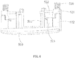
- the key assembly 500 includes a key 510, a push component 520 that is located on an inner side of the key 510 and that moves when pushed by the key 510, and a second elastic piece 530 disposed on the push component 520.
- Two inner pushrods 511 that protrude inwardly in parallel are disposed on the inner side of the key 510, outer sides of the two inner pushrods 511 are further separately provided with an ejector pin 512.
- the push component 520 includes a horizontally disposed connecting portion 521 and clamping portion 522.
- the connecting portion 521 correspondingly aligns with the ejector pin 512, and the clamping portion 522 is located between the ejector pin 512 and the inner pushrod 511. Because there is a gap 513 between the ejector pin 512 and the inner pushrod 511, the clamping portion 522 is located at the gap 513.
- an edge that is of the clamping portion 522 of each push component 520 and that faces the lower fastening assembly 400 protrudes downwards to form a first hook 523, and a clamping structure in the lower fastening assembly 400 extends into the gap 513 and clamps onto the first hook 523.
- a stepwise first fitting surface 524 is provided on the connecting portion 521 on a surface towards the key 510, a stepwise second fitting surface 525 is provided on each of the two ejector pins 512 on a surface towards the push component 520, and steps of the first fitting surface 524 and steps of the second fitting surface 525 engage in a staggered manner.
- the key 510 and the push component 520 are two independent parts. Therefore, setting of this type of stepwise fitting surface structures can ensure that the key 510 can accurately push the push component 520 when being moved.
- a first fastening post 526 is disposed on the connecting portion 521 on a surface away from the key 510.
- the second elastic piece 530 is a spring. One terminal of the spring is sleeved on the first fastening post 526, and with reference to FIG. 11 , the other terminal of the spring abuts against a second fastening post 112 in the accommodating cavity 110.
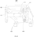
- the lower fastening assembly 400 that is fastened and locked to the key assembly 500 includes a fastening plate 410, and an actuator 420 and a torsional spring 430 that are disposed rotationally on an inner side of the fastening plate 410.
- Two second hooks 411 that can clamp onto the two first hooks 523 are extended from the interior bottom of the fastening plate 410.
- Two mounting portions 412 are disposed opposite to each other on the interior top of the fastening plate 410.
- the actuator 420 includes a rotating shaft 421 and two supporting arms 422 that are disposed opposite to each other. The rotating shaft 421 is placed horizontally, and two terminal parts of the rotating shaft 421 are respectively fastened to the two mounting portions 412.
- the two supporting arms 422 are placed obliquely. Top terminals of the two supporting arms 422 are respectively fastened to the two terminals of the rotating shaft 421, and bottom terminals of the two supporting arms 422 are separately fastened to the housing 100. Specifically, two mounting plates 111 that protrude from an outer side of the rear shell 130 are disposed in the accommodating cavity 110, and the bottom terminals of the two supporting arms 422 are respectively connected to the two mounting plates 111 fixedly by using a steady pin 600.
- the torsional spring 430 is sleeved on the rotating shaft 421, one terminal of the torsional spring 430 abuts against the inner side of the fastening plate 410, and the other terminal of the torsional spring 430 abuts against the rear shell 130.
- the snap-fit structure 131 on the rear shell 130 is two clamping grooves disposed on the rear shell 130, and openings of the two clamping grooves face downwards.
- the upper fastening assembly 300 includes a fastener 310 and two protrusions 320 that are disposed on the fastener 310, and the two protrusions 320 protrude upwards.
- an opening direction of the clamping groove is correspondingly adjusted to facing upwards
- orientations of the two protrusions 320 on the fastener 310 are correspondingly adjusted to facing downwards.
- a mounting hole 311 is disposed on the fastener 310.
- the sensor 122 disposed on the panel 121 of the front shell 120 is a sensing lens and can receive light emitted by a mobile APP.
- the housing 100 is pressed downwards, so that the two clamping grooves on the rear shell 130 snap-fit to the two protrusions 320 on the upper fastening assembly 300, to implement preliminary snap-fitting between the housing 100 and the case cover. Then, a lower portion of the housing 100 is pressed inwardly, so that the second hooks 411 on the lower fastening assembly 400 that is corresponding to the lower portion of the housing 100 moves forwards under the action of pressure to extend into the gap 513 in the key 510 and abut against the push component 520 along a fitting surface between the second hook 411 and the first hook 523.
- the second elastic piece 530 is pressed, making the second hook 411 slide into an inner side of the first hook 523 and clamp onto the first hook 523 reversely.
- the second elastic piece 530 bounces back and presses downwards against the push component 520. This ensures that the first hook 523 is securely clamped onto the second hook 411.
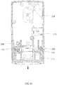
- the two terminals of the torsional spring 430 of the lower fastening assembly 400 respectively press against an inner side of the fastener 410 and the rear shell 130. So far, the smart electronic lock has been locked. Referring to FIG. 10 , in this process, the horizontal pushrod 230 and the first elastic piece 240 in the lock cylinder assembly 200 remain at original locations because they are free of exogenic action.
- a clearance slot 231 is disposed on the horizontal pushrod 230.
- the clearance slot 231 and a terminal portion of the inner pushrod 511 on the key 510 are staggered, and the terminal portion of the inner pushrod 511 abuts against the horizontal pushrod 230, so that the electronic lock cannot be opened.
- a mobile APP or a dedicated optical key is used to emit light to send an optical signal to the sensor 122, and the circuit board assembly is used to convert the optical signal into an electrical signal.
- the electromagnet 210 of the lock cylinder assembly 200 moves downwards and drives the vertical pushrod 220 to move downwards.
- the horizontal pushrod 230 moves horizontally when pushed by the vertical pushrod 220, and compresses the first elastic piece 240.
- the clearance slot 231 on the horizontal pushrod 230 moves to a location corresponding to that of the inner pushrod 511, the horizontal pushrod 230 stops moving.
- the key assembly 500 is pressed upwards, and the key 510 drives the push component 520 and the second elastic piece 530 to move upwards.
- the inner pushrod 511 in the key 510 extends inwardly into the clearance slot 231. This ensures that the key 510 has a sufficient distance to push the push component 520.
- the housing 100 is pulled upwards, so that the clamping groove on the top of the rear shell 130 is separated from the protrusion 320 on the upper fastening assembly 300, thereby completely separating the housing 100 from the upper fastening assembly 300 and implementing unlocking between the case cover and the case body.
- the present invention further provides a suitcase, including a case body and a case cover, where the foregoing smart electronic lock is disposed between the case body and the case cover.
- the upper fastening assembly 300 of the smart electronic lock is fastened to an edge of the case cover
- the lower fastening assembly 400 is fastened to an edge of a case body.
- the housing 100 and various internal parts are fixedly connected to the lower fastening assembly 400.
- the foregoing smart electronic lock is disposed. Therefore, a user can implement unlocking conveniently and rapidly by using a mobile APP, avoiding the problem that the password is forgotten because the lock has not been used for a long time.
- the lock cylinder assembly 200 is mounted inside a lock body, preventing the lock from being illegally unlocked by using other methods and featuring optimal security. This type of optical control facilitated unlocking method is novel and original, bringing completely new experience to users. Furthermore, the lock cylinder assembly 200 is controlled by using a circuit. Therefore, other functions may be added by using the circuit, for example, loading a GPS positioning function or a weak current reminder function, to further enhance operational performance of the suitcase.
Landscapes
- Physics & Mathematics (AREA)
- Electromagnetism (AREA)
- General Physics & Mathematics (AREA)
- Purses, Travelling Bags, Baskets, Or Suitcases (AREA)
- Telephone Set Structure (AREA)
- Casings For Electric Apparatus (AREA)
- Lock And Its Accessories (AREA)
Claims (10)
- Intelligentes elektronisches Schloss, umfassend ein Gehäuse (100), das von einer vorderen Schale (120) und einer hinteren Schale (130) umschlossen ist und das einen Aufnahmehohlraum (110), eine in dem Aufnahmehohlraum (110) angeordnete Schließzylinderanordnung (200) und zwei Befestigungsanordnungen (300, 400) aufweist, wobei die zwei Befestigungsanordnungen (300, 400) jeweils entsprechend an einem oberen Abschnitt und einem unteren Abschnitt der Rückseite der hinteren Schale (130) angeordnet sind, wobei das Gehäuse (100) mit einer Einraststruktur (131) versehen ist, die an einer der Befestigungsanordnungen (300) in einer Aufwärts-/Abwärtsrichtung einrastet, wobei das Gehäuse (100) mit einer Schlüsselanordnung (500) versehen ist, die an der anderen Befestigungsanordnung (400) in einer Vorwärts-/Rückwärtsrichtung befestigt und verriegelt wird, wobei die Befestigungsanordnung (400), die an der Schlüsselanordnung (500) befestigt und verriegelt ist, mit dem Gehäuse (100) fest verbunden ist, wobei eine Platte der Frontschale (120) mit einem Sensor (122) zum Empfangen eines optischen Steuersignals versehen ist, wobei eine Leiterplattenanordnung zum Umwandeln eines von dem Sensor (122) empfangenen optischen Signals in ein elektrisches Signal in dem Aufnahmehohlraum (110) vorgesehen ist und die Schließzylinderanordnung (200) sich gesteuert durch die Leiterplattenanordnung bewegt, so dass, wenn die Schlüsselanordnung (500) gedrückt wird, die andere Befestigungsanordnung (400) die Schlüsselanordnung (500) in einer Vorwärts-/Rückwärtsrichtung antreibt, um sich von der anderen Befestigungsanordnung zu lösen.
- Intelligentes elektronisches Schloss nach Anspruch 1, wobei die Schließzylinderanordnung (200) einen vertikal angeordneten Elektromagneten (210), eine vertikale Schubstange (220), die an der Oberseite oder Unterseite des Elektromagneten (210) angeordnet ist und die sich in einer Aufwärts-/Abwärtsrichtung bewegen kann, wenn sie durch den Elektromagneten (210) geschoben wird, eine horizontale Schubstange (230), die an der Oberseite oder Unterseite der vertikalen Schubstange (220) angeordnet ist, und ein erstes elastisches Teil (240) umfasst, wobei ein Anschluss der horizontalen Schubstange (230) an einem oberen Anschluss oder einem unteren Anschluss der vertikalen Schubstange (220) unter Verwendung einer schiefen Ebene anliegt und das erste elastische Teil (240) an dem anderen Anschluss der horizontalen Schubstange (230) angeordnet ist, um die horizontale Schubstange (230) in eine Position zurückzuführen.
- Intelligentes elektronisches Schloss nach Anspruch 2, wobei die Schlüsselanordnung (500) einen Schlüssel (510), eine Schubkomponente (520), die an einer Innenseite des Schlüssels (510) angeordnet ist und sich bewegt, wenn sie durch den Schlüssel (510) gedrückt wird, und ein zweites elastisches Teil (5300) umfasst, das an der Schubkomponente (520) angeordnet ist und an dem Inneren des Aufnahmehohlraums (110) anliegt, wobei an der Schubkomponente (520) ein erster Haken (523) angeordnet ist, an der Innenseite des Schlüssels (510) eine nach innen vorstehende innere Schubstange (511) angeordnet ist und an der horizontalen Schubstange (230) ein Freiraumschlitz (231) angeordnet ist; wobei in einem verriegelten Zustand der erste Haken (523) an der Schubkomponente (520) an einer der Befestigungsanordnungen befestigt und verriegelt ist und ein Anschlussabschnitt der inneren Schubstange (511) an der horizontalen Schubstange (230) anliegt und wobei während des Entriegelns, sich die horizontale Schubstange (230) unter einer Wirkung der vertikalen Schubstange (220) bewegt und wenn der Schlüssel (510) gedrückt wird, sich der Endabschnitt der inneren Schubstange (511) in den Freiraumschlitz (231) erstreckt und der Schlüssel (510) die Schubkomponente (520) antreibt, sich zu bewegen, so dass der erste Haken (523) von der Befestigungsanordnung (400) getrennt wird.
- Intelligentes elektronisches Schloss nach Anspruch 3, wobei es zwei innere Schubstangen (511) gibt, wobei die zwei inneren Schubstangen (511) parallel auf der Innenseite des Schlüssels (510) angeordnet sind, wobei zwei Auswerferstifte (512) ebenfalls auf der Innenseite des Schlüssels (510) angeordnet sind, wobei die zwei Auswerferstifte (511) jeweils auf Außenseiten der zwei inneren Schubstangen (511) angeordnet sind und es zwei Schubkomponenten (520) gibt, die jeweils auf den Innenseiten der zwei Auswerferstifte (512) angeordnet sind.
- Intelligentes elektronisches Schloss nach Anspruch 4, wobei eine stufenweise erste Passfläche (524) auf jeder der beiden Schubkomponenten (520) auf einer Fläche in Richtung des Schlüssels (510) vorgesehen ist, wobei eine stufenweise zweite Passfläche (525) auf jedem der beiden Auswerferstifte (512) auf einer Fläche in Richtung der Schubkomponente (520) vorgesehen ist und Stufen der ersten Passfläche (524) und Stufen der zweiten Passfläche (525) versetzt ineinandergreifen.
- Intelligentes elektronisches Schloss nach einem der Ansprüche 1 bis 5, wobei die Befestigungsanordnung (400), die an der Schlüsselanordnung (500) befestigt und verriegelt ist, eine Befestigungsplatte (410) und einen Aktuator (420) und eine Torsionsfeder (430) umfasst, die drehbar an einer Innenseite der Befestigungsplatte (410) angeordnet sind, wobei der Anschluss der Befestigungsplatte (410), der von der Befestigungsplatte (410) abgewandt ist, an dem Gehäuse (100) befestigt ist und wobei auf der Innenseite der Befestigungsplatte (410) ein zweiter Haken (411) angeordnet ist, der an der Schlüsselanordnung (500) einrastet.
- Intelligentes elektronisches Schloss nach Anspruch 6, wobei der Aktuator (420) eine Drehwelle (421), die an der Innenseite der Befestigungsplatte (410) horizontal befestigt ist, und zwei Tragarme (422), die einander gegenüberliegend angeordnet sind, umfasst, wobei die oberen Anschlüsse der beiden Tragarme (422) jeweils an zwei Anschlüssen der Drehwelle (421) befestigt sind, wobei die unteren Anschlüsse der beiden Tragarme (422) an dem Gehäuse (100) separat befestigt sind, wobei die Torsionsfeder (430) auf der Drehwelle (421) aufgesteckt ist, wobei ein Anschluss der Torsionsfeder (430) an der Innenseite der Befestigungsplatte (410) anliegt und der andere Anschluss der Torsionsfeder (430) an der hinteren Schale (130) anliegt.
- Intelligentes elektronisches Schloss nach Anspruch 6, wobei zwei Montageplatten (111), die von einer Außenseite der hinteren Schale (130) vorstehen, in dem Aufnahmehohlraum (110) angeordnet sind und die zwei Tragarme (422) jeweils mit den zwei Montageplatten (111) durch Verwendung eines festen Stiftes (600) fest verbunden sind.
- Intelligentes elektronisches Schloss nach Anspruch 1, wobei die Einraststruktur (131) aus zwei Klemmnuten besteht, die in der hinteren Schale (130) angeordnet sind, und die Befestigungsanordnung (300), die an der Einraststruktur (131) einrastet, ein Befestigungselement (310) und zwei Vorsprünge (320) umfasst, die an dem Befestigungselement (310) angeordnet sind und die in die beiden Klemmnuten in einer Aufwärts-/Abwärtsrichtung eingeführt sind.
- Koffer, umfassend einen Kofferkörper und einen Kofferdeckel, wobei das intelligente elektronische Schloss nach einem der Ansprüche 1 bis 9 zwischen dem Kofferkörper und dem Kofferdeckel angeordnet ist.
Applications Claiming Priority (3)
| Application Number | Priority Date | Filing Date | Title |
|---|---|---|---|
| CN201620758700.1U CN205947325U (zh) | 2016-07-19 | 2016-07-19 | 一种节能光子旅行箱及其电源电路 |
| CN201610569630.XA CN107630601B (zh) | 2016-07-19 | 2016-07-19 | 智能电子锁及旅行箱 |
| PCT/CN2017/092068 WO2018014739A1 (zh) | 2016-07-19 | 2017-07-06 | 智能电子锁及旅行箱 |
Publications (3)
| Publication Number | Publication Date |
|---|---|
| EP3489440A1 EP3489440A1 (de) | 2019-05-29 |
| EP3489440A4 EP3489440A4 (de) | 2020-04-15 |
| EP3489440B1 true EP3489440B1 (de) | 2021-06-23 |
Family
ID=60991984
Family Applications (1)
| Application Number | Title | Priority Date | Filing Date |
|---|---|---|---|
| EP17830373.1A Active EP3489440B1 (de) | 2016-07-19 | 2017-07-06 | Intelligentes, elektronisches schloss und koffer |
Country Status (5)
| Country | Link |
|---|---|
| US (1) | US11299915B2 (de) |
| EP (1) | EP3489440B1 (de) |
| JP (1) | JP6854338B2 (de) |
| KR (1) | KR102128930B1 (de) |
| WO (1) | WO2018014739A1 (de) |
Families Citing this family (3)
| Publication number | Priority date | Publication date | Assignee | Title |
|---|---|---|---|---|
| KR102086475B1 (ko) | 2019-09-10 | 2020-03-09 | 박정원 | 생체정보를 이용한 잠금장치 |
| CN212802875U (zh) * | 2020-06-02 | 2021-03-26 | 杭州丝途网络科技有限公司 | 电磁锁 |
| CN111734229B (zh) * | 2020-06-16 | 2025-09-09 | 广州国保科技有限公司 | 一种电子锁 |
Family Cites Families (24)
| Publication number | Priority date | Publication date | Assignee | Title |
|---|---|---|---|---|
| US4372590A (en) * | 1979-04-10 | 1983-02-08 | Pilat Eugene R | Electronic security device and method |
| CN2132808Y (zh) * | 1992-08-27 | 1993-05-12 | 古明弘 | 提箱锁 |
| CN2165195Y (zh) * | 1993-08-20 | 1994-05-18 | 江枝昌 | 一种手提箱锁具 |
| JPH08189240A (ja) | 1995-01-11 | 1996-07-23 | Hinomoto Jomae:Kk | かばん錠 |
| JP3505671B2 (ja) * | 1996-01-08 | 2004-03-08 | 豊和化成株式会社 | 蓋体のロック機構 |
| JP3681660B2 (ja) | 2000-07-21 | 2005-08-10 | 容徳 新井 | 遠隔制御可能なドアロック装置 |
| JP2003293639A (ja) | 2002-01-30 | 2003-10-15 | Honki Han | 鞄 |
| KR100750315B1 (ko) | 2007-03-15 | 2007-08-17 | 조선웅 | 지문 인식이 부착된 멀티형 자동 잠금장치 |
| ES2384284T3 (es) * | 2008-07-02 | 2012-07-03 | Ojmar S.A. | Cerradura electrónica programable |
| CN202117425U (zh) * | 2011-04-27 | 2012-01-18 | 珠海天宏科技实业有限公司 | 电磁感应箱包锁 |
| US9187929B2 (en) * | 2011-09-18 | 2015-11-17 | Hanchett Entry Systems, Inc. | Electronic cabinet/drawer lock system |
| KR20140006513A (ko) * | 2012-07-06 | 2014-01-16 | 주식회사 아이디로 | 가시광 통신을 이용한 도어락 시스템 |
| KR101738792B1 (ko) * | 2012-08-13 | 2017-05-22 | 쿠앙-치 이노베이티브 테크놀로지 리미티드 | 광신호 처리장치 및 광신호 수신 모니터링장치 디코딩 방법 |
| JP2014120233A (ja) | 2012-12-13 | 2014-06-30 | Tokai Rika Co Ltd | ロック装置 |
| US9154486B1 (en) * | 2013-03-14 | 2015-10-06 | Microstrategy Incorporated | Securing luggage |
| CN204199894U (zh) | 2014-04-30 | 2015-03-11 | 金泰祥精密五金(昆山)有限公司 | 锁具及使用该锁具的箱体 |
| US9424722B2 (en) * | 2014-05-14 | 2016-08-23 | Unlimited Liability, LLC | Smart memory material lock devices |
| US20150348347A1 (en) | 2014-05-27 | 2015-12-03 | Bluesmart Inc. | Active container |
| CN204457136U (zh) * | 2014-11-27 | 2015-07-08 | 胥运怀 | 一种手机闪光灯控制门锁 |
| CN204492363U (zh) * | 2015-01-28 | 2015-07-22 | 无锡市天普精密五金制造有限公司 | 新型密码锁 |
| CN205778022U (zh) * | 2016-07-19 | 2016-12-07 | 深圳光启智能光子技术有限公司 | 智能电子锁及旅行箱 |
| JP6302587B1 (ja) * | 2017-04-05 | 2018-03-28 | 株式会社 ジェイビーエス | 鞄類のファスナーロック装置 |
| US10253528B1 (en) * | 2018-02-21 | 2019-04-09 | Axtuator OY | Digital lock |
| US10990356B2 (en) * | 2019-02-18 | 2021-04-27 | Quantum Lock Technologies LLC | Tamper-resistant smart factory |
-
2017
- 2017-07-06 EP EP17830373.1A patent/EP3489440B1/de active Active
- 2017-07-06 KR KR1020197004465A patent/KR102128930B1/ko not_active Expired - Fee Related
- 2017-07-06 US US16/319,253 patent/US11299915B2/en not_active Expired - Fee Related
- 2017-07-06 JP JP2019502748A patent/JP6854338B2/ja not_active Expired - Fee Related
- 2017-07-06 WO PCT/CN2017/092068 patent/WO2018014739A1/zh not_active Ceased
Also Published As
| Publication number | Publication date |
|---|---|
| US20190264469A1 (en) | 2019-08-29 |
| KR20190028522A (ko) | 2019-03-18 |
| JP6854338B2 (ja) | 2021-04-07 |
| EP3489440A1 (de) | 2019-05-29 |
| KR102128930B1 (ko) | 2020-07-01 |
| EP3489440A4 (de) | 2020-04-15 |
| US11299915B2 (en) | 2022-04-12 |
| WO2018014739A1 (zh) | 2018-01-25 |
| JP2019520947A (ja) | 2019-07-25 |
Similar Documents
| Publication | Publication Date | Title |
|---|---|---|
| KR100703475B1 (ko) | 휴대 단말기의 배터리팩 락킹 장치 | |
| US11299915B2 (en) | Smart electronic lock and suitcase | |
| CN106505167B (zh) | 电子设备及用于该电子设备的壳体锁持机构 | |
| CN110383524B (zh) | 电池模块以及无人机 | |
| CN112929473B (zh) | 电子设备 | |
| US9730351B2 (en) | Electrical connector assembly with holding member | |
| KR100640369B1 (ko) | 휴대 단말기의 내장형 배터리팩 케이스 락킹 장치 | |
| CN205792539U (zh) | 集成卡座组件及具有该集成卡座组件的移动终端 | |
| JP5609233B2 (ja) | 防水蓋装置、及び電子機器 | |
| CN107630601B (zh) | 智能电子锁及旅行箱 | |
| CN212781898U (zh) | 自锁机构、具有自锁机构与把手的配合结构及服务器 | |
| CN110284302B (zh) | 壳体组件及具有其的洗衣机 | |
| US20210343094A1 (en) | Combination lock and notebook using the same | |
| CN104314365A (zh) | 锁芯盖机构 | |
| CN212305419U (zh) | 电子产品保护壳 | |
| CN108487797B (zh) | 一种指纹锁结构及指纹锁笔记本 | |
| CN216974456U (zh) | 一种智能锁盒 | |
| CN212827481U (zh) | 一种印章 | |
| CN208024118U (zh) | 锁止装置及其门锁系统 | |
| CN209964459U (zh) | 一种自动开启后盖的终端设备 | |
| CN222145513U (zh) | 一种手持终端设备 | |
| CN217233106U (zh) | 一种电子锁组件 | |
| CN223880993U (zh) | 适于自动开门的智能储物柜 | |
| CN221031999U (zh) | 一种方便拆卸显示屏幕的智能门锁 | |
| CN209982102U (zh) | 一种移动电源 |
Legal Events
| Date | Code | Title | Description |
|---|---|---|---|
| STAA | Information on the status of an ep patent application or granted ep patent |
Free format text: STATUS: THE INTERNATIONAL PUBLICATION HAS BEEN MADE |
|
| PUAI | Public reference made under article 153(3) epc to a published international application that has entered the european phase |
Free format text: ORIGINAL CODE: 0009012 |
|
| STAA | Information on the status of an ep patent application or granted ep patent |
Free format text: STATUS: REQUEST FOR EXAMINATION WAS MADE |
|
| 17P | Request for examination filed |
Effective date: 20190215 |
|
| AK | Designated contracting states |
Kind code of ref document: A1 Designated state(s): AL AT BE BG CH CY CZ DE DK EE ES FI FR GB GR HR HU IE IS IT LI LT LU LV MC MK MT NL NO PL PT RO RS SE SI SK SM TR |
|
| AX | Request for extension of the european patent |
Extension state: BA ME |
|
| DAV | Request for validation of the european patent (deleted) | ||
| DAX | Request for extension of the european patent (deleted) | ||
| A4 | Supplementary search report drawn up and despatched |
Effective date: 20200316 |
|
| RIC1 | Information provided on ipc code assigned before grant |
Ipc: E05B 65/52 20060101AFI20200310BHEP Ipc: E05B 47/02 20060101ALI20200310BHEP Ipc: E05B 47/00 20060101ALN20200310BHEP |
|
| GRAP | Despatch of communication of intention to grant a patent |
Free format text: ORIGINAL CODE: EPIDOSNIGR1 |
|
| STAA | Information on the status of an ep patent application or granted ep patent |
Free format text: STATUS: GRANT OF PATENT IS INTENDED |
|
| RIC1 | Information provided on ipc code assigned before grant |
Ipc: E05B 47/02 20060101ALI20201230BHEP Ipc: E05B 65/52 20060101AFI20201230BHEP Ipc: E05B 47/00 20060101ALN20201230BHEP |
|
| INTG | Intention to grant announced |
Effective date: 20210126 |
|
| GRAS | Grant fee paid |
Free format text: ORIGINAL CODE: EPIDOSNIGR3 |
|
| GRAA | (expected) grant |
Free format text: ORIGINAL CODE: 0009210 |
|
| STAA | Information on the status of an ep patent application or granted ep patent |
Free format text: STATUS: THE PATENT HAS BEEN GRANTED |
|
| AK | Designated contracting states |
Kind code of ref document: B1 Designated state(s): AL AT BE BG CH CY CZ DE DK EE ES FI FR GB GR HR HU IE IS IT LI LT LU LV MC MK MT NL NO PL PT RO RS SE SI SK SM TR |
|
| REG | Reference to a national code |
Ref country code: GB Ref legal event code: FG4D |
|
| REG | Reference to a national code |
Ref country code: CH Ref legal event code: EP |
|
| REG | Reference to a national code |
Ref country code: DE Ref legal event code: R096 Ref document number: 602017040952 Country of ref document: DE Ref country code: AT Ref legal event code: REF Ref document number: 1404461 Country of ref document: AT Kind code of ref document: T Effective date: 20210715 |
|
| REG | Reference to a national code |
Ref country code: IE Ref legal event code: FG4D |
|
| REG | Reference to a national code |
Ref country code: LT Ref legal event code: MG9D |
|
| PG25 | Lapsed in a contracting state [announced via postgrant information from national office to epo] |
Ref country code: LT Free format text: LAPSE BECAUSE OF FAILURE TO SUBMIT A TRANSLATION OF THE DESCRIPTION OR TO PAY THE FEE WITHIN THE PRESCRIBED TIME-LIMIT Effective date: 20210623 Ref country code: FI Free format text: LAPSE BECAUSE OF FAILURE TO SUBMIT A TRANSLATION OF THE DESCRIPTION OR TO PAY THE FEE WITHIN THE PRESCRIBED TIME-LIMIT Effective date: 20210623 Ref country code: HR Free format text: LAPSE BECAUSE OF FAILURE TO SUBMIT A TRANSLATION OF THE DESCRIPTION OR TO PAY THE FEE WITHIN THE PRESCRIBED TIME-LIMIT Effective date: 20210623 Ref country code: BG Free format text: LAPSE BECAUSE OF FAILURE TO SUBMIT A TRANSLATION OF THE DESCRIPTION OR TO PAY THE FEE WITHIN THE PRESCRIBED TIME-LIMIT Effective date: 20210923 |
|
| REG | Reference to a national code |
Ref country code: AT Ref legal event code: MK05 Ref document number: 1404461 Country of ref document: AT Kind code of ref document: T Effective date: 20210623 |
|
| PG25 | Lapsed in a contracting state [announced via postgrant information from national office to epo] |
Ref country code: LV Free format text: LAPSE BECAUSE OF FAILURE TO SUBMIT A TRANSLATION OF THE DESCRIPTION OR TO PAY THE FEE WITHIN THE PRESCRIBED TIME-LIMIT Effective date: 20210623 Ref country code: NO Free format text: LAPSE BECAUSE OF FAILURE TO SUBMIT A TRANSLATION OF THE DESCRIPTION OR TO PAY THE FEE WITHIN THE PRESCRIBED TIME-LIMIT Effective date: 20210923 Ref country code: SE Free format text: LAPSE BECAUSE OF FAILURE TO SUBMIT A TRANSLATION OF THE DESCRIPTION OR TO PAY THE FEE WITHIN THE PRESCRIBED TIME-LIMIT Effective date: 20210623 Ref country code: RS Free format text: LAPSE BECAUSE OF FAILURE TO SUBMIT A TRANSLATION OF THE DESCRIPTION OR TO PAY THE FEE WITHIN THE PRESCRIBED TIME-LIMIT Effective date: 20210623 Ref country code: GR Free format text: LAPSE BECAUSE OF FAILURE TO SUBMIT A TRANSLATION OF THE DESCRIPTION OR TO PAY THE FEE WITHIN THE PRESCRIBED TIME-LIMIT Effective date: 20210924 |
|
| REG | Reference to a national code |
Ref country code: NL Ref legal event code: MP Effective date: 20210623 |
|
| PG25 | Lapsed in a contracting state [announced via postgrant information from national office to epo] |
Ref country code: SK Free format text: LAPSE BECAUSE OF FAILURE TO SUBMIT A TRANSLATION OF THE DESCRIPTION OR TO PAY THE FEE WITHIN THE PRESCRIBED TIME-LIMIT Effective date: 20210623 Ref country code: SM Free format text: LAPSE BECAUSE OF FAILURE TO SUBMIT A TRANSLATION OF THE DESCRIPTION OR TO PAY THE FEE WITHIN THE PRESCRIBED TIME-LIMIT Effective date: 20210623 Ref country code: ES Free format text: LAPSE BECAUSE OF FAILURE TO SUBMIT A TRANSLATION OF THE DESCRIPTION OR TO PAY THE FEE WITHIN THE PRESCRIBED TIME-LIMIT Effective date: 20210623 Ref country code: PT Free format text: LAPSE BECAUSE OF FAILURE TO SUBMIT A TRANSLATION OF THE DESCRIPTION OR TO PAY THE FEE WITHIN THE PRESCRIBED TIME-LIMIT Effective date: 20211025 Ref country code: NL Free format text: LAPSE BECAUSE OF FAILURE TO SUBMIT A TRANSLATION OF THE DESCRIPTION OR TO PAY THE FEE WITHIN THE PRESCRIBED TIME-LIMIT Effective date: 20210623 Ref country code: RO Free format text: LAPSE BECAUSE OF FAILURE TO SUBMIT A TRANSLATION OF THE DESCRIPTION OR TO PAY THE FEE WITHIN THE PRESCRIBED TIME-LIMIT Effective date: 20210623 Ref country code: AT Free format text: LAPSE BECAUSE OF FAILURE TO SUBMIT A TRANSLATION OF THE DESCRIPTION OR TO PAY THE FEE WITHIN THE PRESCRIBED TIME-LIMIT Effective date: 20210623 Ref country code: EE Free format text: LAPSE BECAUSE OF FAILURE TO SUBMIT A TRANSLATION OF THE DESCRIPTION OR TO PAY THE FEE WITHIN THE PRESCRIBED TIME-LIMIT Effective date: 20210623 Ref country code: CZ Free format text: LAPSE BECAUSE OF FAILURE TO SUBMIT A TRANSLATION OF THE DESCRIPTION OR TO PAY THE FEE WITHIN THE PRESCRIBED TIME-LIMIT Effective date: 20210623 |
|
| REG | Reference to a national code |
Ref country code: DE Ref legal event code: R119 Ref document number: 602017040952 Country of ref document: DE |
|
| PG25 | Lapsed in a contracting state [announced via postgrant information from national office to epo] |
Ref country code: PL Free format text: LAPSE BECAUSE OF FAILURE TO SUBMIT A TRANSLATION OF THE DESCRIPTION OR TO PAY THE FEE WITHIN THE PRESCRIBED TIME-LIMIT Effective date: 20210623 |
|
| REG | Reference to a national code |
Ref country code: CH Ref legal event code: PL |
|
| PG25 | Lapsed in a contracting state [announced via postgrant information from national office to epo] |
Ref country code: MC Free format text: LAPSE BECAUSE OF FAILURE TO SUBMIT A TRANSLATION OF THE DESCRIPTION OR TO PAY THE FEE WITHIN THE PRESCRIBED TIME-LIMIT Effective date: 20210623 |
|
| REG | Reference to a national code |
Ref country code: BE Ref legal event code: MM Effective date: 20210731 |
|
| PG25 | Lapsed in a contracting state [announced via postgrant information from national office to epo] |
Ref country code: LI Free format text: LAPSE BECAUSE OF NON-PAYMENT OF DUE FEES Effective date: 20210731 Ref country code: DK Free format text: LAPSE BECAUSE OF FAILURE TO SUBMIT A TRANSLATION OF THE DESCRIPTION OR TO PAY THE FEE WITHIN THE PRESCRIBED TIME-LIMIT Effective date: 20210623 Ref country code: DE Free format text: LAPSE BECAUSE OF NON-PAYMENT OF DUE FEES Effective date: 20220201 Ref country code: CH Free format text: LAPSE BECAUSE OF NON-PAYMENT OF DUE FEES Effective date: 20210731 |
|
| PLBE | No opposition filed within time limit |
Free format text: ORIGINAL CODE: 0009261 |
|
| STAA | Information on the status of an ep patent application or granted ep patent |
Free format text: STATUS: NO OPPOSITION FILED WITHIN TIME LIMIT |
|
| GBPC | Gb: european patent ceased through non-payment of renewal fee |
Effective date: 20210923 |
|
| 26N | No opposition filed |
Effective date: 20220324 |
|
| PG25 | Lapsed in a contracting state [announced via postgrant information from national office to epo] |
Ref country code: LU Free format text: LAPSE BECAUSE OF NON-PAYMENT OF DUE FEES Effective date: 20210706 Ref country code: AL Free format text: LAPSE BECAUSE OF FAILURE TO SUBMIT A TRANSLATION OF THE DESCRIPTION OR TO PAY THE FEE WITHIN THE PRESCRIBED TIME-LIMIT Effective date: 20210623 |
|
| PG25 | Lapsed in a contracting state [announced via postgrant information from national office to epo] |
Ref country code: IT Free format text: LAPSE BECAUSE OF FAILURE TO SUBMIT A TRANSLATION OF THE DESCRIPTION OR TO PAY THE FEE WITHIN THE PRESCRIBED TIME-LIMIT Effective date: 20210623 Ref country code: IE Free format text: LAPSE BECAUSE OF NON-PAYMENT OF DUE FEES Effective date: 20210706 Ref country code: GB Free format text: LAPSE BECAUSE OF NON-PAYMENT OF DUE FEES Effective date: 20210923 Ref country code: FR Free format text: LAPSE BECAUSE OF NON-PAYMENT OF DUE FEES Effective date: 20210823 Ref country code: BE Free format text: LAPSE BECAUSE OF NON-PAYMENT OF DUE FEES Effective date: 20210731 |
|
| PG25 | Lapsed in a contracting state [announced via postgrant information from national office to epo] |
Ref country code: CY Free format text: LAPSE BECAUSE OF FAILURE TO SUBMIT A TRANSLATION OF THE DESCRIPTION OR TO PAY THE FEE WITHIN THE PRESCRIBED TIME-LIMIT Effective date: 20210623 |
|
| PG25 | Lapsed in a contracting state [announced via postgrant information from national office to epo] |
Ref country code: HU Free format text: LAPSE BECAUSE OF FAILURE TO SUBMIT A TRANSLATION OF THE DESCRIPTION OR TO PAY THE FEE WITHIN THE PRESCRIBED TIME-LIMIT; INVALID AB INITIO Effective date: 20170706 |
|
| PG25 | Lapsed in a contracting state [announced via postgrant information from national office to epo] |
Ref country code: MK Free format text: LAPSE BECAUSE OF FAILURE TO SUBMIT A TRANSLATION OF THE DESCRIPTION OR TO PAY THE FEE WITHIN THE PRESCRIBED TIME-LIMIT Effective date: 20210623 |
|
| PG25 | Lapsed in a contracting state [announced via postgrant information from national office to epo] |
Ref country code: MT Free format text: LAPSE BECAUSE OF FAILURE TO SUBMIT A TRANSLATION OF THE DESCRIPTION OR TO PAY THE FEE WITHIN THE PRESCRIBED TIME-LIMIT Effective date: 20210623 |
|
| PG25 | Lapsed in a contracting state [announced via postgrant information from national office to epo] |
Ref country code: TR Free format text: LAPSE BECAUSE OF FAILURE TO SUBMIT A TRANSLATION OF THE DESCRIPTION OR TO PAY THE FEE WITHIN THE PRESCRIBED TIME-LIMIT Effective date: 20210623 |