EP3489140B1 - Aircraft system with asisted taxi, take off, and climbing - Google Patents
Aircraft system with asisted taxi, take off, and climbing Download PDFInfo
- Publication number
- EP3489140B1 EP3489140B1 EP17382801.3A EP17382801A EP3489140B1 EP 3489140 B1 EP3489140 B1 EP 3489140B1 EP 17382801 A EP17382801 A EP 17382801A EP 3489140 B1 EP3489140 B1 EP 3489140B1
- Authority
- EP
- European Patent Office
- Prior art keywords
- air vehicle
- main
- auxiliary air
- vehicle
- main air
- Prior art date
- Legal status (The legal status is an assumption and is not a legal conclusion. Google has not performed a legal analysis and makes no representation as to the accuracy of the status listed.)
- Active
Links
- 230000009194 climbing Effects 0.000 title claims description 13
- 239000000446 fuel Substances 0.000 claims description 16
- 210000001015 abdomen Anatomy 0.000 claims description 5
- 238000004146 energy storage Methods 0.000 claims 1
- 238000010248 power generation Methods 0.000 claims 1
- 239000002828 fuel tank Substances 0.000 description 5
- 238000004519 manufacturing process Methods 0.000 description 5
- 238000003032 molecular docking Methods 0.000 description 3
- 238000004513 sizing Methods 0.000 description 3
- 230000008901 benefit Effects 0.000 description 2
- 230000005611 electricity Effects 0.000 description 2
- 238000012986 modification Methods 0.000 description 2
- 230000004048 modification Effects 0.000 description 2
- 238000005457 optimization Methods 0.000 description 2
- 239000002131 composite material Substances 0.000 description 1
- 230000000694 effects Effects 0.000 description 1
- 239000011888 foil Substances 0.000 description 1
- 230000005484 gravity Effects 0.000 description 1
- 238000000034 method Methods 0.000 description 1
- 238000000926 separation method Methods 0.000 description 1
- 239000003381 stabilizer Substances 0.000 description 1
Images


Classifications
-
- B—PERFORMING OPERATIONS; TRANSPORTING
- B64—AIRCRAFT; AVIATION; COSMONAUTICS
- B64F—GROUND OR AIRCRAFT-CARRIER-DECK INSTALLATIONS SPECIALLY ADAPTED FOR USE IN CONNECTION WITH AIRCRAFT; DESIGNING, MANUFACTURING, ASSEMBLING, CLEANING, MAINTAINING OR REPAIRING AIRCRAFT, NOT OTHERWISE PROVIDED FOR; HANDLING, TRANSPORTING, TESTING OR INSPECTING AIRCRAFT COMPONENTS, NOT OTHERWISE PROVIDED FOR
- B64F1/00—Ground or aircraft-carrier-deck installations
- B64F1/04—Launching or towing gear
- B64F1/10—Launching or towing gear using self-propelled vehicles
-
- B—PERFORMING OPERATIONS; TRANSPORTING
- B64—AIRCRAFT; AVIATION; COSMONAUTICS
- B64D—EQUIPMENT FOR FITTING IN OR TO AIRCRAFT; FLIGHT SUITS; PARACHUTES; ARRANGEMENTS OR MOUNTING OF POWER PLANTS OR PROPULSION TRANSMISSIONS IN AIRCRAFT
- B64D5/00—Aircraft transported by aircraft, e.g. for release or reberthing during flight
-
- B—PERFORMING OPERATIONS; TRANSPORTING
- B64—AIRCRAFT; AVIATION; COSMONAUTICS
- B64C—AEROPLANES; HELICOPTERS
- B64C25/00—Alighting gear
- B64C25/02—Undercarriages
- B64C25/08—Undercarriages non-fixed, e.g. jettisonable
-
- B—PERFORMING OPERATIONS; TRANSPORTING
- B64—AIRCRAFT; AVIATION; COSMONAUTICS
- B64F—GROUND OR AIRCRAFT-CARRIER-DECK INSTALLATIONS SPECIALLY ADAPTED FOR USE IN CONNECTION WITH AIRCRAFT; DESIGNING, MANUFACTURING, ASSEMBLING, CLEANING, MAINTAINING OR REPAIRING AIRCRAFT, NOT OTHERWISE PROVIDED FOR; HANDLING, TRANSPORTING, TESTING OR INSPECTING AIRCRAFT COMPONENTS, NOT OTHERWISE PROVIDED FOR
- B64F1/00—Ground or aircraft-carrier-deck installations
- B64F1/22—Ground or aircraft-carrier-deck installations installed for handling aircraft
- B64F1/225—Towing trucks
- B64F1/227—Towing trucks adapted for directly connecting to aircraft, e.g. trucks without tow-bars
Definitions
- the invention relates to the technical fields of: overall aircraft design, airframe concepts, and civil and military aircraft operations.
- a general object of the invention is to reduce costs associated to aircraft operations and aircraft production. By optimizing the design (sizing) and capabilities of some systems of an aircraft, in accordance to what is really required from those systems to complete a flight, a more efficient aircraft is obtained.
- a more specific object of the invention is to reduce aircraft weight, thereby reducing fuel consumption and extending mission range.
- the airframe perform in an autonomous manner, that is, without support from external equipments, all the phases of a complete revenue flight, namely: ground operation, push back, taxi out, take off, climbing, cruise, descend, landing and taxi to gate.
- all aircraft systems and features like aerodynamic and structure are designed to perform all phases of a flight.
- external fuel tanks have been used for decades to increase mission ranges in military aircraft, or as initial rocket stages in space vehicles, or for Short Take-off and Landing (STOL) operations of conventional aircraft.
- STOL Short Take-off and Landing
- British patents GB-0.429.948 and GB-0.525.015 are prior art examples disclosing the use of an auxiliary air vehicle for the assistance of a main air vehicle during take-off.
- Main and auxiliary air vehicles are mounted one on top of the other during take-off, such as once take-off is completed they are separated and fly independently.
- US patent application US2981499A relates to an aerial catapult for assisting the take-off and climb of an aircraft and method of launching thereby.
- US patent US8925857B2 relates to an in-line staged aircraft comprising a launch vehicle and a flight vehicle which are configured to join together along a common center line and form a single air foil in the joined configuration, wherein the flight vehicle and the launch vehicle are separable in flight.
- EP0581513 A1 describes a composite aircraft comprising a conventional aircraft (2) and a carrier aircraft (4) connected together by way of a connector (6), the carrier aircraft having a vertical takeoff and/or landing capability such that it may assist the conventional aircraft in taking-off and landing vertically.
- the present invention significantly reduces fuel cost associated to aircraft operations and aircraft production, by disaggregating some aircraft systems in two air vehicles, each one of them optimized for different phases of a flight.
- the aircraft system according to the invention comprises two air vehicles detachably connectable to each other, namely:
- Both air vehicles are coupled together during the initial stages of a flight mission, that is, taxi-out, take-off and climbing, and during these phases, both air vehicles are controlled from the main air vehicle.
- the auxiliary air vehicle is detached from the main air vehicle, as its equipments and systems are no longer necessary for the rest of the flight.
- the auxiliary air vehicle After detachment, the auxiliary air vehicle flies back to the airport of origin (or other), either in an automatic or remote unmanned operation, and the main air vehicle complete normally the rest of the flight to destination carrying out on its own, cruise, descend, landing and taxing to gate phases.
- an aspect of the invention refers to an aircraft system with assisted take-off and climbing, comprising: a main air
- the aircraft system further comprises an auxiliary air vehicle which is lighter than the main air vehicle, and it is adapted to assist (cooperate with) the main air vehicle during the ground operations, taxing, take-off and climbing phases of a flight.
- the main and auxiliary air vehicles are adapted to be detachably connectable, so that the auxiliary air vehicle assists the main air vehicle when both are attached to each other.
- the auxiliary air vehicle is detachably connectable to the belly of the main air vehicle. This configuration is considered optimum to ease ground maneuvering and docking of this auxiliary vehicle to the main air vehicle without external aids. This configuration also allows that the Center of Gravity of both vehicles is close enough to ensure the proper flight handling capabilities of both vehicles while they are attached together.
- the auxiliary air vehicle is provided with its own landing gear, such as when the main and auxiliary air vehicles are attached during taxing and take-off, the landing gear of both air vehicles are extended and on the ground, and in such a way that the auxiliary air vehicle partially supports the weight of the main air vehicle.
- the auxiliary air vehicle is arranged between the left and right (port and starboard) main landing gears of the main air vehicle.
- a technical effect derived from this arrangement is that aircraft airframe and landing gear of the main air vehicle, can be downsized. Additionally, the power plant of the main air vehicle is downsized, as the thrust of the powerplant of the auxiliary air vehicle is added.
- the main dimensioning factor of the engines thrust is the capability of taking-off with only one engine at maximum power once that the decision speed (also known as V1) is reached and kept after take-off a minimum climb rate to avoid ground obstacles. Therefore, adding the additional thrust of the auxiliary air vehicle, enables that thrust reduction of the power plant of the main aircraft.
- the aircraft system of the invention reduces the overall production and operation costs by downsizing equipments and optimizing the design of the main aircraft and reducing fuel burn, which in turn allow to:
- the auxiliary air vehicle can be designed for:
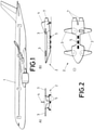
- the aircraft system of the invention comprises a main air vehicle (1) with a very similar appearance of a conventional commercial aircraft, that is capable of carrying a payload, in this example passengers and cargo.
- the main air vehicle (1) has an optimized airframe to carry out autonomously the cruise, descend and landing phases of a flight.
- This optimization involves:
- Figure 2 shows an exemplary embodiment of an auxiliary air vehicle (2), which is lighter and smaller than the main air vehicle (1), and it is adapted to cooperate with the main air vehicle (1) during the taxing, take-off and climbing phases of a flight.
- the auxiliary air vehicle (2) has the following features:
- the exhaust nozzles (7) can be a conventional one or a vectorised one (trimmable in y axes) to provide a partial thrust component in vertical direction. This can improve take-off performances and reduce the aircraft noise footprint in take- off phase.
- fuel tanks dimensioned to provide the required fuel quantity tor take-off and climbing phases assisting the main air vehicle (1).
- fuel from the auxiliary air vehicle (2) can be transferred to the main air vehicle (1) in order to reduce fuel consumption of the main air vehicle (1) and extending mission range;
- the batteries or fuel cell with its required fuel would be stored in the fuselage the auxiliary air vehicle (2).
- Figure 3 shows a combined vehicle according to the invention formed by the main and auxiliary vehicles (1, 2) attached to each other, wherein the auxiliary air vehicle (2) is attached to the belly of the main air vehicle (1) and located between the left and right landing gears (6) of the main air vehicle (1), and the auxiliary air vehicle (2) partially supports the weight of the main air vehicle (1).
- an airline or air force would operate a fleet of main air vehicles (1) and a fleet of auxiliary air vehicles (2) distributed in several airports or air fields, such as any pair of main and auxiliary air vehicles (1, 2) of the fleets are connectable.
- a main air vehicle (1) according to the invention embodied for example as a commercial aircraft, can fly from airport to airport to complete a predefined route.
- the auxiliary air vehicle (2) is dimensioned, specially its height, such as it can fit between ground (9) and the lowest part of the belly of the main air vehicle (1).
- an auxiliary air vehicle (2) running on its own landing gear (5) or dedicated wheels, is arranged and attached to the belly of the main air vehicle (1) as shown in figure 3 , as to prepare the main air vehicle (1) for the next flight.
- This docking operation can be done once the main air vehicle (1) has arrived to the gate or just after landing, which can contribute even further to fuel consumption optimization, as the taxi to gate operation could be carried out with the main engines from main air vehicle (1) turned off.
Description
- The invention relates to the technical fields of: overall aircraft design, airframe concepts, and civil and military aircraft operations.
- A general object of the invention is to reduce costs associated to aircraft operations and aircraft production. By optimizing the design (sizing) and capabilities of some systems of an aircraft, in accordance to what is really required from those systems to complete a flight, a more efficient aircraft is obtained.
- A more specific object of the invention is to reduce aircraft weight, thereby reducing fuel consumption and extending mission range.
- Traditionally, aircraft operations, both civil and military, require that a number of aircraft systems and capabilities, are carried on board the aircraft during a complete flight or mission.
- More in particular, in the case of commercial aircrafts it is required that the airframe perform in an autonomous manner, that is, without support from external equipments, all the phases of a complete revenue flight, namely: ground operation, push back, taxi out, take off, climbing, cruise, descend, landing and taxi to gate. For that purpose, all aircraft systems and features like aerodynamic and structure, are designed to perform all phases of a flight.
- However, once the aircraft has reached its cruising altitude, there are a number of systems like: powerplant, landing gear, fuel tanks, etc., that are oversized for the rest of the flight, or even that are not required at all for the remaining flight phases.
- It is known in other aerospace fields, to use detachable or expendable auxiliary components that are jettisoned from an air vehicle once they are no longer required.
- For example, external fuel tanks have been used for decades to increase mission ranges in military aircraft, or as initial rocket stages in space vehicles, or for Short Take-off and Landing (STOL) operations of conventional aircraft.
- On the other hand, British patents
GB-0.429.948 GB-0.525.015 - US patent application
US2981499A relates to an aerial catapult for assisting the take-off and climb of an aircraft and method of launching thereby. On the other hand, US patentUS8925857B2 relates to an in-line staged aircraft comprising a launch vehicle and a flight vehicle which are configured to join together along a common center line and form a single air foil in the joined configuration, wherein the flight vehicle and the launch vehicle are separable in flight. - The document
EP0581513 A1 describes a composite aircraft comprising a conventional aircraft (2) and a carrier aircraft (4) connected together by way of a connector (6), the carrier aircraft having a vertical takeoff and/or landing capability such that it may assist the conventional aircraft in taking-off and landing vertically. - The above-mentioned solutions are suitable for specific scenarios or missions, and all of them are focused on improving operative capabilities of an air vehicle from as technical point of view, that is, prior art solutions are directed to improve the capabilities of an air vehicle to carry our certain challenging missions.
- However, none of these solutions have been conceived for reducing overall mission costs (reduction of fuel burn) or reduction in emissions or reduce production costs. Moreover, none of them have ever been implemented in the fields of commercial aircrafts or heavy military transport on certified operational environments.
- The present invention significantly reduces fuel cost associated to aircraft operations and aircraft production, by disaggregating some aircraft systems in two air vehicles, each one of them optimized for different phases of a flight.
- The aircraft system according to the invention comprises two air vehicles detachably connectable to each other, namely:
- a main air vehicle having an airframe adapted to carry the payload of a flight, and optimized for cruise and landing operations, and
- an auxiliary air vehicle embodied as an unmanned vehicle and adapted to cooperate with the main air vehicle during ground operations, taxing, take-off and climbing.
- Both air vehicles are coupled together during the initial stages of a flight mission, that is, taxi-out, take-off and climbing, and during these phases, both air vehicles are controlled from the main air vehicle.
- Once an optimum flight level or cruise altitude is reached, the auxiliary air vehicle is detached from the main air vehicle, as its equipments and systems are no longer necessary for the rest of the flight.
- After detachment, the auxiliary air vehicle flies back to the airport of origin (or other), either in an automatic or remote unmanned operation, and the main air vehicle complete normally the rest of the flight to destination carrying out on its own, cruise, descend, landing and taxing to gate phases.
- More in detail, an aspect of the invention according to the appended claims refers to an aircraft system with assisted take-off and climbing, comprising: a main air
- The aircraft system further comprises an auxiliary air vehicle which is lighter than the main air vehicle, and it is adapted to assist (cooperate with) the main air vehicle during the ground operations, taxing, take-off and climbing phases of a flight. The main and auxiliary air vehicles are adapted to be detachably connectable, so that the auxiliary air vehicle assists the main air vehicle when both are attached to each other.
- The auxiliary air vehicle is detachably connectable to the belly of the main air vehicle. This configuration is considered optimum to ease ground maneuvering and docking of this auxiliary vehicle to the main air vehicle without external aids. This configuration also allows that the Center of Gravity of both vehicles is close enough to ensure the proper flight handling capabilities of both vehicles while they are attached together. The auxiliary air vehicle is provided with its own landing gear, such as when the main and auxiliary air vehicles are attached during taxing and take-off, the landing gear of both air vehicles are extended and on the ground, and in such a way that the auxiliary air vehicle partially supports the weight of the main air vehicle. For this purpose, the auxiliary air vehicle is arranged between the left and right (port and starboard) main landing gears of the main air vehicle.
- A technical effect derived from this arrangement, is that aircraft airframe and landing gear of the main air vehicle, can be downsized. Additionally, the power plant of the main air vehicle is downsized, as the thrust of the powerplant of the auxiliary air vehicle is added.
- During take-off phase, on a two engines conventional aircraft, the main dimensioning factor of the engines thrust, is the capability of taking-off with only one engine at maximum power once that the decision speed (also known as V1) is reached and kept after take-off a minimum climb rate to avoid ground obstacles. Therefore, adding the additional thrust of the auxiliary air vehicle, enables that thrust reduction of the power plant of the main aircraft.
- Consequently, the aircraft system of the invention as defined above, reduces the overall production and operation costs by downsizing equipments and optimizing the design of the main aircraft and reducing fuel burn, which in turn allow to:
- reduce airframe weight,
- reduce powerplant and systems weight,
- reduce production costs, as the main air vehicle can operate on its own in a given payload/range zone, while the auxiliary air vehicle allows an extended payload/range missions. This does not require expensive aircraft modifications to increase maximum take-off weight or increased range,
- reduce overall mission fuel consumption,
- reduce overall emissions (on ground and in flight)
- reduce take-off noise foot print
- increase mission range.
- The auxiliary air vehicle can be designed for:
- an already existing airframe that with a number of modifications can fly coupled to this invention and can bring improvements such as increased range and increased maximum take-off weight
- With a new main aircraft design that would benefit of all the advantages that this concept might have. In addition to the one mentioned in the previous point, it can be added a further reduction of engines size (less thrust required for take- off) and reduction of system that are not required for cruise and landing phases.
- Preferred embodiments of the invention, are henceforth described with reference to the accompanying drawings, wherein:
-
Figure 1 .- shows a side elevational view of a main air vehicle according to the invention, in this example consisting of a conventional commercial aircraft fitted with two engines. -
Figure 2 .- shows several views of an auxiliary air vehicle according to the invention, wherein drawing (A) is a front view; drawing (B) is a side view; and drawing (C) is a top view. -
Figure 3 .- shows a side elevational view of the aircraft system of the invention when main and auxiliary air vehicles are on the ground and attached to each other. -
Figure 4 .- shows the two air vehicles attached to each other during the initial stage of the take-off phase. The arrows in the figure, illustrate the thrust provided by the powerplant of both vehicles. -
Figure 5 .- shows in a side elevational view of the detachment operation between the two air vehicles. - As shown in the attached figures, the aircraft system of the invention comprises a main air vehicle (1) with a very similar appearance of a conventional commercial aircraft, that is capable of carrying a payload, in this example passengers and cargo. The main air vehicle (1) has an optimized airframe to carry out autonomously the cruise, descend and landing phases of a flight.
- This optimization involves:
- airframe aerodynamic optimized for cruise and landing phases;
- since vertical stabilizer does not require sizing for engine failure during take-off, the control surfaces (4) are optimized for cruise and landing phases;
- engines sized for cruise phase, as they do not require sizing for single engine failure during take-off;
- smaller landing gear (6). Since the auxiliary air vehicle (2) has its independent landing gear (5) that cooperates with the one of the main air vehicle (1), the landing gear (6) of the main air vehicle (1) can be made smaller so that the weight of the main air vehicle (1) is significantly reduced,
- fuel tanks required for the range of the mission;
- nevertheless, the main air vehicle (1) would be capable of completing a flight without the use of the auxiliary air vehicle (2), but with limited payload and range, which means that when the main air vehicle (1) carries full load, it could only take-off with the assistance of the auxiliary air vehicle (2).
-
Figure 2 shows an exemplary embodiment of an auxiliary air vehicle (2), which is lighter and smaller than the main air vehicle (1), and it is adapted to cooperate with the main air vehicle (1) during the taxing, take-off and climbing phases of a flight. - The auxiliary air vehicle (2) has the following features:
- it is an unmanned vehicle that can be recovered to base either in a fully automated and/or remotely controlled operation;
- it is equipped with a powerplant to provide additional thrust required for take-off and climbing phases. This powerplant may consists of:
- (a) conventional turbofan engines,
- (b) hybrid propulsion that uses a gas turbine that generates electricity that powers electric fans,
- (c) electric propulsion that uses batteries or fuel cell to store/ generate electricity that powers electric fans.
- The exhaust nozzles (7) can be a conventional one or a vectorised one (trimmable in y axes) to provide a partial thrust component in vertical direction. This can improve take-off performances and reduce the aircraft noise footprint in take- off phase.
- For a powerplant based in Options (a) or (b) fuel tanks dimensioned to provide the required fuel quantity tor take-off and climbing phases assisting the main air vehicle (1). When both vehicles are attached to each other during taxing, take-off, and climbing, fuel from the auxiliary air vehicle (2) can be transferred to the main air vehicle (1) in order to reduce fuel consumption of the main air vehicle (1) and extending mission range;
- For a powerplant based in Option (c) the batteries or fuel cell with its required fuel would be stored in the fuselage the auxiliary air vehicle (2).
- airframe optimized from an aerodynamic point of view for take-off and climb phases;
- extendable lifting (3) and control (4) surfaces. The auxiliary air vehicle (2) is adapted such as its extendable lifting (3) and control (4) surfaces are retracted while the auxiliary air vehicle (2) is attached with the main air vehicle (1), and to deploy the lifting (3) and control (4) surfaces when the auxiliary air vehicle (2) is detached from the main air vehicle (1) and while it flies and land autonomously;
- structural support for the complete airframe when the auxiliary air vehicle (2) is on the ground (9);
- landing gear (5) of the auxiliary air vehicle (2) capable of supporting the weight of the auxiliary air vehicle (2) and alleviating the weight that the landing gear (6) of main air vehicle (1) has to support, (the combination of the landing gears (5, 6) of both vehicles (1, 2) can withstand the maximum weight of the both air vehicles together). This landing gear (5) has the capability to extend or retract partially to allow the on ground (9) docking maneuver with main air vehicle (1);
- a small retractable accessible landing gear used for the autonomous landing of the auxiliary air vehicle (2). This retractable landing gear retracts when both vehicles operate together, as it is not required in this part of the mission. It can add the functionality that when it is extended and both air vehicles are attached together, it can prevent that in the loading/unloading the payload of the main air vehicle (1), there is a tipping back on the ground (9), but it is retracted for take-off phase;
- Both landing gears (5) of auxiliary air vehicle (2) have the capability of braking and ground steering, which are required for independent ground operations once it has landed;
- the auxiliary air vehicle (2) is controllable from the main air vehicle (1) when both are attached to each other;
- assisted motorized landing gear, that allows push back and taxi with main engines from main aircraft (1) turned off; electrical motors can provide this assisted power to the main landing gear (5) of the auxiliary air vehicle (2);
- ground power: the auxiliary air vehicle (2) incorporates a dedicated power unit to provide electrical and pneumatic power to both air vehicles during ground operations (at gate or parked location). This unit can also provide the required power for the assisted taxi operations and perform taxiing operations in the airport with all propulsion engines (from main and auxiliary air vehicles (1, 2)) turned off.
-
Figure 3 shows a combined vehicle according to the invention formed by the main and auxiliary vehicles (1, 2) attached to each other, wherein the auxiliary air vehicle (2) is attached to the belly of the main air vehicle (1) and located between the left and right landing gears (6) of the main air vehicle (1), and the auxiliary air vehicle (2) partially supports the weight of the main air vehicle (1). - In the different phases of a flight, the operation of the aircraft system of the invention is as follows:
- ramp and ground servicing operations: the ground power is supplied by the power unit from the auxiliary air vehicle (2). Turn around operations and aircraft servicing is done with all engines off;
- Push back: the assisted powered main landing gear (5) of the auxiliary air vehicle (2) can move both vehicles backwards, eliminating the need for a towing car that performs the push back operations;
- taxi out: the power unit the auxiliary air vehicle (2) provides electrical power to carry out assisted autonomous taxi in this phase;
- in the taxi out phase, all engines are started from the power unit and warmed up before take-off phase;
- take off: the thrust required for take-off is provided by all available engines, that is, the combination of the powerplants of both air vehicles;
- initial climb phase: the vectorised thrust provides an additional climb rate and helps reducing the take-off ground noise footprint;
- for the climb phase, fuel used by the main engines can also be provided by the auxiliary air vehicle (2), maximizing the use of fuel tanks for the cruise phase;
- once the optimal altitude or climbing phase is completed, the auxiliary air vehicle (2) separates from the main air vehicle (1). The detachment operation is commanded from the main air vehicle (1);
- the auxiliary air vehicle (2) deploys its extendable wings and control surfaces (3, 4) and return to base; unmanned and independently to the airport of origin or other base. The extension of the extendable wings can be done before the separation of both vehicles to reduce the loads that this maneuver can induce on the main aircraft (1);
- cruise phase: the main air vehicle (1) continues to destination. The main engines are designed and sized for this flight phase, which provides an optimum fuel burn and flight range;
- descent and landing: completed by main air vehicle (1).
- In a practical implementation of the invention, an airline or air force would operate a fleet of main air vehicles (1) and a fleet of auxiliary air vehicles (2) distributed in several airports or air fields, such as any pair of main and auxiliary air vehicles (1, 2) of the fleets are connectable. In this way, a main air vehicle (1) according to the invention, embodied for example as a commercial aircraft, can fly from airport to airport to complete a predefined route.
- As shown in
figure 3 , the auxiliary air vehicle (2) is dimensioned, specially its height, such as it can fit between ground (9) and the lowest part of the belly of the main air vehicle (1). When a main air vehicle (1) lands on an airport of destination, an auxiliary air vehicle (2), running on its own landing gear (5) or dedicated wheels, is arranged and attached to the belly of the main air vehicle (1) as shown infigure 3 , as to prepare the main air vehicle (1) for the next flight. This docking operation can be done once the main air vehicle (1) has arrived to the gate or just after landing, which can contribute even further to fuel consumption optimization, as the taxi to gate operation could be carried out with the main engines from main air vehicle (1) turned off.
Claims (8)
- - Aircraft system with assisted take-off and climbing, comprising:a main air vehicle (1) capable of performing autonomously the cruising and landing phases of a flight,an auxiliary air vehicle (2) lighter than the main air vehicle (1) and adapted to assist the main air vehicle (1) during the taxing and take-off phases of a flight,wherein the main and auxiliary air vehicles (1, 2) are adapted to be detachably connectable, so that the auxiliary air vehicle (2) can assist the main air vehicle (1) when both are attached to each other during taxing, take-off and climbing,characterized in that:- the auxiliary air vehicle (2) is an unmanned air vehicle and it is further adapted to fly and land when it is detached from the main air vehicle (1),- the main air vehicle (1) has a nose landing gear (8) and main landing gear including left and right landing gears (6) and wherein the main and auxiliary air vehicles (1, 2) are adapted so that the auxiliary air vehicle (2) is detachably connectable to the belly of the main air vehicle (1) and between the left and right landing gears (6), and- the auxiliary air vehicle (2) has a landing gear (5), wherein the main and auxiliary air vehicles (1, 2) are configured such as when they are both connected during taxing and take-off, the landing gear (6, 5) of both air vehicles (1, 2) are extended and on the ground (9), and the auxiliary air vehicle (2) partially supports the weight of the main air vehicle (1).
- Aircraft system according to any of the preceding claims, wherein the main air vehicle (1) is adapted to carry a payload, and wherein the maximum thrust of the power plant of the main air vehicle (1) is selected such as when the main air vehicle (1) carries full load, it can only take-off with the assistance of the auxiliary air vehicle (2).
- Aircraft system according to any of the preceding claims, wherein the main and auxiliary air vehicles (1, 2) have respective fuel systems, or electric energy storage / power generation devices, and wherein both air vehicles are adapted such as, when they are connected to each other, fuel, or electric energy, from the auxiliary air vehicle (2) can be transferred to the main air vehicle (1).
- Aircraft system according to any of the preceding claims, wherein the auxiliary air vehicle (2) is an autonomously or remotely operated vehicle.
- Aircraft system according to any of the preceding claims, wherein the auxiliary air vehicle (2) comprises extendable lifting and control surfaces (3, 4), and wherein the auxiliary air vehicle (2) is adapted such as its extendable lifting and control surfaces (3, 4) are retracted while the auxiliary air vehicle (2) is coupled with the main air vehicle (1), and to deploy the lifting and control surfaces (3, 4) when the auxiliary air vehicle (2) is detached from the main air vehicle (1).
- Aircraft system according to any of the preceding claims, wherein the auxiliary air vehicle (2) is controllable from the main air vehicle (1) when both are attached to each other.
- Aircraft system according to any of the preceding claims, wherein the powerplant of the auxiliary air vehicle (2) comprises at least one turbofan engine and/or at least one electric engine.
- Aircraft system according to claim 7, wherein the auxiliary air vehicle (2) comprises one turbofan engine and a vectorised exhaust nozzle (7) coupled with the turbofan engine.
Priority Applications (3)
| Application Number | Priority Date | Filing Date | Title |
|---|---|---|---|
| EP17382801.3A EP3489140B1 (en) | 2017-11-27 | 2017-11-27 | Aircraft system with asisted taxi, take off, and climbing |
| CN201811425958.XA CN109911230A (en) | 2017-11-27 | 2018-11-27 | The aerocraft system for sliding, taking off and climbing with auxiliary |
| US16/201,613 US11084602B2 (en) | 2017-11-27 | 2018-11-27 | Aircraft system with assisted taxi, take off, and climbing |
Applications Claiming Priority (1)
| Application Number | Priority Date | Filing Date | Title |
|---|---|---|---|
| EP17382801.3A EP3489140B1 (en) | 2017-11-27 | 2017-11-27 | Aircraft system with asisted taxi, take off, and climbing |
Publications (2)
| Publication Number | Publication Date |
|---|---|
| EP3489140A1 EP3489140A1 (en) | 2019-05-29 |
| EP3489140B1 true EP3489140B1 (en) | 2022-02-23 |
Family
ID=60673748
Family Applications (1)
| Application Number | Title | Priority Date | Filing Date |
|---|---|---|---|
| EP17382801.3A Active EP3489140B1 (en) | 2017-11-27 | 2017-11-27 | Aircraft system with asisted taxi, take off, and climbing |
Country Status (3)
| Country | Link |
|---|---|
| US (1) | US11084602B2 (en) |
| EP (1) | EP3489140B1 (en) |
| CN (1) | CN109911230A (en) |
Families Citing this family (4)
| Publication number | Priority date | Publication date | Assignee | Title |
|---|---|---|---|---|
| US10227137B2 (en) * | 2016-03-22 | 2019-03-12 | Ge Aviation Systems Llc | Hybrid power system for an aircraft |
| CN110239706A (en) * | 2019-07-08 | 2019-09-17 | 张朝林 | A kind of movable type takes off landing method and mobile undercarriage |
| CN112498694A (en) * | 2020-12-09 | 2021-03-16 | 中国航空工业集团公司沈阳飞机设计研究所 | Auxiliary lifting conveyor |
| US11772820B2 (en) * | 2021-05-27 | 2023-10-03 | Pratt & Whitney Canada Corp. | Assist system and method for aircraft ground operation |
Family Cites Families (42)
| Publication number | Priority date | Publication date | Assignee | Title |
|---|---|---|---|---|
| GB429948A (en) | 1933-12-11 | 1935-06-11 | Boulton & Paul Ltd | Improvement in aeroplanes |
| GB525015A (en) | 1939-02-11 | 1940-08-20 | Vickers Armstrongs Ltd | Improvements in means for assisting the take-off of aeroplanes |
| US2981499A (en) * | 1956-12-11 | 1961-04-25 | All American Eng Co | Aircraft with auxiliary launching aircraft |
| US3070326A (en) * | 1957-02-26 | 1962-12-25 | Rolls Royce | Composite aircraft and method of aircraft operation |
| US4209852A (en) * | 1974-11-11 | 1980-06-24 | Hyatt Gilbert P | Signal processing and memory arrangement |
| US4802639A (en) * | 1984-09-28 | 1989-02-07 | The Boeing Company | Horizontal-takeoff transatmospheric launch system |
| US4901949A (en) * | 1988-03-11 | 1990-02-20 | Orbital Sciences Corporation Ii | Rocket-powered, air-deployed, lift-assisted booster vehicle for orbital, supraorbital and suborbital flight |
| GB9215846D0 (en) * | 1992-07-25 | 1992-09-16 | British Aerospace | Vertical take-off/landing of aircraft |
| US5503350A (en) * | 1993-10-28 | 1996-04-02 | Skysat Communications Network Corporation | Microwave-powered aircraft |
| US5792978A (en) * | 1997-05-27 | 1998-08-11 | The United States Of America As Represented By The Secretary Of The Navy | Barge strike explosive clearance system |
| US6612522B1 (en) * | 1998-03-17 | 2003-09-02 | Starcraft Boosters, Inc. | Flyback booster with removable rocket propulsion module |
| US6540179B2 (en) * | 2000-12-15 | 2003-04-01 | Lockheed Martin Corporation | In-flight loadable and refuelable unmanned aircraft system for continuous flight |
| US7104499B1 (en) * | 2002-09-25 | 2006-09-12 | Northrop Grumman Corporation | Rechargeable compressed air system and method for supplemental aircraft thrust |
| US9776715B2 (en) * | 2002-10-01 | 2017-10-03 | Andrew H B Zhou | Amphibious vertical takeoff and landing unmanned device |
| US7409710B1 (en) * | 2003-10-14 | 2008-08-05 | Sun Microsystems, Inc. | Method and system for dynamically generating a web-based user interface |
| US7578469B2 (en) * | 2004-05-17 | 2009-08-25 | The Boeing Company | Terminal docking port for an operational ground support system |
| US7549607B2 (en) * | 2004-05-17 | 2009-06-23 | The Boeing Company | Aircraft having a dual floor servicing system associated with an operational ground support system |
| US7575197B2 (en) * | 2004-05-17 | 2009-08-18 | The Boeing Company | Mobile transporter servicing unit for an operational ground support system |
| US7546978B2 (en) * | 2004-05-17 | 2009-06-16 | The Boeing Company | Isolated crew deck for an operational ground support system |
| US20060206246A1 (en) * | 2004-10-28 | 2006-09-14 | Walker Richard C | Second national / international management and security system for responsible global resourcing through technical management to brige cultural and economic desparity |
| FR2885706B1 (en) * | 2005-05-10 | 2007-06-15 | Airbus France Sas | METHOD FOR AIDING THE TAKE-OFF OF AN AIRCRAFT |
| WO2008085536A2 (en) * | 2006-05-23 | 2008-07-17 | Avid, Llc | Dual-use modular propulsion surveillance vehicle with detachable unmanned airborne vehicles |
| US8245980B2 (en) * | 2006-09-28 | 2012-08-21 | Israel Aerospace Industries Ltd. | System and method for transferring airplanes |
| US9403604B2 (en) * | 2006-09-28 | 2016-08-02 | Israel Aerospace Industries Ltd. | System and method for transferring airplanes |
| US9199745B2 (en) * | 2007-05-16 | 2015-12-01 | Israel Aerospace Industries Ltd. | System and method for transferring airplanes |
| ITTO20080423A1 (en) * | 2008-06-04 | 2008-09-03 | Massimo Ippolito | OPTIMIZED INFRASTRUCTURE OF MANEUVERING AND TAKEN ASSISTED TAKEOFF PROFILES FOR TROPOSFERIC WIND GENERATOR. |
| WO2010129907A2 (en) * | 2009-05-08 | 2010-11-11 | Scientific Systems Company Inc. | Method and system for visual collision detection and estimation |
| GB2470370A (en) * | 2009-05-19 | 2010-11-24 | Limpet Holdings Uk Ltd | Apparatus and method for providing climb assistance |
| US8453961B2 (en) * | 2009-09-29 | 2013-06-04 | Richard H. Lugg | Supersonic aircraft with shockwave canceling aerodynamic configuration |
| US8528853B2 (en) * | 2010-07-29 | 2013-09-10 | David I. Luther | In-line staged horizontal takeoff and landing space plane |
| US8646719B2 (en) * | 2010-08-23 | 2014-02-11 | Heliplane, Llc | Marine vessel-towable aerovehicle system with automated tow line release |
| US9176924B2 (en) * | 2011-11-16 | 2015-11-03 | Autoconnect Holdings Llc | Method and system for vehicle data collection |
| IL217501A (en) * | 2012-01-12 | 2017-09-28 | Israel Aerospace Ind Ltd | System and method for maneuvering of an air vehicle |
| IL222053A (en) * | 2012-09-23 | 2016-11-30 | Israel Aerospace Ind Ltd | System, method and computer program product for maneuvering an air vehicle |
| US20140103158A1 (en) * | 2012-10-12 | 2014-04-17 | Benjamin Lawrence Berry | AirShip Endurance VTOL UAV and Solar Turbine Clean Tech Propulsion |
| US8925857B2 (en) * | 2012-12-10 | 2015-01-06 | David Luther | In-line staged horizontal takeoff vehicles and related methods |
| CA2926260C (en) * | 2013-10-10 | 2023-01-24 | Digital Lumens Incorporated | Methods, systems, and apparatus for intelligent lighting |
| FR3023017B1 (en) * | 2014-06-30 | 2016-06-10 | Airbus Helicopters | SYSTEM AND METHOD FOR FLIGHT CONTROL OF AN AIRCRAFT WITH A ROTATING SAILING SYSTEM WHILE TAKING A TRAJECTORY OR HOLDING A CAP, ACCORDING TO ITS SPEED OF PROGRESS |
| EP3186998A4 (en) * | 2014-08-29 | 2018-09-26 | Zunum Aero, Inc. | System and methods for implementing regional air transit network using hybrid-electric aircraft |
| EP3344534B1 (en) * | 2015-08-31 | 2022-01-19 | University of Maryland, College Park | Universal vehicle with improved stability for safe operation in air, water and terrain environments |
| IL242167B (en) * | 2015-10-20 | 2021-07-29 | Israel Aerospace Ind Ltd | Method of operation yielding extended range for single pilot aircraft and systems useful in conjnction therewith |
| US10359779B2 (en) * | 2016-03-22 | 2019-07-23 | Aurora Flight Sciences Corporation | Aircrew automation system and method |
-
2017
- 2017-11-27 EP EP17382801.3A patent/EP3489140B1/en active Active
-
2018
- 2018-11-27 US US16/201,613 patent/US11084602B2/en active Active
- 2018-11-27 CN CN201811425958.XA patent/CN109911230A/en active Pending
Non-Patent Citations (1)
| Title |
|---|
| None * |
Also Published As
| Publication number | Publication date |
|---|---|
| US20190161209A1 (en) | 2019-05-30 |
| CN109911230A (en) | 2019-06-21 |
| EP3489140A1 (en) | 2019-05-29 |
| US11084602B2 (en) | 2021-08-10 |
Similar Documents
| Publication | Publication Date | Title |
|---|---|---|
| US10124890B2 (en) | Modular nacelles to provide vertical takeoff and landing (VTOL) capabilities to fixed wing aerial vehicles, and associated systems and methods | |
| US9493226B2 (en) | Multi-role aircraft with interchangeable mission modules | |
| US11084602B2 (en) | Aircraft system with assisted taxi, take off, and climbing | |
| EP2741957B1 (en) | Multi-role aircraft with interchangeable mission modules | |
| US10633092B2 (en) | UAV with wing-plate assemblies providing efficient vertical takeoff and landing capability | |
| US9527597B1 (en) | Unmanned aerial vehicle with twin-engine fore/AFT configuration and associated systems and methods | |
| US8528853B2 (en) | In-line staged horizontal takeoff and landing space plane | |
| US7234667B1 (en) | Modular aerospace plane | |
| US9944410B1 (en) | System and method for air launch from a towed aircraft | |
| US8403254B2 (en) | Aero-assisted pre-stage for ballistic rockets and aero-assisted flight vehicles | |
| CN113165741A (en) | Aircraft and modular propulsion unit | |
| JP2010506789A (en) | Aerodynamic and space flight airplanes and related maneuvering methods | |
| EP2834152B1 (en) | An aerospace plane system | |
| US20100044494A1 (en) | Space launcher | |
| WO2007133182A2 (en) | Modular aerospace plane | |
| US7281682B2 (en) | Spacecraft and launch system | |
| CN102180269A (en) | Multifunctional helicopter | |
| CN103832582A (en) | Multifunctional helicopter | |
| RU2730300C9 (en) | Device for mass delivery of tourists to stratosphere and subsequent return to ground | |
| RU2787906C1 (en) | High-speed unmanned aerial vehicle | |
| RU2810821C1 (en) | Strike aviation complex with unmanned aircraft | |
| WO2024009293A1 (en) | Aerospace system and method for delivering payload to orbit and to midair | |
| RU2548829C2 (en) | Transport aircraft for space rockets carrying and acceleration in stratosphere |
Legal Events
| Date | Code | Title | Description |
|---|---|---|---|
| PUAI | Public reference made under article 153(3) epc to a published international application that has entered the european phase |
Free format text: ORIGINAL CODE: 0009012 |
|
| STAA | Information on the status of an ep patent application or granted ep patent |
Free format text: STATUS: THE APPLICATION HAS BEEN PUBLISHED |
|
| AK | Designated contracting states |
Kind code of ref document: A1 Designated state(s): AL AT BE BG CH CY CZ DE DK EE ES FI FR GB GR HR HU IE IS IT LI LT LU LV MC MK MT NL NO PL PT RO RS SE SI SK SM TR |
|
| AX | Request for extension of the european patent |
Extension state: BA ME |
|
| STAA | Information on the status of an ep patent application or granted ep patent |
Free format text: STATUS: REQUEST FOR EXAMINATION WAS MADE |
|
| 17P | Request for examination filed |
Effective date: 20191129 |
|
| RBV | Designated contracting states (corrected) |
Designated state(s): AL AT BE BG CH CY CZ DE DK EE ES FI FR GB GR HR HU IE IS IT LI LT LU LV MC MK MT NL NO PL PT RO RS SE SI SK SM TR |
|
| STAA | Information on the status of an ep patent application or granted ep patent |
Free format text: STATUS: EXAMINATION IS IN PROGRESS |
|
| 17Q | First examination report despatched |
Effective date: 20200310 |
|
| STAA | Information on the status of an ep patent application or granted ep patent |
Free format text: STATUS: EXAMINATION IS IN PROGRESS |
|
| GRAP | Despatch of communication of intention to grant a patent |
Free format text: ORIGINAL CODE: EPIDOSNIGR1 |
|
| STAA | Information on the status of an ep patent application or granted ep patent |
Free format text: STATUS: GRANT OF PATENT IS INTENDED |
|
| INTG | Intention to grant announced |
Effective date: 20211125 |
|
| GRAS | Grant fee paid |
Free format text: ORIGINAL CODE: EPIDOSNIGR3 |
|
| GRAA | (expected) grant |
Free format text: ORIGINAL CODE: 0009210 |
|
| STAA | Information on the status of an ep patent application or granted ep patent |
Free format text: STATUS: THE PATENT HAS BEEN GRANTED |
|
| AK | Designated contracting states |
Kind code of ref document: B1 Designated state(s): AL AT BE BG CH CY CZ DE DK EE ES FI FR GB GR HR HU IE IS IT LI LT LU LV MC MK MT NL NO PL PT RO RS SE SI SK SM TR |
|
| REG | Reference to a national code |
Ref country code: GB Ref legal event code: FG4D |
|
| REG | Reference to a national code |
Ref country code: CH Ref legal event code: EP |
|
| REG | Reference to a national code |
Ref country code: AT Ref legal event code: REF Ref document number: 1470282 Country of ref document: AT Kind code of ref document: T Effective date: 20220315 |
|
| REG | Reference to a national code |
Ref country code: IE Ref legal event code: FG4D |
|
| REG | Reference to a national code |
Ref country code: DE Ref legal event code: R096 Ref document number: 602017053662 Country of ref document: DE |
|
| REG | Reference to a national code |
Ref country code: LT Ref legal event code: MG9D |
|
| REG | Reference to a national code |
Ref country code: NL Ref legal event code: MP Effective date: 20220223 |
|
| REG | Reference to a national code |
Ref country code: AT Ref legal event code: MK05 Ref document number: 1470282 Country of ref document: AT Kind code of ref document: T Effective date: 20220223 |
|
| PG25 | Lapsed in a contracting state [announced via postgrant information from national office to epo] |
Ref country code: SE Free format text: LAPSE BECAUSE OF FAILURE TO SUBMIT A TRANSLATION OF THE DESCRIPTION OR TO PAY THE FEE WITHIN THE PRESCRIBED TIME-LIMIT Effective date: 20220223 Ref country code: RS Free format text: LAPSE BECAUSE OF FAILURE TO SUBMIT A TRANSLATION OF THE DESCRIPTION OR TO PAY THE FEE WITHIN THE PRESCRIBED TIME-LIMIT Effective date: 20220223 Ref country code: PT Free format text: LAPSE BECAUSE OF FAILURE TO SUBMIT A TRANSLATION OF THE DESCRIPTION OR TO PAY THE FEE WITHIN THE PRESCRIBED TIME-LIMIT Effective date: 20220623 Ref country code: NO Free format text: LAPSE BECAUSE OF FAILURE TO SUBMIT A TRANSLATION OF THE DESCRIPTION OR TO PAY THE FEE WITHIN THE PRESCRIBED TIME-LIMIT Effective date: 20220523 Ref country code: NL Free format text: LAPSE BECAUSE OF FAILURE TO SUBMIT A TRANSLATION OF THE DESCRIPTION OR TO PAY THE FEE WITHIN THE PRESCRIBED TIME-LIMIT Effective date: 20220223 Ref country code: LT Free format text: LAPSE BECAUSE OF FAILURE TO SUBMIT A TRANSLATION OF THE DESCRIPTION OR TO PAY THE FEE WITHIN THE PRESCRIBED TIME-LIMIT Effective date: 20220223 Ref country code: HR Free format text: LAPSE BECAUSE OF FAILURE TO SUBMIT A TRANSLATION OF THE DESCRIPTION OR TO PAY THE FEE WITHIN THE PRESCRIBED TIME-LIMIT Effective date: 20220223 Ref country code: ES Free format text: LAPSE BECAUSE OF FAILURE TO SUBMIT A TRANSLATION OF THE DESCRIPTION OR TO PAY THE FEE WITHIN THE PRESCRIBED TIME-LIMIT Effective date: 20220223 Ref country code: BG Free format text: LAPSE BECAUSE OF FAILURE TO SUBMIT A TRANSLATION OF THE DESCRIPTION OR TO PAY THE FEE WITHIN THE PRESCRIBED TIME-LIMIT Effective date: 20220523 |
|
| PG25 | Lapsed in a contracting state [announced via postgrant information from national office to epo] |
Ref country code: PL Free format text: LAPSE BECAUSE OF FAILURE TO SUBMIT A TRANSLATION OF THE DESCRIPTION OR TO PAY THE FEE WITHIN THE PRESCRIBED TIME-LIMIT Effective date: 20220223 Ref country code: LV Free format text: LAPSE BECAUSE OF FAILURE TO SUBMIT A TRANSLATION OF THE DESCRIPTION OR TO PAY THE FEE WITHIN THE PRESCRIBED TIME-LIMIT Effective date: 20220223 Ref country code: GR Free format text: LAPSE BECAUSE OF FAILURE TO SUBMIT A TRANSLATION OF THE DESCRIPTION OR TO PAY THE FEE WITHIN THE PRESCRIBED TIME-LIMIT Effective date: 20220524 Ref country code: FI Free format text: LAPSE BECAUSE OF FAILURE TO SUBMIT A TRANSLATION OF THE DESCRIPTION OR TO PAY THE FEE WITHIN THE PRESCRIBED TIME-LIMIT Effective date: 20220223 Ref country code: AT Free format text: LAPSE BECAUSE OF FAILURE TO SUBMIT A TRANSLATION OF THE DESCRIPTION OR TO PAY THE FEE WITHIN THE PRESCRIBED TIME-LIMIT Effective date: 20220223 |
|
| PG25 | Lapsed in a contracting state [announced via postgrant information from national office to epo] |
Ref country code: IS Free format text: LAPSE BECAUSE OF FAILURE TO SUBMIT A TRANSLATION OF THE DESCRIPTION OR TO PAY THE FEE WITHIN THE PRESCRIBED TIME-LIMIT Effective date: 20220623 |
|
| PG25 | Lapsed in a contracting state [announced via postgrant information from national office to epo] |
Ref country code: SM Free format text: LAPSE BECAUSE OF FAILURE TO SUBMIT A TRANSLATION OF THE DESCRIPTION OR TO PAY THE FEE WITHIN THE PRESCRIBED TIME-LIMIT Effective date: 20220223 Ref country code: SK Free format text: LAPSE BECAUSE OF FAILURE TO SUBMIT A TRANSLATION OF THE DESCRIPTION OR TO PAY THE FEE WITHIN THE PRESCRIBED TIME-LIMIT Effective date: 20220223 Ref country code: RO Free format text: LAPSE BECAUSE OF FAILURE TO SUBMIT A TRANSLATION OF THE DESCRIPTION OR TO PAY THE FEE WITHIN THE PRESCRIBED TIME-LIMIT Effective date: 20220223 Ref country code: EE Free format text: LAPSE BECAUSE OF FAILURE TO SUBMIT A TRANSLATION OF THE DESCRIPTION OR TO PAY THE FEE WITHIN THE PRESCRIBED TIME-LIMIT Effective date: 20220223 Ref country code: DK Free format text: LAPSE BECAUSE OF FAILURE TO SUBMIT A TRANSLATION OF THE DESCRIPTION OR TO PAY THE FEE WITHIN THE PRESCRIBED TIME-LIMIT Effective date: 20220223 Ref country code: CZ Free format text: LAPSE BECAUSE OF FAILURE TO SUBMIT A TRANSLATION OF THE DESCRIPTION OR TO PAY THE FEE WITHIN THE PRESCRIBED TIME-LIMIT Effective date: 20220223 |
|
| REG | Reference to a national code |
Ref country code: DE Ref legal event code: R097 Ref document number: 602017053662 Country of ref document: DE |
|
| PG25 | Lapsed in a contracting state [announced via postgrant information from national office to epo] |
Ref country code: AL Free format text: LAPSE BECAUSE OF FAILURE TO SUBMIT A TRANSLATION OF THE DESCRIPTION OR TO PAY THE FEE WITHIN THE PRESCRIBED TIME-LIMIT Effective date: 20220223 |
|
| PLBE | No opposition filed within time limit |
Free format text: ORIGINAL CODE: 0009261 |
|
| STAA | Information on the status of an ep patent application or granted ep patent |
Free format text: STATUS: NO OPPOSITION FILED WITHIN TIME LIMIT |
|
| 26N | No opposition filed |
Effective date: 20221124 |
|
| PG25 | Lapsed in a contracting state [announced via postgrant information from national office to epo] |
Ref country code: SI Free format text: LAPSE BECAUSE OF FAILURE TO SUBMIT A TRANSLATION OF THE DESCRIPTION OR TO PAY THE FEE WITHIN THE PRESCRIBED TIME-LIMIT Effective date: 20220223 |
|
| PG25 | Lapsed in a contracting state [announced via postgrant information from national office to epo] |
Ref country code: MC Free format text: LAPSE BECAUSE OF FAILURE TO SUBMIT A TRANSLATION OF THE DESCRIPTION OR TO PAY THE FEE WITHIN THE PRESCRIBED TIME-LIMIT Effective date: 20220223 |
|
| REG | Reference to a national code |
Ref country code: CH Ref legal event code: PL |
|
| GBPC | Gb: european patent ceased through non-payment of renewal fee |
Effective date: 20221127 |
|
| REG | Reference to a national code |
Ref country code: BE Ref legal event code: MM Effective date: 20221130 |
|
| PG25 | Lapsed in a contracting state [announced via postgrant information from national office to epo] |
Ref country code: LI Free format text: LAPSE BECAUSE OF NON-PAYMENT OF DUE FEES Effective date: 20221130 Ref country code: IT Free format text: LAPSE BECAUSE OF FAILURE TO SUBMIT A TRANSLATION OF THE DESCRIPTION OR TO PAY THE FEE WITHIN THE PRESCRIBED TIME-LIMIT Effective date: 20220223 Ref country code: CH Free format text: LAPSE BECAUSE OF NON-PAYMENT OF DUE FEES Effective date: 20221130 |
|
| PG25 | Lapsed in a contracting state [announced via postgrant information from national office to epo] |
Ref country code: LU Free format text: LAPSE BECAUSE OF NON-PAYMENT OF DUE FEES Effective date: 20221127 |
|
| PG25 | Lapsed in a contracting state [announced via postgrant information from national office to epo] |
Ref country code: IE Free format text: LAPSE BECAUSE OF NON-PAYMENT OF DUE FEES Effective date: 20221127 Ref country code: GB Free format text: LAPSE BECAUSE OF NON-PAYMENT OF DUE FEES Effective date: 20221127 |
|
| PG25 | Lapsed in a contracting state [announced via postgrant information from national office to epo] |
Ref country code: BE Free format text: LAPSE BECAUSE OF NON-PAYMENT OF DUE FEES Effective date: 20221130 |
|
| PGFP | Annual fee paid to national office [announced via postgrant information from national office to epo] |
Ref country code: FR Payment date: 20231120 Year of fee payment: 7 Ref country code: DE Payment date: 20231121 Year of fee payment: 7 |
|
| PG25 | Lapsed in a contracting state [announced via postgrant information from national office to epo] |
Ref country code: HU Free format text: LAPSE BECAUSE OF FAILURE TO SUBMIT A TRANSLATION OF THE DESCRIPTION OR TO PAY THE FEE WITHIN THE PRESCRIBED TIME-LIMIT; INVALID AB INITIO Effective date: 20171127 |