EP3488943B1 - Verfahren zum automatisierten richten von geschweissten baugruppen - Google Patents
Verfahren zum automatisierten richten von geschweissten baugruppen Download PDFInfo
- Publication number
- EP3488943B1 EP3488943B1 EP18206490.7A EP18206490A EP3488943B1 EP 3488943 B1 EP3488943 B1 EP 3488943B1 EP 18206490 A EP18206490 A EP 18206490A EP 3488943 B1 EP3488943 B1 EP 3488943B1
- Authority
- EP
- European Patent Office
- Prior art keywords
- metallic component
- straightening
- metallic
- data
- controller
- Prior art date
- Legal status (The legal status is an assumption and is not a legal conclusion. Google has not performed a legal analysis and makes no representation as to the accuracy of the status listed.)
- Active
Links
Images


Classifications
-
- G—PHYSICS
- G05—CONTROLLING; REGULATING
- G05B—CONTROL OR REGULATING SYSTEMS IN GENERAL; FUNCTIONAL ELEMENTS OF SUCH SYSTEMS; MONITORING OR TESTING ARRANGEMENTS FOR SUCH SYSTEMS OR ELEMENTS
- G05B19/00—Program-control systems
- G05B19/02—Program-control systems electric
- G05B19/18—Numerical control [NC], i.e. automatically operating machines, in particular machine tools, e.g. in a manufacturing environment, so as to execute positioning, movement or co-ordinated operations by means of program data in numerical form
- G05B19/404—Numerical control [NC], i.e. automatically operating machines, in particular machine tools, e.g. in a manufacturing environment, so as to execute positioning, movement or co-ordinated operations by means of program data in numerical form characterised by control arrangements for compensation, e.g. for backlash, overshoot, tool offset, tool wear, temperature, machine construction errors, load, inertia
-
- B—PERFORMING OPERATIONS; TRANSPORTING
- B21—MECHANICAL METAL-WORKING WITHOUT ESSENTIALLY REMOVING MATERIAL; PUNCHING METAL
- B21D—WORKING OR PROCESSING OF SHEET METAL OR METAL TUBES, RODS OR PROFILES WITHOUT ESSENTIALLY REMOVING MATERIAL; PUNCHING METAL
- B21D1/00—Straightening, restoring form or removing local distortions of sheet metal or specific articles made therefrom; Stretching sheet metal combined with rolling
-
- B—PERFORMING OPERATIONS; TRANSPORTING
- B21—MECHANICAL METAL-WORKING WITHOUT ESSENTIALLY REMOVING MATERIAL; PUNCHING METAL
- B21D—WORKING OR PROCESSING OF SHEET METAL OR METAL TUBES, RODS OR PROFILES WITHOUT ESSENTIALLY REMOVING MATERIAL; PUNCHING METAL
- B21D3/00—Straightening or restoring form of metal rods, metal tubes, metal profiles, or specific articles made therefrom, whether or not in combination with sheet metal parts
-
- B—PERFORMING OPERATIONS; TRANSPORTING
- B23—MACHINE TOOLS; METAL-WORKING NOT OTHERWISE PROVIDED FOR
- B23K—SOLDERING OR UNSOLDERING; WELDING; CLADDING OR PLATING BY SOLDERING OR WELDING; CUTTING BY APPLYING HEAT LOCALLY, e.g. FLAME CUTTING; WORKING BY LASER BEAM
- B23K26/00—Working by laser beam, e.g. welding, cutting or boring
- B23K26/02—Positioning or observing the workpiece, e.g. with respect to the point of impact; Aligning, aiming or focusing the laser beam
- B23K26/03—Observing, e.g. monitoring, the workpiece
- B23K26/032—Observing, e.g. monitoring, the workpiece using optical means
-
- B—PERFORMING OPERATIONS; TRANSPORTING
- B23—MACHINE TOOLS; METAL-WORKING NOT OTHERWISE PROVIDED FOR
- B23K—SOLDERING OR UNSOLDERING; WELDING; CLADDING OR PLATING BY SOLDERING OR WELDING; CUTTING BY APPLYING HEAT LOCALLY, e.g. FLAME CUTTING; WORKING BY LASER BEAM
- B23K26/00—Working by laser beam, e.g. welding, cutting or boring
- B23K26/20—Bonding
- B23K26/21—Bonding by welding
-
- B—PERFORMING OPERATIONS; TRANSPORTING
- B23—MACHINE TOOLS; METAL-WORKING NOT OTHERWISE PROVIDED FOR
- B23K—SOLDERING OR UNSOLDERING; WELDING; CLADDING OR PLATING BY SOLDERING OR WELDING; CUTTING BY APPLYING HEAT LOCALLY, e.g. FLAME CUTTING; WORKING BY LASER BEAM
- B23K26/00—Working by laser beam, e.g. welding, cutting or boring
- B23K26/20—Bonding
- B23K26/32—Bonding taking account of the properties of the material involved
-
- B—PERFORMING OPERATIONS; TRANSPORTING
- B23—MACHINE TOOLS; METAL-WORKING NOT OTHERWISE PROVIDED FOR
- B23K—SOLDERING OR UNSOLDERING; WELDING; CLADDING OR PLATING BY SOLDERING OR WELDING; CUTTING BY APPLYING HEAT LOCALLY, e.g. FLAME CUTTING; WORKING BY LASER BEAM
- B23K26/00—Working by laser beam, e.g. welding, cutting or boring
- B23K26/352—Working by laser beam, e.g. welding, cutting or boring for surface treatment
-
- B—PERFORMING OPERATIONS; TRANSPORTING
- B23—MACHINE TOOLS; METAL-WORKING NOT OTHERWISE PROVIDED FOR
- B23K—SOLDERING OR UNSOLDERING; WELDING; CLADDING OR PLATING BY SOLDERING OR WELDING; CUTTING BY APPLYING HEAT LOCALLY, e.g. FLAME CUTTING; WORKING BY LASER BEAM
- B23K26/00—Working by laser beam, e.g. welding, cutting or boring
- B23K26/70—Auxiliary operations or equipment
-
- B—PERFORMING OPERATIONS; TRANSPORTING
- B23—MACHINE TOOLS; METAL-WORKING NOT OTHERWISE PROVIDED FOR
- B23K—SOLDERING OR UNSOLDERING; WELDING; CLADDING OR PLATING BY SOLDERING OR WELDING; CUTTING BY APPLYING HEAT LOCALLY, e.g. FLAME CUTTING; WORKING BY LASER BEAM
- B23K31/00—Processes relevant to this subclass, specially adapted for particular articles or purposes, but not covered by any single one of main groups B23K1/00 - B23K28/00
- B23K31/003—Processes relevant to this subclass, specially adapted for particular articles or purposes, but not covered by any single one of main groups B23K1/00 - B23K28/00 relating to controlling of welding distortion
-
- B—PERFORMING OPERATIONS; TRANSPORTING
- B23—MACHINE TOOLS; METAL-WORKING NOT OTHERWISE PROVIDED FOR
- B23Q—DETAILS, COMPONENTS, OR ACCESSORIES FOR MACHINE TOOLS, e.g. ARRANGEMENTS FOR COPYING OR CONTROLLING; MACHINE TOOLS IN GENERAL CHARACTERISED BY THE CONSTRUCTION OF PARTICULAR DETAILS OR COMPONENTS; COMBINATIONS OR ASSOCIATIONS OF METAL-WORKING MACHINES, NOT DIRECTED TO A PARTICULAR RESULT
- B23Q17/00—Arrangements for observing, indicating or measuring on machine tools
- B23Q17/20—Arrangements for observing, indicating or measuring on machine tools for indicating or measuring workpiece characteristics, e.g. contour, dimension, hardness
-
- G—PHYSICS
- G05—CONTROLLING; REGULATING
- G05B—CONTROL OR REGULATING SYSTEMS IN GENERAL; FUNCTIONAL ELEMENTS OF SUCH SYSTEMS; MONITORING OR TESTING ARRANGEMENTS FOR SUCH SYSTEMS OR ELEMENTS
- G05B19/00—Program-control systems
- G05B19/02—Program-control systems electric
- G05B19/18—Numerical control [NC], i.e. automatically operating machines, in particular machine tools, e.g. in a manufacturing environment, so as to execute positioning, movement or co-ordinated operations by means of program data in numerical form
- G05B19/401—Numerical control [NC], i.e. automatically operating machines, in particular machine tools, e.g. in a manufacturing environment, so as to execute positioning, movement or co-ordinated operations by means of program data in numerical form characterised by control arrangements for measuring, e.g. calibration and initialisation, measuring workpiece for machining purposes
-
- B—PERFORMING OPERATIONS; TRANSPORTING
- B21—MECHANICAL METAL-WORKING WITHOUT ESSENTIALLY REMOVING MATERIAL; PUNCHING METAL
- B21D—WORKING OR PROCESSING OF SHEET METAL OR METAL TUBES, RODS OR PROFILES WITHOUT ESSENTIALLY REMOVING MATERIAL; PUNCHING METAL
- B21D11/00—Bending not restricted to forms of material mentioned in only one of groups B21D5/00, B21D7/00, B21D9/00; Bending not provided for in groups B21D5/00 - B21D9/00; Twisting
- B21D11/20—Bending sheet metal, not otherwise provided for
-
- B—PERFORMING OPERATIONS; TRANSPORTING
- B23—MACHINE TOOLS; METAL-WORKING NOT OTHERWISE PROVIDED FOR
- B23K—SOLDERING OR UNSOLDERING; WELDING; CLADDING OR PLATING BY SOLDERING OR WELDING; CUTTING BY APPLYING HEAT LOCALLY, e.g. FLAME CUTTING; WORKING BY LASER BEAM
- B23K2103/00—Materials to be soldered, welded or cut
- B23K2103/02—Iron or ferrous alloys
- B23K2103/04—Steel or steel alloys
-
- B—PERFORMING OPERATIONS; TRANSPORTING
- B23—MACHINE TOOLS; METAL-WORKING NOT OTHERWISE PROVIDED FOR
- B23K—SOLDERING OR UNSOLDERING; WELDING; CLADDING OR PLATING BY SOLDERING OR WELDING; CUTTING BY APPLYING HEAT LOCALLY, e.g. FLAME CUTTING; WORKING BY LASER BEAM
- B23K2103/00—Materials to be soldered, welded or cut
- B23K2103/08—Non-ferrous metals or alloys
- B23K2103/10—Aluminium or alloys thereof
-
- G—PHYSICS
- G05—CONTROLLING; REGULATING
- G05B—CONTROL OR REGULATING SYSTEMS IN GENERAL; FUNCTIONAL ELEMENTS OF SUCH SYSTEMS; MONITORING OR TESTING ARRANGEMENTS FOR SUCH SYSTEMS OR ELEMENTS
- G05B2219/00—Program-control systems
- G05B2219/30—Nc systems
- G05B2219/37—Measurements
- G05B2219/37197—From measured data derive form, roundness, orientation, parallel, straightness
-
- G—PHYSICS
- G05—CONTROLLING; REGULATING
- G05B—CONTROL OR REGULATING SYSTEMS IN GENERAL; FUNCTIONAL ELEMENTS OF SUCH SYSTEMS; MONITORING OR TESTING ARRANGEMENTS FOR SUCH SYSTEMS OR ELEMENTS
- G05B2219/00—Program-control systems
- G05B2219/30—Nc systems
- G05B2219/45—Nc applications
- G05B2219/45104—Lasrobot, welding robot
Definitions
- the present subject-matter relates to welded assemblies and, more particularly, to the correction of deformations defined in sub-assemblies, e.g. panels, of such welded assemblies.
- U.S. Patent No. 6,438,442 issued on August 20, 2002 to Guericke et al. and entitled "Method for Automatic Conducting of a Straightening Process” discloses a method for automatically conducting a straightening process for an object to be straightened, such as sheet metal, strips, sections, pipes, and particularly for wire-like or multiwire-like objects, using a straightening device or a levelling machine.
- the method uses at least one mangle roll which can be adjusted by an actuator.
- a process simulation model of a straightening process that is to be conducted, and a process simulation program are set up.
- the process simulation program directly gives "online" the settings of the adjustable mangle rolls.
- U.S. Patent No. 4,425,776, issued on January 17, 1984 to Judge, Jr. and entitled “Production Workpiece Straightening System” describes a production system for simultaneously correcting multiple distortions in multiple extensions of an irregular workpiece, such as steering knuckles for automotive vehicles, within tolerance requirements. For each distortion, there is provided a gauge for determining direction and magnitude automatically employed to monitor corrective deflection beyond yield point under an electronic controller program that automatically initiates, controls, and terminates simultaneous corrective deflection in either or both of two planes at each of the multiple workpiece locations.
- the electronic controller program is adapted to vary with the relative as well as the individual distortions and to update the straightening program with the straightening experience data of each successive workpiece in order to approach an optimum of simultaneous single stroke corrective deflection of the multiple distortions in multiple planes within total workpiece tolerances.
- the present subject-matter may also have applications other than panels, such as any metallic structure or component having undergone a thermal cycle (heating) or having been subjected to external constraints that produce internal constraints that are sufficient to cause the metallic structure to deviate from its nominal shape (and/or dimensions).
- a welded part will become deformed and can thus be considered to be straightened or corrected using the present method and system.
- the metallic structure may be made of panels, sheets, extrusions, beams, rolled or formed tubes, etc.
- the present subject-matter is thus directed to the straightening of panels, such as vehicle body panels, including panels made of sheet metal (also known as skins) or of the double-sided hollow extrusion type. It also proposes the use of robots (which is understood here to potentially include a robotic arm) and optical measuring of the panel's surfaces to conduct the straightening thereof, as described in more details hereinafter.
- the same straightening method may potentially be applied to other applications where deformations occur following a manufacturing step, such as after a welding operation.
- the term straightening or straight should be understood as meaning substantially back to its original or originally intended shape, whether a 2D or a 3D shape.
- Panels may be flat or curved and may have a rectangular or any other geometric or irregular shape required to make up the shell covering the exterior of the vehicle.
- Applicant considers that the use of an automated straightening system can reduce the costs and time spent on straightening the external panels of its vehicles by having the automated straightening system automatically generating and applying the straightening procedure based on a digitization of the panels' surfaces.
- the straightening is then carried out by virtue of laser-created residual stresses on the surface of the panels, these residual stresses opposing the stresses already present as a result of the welding operation.
- the automation of the process is based on the manipulation of data generated by the 3D digitization of the panels or parts to be straightened.
- the present method can, for example, be described in four major steps, as schematically illustrated in Fig. 1 .
- a sub-assembly or panel 13 is scanned at a first scanning step 10.
- the scanning results are compared with reference data at comparing step 12.
- an analyzing step 14 is conducted to determine and select straightening parameters.
- a straightening step 16 is performed to straighten the panel 13.
- the scanning step 10 is performed using a measurement device (optical, mechanical), such as a 3D scanner.
- the measurement device is an optical sensor 40 that uses, for instance, laser triangulation to make physical measures/characterizations of the panel 13, with photogrammetry being a possible alternative to laser triangulation.
- a position sensor such as a Faro arm could also be used, but it usually requires more time to scan the surface.
- the optical sensor 40 is used to scan the panel 13 and provide a cloud of data points corresponding to the surface of the panel 13, each point of the cloud of points being defined by its own 3D coordinates (X, Y, Z).
- the optical sensor 40 may be manually operated, the manipulation of the optical sensor 40 over the surface is preferably automated using a robot 48, typically having a robotic arm, to which is connected the optical sensor 40.
- the robot 48 is therefore operative to manipulate the optical sensor 40 so as to scan the entirety of the one or many panels 13 making up the vehicle shell.
- the robot 48 may be fixed to a static base and have a sufficient reach to scan the whole vehicle or it may be fixed on a mobile base which may move along the vehicle. Alternatively, the vehicle may move along a longitudinal axis, for example, and the robot 48 may be fixed on a static base. In any case, the objective is for the optical sensor 40 to be able to completely scan all of the panels of the vehicle shell.
- the gathered data is then compared with the desired result (e.g.: tridimensional CAD) by a computer software 42. More particularly, in the comparing step 12, the cloud of points obtained in the scanning step 10 and representing the scanned surface of the panel 13 is compared with a reference surface (which may be a 2D or a 3D CAD model). The comparison is made by comparing, for example, the Z coordinate of the scanned and reference surfaces, assuming that the X and Y coordinates are located in a flat plane of the reference surface. As the Z coordinate represents a height of a point above the reference surface, the deformation is determined by the difference between the scanned Z coordinate and the reference Z coordinate.
- a reference surface which may be a 2D or a 3D CAD model
- the Z coordinate is compared between the scanned panel surface and the reference surface, such that a deformation of the panel can be determined along the Z axis.
- This comparison step is performed using a software and computer so that it can be rapidly and accurately performed.
- a controller which may use a computer and software 42, performs an analysis at the analyzing step 14 to select or define the proper parameters to be used for the upcoming straightening procedure of the straightening step 16 to be applied to each area of the panel 13 requiring straightening, as determined by the comparing step 12.
- the defined parameters may be selected from at least a trajectory, which the straightening tool is intended to follow over the deformation, a lead speed of the straightening tool 46, a position of the straightening tool 46, a laser power, etc. These can be monitored and, when required, adjusted during the straightening process.
- the software may use preset values or procedures, whether predefined or not, developed for a specific area. For instance, the intended (i.e. non-deformed) shape of the panel is preprogrammed and, in the comparing step 12, the measurements gathered in the scanning step 10 by the optical sensor 40 are compared with the preprogrammed or preset data of a non-deformed panel.
- the computer and software 42 may also act in an intelligent manner, by using an algorithm to calculate the proper path and parameters to correct the measured deformations.
- Such an algorithm may be defined empirically (by way of prior experiments) or by any other adequate means, such as artificial intelligence or other self-teaching techniques or machine learning techniques.
- Fig. 2 illustrates an example of a flow chart that is used for the analyzing step 14 of Fig. 1 . More particularly, once the gathered data of the panel 13 scanned during scanning 10 has been compared with the desired result, the algorithm verifies at 20 if there is a standard corrective procedure for the identified deformation. In the affirmative, the corrective parameters for this deformation are transferred at 22 to an automated straightening controller used during the straightening step 16. In the negative, the database is searched at 24 for known procedures associated with a similar deformation case.
- results of this search are at 26, and if a similar deformation case has been found, then the parameters of this similar deformation case are transferred at 22 to the automated straightening controller. If at 26, no similar deformation case has been identified, an algorithm is used at 28 to develop a new straightening procedure adapted and appropriate for the specific deformation case.
- FIG. 3 A flow chart of an example of an algorithm A used at 28 by the automated straightening controller is shown in Fig. 3 .
- the algorithm A looks for the maxima, i.e. the highest deformation points for each portion along the length of the scan.
- the case is simplified as it represents a scanned area of the panel 13 having a single crest.
- the algorithm A first loads at 50 the 3D scan of the panel to straighten, and then removes at 52 data points that are considered invalid.
- the algorithm A slices the scanned surface in small strips of a determined width (the width corresponding to the X axis), thereby creating areas, strips or portions 67 of the surface to be analyzed.
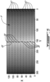
- Fig. 5 depicts the scanned surface and each portion 67 to be analyzed. The width of those portions may vary depending on the required accuracy.
- the algorithm A screens the data points and retains only the data points for the current portion. Such data points are shown at 58 in Fig. 4.
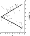
- Fig. 4 illustrates a schematic graph of an exemplary portion analysis, associated with the flow chart of Fig. 3 .
- the algorithm A determines at 59 a cross-section 69 of the portion 67 in the YZ plane using the cloud of data points 62, as shown in Fig. 4 .
- the algorithm A determines at 60 a median line 61 describing the shape of this cross-section 69.
- the algorithm A determines a maximum 30 (the highest point in the Z direction) of the median line 61, and then at 66, the algorithm A computes a polynomial expression that best matches the shape of the median line 61. When plotted, this polynomial expression corresponds to a trend line 6 in Fig. 4 .
- the algorithm A computes the derivative of the polynomial expression and, using the numerical values of this derivative on both sides of the maximum 30, the algorithm A computes a ridge angle ⁇ , herein referred to at 65, for the current analyzed portion.
- the algorithm A determines if the portion 67 just analyzed is the last portion of the scan to be analyzed; if it is not the last portion, then steps 56, 60, 64, 66 and 70 are repeated. As shown in Fig.
- an image of the scanned surface may be created, the maxima 30 representing a plurality of summits making up a ridge line 63, and a mean ridge angle for all portions is computed at 74.
- the algorithm A determines at 76 if the mean ridge angle is above a predetermined threshold angle. If the mean ridge angle is above the threshold angle, the algorithm A selects the severe bend program at 78, whereas if the mean ridge angle is not higher than the threshold angle, the algorithm A selects the moderate bend program at 80.
- a predetermined threshold angle could be predetermined such that this selection would be made from more than two different programs.
- the algorithm A then generates at 82 the program for the robot 44, wherein the maximum 30 of the cross-section 69 of each portion 67 becomes a point on the trajectory of the straightening tool. It is however possible that the algorithm A determines that the trajectory of the tool passes next to at least some of the maxima 30, and thus not directly thereon.
- Fig. 5 exemplifies these maxima 30, the highest deformation points of each determined cross-sections 69 of the scanned portions 67 of the panel 13.
- the series of maxima 30 define the ridge line 63, which corresponds also to the trajectory of the straightening tool.
- the various shades of grey in Fig. 5 indicate the level of deformation, corresponding to displacements of the surface of the panel 13 along the Z axis. The darker zones along left and right sides of the panel 13 show a smaller deformation than that of the lighter grey zones appearing in the middle thereof.
- the exemplary algorithm A selects a straightening strategy, that is a specific combination of parameters (speed, power, etc.) as a function of the level of deformation detected on the panel 13.
- a straightening strategy that is a specific combination of parameters (speed, power, etc.) as a function of the level of deformation detected on the panel 13.
- ⁇ 3 degrees moderate bend at 80
- > 3 degrees severe bend at 78
- the straightening strategies may be obtained by experimental investigation. These straightening strategies take into consideration temperature limits and heating duration limits associated with the panel 13. These limits are specific to the material and are available from the literature, e.g. encyclopaedias.
- the only parameter being adjusted is the laser power level.
- the robot 44 executes at the fourth straightening step 16 the operations specified by the automated straightening controller, which uses the software 42, taking into consideration the defined parameters at the analyzing step 14.
- the operations are contained in the straightening strategy.
- the robot 44 uses a straightening tool 46 with the defined parameter(s) specified at the analyzing step 14 to conduct the straightening process.
- the straightening tool 46 may be, but is not restricted to, a laser, an induction machine, or any other adequate device that can heat or induce heat in the panel 13 to be straightened.
- various controls and adjustments can be provided in the straightening step 16.
- a temperature monitoring device may be used during the straightening process to ensure proper heating temperatures. This temperature monitoring device could be, for example, a pyrometer or an infrared camera.
- applying the straightening strategy is sufficient to straighten to an acceptable level the surface of the panel 13 to be straightened, such that no physical intervention by a constraint mechanism needs to be used.
- both robots 44 and 48 may actually be replaced by a single robot equipped with a tool rack, allowing it to change its own tools.
- the optical sensor 40 may be placed in the tool rack and vice versa.
- the optical measurements could also be conducted almost simultaneously during the straightening process of the straightening step 16.
- the single robot 48 holds both the optical sensor 40 and the straightening tool 46.
- the optical sensor 40 scans the surface of the panel 13 ahead of the straightening tool 46 and sends the scanned data to the controller for analysis at step 12, which defines the required parameters at step 14 and which controls the straightening tool 46 based on those defined parameters.
- Such a continuous online, or real-time measurement and straightening process may then include a system that is directly adaptive during the straightening process.
- Such a system may, for example, adapt the straightening parameters depending on the reaction of the treated area in a "live" or real-time manner.
- the four steps 10, 12, 14 and 16 may also be conducted iteratively until the desired results are obtained. After straightening, a final scan may be performed in order to provide a final distortion report to workers.
- the present method potentially reduces the straightening time, and also reduces the variability related to worker skills and perceptions. Furthermore, the proposed method improves the results and precision of the straightening process. Interestingly, the present straightening process may also contribute to decreasing the weight of a finished vehicle as putty used to even the surface of the external panels of the shell is reduced or even eliminated.
Landscapes
- Engineering & Computer Science (AREA)
- Physics & Mathematics (AREA)
- Mechanical Engineering (AREA)
- Optics & Photonics (AREA)
- Plasma & Fusion (AREA)
- Human Computer Interaction (AREA)
- Manufacturing & Machinery (AREA)
- General Physics & Mathematics (AREA)
- Automation & Control Theory (AREA)
- Length Measuring Devices By Optical Means (AREA)
- Straightening Metal Sheet-Like Bodies (AREA)
- Automobile Manufacture Line, Endless Track Vehicle, Trailer (AREA)
Claims (15)
- Automatisiertes Verfahren zum mindestens teilweisen Korrigieren von Verformungen in einer metallischen Komponente (13) und dergleichen, das Verfahren umfassend:a) Scannen (10) einer verformten Oberfläche der metallischen Komponente, um Daten darüber zu sammeln;b) Vergleichen (12) der gesammelten Daten aus Schritt a) mit einem gewünschten Ergebnis;
dadurch gekennzeichnet, dass das Verfahren ferner umfasst:c) Durchführen einer Analyse (14) der verglichenen Daten aus Schritt b) zum Identifizieren von Punkten mit der größten Verformung von benachbarten Abschnitten der verformten Oberfläche der metallischen Komponente;d) Bestimmen einer Bahn, die im Wesentlichen an mindestens zwei der Punkte mit der größten Verformung vorbeiführt; unde) Ausführen (16) von Korrekturvorgängen an der verformten Oberfläche, umfassend ein Erwärmen der metallischen Komponente (13) entlang der Bahn. - Verfahren nach Anspruch 1, wobei in Schritt a) die verformte Oberfläche mit einem optischen Sensor (40) und/oder einem 3D-Scanner gescannt wird.
- Verfahren nach einem der Ansprüche 1 und 2, wobei die in Schritt a) gesammelten Daten mindestens eines von Messungen und Kennzeichnungen der verformten Oberfläche einschließen.
- Verfahren nach einem der Ansprüche 1 bis 3, wobei zum Vergleichen der Daten und des gewünschten Endergebnisses in Schritt b) und/oder zum Durchführen der Analyse in Schritt c) eine Software (42) verwendet wird.
- Verfahren nach einem der Ansprüche 1 bis 4, wobei in Schritt e) ein Roboter (44) bereitgestellt wird, der angepasst ist, um die Korrekturvorgänge auszuführen, wobei die Korrekturvorgänge durch eine Software (42) spezifiziert werden und auf der in Schritt d) festgelegten Bahn basieren.
- Verfahren nach Anspruch 5, wobei Schritt e) durch Erwärmen der metallischen Komponente (13) unter Verwendung eines Lasers (46) durchgeführt wird, der an dem Roboter (44) montiert ist.
- Verfahren nach einem der Ansprüche 1 bis 6, wobei die Schritte a) und e) durch eine Steuereinrichtung gesteuert werden.
- Verfahren nach Anspruch 7, wobei die Schritte b) und c) ebenfalls durch die Steuereinrichtung gesteuert werden.
- Verfahren nach einem der Ansprüche 1 bis 8, wobei die metallische Komponente eine metallische Platte einschließt oder aus einer metallischen Platte besteht.
- System zum automatischen Korrigieren einer verformten metallischen Komponente (13), das System umfassend:- einen Sensor (40) zum Erfassen einer Oberfläche der metallischen Komponente (13) und zum Erzeugen von Daten, die die erfasste Oberfläche darstellen;- eine Wärmeinduktoruntereinheit (44), die einen Wärmeinduktor (46) einschließt;
wobei das System dadurch gekennzeichnet ist, dass es ferner umfasst:- eine Steuereinheit, die betriebsfähig ist, um die Daten zu analysieren, um Punkte mit der größten Verformung von benachbarten Abschnitten der verformten Oberfläche der metallischen Komponente zu identifizieren und um eine Bahn zu erzeugen, die im Wesentlichen an mindestens zwei der Punkte mit der größten Verformung vorbeiführt, wobei die Bahn verwendet wird, um die Wärmeinduktoruntereinheit (44) zu steuern. - System nach Anspruch 10, wobei die Steuereinrichtung betriebsfähig ist, um mindestens eine Kennlinie zu erzeugen, die verwendet wird, um den Wärmeinduktor (46) zu steuern.
- System nach Anspruch 10 oder 11, wobei die Wärmeinduktoruntereinheit ferner einen Roboterarm umfasst, der Wärmeinduktor (44) an dem Roboterarm angebracht ist, wobei die Steuereinrichtung vorzugsweise betriebsfähig ist, um mindestens eine Kennlinie zu erzeugen, die verwendet wird, um den Roboterarms zu steuern, und vorzugsweise wobei die Steuereinrichtung den Roboterarm so steuert, dass der Wärmeinduktor (44) mit der metallischen Komponente nicht physisch in Kontakt kommt.
- System nach einem der Ansprüche 10 bis 12, wobei der Sensor (40) ein 3D-Scanner ist.
- System nach einem der Ansprüche 10 bis 13, wobei der Wärmeinduktor (46) ein Laser, vorzugsweise ein Schweißlaser ist.
- System nach einem der Ansprüche 10 bis 14, wobei die metallische Komponente eine metallische Platte einschließt oder aus einer metallischen Platte besteht.
Applications Claiming Priority (1)
| Application Number | Priority Date | Filing Date | Title |
|---|---|---|---|
| CA2986676A CA2986676C (en) | 2017-11-24 | 2017-11-24 | Method for automated straightening of welded assemblies |
Publications (2)
| Publication Number | Publication Date |
|---|---|
| EP3488943A1 EP3488943A1 (de) | 2019-05-29 |
| EP3488943B1 true EP3488943B1 (de) | 2025-02-19 |
Family
ID=61008619
Family Applications (1)
| Application Number | Title | Priority Date | Filing Date |
|---|---|---|---|
| EP18206490.7A Active EP3488943B1 (de) | 2017-11-24 | 2018-11-15 | Verfahren zum automatisierten richten von geschweissten baugruppen |
Country Status (5)
| Country | Link |
|---|---|
| US (1) | US10725447B2 (de) |
| EP (1) | EP3488943B1 (de) |
| CN (1) | CN109834136B (de) |
| CA (1) | CA2986676C (de) |
| PL (1) | PL3488943T3 (de) |
Families Citing this family (19)
| Publication number | Priority date | Publication date | Assignee | Title |
|---|---|---|---|---|
| JP2020199611A (ja) * | 2019-06-12 | 2020-12-17 | ファナック株式会社 | 工作機械および工作機械の制御方法 |
| DE102019211447B4 (de) * | 2019-07-31 | 2023-06-01 | Robert Bosch Gmbh | Verfahren zum Laserrichten von Führungsschienen |
| CN110756624B (zh) * | 2019-11-05 | 2021-12-10 | 中信戴卡股份有限公司 | 一种车轮轮辋变形校正装置及方法 |
| CN112222574A (zh) * | 2020-11-18 | 2021-01-15 | 富曜半导体(昆山)有限公司 | 一种氩弧焊电弧校正不绣钢零件的方法 |
| CN112775554A (zh) * | 2020-12-25 | 2021-05-11 | 柳州钢铁股份有限公司 | 一种新型激光打磨轧辊孔型装置及其操作方法 |
| CN112845672B (zh) * | 2020-12-31 | 2022-09-13 | 深圳市荣辉铜铝材料有限公司 | 一种金属板材自动调平方法 |
| CN112893522B (zh) * | 2021-01-20 | 2023-04-28 | 湖北重装重工装备有限公司 | 一种高精度矫平机开口量自动调节系统及方法 |
| CN113145687B (zh) * | 2021-04-12 | 2022-08-05 | 上海交通大学 | 船板焊接变形自动感应矫平集成方法 |
| CN113561457B (zh) * | 2021-08-02 | 2023-04-07 | 安徽纳赫智能科技有限公司 | 一种汽车内饰件的矫形设备 |
| US20230297063A1 (en) * | 2022-03-18 | 2023-09-21 | Promess, Inc. | Method, system, and apparatus for forming a workpiece |
| CN115415378A (zh) * | 2022-09-15 | 2022-12-02 | 北京星航机电装备有限公司 | 一种适用于板料大角度成形的激光弯曲测量系统及方法 |
| CN115401088B (zh) * | 2022-10-18 | 2025-02-28 | 南通中远海运川崎船舶工程有限公司 | 一种组合材的弧度检测矫正装置及矫正方法 |
| FR3144932B1 (fr) * | 2023-01-12 | 2025-09-05 | Lisi Aerospace | Procédé de mise en forme d’une pièce d’équipement comprenant une pale |
| EP4442408B1 (de) * | 2023-04-06 | 2025-07-16 | The University Of Maribor - Faculty Of Mechanical Engineering | System und verfahren zum maschinenunterstützten richten von gehärteten metallwerkstücken |
| DE102023109617A1 (de) * | 2023-04-17 | 2024-10-17 | Leviathan GmbH | Verfahren zum Steuern und/oder Regeln einer Trenneinrichtung während eines Zerlegens einer Rumpfhülle sowie Vorrichtung zum Zerlegen einer Rumpfhülle |
| KR102901120B1 (ko) * | 2023-08-07 | 2025-12-17 | 대구대학교 산학협력단 | 잔류 응력을 능동적으로 제거하는 교정 모션제어 서보 시스템 |
| CN119077224A (zh) * | 2024-08-05 | 2024-12-06 | 中车长春轨道客车股份有限公司 | 薄板波浪变形数字化复原方法 |
| CN119657697B (zh) * | 2024-12-30 | 2025-10-24 | 上海柏楚电子科技股份有限公司 | 管材矫平方法、装置、电子设备与存储介质 |
| CN119783228A (zh) * | 2025-03-07 | 2025-04-08 | 中国汽车技术研究中心有限公司 | 铸件矫直方法、装置、系统及设备 |
Family Cites Families (19)
| Publication number | Priority date | Publication date | Assignee | Title |
|---|---|---|---|---|
| US4425776A (en) | 1979-10-17 | 1984-01-17 | Industrial Metal Products Corporation | Production workpiece straightening system |
| DE19653569C2 (de) | 1996-12-20 | 1999-07-22 | Witels App Masch Albert Gmbh | Verfahren zur automatisierten Führung eines Richtprozesses |
| US6298310B1 (en) * | 1997-09-29 | 2001-10-02 | Mitsubishi Heavy Industries, Ltd. | Method and system for determining heating point and heating line in bending of steel plate |
| DE19804577C2 (de) * | 1998-02-05 | 2001-10-31 | Fraunhofer Ges Forschung | Verfahren und Vorrichtung zur Beseitigung von Formabweichungen an metallischen Bauteilen |
| EP1296798B1 (de) * | 2000-07-06 | 2009-02-18 | Trico Products Company | Verfahren und vorrichtung zur flexiblen fertigung von gekrümmten einzelartikeln |
| GB0119023D0 (en) * | 2001-08-03 | 2001-09-26 | Norsk Hydro As | Method and apparatus for distorting a workpiece |
| US20090045243A1 (en) * | 2007-08-16 | 2009-02-19 | Zhi-Huei Young | Butt welding and feeding machine |
| DE102008003882B4 (de) | 2008-01-10 | 2011-12-15 | Otto Fuchs Kg | Verfahren zum Herstellen eines Gegenstandes aus Metall, insbesondere aus einer hochfesten Aluminiumlegierung sowie Verfahren zum Richten eines solchen Gegenstandes |
| CN102039424A (zh) * | 2009-10-10 | 2011-05-04 | 上海船厂船舶有限公司 | 船用艉轴的矫正方法 |
| FI20115326A0 (fi) * | 2011-04-05 | 2011-04-05 | Zenrobotics Oy | Menetelmä sensorin mittausten mitätöimiseksi poimintatoiminnon jälkeen robottijärjestelmässä |
| CN102601166A (zh) * | 2012-03-05 | 2012-07-25 | 上海海事大学 | 一种基于支持向量机的工件变形矫正方法 |
| CN202523112U (zh) * | 2012-04-09 | 2012-11-07 | 北京拓博尔机器人科技有限公司 | 一种机器人激光扫描重建三维模型系统 |
| CN103752651B (zh) | 2014-01-09 | 2015-09-09 | 上海飞机制造有限公司 | 焊接整体壁板激光冲击校形方法 |
| WO2015162445A1 (fr) * | 2014-04-25 | 2015-10-29 | Arcelormittal Investigación Y Desarrollo Sl | Procede et dispositif de preparation de toles d'acier aluminiees destinees a etre soudees puis durcies sous presse; flan soude correspondant |
| US10195636B2 (en) * | 2014-06-24 | 2019-02-05 | United States Gypsum Company | Automatic dispensing device for wallboard joint taping |
| US20160016255A1 (en) | 2014-07-17 | 2016-01-21 | Siemens Energy, Inc. | Laser correction of metal deformation |
| CN105665480B (zh) * | 2016-03-17 | 2018-03-02 | 广西科技大学 | 一种动臂自动矫正装置及矫正方法 |
| CN106270005B (zh) * | 2016-08-25 | 2018-05-15 | 广东工业大学 | 一种叶片激光喷丸校形的方法与装置 |
| CN107008996B (zh) * | 2017-06-02 | 2019-05-07 | 河南科技大学 | 一种金属冷焊增材制造的方法 |
-
2017
- 2017-11-24 CA CA2986676A patent/CA2986676C/en active Active
-
2018
- 2018-10-24 US US16/169,224 patent/US10725447B2/en active Active
- 2018-11-15 PL PL18206490.7T patent/PL3488943T3/pl unknown
- 2018-11-15 EP EP18206490.7A patent/EP3488943B1/de active Active
- 2018-11-26 CN CN201811418870.5A patent/CN109834136B/zh active Active
Also Published As
| Publication number | Publication date |
|---|---|
| US20190163162A1 (en) | 2019-05-30 |
| US10725447B2 (en) | 2020-07-28 |
| CA2986676A1 (en) | 2018-01-26 |
| CN109834136B (zh) | 2021-01-08 |
| CA2986676C (en) | 2020-01-07 |
| EP3488943A1 (de) | 2019-05-29 |
| CN109834136A (zh) | 2019-06-04 |
| PL3488943T3 (pl) | 2025-06-16 |
Similar Documents
| Publication | Publication Date | Title |
|---|---|---|
| US10725447B2 (en) | Method for automated straightening of welded assemblies | |
| US6024273A (en) | Method and system for determining weld bead quality | |
| US6969821B2 (en) | Airfoil qualification system and method | |
| JP5981143B2 (ja) | ロボットツールの制御方法 | |
| CN114072248B (zh) | 用于定向能量沉积增材制造系统的喷距监测和控制 | |
| US11565344B2 (en) | Device and method for learning focal position offset of laser processing apparatus, and laser processing system correcting focal position offset | |
| CN118438446A (zh) | 一种焊接机器人轨迹的规划方法 | |
| US20160016255A1 (en) | Laser correction of metal deformation | |
| JP7407277B2 (ja) | 金属管の製造方法と装置 | |
| Xiong et al. | Active vision sensing and feedback control of back penetration for thin sheet aluminum alloy in pulsed MIG suspension welding | |
| CN118357649B (zh) | 一种自动校正的智能焊接系统 | |
| US10481577B2 (en) | System and method for object distance detection and positioning | |
| US10527353B2 (en) | Workpiece transfer apparatus for furnace | |
| EP3406383B1 (de) | Verfahren zum schneiden von öffnungen in flache, konkave, konvergierende und gewölbte flächen und zum schweissen von flachen, konkaven, konvergierenden und konvexen oberflächen eines werkstücks | |
| CN120540071B (zh) | 一种激光焊接轨迹实时优化控制系统 | |
| US10864572B2 (en) | In-situ hot working and heat treatment of additively manufactured metallic alloys | |
| EP1423218B1 (de) | Verfahren und vorrichtung zur verformung eines werkstücks | |
| EP4337397B1 (de) | Automatisierte anlage zur biegung/krümmung von elementen mit im wesentlichen länglicher entwicklung sowie verfahren zur durchführung der biegung/krümmung mittels dieser anlage. | |
| KR102735495B1 (ko) | 곡형 부재 제작 시스템 | |
| KR20160125210A (ko) | 컨베이어 연동의 로봇 동기 제어방법 | |
| US20180369944A1 (en) | Method of cutting openings in flat, concave, converging, and convex surfaces, and welding flat, concave, converging, and convex surfaces of a workpiece | |
| JP2025070014A (ja) | インクリメンタル成形方法 | |
| CN121870345A (zh) | 一种感应加热矫正焊接变形过程中矫正参数实时调整方法 | |
| CN121339246A (zh) | 超高强钢滚压成形方法、系统、电子设备及存储介质 | |
| CN122033500A (zh) | 自动焊接控制方法和系统 |
Legal Events
| Date | Code | Title | Description |
|---|---|---|---|
| PUAI | Public reference made under article 153(3) epc to a published international application that has entered the european phase |
Free format text: ORIGINAL CODE: 0009012 |
|
| STAA | Information on the status of an ep patent application or granted ep patent |
Free format text: STATUS: REQUEST FOR EXAMINATION WAS MADE |
|
| 17P | Request for examination filed |
Effective date: 20181115 |
|
| AK | Designated contracting states |
Kind code of ref document: A1 Designated state(s): AL AT BE BG CH CY CZ DE DK EE ES FI FR GB GR HR HU IE IS IT LI LT LU LV MC MK MT NL NO PL PT RO RS SE SI SK SM TR |
|
| AX | Request for extension of the european patent |
Extension state: BA ME |
|
| RBV | Designated contracting states (corrected) |
Designated state(s): AL AT BE BG CH CY CZ DE DK EE ES FI FR GB GR HR HU IE IS IT LI LT LU LV MC MK MT NL NO PL PT RO RS SE SI SK SM TR |
|
| R17P | Request for examination filed (corrected) |
Effective date: 20181115 |
|
| STAA | Information on the status of an ep patent application or granted ep patent |
Free format text: STATUS: EXAMINATION IS IN PROGRESS |
|
| 17Q | First examination report despatched |
Effective date: 20220614 |
|
| RAP1 | Party data changed (applicant data changed or rights of an application transferred) |
Owner name: ALSTOM HOLDINGS |
|
| P01 | Opt-out of the competence of the unified patent court (upc) registered |
Effective date: 20230822 |
|
| GRAP | Despatch of communication of intention to grant a patent |
Free format text: ORIGINAL CODE: EPIDOSNIGR1 |
|
| STAA | Information on the status of an ep patent application or granted ep patent |
Free format text: STATUS: GRANT OF PATENT IS INTENDED |
|
| RIC1 | Information provided on ipc code assigned before grant |
Ipc: B23K 103/10 20060101ALN20241002BHEP Ipc: B23K 103/04 20060101ALN20241002BHEP Ipc: B21D 11/20 20060101ALN20241002BHEP Ipc: B23Q 17/20 20060101ALI20241002BHEP Ipc: G05B 19/401 20060101ALI20241002BHEP Ipc: G05B 19/404 20060101ALI20241002BHEP Ipc: B23K 26/03 20060101ALI20241002BHEP Ipc: B23K 31/00 20060101ALI20241002BHEP Ipc: B23K 26/21 20140101ALI20241002BHEP Ipc: B23K 26/70 20140101ALI20241002BHEP Ipc: B23K 26/352 20140101ALI20241002BHEP Ipc: B23K 26/32 20140101ALI20241002BHEP Ipc: B21D 3/00 20060101ALI20241002BHEP Ipc: B21D 1/00 20060101AFI20241002BHEP |
|
| INTG | Intention to grant announced |
Effective date: 20241017 |
|
| GRAS | Grant fee paid |
Free format text: ORIGINAL CODE: EPIDOSNIGR3 |
|
| GRAA | (expected) grant |
Free format text: ORIGINAL CODE: 0009210 |
|
| STAA | Information on the status of an ep patent application or granted ep patent |
Free format text: STATUS: THE PATENT HAS BEEN GRANTED |
|
| AK | Designated contracting states |
Kind code of ref document: B1 Designated state(s): AL AT BE BG CH CY CZ DE DK EE ES FI FR GB GR HR HU IE IS IT LI LT LU LV MC MK MT NL NO PL PT RO RS SE SI SK SM TR |
|
| REG | Reference to a national code |
Ref country code: GB Ref legal event code: FG4D |
|
| REG | Reference to a national code |
Ref country code: CH Ref legal event code: EP |
|
| REG | Reference to a national code |
Ref country code: DE Ref legal event code: R096 Ref document number: 602018079278 Country of ref document: DE |
|
| REG | Reference to a national code |
Ref country code: IE Ref legal event code: FG4D |
|
| REG | Reference to a national code |
Ref country code: NL Ref legal event code: MP Effective date: 20250219 |
|
| PG25 | Lapsed in a contracting state [announced via postgrant information from national office to epo] |
Ref country code: RS Free format text: LAPSE BECAUSE OF FAILURE TO SUBMIT A TRANSLATION OF THE DESCRIPTION OR TO PAY THE FEE WITHIN THE PRESCRIBED TIME-LIMIT Effective date: 20250519 |
|
| PG25 | Lapsed in a contracting state [announced via postgrant information from national office to epo] |
Ref country code: FI Free format text: LAPSE BECAUSE OF FAILURE TO SUBMIT A TRANSLATION OF THE DESCRIPTION OR TO PAY THE FEE WITHIN THE PRESCRIBED TIME-LIMIT Effective date: 20250219 |
|
| PG25 | Lapsed in a contracting state [announced via postgrant information from national office to epo] |
Ref country code: ES Free format text: LAPSE BECAUSE OF FAILURE TO SUBMIT A TRANSLATION OF THE DESCRIPTION OR TO PAY THE FEE WITHIN THE PRESCRIBED TIME-LIMIT Effective date: 20250219 |
|
| REG | Reference to a national code |
Ref country code: LT Ref legal event code: MG9D |
|
| PG25 | Lapsed in a contracting state [announced via postgrant information from national office to epo] |
Ref country code: IS Free format text: LAPSE BECAUSE OF FAILURE TO SUBMIT A TRANSLATION OF THE DESCRIPTION OR TO PAY THE FEE WITHIN THE PRESCRIBED TIME-LIMIT Effective date: 20250619 Ref country code: NO Free format text: LAPSE BECAUSE OF FAILURE TO SUBMIT A TRANSLATION OF THE DESCRIPTION OR TO PAY THE FEE WITHIN THE PRESCRIBED TIME-LIMIT Effective date: 20250519 |
|
| PG25 | Lapsed in a contracting state [announced via postgrant information from national office to epo] |
Ref country code: NL Free format text: LAPSE BECAUSE OF FAILURE TO SUBMIT A TRANSLATION OF THE DESCRIPTION OR TO PAY THE FEE WITHIN THE PRESCRIBED TIME-LIMIT Effective date: 20250219 |
|
| PG25 | Lapsed in a contracting state [announced via postgrant information from national office to epo] |
Ref country code: HR Free format text: LAPSE BECAUSE OF FAILURE TO SUBMIT A TRANSLATION OF THE DESCRIPTION OR TO PAY THE FEE WITHIN THE PRESCRIBED TIME-LIMIT Effective date: 20250219 |
|
| PG25 | Lapsed in a contracting state [announced via postgrant information from national office to epo] |
Ref country code: LV Free format text: LAPSE BECAUSE OF FAILURE TO SUBMIT A TRANSLATION OF THE DESCRIPTION OR TO PAY THE FEE WITHIN THE PRESCRIBED TIME-LIMIT Effective date: 20250219 Ref country code: PT Free format text: LAPSE BECAUSE OF FAILURE TO SUBMIT A TRANSLATION OF THE DESCRIPTION OR TO PAY THE FEE WITHIN THE PRESCRIBED TIME-LIMIT Effective date: 20250620 |
|
| PG25 | Lapsed in a contracting state [announced via postgrant information from national office to epo] |
Ref country code: GR Free format text: LAPSE BECAUSE OF FAILURE TO SUBMIT A TRANSLATION OF THE DESCRIPTION OR TO PAY THE FEE WITHIN THE PRESCRIBED TIME-LIMIT Effective date: 20250520 Ref country code: BG Free format text: LAPSE BECAUSE OF FAILURE TO SUBMIT A TRANSLATION OF THE DESCRIPTION OR TO PAY THE FEE WITHIN THE PRESCRIBED TIME-LIMIT Effective date: 20250219 |
|
| REG | Reference to a national code |
Ref country code: AT Ref legal event code: MK05 Ref document number: 1767826 Country of ref document: AT Kind code of ref document: T Effective date: 20250219 |
|
| PG25 | Lapsed in a contracting state [announced via postgrant information from national office to epo] |
Ref country code: SE Free format text: LAPSE BECAUSE OF FAILURE TO SUBMIT A TRANSLATION OF THE DESCRIPTION OR TO PAY THE FEE WITHIN THE PRESCRIBED TIME-LIMIT Effective date: 20250219 |
|
| PG25 | Lapsed in a contracting state [announced via postgrant information from national office to epo] |
Ref country code: SM Free format text: LAPSE BECAUSE OF FAILURE TO SUBMIT A TRANSLATION OF THE DESCRIPTION OR TO PAY THE FEE WITHIN THE PRESCRIBED TIME-LIMIT Effective date: 20250219 |
|
| PG25 | Lapsed in a contracting state [announced via postgrant information from national office to epo] |
Ref country code: DK Free format text: LAPSE BECAUSE OF FAILURE TO SUBMIT A TRANSLATION OF THE DESCRIPTION OR TO PAY THE FEE WITHIN THE PRESCRIBED TIME-LIMIT Effective date: 20250219 |
|
| PG25 | Lapsed in a contracting state [announced via postgrant information from national office to epo] |
Ref country code: IT Free format text: LAPSE BECAUSE OF FAILURE TO SUBMIT A TRANSLATION OF THE DESCRIPTION OR TO PAY THE FEE WITHIN THE PRESCRIBED TIME-LIMIT Effective date: 20250219 |
|
| PG25 | Lapsed in a contracting state [announced via postgrant information from national office to epo] |
Ref country code: AT Free format text: LAPSE BECAUSE OF FAILURE TO SUBMIT A TRANSLATION OF THE DESCRIPTION OR TO PAY THE FEE WITHIN THE PRESCRIBED TIME-LIMIT Effective date: 20250219 |
|
| PG25 | Lapsed in a contracting state [announced via postgrant information from national office to epo] |
Ref country code: EE Free format text: LAPSE BECAUSE OF FAILURE TO SUBMIT A TRANSLATION OF THE DESCRIPTION OR TO PAY THE FEE WITHIN THE PRESCRIBED TIME-LIMIT Effective date: 20250219 |
|
| PG25 | Lapsed in a contracting state [announced via postgrant information from national office to epo] |
Ref country code: RO Free format text: LAPSE BECAUSE OF FAILURE TO SUBMIT A TRANSLATION OF THE DESCRIPTION OR TO PAY THE FEE WITHIN THE PRESCRIBED TIME-LIMIT Effective date: 20250219 |
|
| PG25 | Lapsed in a contracting state [announced via postgrant information from national office to epo] |
Ref country code: SK Free format text: LAPSE BECAUSE OF FAILURE TO SUBMIT A TRANSLATION OF THE DESCRIPTION OR TO PAY THE FEE WITHIN THE PRESCRIBED TIME-LIMIT Effective date: 20250219 |
|
| REG | Reference to a national code |
Ref country code: DE Ref legal event code: R097 Ref document number: 602018079278 Country of ref document: DE |
|
| PLBE | No opposition filed within time limit |
Free format text: ORIGINAL CODE: 0009261 |
|
| STAA | Information on the status of an ep patent application or granted ep patent |
Free format text: STATUS: NO OPPOSITION FILED WITHIN TIME LIMIT |
|
| PGFP | Annual fee paid to national office [announced via postgrant information from national office to epo] |
Ref country code: FR Payment date: 20251126 Year of fee payment: 8 |
|
| PGFP | Annual fee paid to national office [announced via postgrant information from national office to epo] |
Ref country code: CZ Payment date: 20251111 Year of fee payment: 8 |
|
| PGFP | Annual fee paid to national office [announced via postgrant information from national office to epo] |
Ref country code: PL Payment date: 20251107 Year of fee payment: 8 |
|
| 26N | No opposition filed |
Effective date: 20251120 |