EP3488910A2 - Vorrichtung zur reinigung eines fluids mittels eines filterbetts - Google Patents
Vorrichtung zur reinigung eines fluids mittels eines filterbetts Download PDFInfo
- Publication number
- EP3488910A2 EP3488910A2 EP18207891.5A EP18207891A EP3488910A2 EP 3488910 A2 EP3488910 A2 EP 3488910A2 EP 18207891 A EP18207891 A EP 18207891A EP 3488910 A2 EP3488910 A2 EP 3488910A2
- Authority
- EP
- European Patent Office
- Prior art keywords
- cleaning
- housing
- airlift
- filter
- cleaning liquid
- Prior art date
- Legal status (The legal status is an assumption and is not a legal conclusion. Google has not performed a legal analysis and makes no representation as to the accuracy of the status listed.)
- Withdrawn
Links
- 239000012530 fluid Substances 0.000 title description 2
- 238000000746 purification Methods 0.000 title 1
- 238000004140 cleaning Methods 0.000 claims abstract description 138
- 239000007788 liquid Substances 0.000 claims abstract description 85
- 238000001914 filtration Methods 0.000 claims abstract description 75
- 238000009826 distribution Methods 0.000 claims abstract description 27
- 238000005276 aerator Methods 0.000 claims abstract description 25
- 230000005484 gravity Effects 0.000 claims abstract description 22
- 238000004891 communication Methods 0.000 claims abstract description 18
- 238000007599 discharging Methods 0.000 claims abstract description 11
- VYPSYNLAJGMNEJ-UHFFFAOYSA-N Silicium dioxide Chemical compound O=[Si]=O VYPSYNLAJGMNEJ-UHFFFAOYSA-N 0.000 claims description 72
- 239000004576 sand Substances 0.000 claims description 59
- 239000000463 material Substances 0.000 claims description 25
- 239000013013 elastic material Substances 0.000 claims description 20
- 239000000377 silicon dioxide Substances 0.000 claims description 6
- XLYOFNOQVPJJNP-UHFFFAOYSA-N water Substances O XLYOFNOQVPJJNP-UHFFFAOYSA-N 0.000 claims description 6
- 229920000915 polyvinyl chloride Polymers 0.000 claims description 5
- 239000004800 polyvinyl chloride Substances 0.000 claims description 5
- RRHGJUQNOFWUDK-UHFFFAOYSA-N Isoprene Chemical compound CC(=C)C=C RRHGJUQNOFWUDK-UHFFFAOYSA-N 0.000 claims description 4
- 229920001971 elastomer Polymers 0.000 claims description 4
- 229920001195 polyisoprene Polymers 0.000 claims description 4
- 239000002245 particle Substances 0.000 description 7
- 230000008901 benefit Effects 0.000 description 6
- 230000004888 barrier function Effects 0.000 description 5
- 238000004519 manufacturing process Methods 0.000 description 4
- 238000000034 method Methods 0.000 description 4
- 230000008092 positive effect Effects 0.000 description 4
- 230000008569 process Effects 0.000 description 4
- 239000003344 environmental pollutant Substances 0.000 description 3
- 231100000719 pollutant Toxicity 0.000 description 3
- 238000009827 uniform distribution Methods 0.000 description 3
- 230000000694 effects Effects 0.000 description 2
- 239000007791 liquid phase Substances 0.000 description 2
- 229920000642 polymer Polymers 0.000 description 2
- 230000009467 reduction Effects 0.000 description 2
- 229910001220 stainless steel Inorganic materials 0.000 description 2
- 239000010935 stainless steel Substances 0.000 description 2
- 230000002411 adverse Effects 0.000 description 1
- 230000000739 chaotic effect Effects 0.000 description 1
- 238000005352 clarification Methods 0.000 description 1
- 239000000701 coagulant Substances 0.000 description 1
- 239000000470 constituent Substances 0.000 description 1
- 238000010276 construction Methods 0.000 description 1
- 239000000356 contaminant Substances 0.000 description 1
- 238000011109 contamination Methods 0.000 description 1
- 230000007812 deficiency Effects 0.000 description 1
- 230000035622 drinking Effects 0.000 description 1
- 239000003651 drinking water Substances 0.000 description 1
- 230000008030 elimination Effects 0.000 description 1
- 238000003379 elimination reaction Methods 0.000 description 1
- 239000004744 fabric Substances 0.000 description 1
- 230000006872 improvement Effects 0.000 description 1
- 239000013072 incoming material Substances 0.000 description 1
- 239000008235 industrial water Substances 0.000 description 1
- 230000007774 longterm Effects 0.000 description 1
- 230000007246 mechanism Effects 0.000 description 1
- 238000005192 partition Methods 0.000 description 1
- 239000011150 reinforced concrete Substances 0.000 description 1
- 239000000725 suspension Substances 0.000 description 1
- 230000007704 transition Effects 0.000 description 1
- 239000011800 void material Substances 0.000 description 1
- 238000005406 washing Methods 0.000 description 1
- 239000002351 wastewater Substances 0.000 description 1
Images

Classifications
-
- B—PERFORMING OPERATIONS; TRANSPORTING
- B01—PHYSICAL OR CHEMICAL PROCESSES OR APPARATUS IN GENERAL
- B01D—SEPARATION
- B01D24/00—Filters comprising loose filtering material, i.e. filtering material without any binder between the individual particles or fibres thereof
- B01D24/46—Regenerating the filtering material in the filter
- B01D24/4668—Regenerating the filtering material in the filter by moving the filtering element
- B01D24/4689—Displacement of the filtering material to a compartment of the filtering device for regeneration
-
- B—PERFORMING OPERATIONS; TRANSPORTING
- B01—PHYSICAL OR CHEMICAL PROCESSES OR APPARATUS IN GENERAL
- B01D—SEPARATION
- B01D24/00—Filters comprising loose filtering material, i.e. filtering material without any binder between the individual particles or fibres thereof
- B01D24/28—Filters comprising loose filtering material, i.e. filtering material without any binder between the individual particles or fibres thereof with the filter bed moving during the filtration
- B01D24/30—Translation
Definitions
- the invention relates to filters, more precisely to filters containing powdery filtering medium that can be used to purify drinking, industrial or waste water.
- filters in which sand is used as a powdery filtering medium there are various types of filters in which sand is used as a powdery filtering medium.
- the above types include gravity sand filters, including self-cleaning continuous filters and rapid filters (contact filters).
- self-cleaning continuous filters the airlift capacity is designed for the load driving the filtering medium, which indicates that, based on the characteristics of sand as the filtering medium, its sliding moment is limited. This limitation is due to two cone-shaped elements, one of which is directed upwards, while another one is a hollow cone connected to the housing with an end directed downwards, and the above-mentioned elements constitute a distribution chamber in the form of a ring.
- the airlift provides fastener lift of the sand before the sand mass begins moving downwards.
- the filtration is directed from top to bottom; besides the filters are designed so as to wash the filtering medium by themselves. And in the rapid filters the filtration is directed from bottom to top, and it is necessary to stop the filtration process for washing the filtering medium.
- the above filters have a number of identical units and elements that ensure their smooth operation.
- Such elements and units include a housing, filtering medium in the form of sand, sand and liquid distribution units, etc.
- a filter for continuous liquid cleaning comprising a housing that consists of a cylinder-shaped part and a hollow cone-shaped part connected to each other, a distributing element, an airlift installed axially and a filtering element placed above the airlift, comprising sand as a filtering medium and being composed of the external and internal cylinder-shaped elements with a zigzag channel configured therebetween to pass through the contaminated filtering medium, with its simultaneous cleaning, the cleaning being provided with cleaning water counterflow.
- the cleaned filtering medium is returned to the filtering medium layer in the housing, while the cleaning liquid with the contaminated medium is removed by the tube for discharging.
- a continuous filtration system comprising a housing, a cavity with a base in the form of a cone, a inlet for liquid to be cleaned, with tubes for discharging the cleaned and cleaning liquid, a filtering medium in the form of silica sand placed in the housing, a filtering unit fixed along the vertical axis of the housing, which in turn contains an airlift, a cleaning element fixed over the airlift, an air tank configured to connect to a forced air source, wherein the cleaning element is formed of two parts, the lower part has one compartment with a zigzag channel formed therein, and the upper part has two concentrically located compartments, the internal and the external ones, and a tube for cleaning liquid drainage, in communication with the latter, furthermore, in the upper part of the cleaning element a valve is provided, wherein the filter has sand and liquid distribution units, said units being concentric with respect to each other and the airlift, wherein the sand distribution unit is a truncated cone-shaped element with the end directed
- a rapid filter is known as well, the filter comprising a housing with a filtering medium and a liquid distribution unit located therein.
- the liquid distribution unit is in the form of transverse perforated tubes connected to the supply tube.
- the housing is equipped with a partition that actually divides it into two concentric parts.
- the filtered material is accumulated in the external part and actually creates a pillow of liquid.
- the filter is also provided with a shield that actually provides a curved motion of the liquid to be cleaned.
- the high cost of filtering medium is associated with a high probability of removing sand particles, together with residual contaminants, from the cleaning unit, which in turn reduces the duration of the filtration cycle and increases operating costs.
- a gravity sand filter in particular, a self-cleaning continuous filter, comprising a housing, a cavity with a base in the form of a cone, an inlet for liquid to be cleaned, with tubes for discharging the cleaned and cleaning liquid, a filtering medium in the form of silica sand placed in the housing, a structurally combined unit, fixed along the vertical axis of the housing, which in turn contains an airlift with an air tank that is configured in communication with a forced air source, a two-part cleaning element, fixed over the airlift, wherein the lower part has one compartment with a zigzag channel, and the upper part has two concentrically located compartments, the internal and the external ones, and a tube for cleaning liquid drainage, in communication with the latter; furthermore, the filter has sand and liquid distribution units, wherein the sand distribution unit is made in the form of a cone-shaped element with an end directed to the top, while the liquid distribution unit is made in
- the filter is further equipped with a vibration aerator, which is inserted or configured to be inserted into the zigzag channel of the cleaning element lower part of the filtering device, and/or with a means for pressure and speed reducing of the upward flow of the cleaning liquid in the internal compartment of the upper part of the cleaning unit, and/or with a means for providing the airlift vibration.
- a vibration aerator which is inserted or configured to be inserted into the zigzag channel of the cleaning element lower part of the filtering device, and/or with a means for pressure and speed reducing of the upward flow of the cleaning liquid in the internal compartment of the upper part of the cleaning unit, and/or with a means for providing the airlift vibration.
- a gravity sand filter in particular a rapid filter, comprising a housing, an inlet for a liquid to be cleaned, with tubes for discharging the cleaned and cleaning liquid, a filtering medium in the form of silica sand placed in the housing, and a liquid distribution unit, which is located at the bottom of the housing, and a structurally combined unit, fixed along the vertical axis of the housing, which in turn contains an airlift with an air tank that is configured in communication with a forced air source, a two-part cleaning element, fixed over the airlift, wherein the lower part has a compartment with a zigzag channel, and the lower part has two concentrically located compartments, the internal and the external ones, and a tube for cleaning liquid drainage, in communication with the latter; furthermore, the filter has a sand distribution unit provided on the internal wall of the housing in the form of a directional bevel, and a system of tubes connected to the airlift by means of a discharge chamber, in the bottom part,
- the structurally combined unit for gravity sand filters which may be used for upgrading said filters and comprises an airlift with an air tank, configured in communication with a forced air source, a two-part cleaning element, fixed over the airlift, the lower part having one compartment with a zigzag channel, the upper part having two concentrically located compartments, the internal and the external ones, and a tube for cleaning liquid drainage, in communication with the latter.
- the system of tubes is connected with the airlift in the bottom part by means of a discharge chamber, each tube of the system being formed by inclined and vertical parts and equipped with suction means, wherein the device further comprises a module for controlling said suction means, the airlift has an additional air tank in communication with a forced air source to provide double rise, in addition, it is further equipped with vibration aerator, which is inserted or configured to be inserted into the zigzag unit of the cleaning unit lower part of the filtering unit and/or with a means for reducing pressure and speed of the cleaning liquid upward flow in the internal compartment of the cleaning unit upper part and/or with a means for providing the airlift vibration.
- the vibration aerator comprises a tubular housing in the form of a ring, provided with holes formed in the central groove along the entire length of the internal surface, wherein the housing is inserted into the filtering material and elastic material balls are placed in its cavity, and it is further equipped with a tube for communicating the cavity of the housing with a forced air source.
- the vibration aerator comprises a housing, consisting of two tubular parts in the form of a half ring, each part being closed at the end surfaces and comprising a central groove provided with holes formed therein along the entire length of the internal surface, each part of the housing being inserted into filtering material, with elastic material balls placed in its cavity, furthermore, the above part is provided with tubes, respectively, for communicating the individual cavities with a forced air source.
- the filtering material is made of polyvinyl chloride.
- the means for providing the airlift vibration for the continuous filters is configured in the form elastic material balls, located in the air tank, fixed thereon, while for the rapid filters - in the form of elastic material balls, located in a slot, formed in the discharge chamber.
- the elastic material balls are made, for example, of rubber or caoutchouc.
- the means for reducing pressure and speed of the cleaning liquid upper flow in the internal compartment of the cleaning element upper part is configured at least in the form of one inclined flap with one end attached to a wall of the internal compartment and with the other end located at a distance from the opposite wall, wherein in the case of one or more flaps they are arranged in a mutually movable manner in the vertical plane and so each subsequent flap is attached to the wall, opposite of the one holding the preceding flap.
- the means for reducing pressure and speed of the cleaning liquid upper flow in the internal compartment of the cleaning element upper part is configured at least in the form of an inclined tube that discharges the cleaning liquid in one external compartment, each tube being equipped with a valve for controlling the cleaning liquid level.
- the technical effect of the invention is a complete cleaning of the filtering medium, improving the quality of the filtered material, reducing the cost of filtering media and operation, increasing productivity and reducing the cleaning liquid usage rate.
- both gravity sand filters, the continuous and the rapid one, according to the invention, in both embodiments, are equipped with a vibratory aerator in a zigzag channel formed in the lower part compartment of the cleaning unit, because the uniform distribution of sand used as a filtering medium is provided in the central part of the filter and a massive return of sand during the air supply forced mode is caused, in addition, with the sand movement along the zigzag channel from top to bottom the above-mentioned vibration aerator provides bringing it into suspension by the counterflow and removing residual contamination due to colliding particles.
- a complete cleaning of the filtering medium is also ensured by the upper part of the cleaning unit, in particular, together with providing artificial barriers in the internal compartment connected to the zigzag channel in the form of an inclined tube or inclined flaps for moving the cleaning liquid into the external compartment, since they ensure that the floating sand particles remaining in the cleaning liquid will be captured and returned back, because due to reducing the pressure and flow rate, their low value can no longer let the sand into the external compartment to be withdrawn outward through the tube for discharging.
- Such a barrier system has a positive effect when using full water-air load.
- such a structure of the cleaning element makes it possible to reduce the dimensions of some units or elements.
- the size of the zigzag channel is about up to 40%, which in itself leads to a reduction in the production or operation cost.
- the provision of airlift with vibration means results in a consistent, measured and uniform movement of the filtering medium over the entire filter area, respectively, eliminates the possibility of changing vibrations due to the amplitude equalization and the process of uneven suction in the part of the cone-shaped bottom of the housing due to the changes in the mixed masses liquid phases is brought to a minimum.
- the embodiment of the vibrating aerator is such that it can be made separately, and quite simply, without applying extra effort, inserted into already existing continuous filters, or can be made together with said filters.
- the embodiment of the airlift vibrating means provides the same opportunity, since the air tanks are already provided in such filters and the arrangement of elastic balls of the appropriate size is not a problem as well.
- said means may be made together with filters as well.
- Another advantage of the invention is that, due to their design or modernization, rapid filters are transformed into continuous filters that do not require stopping the filtration process and switching to the cleaning mode, in which case the filtering medium is cleaned and the filtration proceeds continuously.
- the advantage of the invention consists in providing a sand distribution unit construction for the rapid self-cleaning filters.
- the embodiment of this unit allows for a uniform distribution of sand as filtering medium, due to the specific configuration of the system of tubes (inclined, cone-shaped) and the directional bevel inside the housing.
- the location of the discharge chamber in this unit provides the principle of lifting in two stages. This makes the device more efficient.
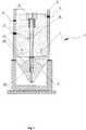
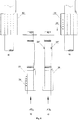
- a gravity sand filter in particular a self-cleaning continuous filter, comprises a housing 1, consisting in a supported body 2 and a base 3 in the form of a void cone.
- the housing is equipped with tubes 4, 5 and 6 for inputting the liquid to be cleaned and for discharging the cleaned and cleaning liquid, respectively.
- a filtering medium 7 in the form of silica sand is placed in the housing.
- a structurally combined unit is fixed, being a filtering unit, which in turn contains an airlift 8, a cleaning element 9 installed above the airlift, an air tank 10 configured to be connected to a forced air source.
- a liquid distribution unit 11 in the form of a perforated jacket located on the airlift, and a sand distribution unit 12, in the form of a cone-shaped element with the end directed to the top.
- the supported body and the base body of the housing can be made of reinforced concrete, while the base in the form of a cone can be made of stainless steel.
- the cleaning element can also be made of stainless steel and formed of two parts.
- the lower part 13 has one compartment with a zigzag channel 14 formed in it, while the upper part has two concentrically located compartments 15 and 16, the internal and the external ones, respectively.
- a barrier is provided in the internal compartment to reduce the pressure and speed of the upward flow of cleaning liquid.
- the barrier is a means that is made at least in the form of one inclined flap 17, which is attached with its one end to one of the internal compartment walls, and its other end is located at a distance from the opposite wall.
- flap system they are positioned in a vertical plane, mutually movable and in such a way that each subsequent flap is attached to the wall, opposite of the one holding the preceding flap.
- the means for reducing pressure and speed of the cleaning liquid upper flow in the internal compartment of the cleaning element upper part is configured at least in the form of an inclined tube or tubes 18 discharging the cleaning liquid from the internal compartment into the external compartment, the above tubes being equipped with a valve(s) 19 for controlling the cleaning liquid level; obviously, such embodiments do not exclude the possibility of combining them in any form, for example, the means for reducing pressure and speed of the cleaning liquid upper flow in the internal compartment of the cleaning element upper part and for providing the return of the risen sand, can be made as a combination of an inclined flap or flaps and an inclined tube(s) discharging the cleaning liquid from the internal compartment into the external one.
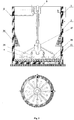
- the filter is equipped with a vibration aerator 20, which is inserted or configured to be inserted into the zigzag channel of the cleaning element lower part of the filtration unit.
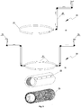
- the vibration aerator can also be made in several forms, for example, in a configuration in which it has a tubular housing 21 in the form of a ring, with holes formed in the central groove extending along the entire length of the internal surface 22, wherein the housing is inserted into the filtering material 23 and elastic material balls 24 are placed in its cavity.
- a with tube 25 for communicating the cavity of the housing with a forced air source or in such a configuration, in which the housing of the vibrating aerator is formed by parts being closed at the end surfaces in the shape of a half ring, each part of the housing being inserted into the similar filtering material and said parts are provided with a separate tube for communicating with a forced air source.
- the filtering material can be made of polyvinyl chloride or any material known from the prior art.
- the filter may also be equipped with a means for providing the airlift vibration. This means can be an air tank 10 fixed on the airlift itself, in which elastic material balls can be placed, or it can be made as a separate element.
- Fig. 6 shows a design feature that can be made as a separate manufactured element between the air tank and the upgraded air tank and which can mainly represent a layout of elastic material balls.
- a rapid filter according to the invention further contains identical structural elements and units, such as filtering medium and filtering unit, according to the invention, comprising a vibration aerator, a cleaning element or an airlift vibration means.
- filtering medium and filtering unit comprising a vibration aerator, a cleaning element or an airlift vibration means.
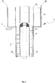
- some units of rapid filters are made and located in the housing in different ways.
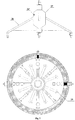
- the liquid distribution unit is located at the bottom, while the sand distribution unit is made as a combination of a directional bevel 26 formed on the internal wall of the housing, a discharge chamber 27 connected to the airlift in its bottom part, and a system 28 of tubes attached thereto, wherein each tube of the system is formed by inclined and vertical parts, the vertical parts of the system tubes being provided with suction means 29.
- Such rapid filters are equipped with a control unit for selectively enabling the operation of the suction means.
- the self-cleaning continuous filter operates as follows: first, the cleaning liquid flows through the tubes to enter the liquid distribution unit, from which it comes in equal flows through perforated holes, a part of the liquid passes through the filtering medium, accumulates in the upper part and flows to the consumer, wherein a part gets into the part of the cone-shaped bottom of the housing, from where it is captured by the airlift and gets into the cleaning element. Due to the airlift vibration, along with the capturing the sand-cleaning liquid into the airlift and its movement, all the positive effects mentioned above are observed.
- the operation principle of the upgraded filter according to the invention is similar to that described above.
- the difference consists in the fact that in this filter the liquid flows from the bottom, the sand distribution unit is made as a combination of two elements, wherein, for example, due to the directional bevel provided in one of them, the sand sinking rate is controlled, and due to the cone-shaped system of tubes provided in the other element, sand distribution at the lower part is achieved.
- the airlift is equipped with two air tanks in accordance with the lifting stages.
- the existence of the control unit provides operation according to a pre-calculated scheme, respectively, the alternate operation of the suction means.
- the vibration of the discharge chamber in general provides the airlift vibration and therefore all the advantages discussed above.
Landscapes
- Chemical & Material Sciences (AREA)
- Chemical Kinetics & Catalysis (AREA)
- Filtration Of Liquid (AREA)
- Biological Treatment Of Waste Water (AREA)
Applications Claiming Priority (1)
| Application Number | Priority Date | Filing Date | Title |
|---|---|---|---|
| GEAP201714632A GEP20186912B (en) | 2017-11-22 | 2017-11-22 | Constructively combined node for nonpressure sandy filters and said filters equipped therewith |
Publications (2)
| Publication Number | Publication Date |
|---|---|
| EP3488910A2 true EP3488910A2 (de) | 2019-05-29 |
| EP3488910A3 EP3488910A3 (de) | 2019-08-07 |
Family
ID=63964128
Family Applications (1)
| Application Number | Title | Priority Date | Filing Date |
|---|---|---|---|
| EP18207891.5A Withdrawn EP3488910A3 (de) | 2017-11-22 | 2018-11-22 | Vorrichtung zur reinigung eines fluids mittels eines filterbetts |
Country Status (3)
| Country | Link |
|---|---|
| EP (1) | EP3488910A3 (de) |
| GE (1) | GEP20186912B (de) |
| RU (1) | RU2018141206A (de) |
Cited By (2)
| Publication number | Priority date | Publication date | Assignee | Title |
|---|---|---|---|---|
| CN109173363A (zh) * | 2018-11-12 | 2019-01-11 | 新乡市绿丰环保工程有限公司 | 连续式活性炭过滤装置及其运行方法 |
| CN116139556A (zh) * | 2023-02-22 | 2023-05-23 | 西安建筑科技大学 | 一种雨水调蓄池前轻质滤料环形过滤装置 |
Family Cites Families (2)
| Publication number | Priority date | Publication date | Assignee | Title |
|---|---|---|---|---|
| JPS5814914A (ja) * | 1981-07-17 | 1983-01-28 | Tsukishima Kikai Co Ltd | 濾過器洗浄部の汚泥付着防止装置 |
| US7897040B2 (en) * | 2007-09-19 | 2011-03-01 | Blue Water Technologies, Inc. | Washbox |
-
2017
- 2017-11-22 GE GEAP201714632A patent/GEP20186912B/en unknown
-
2018
- 2018-11-22 EP EP18207891.5A patent/EP3488910A3/de not_active Withdrawn
- 2018-11-22 RU RU2018141206A patent/RU2018141206A/ru not_active Application Discontinuation
Non-Patent Citations (1)
| Title |
|---|
| None |
Cited By (2)
| Publication number | Priority date | Publication date | Assignee | Title |
|---|---|---|---|---|
| CN109173363A (zh) * | 2018-11-12 | 2019-01-11 | 新乡市绿丰环保工程有限公司 | 连续式活性炭过滤装置及其运行方法 |
| CN116139556A (zh) * | 2023-02-22 | 2023-05-23 | 西安建筑科技大学 | 一种雨水调蓄池前轻质滤料环形过滤装置 |
Also Published As
| Publication number | Publication date |
|---|---|
| GEP20186912B (en) | 2018-10-25 |
| EP3488910A3 (de) | 2019-08-07 |
| RU2018141206A (ru) | 2020-05-22 |
Similar Documents
| Publication | Publication Date | Title |
|---|---|---|
| CN104147842B (zh) | 一种复合型多功能过滤装置 | |
| CN204689650U (zh) | 一种污水处理器 | |
| KR102348752B1 (ko) | 다수의 영역으로 분할된 여과공간을 갖는 비점오염원 저감장치 | |
| EP3488910A2 (de) | Vorrichtung zur reinigung eines fluids mittels eines filterbetts | |
| KR100714178B1 (ko) | 유동형 처리수 배출장치 | |
| CN201253505Y (zh) | 一种气提式连续砂滤装置 | |
| CN116621389A (zh) | 一种高浓污水多级净化处理系统 | |
| CN106946391A (zh) | 一种可快速过滤污水的污水处理装置 | |
| KR100949058B1 (ko) | 여과장치 | |
| CN206526559U (zh) | 一种上流式自清洗过滤器 | |
| KR101784886B1 (ko) | 분배챔버를 이용한 연속여과장치 | |
| CN201501818U (zh) | 催化氧化高效过滤器 | |
| KR20040058088A (ko) | 자동 역세 사여과기 | |
| CN108654155B (zh) | 一种活性砂过滤器 | |
| KR102069531B1 (ko) | 역세형 다층여과 필터 및 이를 이용한 여과방법 | |
| CN103182207B (zh) | 一种采用软质弹性外壁的可膨胀式滤池 | |
| CN204973191U (zh) | 一种多级布水多仓室连续流砂过滤装置 | |
| CN203379652U (zh) | 压力式连续流过滤器 | |
| CN204434354U (zh) | 一种用于降解工业污水的动态膜生物反应器 | |
| US2327726A (en) | Filter bed cleaning | |
| CN113877257A (zh) | 一种水厂滤池钢筋混凝土结构 | |
| KR101269582B1 (ko) | 액상화 현상을 이용한 모래 여과 장치 및 방법 | |
| CN203886254U (zh) | 除盐水预处理系统用生物流砂过滤器 | |
| CN102124984A (zh) | 大型观赏鱼缸 | |
| KR101350585B1 (ko) | 수처리 장치 |
Legal Events
| Date | Code | Title | Description |
|---|---|---|---|
| PUAI | Public reference made under article 153(3) epc to a published international application that has entered the european phase |
Free format text: ORIGINAL CODE: 0009012 |
|
| STAA | Information on the status of an ep patent application or granted ep patent |
Free format text: STATUS: THE APPLICATION HAS BEEN PUBLISHED |
|
| AK | Designated contracting states |
Kind code of ref document: A2 Designated state(s): AL AT BE BG CH CY CZ DE DK EE ES FI FR GB GR HR HU IE IS IT LI LT LU LV MC MK MT NL NO PL PT RO RS SE SI SK SM TR |
|
| AX | Request for extension of the european patent |
Extension state: BA ME |
|
| PUAL | Search report despatched |
Free format text: ORIGINAL CODE: 0009013 |
|
| AK | Designated contracting states |
Kind code of ref document: A3 Designated state(s): AL AT BE BG CH CY CZ DE DK EE ES FI FR GB GR HR HU IE IS IT LI LT LU LV MC MK MT NL NO PL PT RO RS SE SI SK SM TR |
|
| AX | Request for extension of the european patent |
Extension state: BA ME |
|
| RIC1 | Information provided on ipc code assigned before grant |
Ipc: B01D 24/46 20060101ALI20190701BHEP Ipc: B01D 24/30 20060101AFI20190701BHEP |
|
| STAA | Information on the status of an ep patent application or granted ep patent |
Free format text: STATUS: THE APPLICATION HAS BEEN WITHDRAWN |
|
| 18W | Application withdrawn |
Effective date: 20200207 |