EP3488051B1 - Oberflächenmontierte sicherheitsbarriere - Google Patents
Oberflächenmontierte sicherheitsbarriere Download PDFInfo
- Publication number
- EP3488051B1 EP3488051B1 EP17746040.9A EP17746040A EP3488051B1 EP 3488051 B1 EP3488051 B1 EP 3488051B1 EP 17746040 A EP17746040 A EP 17746040A EP 3488051 B1 EP3488051 B1 EP 3488051B1
- Authority
- EP
- European Patent Office
- Prior art keywords
- barrier
- cable
- post
- steel
- concrete block
- Prior art date
- Legal status (The legal status is an assumption and is not a legal conclusion. Google has not performed a legal analysis and makes no representation as to the accuracy of the status listed.)
- Active
Links
Images




Classifications
-
- E—FIXED CONSTRUCTIONS
- E01—CONSTRUCTION OF ROADS, RAILWAYS, OR BRIDGES
- E01F—ADDITIONAL WORK, SUCH AS EQUIPPING ROADS OR THE CONSTRUCTION OF PLATFORMS, HELICOPTER LANDING STAGES, SIGNS, SNOW FENCES, OR THE LIKE
- E01F15/00—Safety arrangements for slowing, redirecting or stopping errant vehicles, e.g. guard posts or bollards; Arrangements for reducing damage to roadside structures due to vehicular impact
- E01F15/02—Continuous barriers extending along roads or between traffic lanes
- E01F15/08—Continuous barriers extending along roads or between traffic lanes essentially made of walls or wall-like elements ; Cable-linked blocks
- E01F15/081—Continuous barriers extending along roads or between traffic lanes essentially made of walls or wall-like elements ; Cable-linked blocks characterised by the use of a specific material
- E01F15/083—Continuous barriers extending along roads or between traffic lanes essentially made of walls or wall-like elements ; Cable-linked blocks characterised by the use of a specific material using concrete
-
- E—FIXED CONSTRUCTIONS
- E01—CONSTRUCTION OF ROADS, RAILWAYS, OR BRIDGES
- E01F—ADDITIONAL WORK, SUCH AS EQUIPPING ROADS OR THE CONSTRUCTION OF PLATFORMS, HELICOPTER LANDING STAGES, SIGNS, SNOW FENCES, OR THE LIKE
- E01F13/00—Arrangements for obstructing or restricting traffic, e.g. gates, barricades ; Preventing passage of vehicles of selected category or dimensions
- E01F13/02—Arrangements for obstructing or restricting traffic, e.g. gates, barricades ; Preventing passage of vehicles of selected category or dimensions free-standing; portable, e.g. for guarding open manholes ; Portable signs or signals specially adapted for fitting to portable barriers
- E01F13/028—Flexible barrier members, e.g. cords; Means for rendering same conspicuous; Adapted supports, e.g. with storage reel
-
- E—FIXED CONSTRUCTIONS
- E01—CONSTRUCTION OF ROADS, RAILWAYS, OR BRIDGES
- E01F—ADDITIONAL WORK, SUCH AS EQUIPPING ROADS OR THE CONSTRUCTION OF PLATFORMS, HELICOPTER LANDING STAGES, SIGNS, SNOW FENCES, OR THE LIKE
- E01F13/00—Arrangements for obstructing or restricting traffic, e.g. gates, barricades ; Preventing passage of vehicles of selected category or dimensions
- E01F13/12—Arrangements for obstructing or restricting traffic, e.g. gates, barricades ; Preventing passage of vehicles of selected category or dimensions for forcibly arresting or disabling vehicles, e.g. spiked mats
-
- E—FIXED CONSTRUCTIONS
- E01—CONSTRUCTION OF ROADS, RAILWAYS, OR BRIDGES
- E01F—ADDITIONAL WORK, SUCH AS EQUIPPING ROADS OR THE CONSTRUCTION OF PLATFORMS, HELICOPTER LANDING STAGES, SIGNS, SNOW FENCES, OR THE LIKE
- E01F15/00—Safety arrangements for slowing, redirecting or stopping errant vehicles, e.g. guard posts or bollards; Arrangements for reducing damage to roadside structures due to vehicular impact
- E01F15/02—Continuous barriers extending along roads or between traffic lanes
- E01F15/06—Continuous barriers extending along roads or between traffic lanes essentially made of cables, nettings or the like
Definitions
- the present invention relates to a security barrier section, a security barrier and a security barrier island, in particular for use in a surface mounted security barrier to prevent vehicular penetration.
- Security barriers or crash barriers, the main purpose of which being to prevent the passage of vehicles, are widely known in the art and have many applications. Common applications are for bordering dangerous sections of roads, providing a central separation between lanes of traffic moving in opposite directions, and around secure areas, for example around the entrance to airports or the like.
- Known security barriers are generally made of metals, in particular steel, and comprise a post, which is bedded in concrete, and to which a barrier is attached.
- a barrier is attached to provide the structural integrity to stop a car moving at around 40 to 50 km/h (about 25 to 30 mph)
- such barriers need a very deep, reinforced bedding of around a meter in depth and, for larger trucks, a bedding of up to two meters, into which the posts are set.
- the necessity of burying the posts to such a depth often interferes with existing buried services, for example electricity cables and sewage or water pipes.
- US 5 676 350 discloses a portable barrier system including a portable post support device having a base member with a handle and an attachment mechanism for supporting a post, the post in turn supporting a barrier material.
- the post support is a concrete block having an internal metal structure for receiving a post.
- this barrier would not be sufficient to stop a vehicle moving at speed.
- a security barrier section for preventing vehicular penetration, comprising: first and second barrier islands, each said island comprising: a cast concrete block having a front face and a rear face, said front and rear faces being faces of the concrete block that are substantially parallel to the direction along which the security barrier runs; a spring steel post extending upwardly from a top face of the cast concrete block at a location between the front face and the rear face; and attachment means located on, or extending from, at least one of the front face and the rear face; at least one first cable extended between the spring steel posts of said first and second barrier islands and attached thereto by first cable attachments; at least one second cable extended between the attachment means of said first and second barrier islands and attached thereto by second cable attachments; wherein said first and second cable attachments are configured to allow said cable to slip in said cable attachment under loading.
- the at least one first cable may comprise a plurality of cables extending between the spring steel posts.
- the vehicle substantially then acts as an anchor for the barrier section in the immediate locality of the impact and prevents the force of the collision from causing the barrier section islands to become airborne. Once a barrier becomes airborne it usually suffers catastrophic failure, has little further resistance and, as such, cannot prevent vehicular penetration.
- front and rear face are used to denote the faces of the concrete block that are substantially parallel to the direction along which the security barrier section runs.
- the security barrier section is designed to protect against a vehicle impacting from the direction of the front or rear face to which the second cable is attached. It will also be understood that in embodiments having a second cable on both of the front and the rear faces the design is substantially symmetrical and therefore offers protection from an impact in both directions, i.e. from a direction of the front face or the direction of the rear face.
- the barrier of the invention has the advantage that it can be quickly installed without the need for permanent attachment or to be embedded in the surface on which it is located and under impact the ability for the first and second cables to slip enables a small proportion of the initial energy of impact to be absorbed prior to the post and the block to which the cables are attached experiencing the full impact of the collision, thereby reducing loading on these parts.
- the at least one first and at least one second cable each may comprise a stop at either end thereof and wherein the extent of slip of said at least one cable in said attachment is limited by said stops.
- a loop may be formed in at least one end of the at least one first cable, and the loop passes over the spring steel post of said first and second barrier islands, said loop forming said stop.
- the loop may be formed in at least one end of the at least one second cable, and the loop passes over the attachment means of said first and second barrier islands, said loop forming said stop.
- the attachments may comprise clamps which clamp the at least one first cable against the spring steel posts of the first and second barrier islands, and which clamp the at least one second cable against the attachment means of the first and second barrier islands.
- the clamps may comprise one or more U-bolts passing through holes provided in said spring steel posts and in said attachment means.
- the security barrier section comprises said attachment means on the front and rear face, optionally two attachment means are provided on said front and/or said rear face.
- the at least one second cable may comprise a second cable extended between the attachment means on the front faces of said first and second barrier islands and a second cable extended between the attachment means on the rear faces of said first and second barrier islands.
- the attachment means comprises a spring steel attachment post extending from at least one of said front and said rear face
- the attachment post may be a spring steel post.
- each cast concrete block may comprise at least one opening extending there through and opening onto the front face and the rear face, said opening for receiving said steel attachment post there through such that it extends from either end thereof.
- the at least one opening may comprise a steel tubular member extending from said front face to said rear face, said steel tube being cast into said concrete block.
- spring steel for the attachment post ensures that under impact some of the forces acting on it from the second cable(s) is dissipated within the attachment post which, being spring steel will undergo elastic deformation rather than the plastic deformation that would be experienced if standard steel were used.
- each cast concrete block comprises a steel post footing cast therein which opens onto a top face thereof.
- the steel post footing comprises a substantially vertical tubular member for receiving said spring steel post therein. This enables the concrete blocks to be arranged in a compact manner for transportation without the spring steel post extending therefrom.
- each said cast concrete block further comprises a plurality of fence post recesses located adjacent the front and/or rear face, each said fence post recess comprising a substantially vertical tubular steel member embedded in each said cast concrete block and opening onto top face thereof.
- a fence post may be located in each said fence post recess and such that it extends substantially vertically therefrom.
- a fence panel may be attached to said fence posts.
- the barrier section further comprises a plurality of fence support members and said fence panel is attached to the fence support members and each said fence support member is attached to a fence post.
- each cast concrete block comprises a rebar cage comprising a first and second plurality of substantially rectangular rebar sections arranged substantially perpendicularly to each other, said rebar cage encased in said concrete block.
- the security barrier section may comprise an intermediate barrier island comprising a cast concrete block and a cable support post extending therefrom, said intermediate barrier island located between said first and second barrier islands, and wherein said at least one first cable is attached to said cable support post.
- a security barrier comprising a plurality of security barrier sections according to another aspect of the invention, and wherein adjacent security barrier sections share a common barrier island.
- the attachment means may comprise U-bolts passing through said spring steel posts and the at least one first cables of adjacent security barrier sections may share common U-bolts.
- at least one common barrier island constitutes a corner island arranged between two adjacent barrier sections, the two adjacent barrier sections meeting at an included angle of less than 180°.
- a barrier island for a security barrier to prevent vehicular penetration comprising: a cast concrete block having a front face and a rear face, said front and rear faces being faces of the concrete block that are substantially parallel to the direction along which the security barrier is intended to run, and surrounding a steel structure; a spring steel post extending upwardly from a top face of the cast concrete block at a location between the front face and the rear face for, in use, attaching at least one first cable thereto by first cable attachments such that the first cable can slip in said first cable attachments under loading; and attachment means located on, or extending from, at least one of the front face and the rear face of said cast concrete block for, in use, attaching at least one second cable thereto by second cable attachments such that the second cable can slip in said second cable attachments under loading.
- the steel structure further comprises: first and second steel tubular members each arranged to extend from the front face to the rear face and opening at said respective front and rear faces, said first and second steel tubular members for receiving said attachment means; a steel post footing comprising a substantially vertical steel tubular member opening onto and extending downwardly from the top face, said steel post footing receiving said spring steel post therein; and a rebar cage comprising a first and second plurality of substantially rectangular rebar sections arranged substantially perpendicularly to each other.
- the steel structure may also comprise one or more of: a plurality of fence post recesses located adjacent the front and/or rear face, each said fence post recess comprising a substantially vertical tubular steel member opening onto said top face of the cast concrete block; and a plurality of attachment points each comprising a threaded steel member said threaded steel members located such that they open onto, or extend from, the top face of the cast concrete block.
- the security barrier section 10 comprises first and second barrier islands 12, 14 each of which comprise a cast concrete block 16 having a front face 18 and a rear face 20.
- the security barrier islands are designed to be simply placed on the surface where a security barrier is needed, i.e. they provide a surface mount security barrier that does not need to be located in an excavated trench and does not need to be attached to the surface.
- the concrete block 16 is described in more detail with reference to Figures 2 and 3 below.
- a spring steel post 22 extends upwardly from a top face 24 of the cast concrete block 16 at a location between the front face and the rear face. As can be seen in the example embodiment the spring steel post 22 is located substantially in the centre of the concrete block 16. The exact location of the spring steel post 22 is not critical providing that it is spaced from either the front or the rear face, whichever is, in use, intended to face the direction from which it is designed to receive an impact for reasons that will be described in detail below. In the example embodiment it is an advantage of locating the spring steel post 22 substantially in the centre of the concrete block 16 in that a substantially symmetric barrier island 12, 14 is created. By providing a symmetrical barrier island the installation is simplified in that the concrete blocks 16 can be placed in either orientation without detriment to the performance of the barrier.
- the spring steel post is located at a position which is a minimum of 500mm from the front/rear face of the concrete block 16.
- the distance from the front face to the rear face is 1200mm and the spring steel post 22 is located equidistance from face.
- a pair of attachment means 26 extends from the front face 18 and the rear face 20 of the concrete block 16.
- an individual cable 30, which may be referred to as a second cable extends between the attachment means 26 of the first and second barrier islands on each of the front faces and the rear faces thereof.
- the first 28 and second 30 cables are attached to the spring steel posts 22 and the attachment means 26 by respective first and second cable attachments 32 which are configured to allow said cable to slip therein under loading.
- the cable attachments 32 comprise U-bolts which clamp the first cables 28 against the spring steel posts 22 of said first and second barrier islands, and which clamp the at least one second cable 30 against the attachment means 26 of said first and second barrier islands.
- the U-bolts 32 pass through holes provided in said spring steel posts 22 and in the attachment means 26 and have a plate on their opposite face against which the nuts of the U-bolt 32 are tightened thereby forming a clamp.
- the embodiment described herein has three first cables, and a single second cable on each side thereof, it will be appreciated that different numbers of first cables and second cables may be used.
- first and second cables may be varied, in particular they may vary in dependence on the sped of impact which the barrier is intended to withstand.
- a loop is formed in each end of the cables 28, 30, which pass over the spring steel posts 22 and the attachment means 26, of the first and second barrier islands. In use the loop forms a stop to limit the extent to which the cables 28, 30 may slip in the cable attachments 32 under impact.
- the arrangement of the loops of the first cables 28 will be understood by reference to WO2015033100 , in particular Figures 12 and 13.
- the attachment means 26 are located at a position in the range of up to a maximum of 400mm, preferably less than 350mm, and in the preferred embodiment in range of 200mm to 300mm, above a bottom face of the cast concrete block 16, such that in use the second cables 30 extending therefrom are maintained at a height of upto 400mm above the surface on which the barrier section is placed.
- an intermediate barrier island 54 can be provided between the first and second barrier islands.
- the intermediate barrier island comprises a cast concrete block 16A and a cable support post 22A extending therefrom.
- the first cables 28 are attached, approximately at their mid points, to the cable support post 22A.
- the second cables may also be attached to the intermediate barrier islands.
- the intermediate barrier islands 54 can be smaller than the first 12 and second 14 barrier island and prevent the cables from sagging at their mid points, thereby enabling a greater distance between the first 12 and second 14 barrier islands.
- the concrete blocks 16A of the intermediate barrier islands 54 may have a substantially similar structure as the concrete blocks 16 of the barrier islands 12, 14, albeit they may be dimensionally smaller and the post footing (see below) may be dimensioned to receive a substantially smaller post 22A.
- the concrete block 16 comprises an internal steel structure 34 that is substantially enclosed in concrete. It will be understood that the concrete blocks 16 are pre-cast concrete blocks that are preferably prefabricated and transported to their place of installation, however it is to be understood that the cast concrete blocks could also be cast on location prior to being formed into a barrier.
- the steel structure 34 comprises a rebar cage comprising a first 36 and second 38 plurality of substantially rectangular rebar sections arranged substantially perpendicularly to each other.
- a steel foot box 40 Centrally located in the steel structure is a steel foot box 40 which comprises a vertical tubular section 42 attached to a base plate 44 and supported thereon by a plurality of ribs 46.
- the steel foot box 40 receives the spring steel post 22 therein.
- the tubular section 42, base plate 44 and ribs 46 are welded together to make a single structure 40.
- the steel structure 34 also includes first and second attachment means receivers 48, each of which comprise a steel tubular members, e.g. a section of steel box section, that extends in a direction from the front face to the back face of the concrete block 16.
- first and second attachment means receivers 48 each for receive an attachment means 26 therein in a manner that they extend from the front and rear face of the concrete block.
- the attachment means 26 that are received in each attachment means receiver 48 each comprise a spring steel member with a pair of holes in either end thereof for receiving the U-bolts.
- each attachment means receiver 48 has an internal width of at least 120mm and each attachment means receivers 48 are spaced at an internal spacing in the region of 1000mm to 1500mm. These dimensions can enable a fork lift truck to insert its forks into the attachment means receivers 48 to easily lift and move the cast concrete blocks 16.
- the attachment means 26 comprising a spring steel member with a pair of holes in either end thereof may form part of the steel structure 34 in place of the attachment means receivers 48 such that they are cast into the concrete block 16.
- the steel structure of the example embodiment shown in the Figures 3 and 4 also includes some optional additional features.
- the steel structure 34 includes an of attachment point, each comprising a threaded steel member 50, which may be a male or female threaded member, located substantially in each of the four upper corners in a position that, once the concrete block 16 is cast around the steel structure 34 open onto, or extend from, the top face 24 of the cast concrete block 16.
- Each threaded steel member 50 is attached to a steel anchoring plate 52 that assists in securing the attachment points in the concrete bock.
- lifting attachments can easily be attached to the threaded members 50 such that the concrete blocks 16 can easily be lifted by an overhead lifting machine, for example a crane or hoist.
- a further optional feature that is included in the example embodiment is the inclusion, in the steel structure 34, of a plurality of fence post recesses 56 located adjacent the front and/or rear face, each said fence post recess comprising a substantially vertical tubular steel member 58.
- the fence post recesses 56 receive a fence post such that a fence can be attached to the concrete blocks.
- a fence post recess 56 is provided substantially in each corner of the concrete block such that a fence panel can be provided adjacent each of the front 18 and the rear 20 faces of the barrier section.
- All of the components of the steel structure may be welded or brazed together to form a unitary structure 36 which is then either placed in a mould, or shuttering is assembled therearound and concrete is poured around the structure to substantially surround it.
- the mould/shuttering is dimensioned such that the foot box 40, the threaded members 50, and the fence post recesses 56 open substantially onto the top face 24 of the concrete block 16 and the attachment means receivers 48 open onto the front 18 and rear 20 faces of the concrete block 16.
- the concrete block is dimensioned 2000mm x 1200mm x 600mm (+/- 50mm).
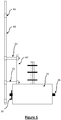
- a barrier section 10 having a fence post 60 located in each said fence post recess 56 and extending substantially vertically therefrom. Attached at one end to each fence post 60 is a pair of fence spacers 62. The fence spacers are each attached at their other end to a fence support member 64 to which a fence panel 68 is attached. By means of the fence support member 64 and the fence spacers 62 the fence panel 68 is attached to the fence posts 60 located in the fence post recesses 56 of each barrier island.
- the fence panel 60 could be attached directly to the fence posts the described arrangement enables the fence panels to be located forward of the concrete blocks 16 and attached second cables 30 so that they do not interfere therewith.
- Additional longitudinal fence braces 65 are provided extending between the fence posts of adjacent concrete blocks. Although shown without an intermediate barrier island, it will be appreciated that the intermediate barrier island, when used, can be provided with the same of a similar arrangement to provide further fence support structures.
- the fence panel 68 may be attached by means of simple U-bolts 69 or other easily attachable and releasable connectors, for example zip ties.
- Figure 6 shows a side view similar to that of Figure 5 except in that fence posts 60, spacers 62 and fence support members 64 are provided on both sides thereof 60, and to effect a symmetrical barrier. This design enables a fence to quickly be erected on the concrete blocks 16 that can then provide a single, or double, pedestrian barrier as well as a vehicular barrier.
- the security barrier comprises a number of the security barrier sections 10 connected together such that adjacent security barrier sections share a common barrier section island 14.
- the U-bolts passing through the spring steel post 22 of the common barrier section island 14 are shared U-Bolts common to the first cables 28 from the adjacent barrier sections.
- the common barrier island 14 may constitutes a corner island arranged between two adjacent barrier sections, the two adjacent barrier sections meeting at an included angle of less than 180.
- the barrier is installed as follows. Approximately 6 meter centres are marked on the ground along the intended line the barrier and barrier islands 12, 14 and intermediate barrier islands 54 are placed on alternate centre marks. This is repeated along the run of the barrier and a barrier island 12, 14 is placed on the final centre mark. Next the spring steel posts 22 are inserted into the foot boxes 40 of the barrier islands 12, 14 and the cable support posts 22A are inserted into the foot box of the intermediate barrier islands 54. The posts may be secured in place in the foot box 40 by using pieces of packing material (which may be in the form of steel shims or the like) and additionally grout may be applied around the posts 22, 22A. Although described as being done in situ, it will be appreciated that the barrier islands may be transported to the site of the barrier with the spring steel posts 22 already in place in the foot boxes 40
- the spring steel members of the attachment means 26 are located through the attachment means receivers 48 so that they extend from either side thereof, and are secured in place by the use of pieces of packing material. This is preferably done on site so that the barrier islands can be closely packed in transit with reduced risk of damage from or to the attachment means 26.
- the second cables 30 are then located over the protruding end of the first spring steel member of the attachment means 26 of the first barrier island, across the front face of the barrier island 12 and under the second spring steel member of the attachment means.
- the cable 28 is then attached to the second barrier island 14 in a symmetrical manner, i.e. passing under the first attachment means 26 thereof and looping over the second attachment means 26 thereof. In between the first 12 and second 14 barrier islands, the second cables 30 pass under the attachment means of the intermediate barrier island 54.
- the cables 30 could pass over the attachment means 26 so that the weight of the cable will be supported until it is attached. This, however, this will be at the detriment of force distribution during an impact.
- the second cables 30 are then clamped to each of the attachment means 26 by use of U-bolts.
- the ends of the cables 30 are tensioned such that a there is a gap between the end of loop in the cable and the attachment means such that under impact the cable undergo a limited amount of slip until the end of the loop abuts the attachment means, thereby preventing any further slip through the U-bolts.
- the U-bolts are torqued to 14.12Nm (125Lb/Inch).
- first cables 28 are fitted to the spring steel posts 22.
- the lower cables are fitted first along the full run of the barrier and then the sequentially higher cables ones, again along the complete run.
- a first looped end of the cable 28 is placed over the spring steel post 22, a U-Bolt is pushed through holes in the post at the attachment position to loosely attach the cable to the post.
- This is then repeated at the second end of the cable 30.
- the cable is the pulled such that there is a gap between the end of the loop and the post 22 and the U-bolt at the first end is then tightened. This is then repeated at subsequent posts 22 along the run of the barrier.
- both cables will need to be in situ and the U-bolts tensioned such that there is gap between the ends of the loops of both cables and the post 22.
- This arrangement is shown in WO2015033100 as mentioned above.
- the gap between the ends of the loops of the cables 28 and the posts 22 is over 60mm, preferably in the range of 60-100mm, although it will be appreciated that a bigger gap can be employed if necessary to tighten the cable.
- tensioning or tightening the cables is not intended to imply that the cables 28, 30 are under a high tension, the tensioning is merely intended to result in maintaining the cables at the required height with minimal amount of sag there between.
- U-bolts are used to attach the cables 28 to the cable support posts 22A of the intermediate barrier islands 54 to support them and reduce any sag at their mid-point.
- the U-bolts are initially tightened to a torque of approximately 7.34Nm (65lb/in) and once the cables have been checked to ensure that they are at the appropriate position on the cable support posts the U-bolts can be fully tightened to a torque off 125lb/inch.
- the fence posts 60, fence spacers 62, fence support members 64 and fence panels 68 as described above with reference to Figures 4 to 6 can then be assembled onto the security barrier 100.
- FIG. 8 an example embodiment of the end of a security barrier 100A is shown which is designed to withstand a high speed impact force.
- additional barrier islands 12A may be daisy chained together by means of attaching the second cables 30 to the attachment means 26 of each said additional barrier islands 12A, such they extend from the end barrier island 12 of the barrier in the direction of the first intermediate island 54.
- an additional first cable 28 is used.
- the attacking vehicle will have run over the second cables 30 fixed to the concrete blocks 16 and will be under the vehicle. This in effect anchors the concrete blocks 16 to the vehicle and prevents them from becoming airborne.
- the second cables 30 are run underneath he attachment means 26 as the force is directed directly onto the spring steel member of the attachment means 26, which passes through the concrete block 16, by the cable, whereas is they were located on top of the attachment means the U-bolts attaching the cables 30 to the attachment means 26 would become a part of the force transmission path between the vehicle and the mass of the concrete block 16.
- a fence as described herein was set up with the barrier islands freely place on a concrete surface and was tested by a controlled 90° collision with a 7.5 tonne truck, in accordance with BSI-IWA 14-1:2013 testing for vehicle security barriers, and met the requirements of the test in a collision with a 7.5 tonne truck travelling at 30mph.
- the bollard described herein is, to the inventors knowledge, the world's first freestanding surface mount fence to pass this test.
Landscapes
- Engineering & Computer Science (AREA)
- Architecture (AREA)
- Civil Engineering (AREA)
- Structural Engineering (AREA)
- Aviation & Aerospace Engineering (AREA)
- Refuge Islands, Traffic Blockers, Or Guard Fence (AREA)
Claims (15)
- Sicherheitsbarrierenabschnitt (10) zum Verhindern des Einfahrens von Fahrzeugen, umfassend:eine erste (12) und eine zweite (14) Barriereinsel, wobei jede der Inseln umfasst:einen Gussbetonblock (16) mit einer Vorderseite (18) und einer Rückseite (20), wobei die Vorder- und Rückseite Seiten des Betonblocks sind, die im Wesentlichen parallel zu der Richtung sind, entlang der der Sicherheitsbarrierenabschnitt verläuft; einen Federstahlpfosten (22), der sich von einer Oberseite (24) des Gussbetonblocks an einer Stelle zwischen der Vorderseite und der Rückseite nach oben erstreckt; und Befestigungsmittel (26), die sich an der Vorderseite (18) und/oder der Rückseite (20) befinden oder sich von diesen erstrecken;mindestens ein erstes Kabel (28), das sich zwischen den Federstahlpfosten (22) der ersten und der zweiten Barriereinsel (12, 14) erstreckt und an diesen durch erste Kabelbefestigungen befestigt ist;mindestens ein zweites Kabel (30), das sich zwischen den Befestigungsmitteln (26) der ersten und zweiten Barriereinsel erstreckt und daran durch zweite Kabelbefestigungen (32) befestigt ist;wobei die erste und die zweite Kabelbefestigung (32) so konfiguriert sind, dass das Kabel (28, 30) unter Belastung in der Kabelbefestigung (32) verrutschen kann.
- Sicherheitsbarrierenabschnitt (10) nach Anspruch 1, wobei das mindestens eine erste (28) und das mindestens eine zweite (30) Kabel jeweils einen Anschlag an einem seiner Enden umfasst und wobei das Ausmaß des Verrutschens des mindestens einen Kabels in der Befestigung durch die Anschläge begrenzt ist, und wobei:eine Schlaufe in mindestens einem Ende des mindestens einen ersten Kabels (28) gebildet ist und die Schlaufe über den Federstahlpfosten (22) der ersten und zweiten Barriereinsel (12, 14) verläuft, wobei die Schlaufe den Anschlag bildet und/oderwobei eine Schlaufe in mindestens einem Ende des mindestens einen zweiten Kabels (30) gebildet ist und die Schlaufe über die Befestigungsmittel (26) der ersten und zweiten Barriereinsel (12, 14) verläuft, wobei die Schlaufe den Anschlag bildet.
- Sicherheitsbarrierenabschnitt (10) nach Anspruch 1 oder Anspruch 2, wobei die Befestigungen (32) Klemmen umfassen, die das mindestens eine erste Kabel (28) gegen die Federstahlpfosten (22) der ersten und zweiten Barriereinsel (12, 14) klemmen und die das mindestens eine zweite Kabel (30) gegen die Befestigungsmittel (26) der ersten und zweiten Barriereinsel (12, 14) klemmen.
- Sicherheitsbarrierenabschnitt (10) nach einem der vorhergehenden Ansprüche, umfassend zwei Befestigungsmittel (32) an der Vorderseite und/oder Rückseite.
- Sicherheitsbarrierenabschnitt nach Anspruch 4, umfassend die Befestigungsmittel an der Vorderseite und der Rückseite, wobei das mindestens eine zweite Kabel (30) ein zweites Kabel umfasst, das sichzwischen den Befestigungsmitteln (32) an der Vorderseite (18) der ersten und zweiten Barriereinsel (12, 14) erstreckt,und ein zweites Kabel (30), das sich zwischen den Befestigungsmitteln (32) an den Rückseiten (20) der ersten und zweiten Barriereinsel (12, 14) erstreckt.
- Sicherheitsbarrierenabschnitt (10) nach einem der vorhergehenden Ansprüche, wobei die Befestigungsmittel (32) einen Stahlbefestigungspfosten umfassen, der sich von der Vorder- (18) und/oder Rückseite (20) aus erstreckt, und wobei jeder Gussbetonblock (16) mindestens eine Öffnung (48) umfasst, die sich durch ihn hindurch erstreckt und sich auf der Vorderseite und der Rückseite öffnet, wobei die Öffnung (48) zur Aufnahme des Stahlbefestigungspfostens durch sie hindurch so beschaffen ist, dass sie sich von jedem Ende davon aus erstreckt.
- Sicherheitsbarrierenabschnitt (10) nach einem der vorhergehenden Ansprüche, wobei jeder Gussbetonblock (16) ein darin eingegossenes Stahlpfostenfundament (40) umfasst, das auf einer Oberseite (24) desselben offen ist, wobei das Stahlpfostenfundament (40) ein im Wesentlichen vertikales Rohrelement zur Aufnahme des Federstahlpfostens (22) darin umfasst.
- Sicherheitsbarrierenabschnitt (10) nach einem der vorhergehenden Ansprüche, wobei jeder Gussbetonblock (16) ferner mehrere Zaunpfostenaussparungen (56) umfasst, die angrenzend an die Vorderseite und/oder die Rückseite angeordnet sind, wobei jede Zaunpfostenaussparung (56) ein im Wesentlichen vertikales Stahlrohrelement umfasst, das in jeden Gussbetonblock (16) eingebettet ist und sich auf dessen Oberseite (24) öffnet.
- Sicherheitsbarrierenabschnitt (10) nach Anspruch 8, ferner umfassend einen Zaunpfosten (64), der sich in jeder Zaunpfostenaussparung (56) befindet und sich im Wesentlichen vertikal davon erstreckt, und ferner umfassend eine Zaunplatte (68), die an den Zaunpfosten (64) befestigt ist.
- Sicherheitsbarrierenabschnitt (10) nach einem der vorhergehenden Ansprüche, ferner umfassend eine Zwischenbarriereinsel (54), die einen Gussbetonblock (16A) und einen sich davon erstreckenden Kabeltragpfosten (22A) umfasst, wobei die Zwischenbarriereinsel (54) zwischen der ersten und der zweiten Barriereinsel (12, 14) angeordnet ist und wobei das mindestens eine erste Kabel (28) an dem Kabeltragpfosten (22A) befestigt ist.
- Sicherheitsbarriere (100), umfassend mehrere Sicherheitsbarrierenabschnitte (10) nach einem der vorhergehenden Ansprüche, wobei benachbarte Sicherheitsbarrierenabschnitte (10) eine gemeinsame Barriereinsel teilen.
- Sicherheitsbarriere (100) nach Anspruch 11, wobei die Befestigungsmittel (32) Bügelschrauben umfassen, die durch die Federstahlpfosten (22) hindurchgehen, und wobei die mindestens einen ersten Kabel (28) benachbarter Sicherheitsbarrierenabschnitte (10) gemeinsame Bügelschrauben aufweisen.
- Sicherheitsbarriere (100) nach Anspruch 11 oder 12, wobei mindestens eine gemeinsame Barriereinsel eine Eckinsel darstellt, die zwischen zwei benachbarten Barrierenabschnitten (10) angeordnet ist, wobei sich die beiden benachbarten Barrierenabschnitte (10) in einem eingeschlossenen Winkel von weniger als 180° treffen.
- Barriereinsel (12, 14) für eine Sicherheitsbarriere (100) zum Verhindern des Einfahrens von Fahrzeugen, wobei die Barriereinsel umfasst:einen Gussbetonblock (16) mit einer Vorderseite (18) und einer Rückseite (20), der eine Stahlstruktur (34) umgibt, wobei die Vorder- und Rückseite Seiten des Betonblocks sind, die im Wesentlichen parallel zu der Richtung sind, entlang der die Sicherheitsbarriere verlaufen soll;einen Federstahlpfosten (22), der sich von einer Oberseite (24) des Gussbetonblocks an einer Stelle zwischen der Vorderseite (18) und der Rückseite (20) nach oben erstreckt, um in Gebrauch mindestens ein erstes Kabel (28) durch erste Kabelbefestigungen derart daran zu befestigen, dass das erste Kabel (28) unter Belastung in den ersten Kabelbefestigungen verrutschen kann; undBefestigungsmittel (26), die sich an der Vorderseite (18) und/oder der Rückseite (20) des Gussbetonblocks (16) befinden oder sich von diesen erstrecken, um in Gebrauch mindestens ein zweites Kabel (30) mittels zweiter Kabelbefestigungen (32) derart daran zu befestigen, dass das zweite Kabel (30) unter Belastung in den zweiten Kabelbefestigungen (32) verrutschen kann.
- Barriereinsel (12, 14) nach Anspruch 14, wobei die Stahlstruktur (34) ferner eines oder mehrere der folgenden Elemente umfasst:ein erstes und ein zweites Stahlrohrelement (48), die jeweils so angeordnet sind, dass sie sich von der Vorderseite (18) zur Rückseite (20) erstrecken und sich an der jeweiligen Vorder- und Rückseite öffnen, wobei das erste und das zweite Stahlrohrelement zur Aufnahme der Befestigungsmittel dienen, ein Stahlpfostenfundament (40), das ein im Wesentlichen vertikales Stahlrohrelement (42) umfasst, das sich auf der Oberseite (24) öffnet und sich von dieser nach unten erstreckt, wobei das Stahlpfostenfundament (40) den Federstahlpfosten (22) darin aufnimmt, und einen Bewehrungskäfig, der eine erste (36) und eine zweite (38) Mehrzahl von im Wesentlichen rechteckigen Bewehrungsschnitten umfasst, die im Wesentlichen senkrecht zueinander angeordnet sind; undmehrere Zaunpfostenaussparungen (56), die sich angrenzend an die Vorderseite und/oder Rückseite befinden, wobei jede Zaunpfostenaussparung ein im Wesentlichen vertikales Stahlrohrelement (58) umfasst, das sich auf der Oberseite (24) des Gussbetonblocks (16) öffnet.
Applications Claiming Priority (2)
| Application Number | Priority Date | Filing Date | Title |
|---|---|---|---|
| GB1612876.1A GB2552498B (en) | 2016-07-25 | 2016-07-25 | Surface mount security barrier |
| PCT/EP2017/068699 WO2018019798A1 (en) | 2016-07-25 | 2017-07-24 | Surface mount security barrier |
Publications (2)
| Publication Number | Publication Date |
|---|---|
| EP3488051A1 EP3488051A1 (de) | 2019-05-29 |
| EP3488051B1 true EP3488051B1 (de) | 2021-09-01 |
Family
ID=56894401
Family Applications (1)
| Application Number | Title | Priority Date | Filing Date |
|---|---|---|---|
| EP17746040.9A Active EP3488051B1 (de) | 2016-07-25 | 2017-07-24 | Oberflächenmontierte sicherheitsbarriere |
Country Status (5)
| Country | Link |
|---|---|
| US (1) | US10837148B2 (de) |
| EP (1) | EP3488051B1 (de) |
| AU (1) | AU2017301852B2 (de) |
| GB (1) | GB2552498B (de) |
| WO (1) | WO2018019798A1 (de) |
Families Citing this family (7)
| Publication number | Priority date | Publication date | Assignee | Title |
|---|---|---|---|---|
| GB2566062A (en) * | 2017-09-01 | 2019-03-06 | Gerrard Robert | Surface mount security barrier |
| EP3870763B1 (de) | 2018-10-23 | 2024-12-04 | Guardiar Europe BVBA | Verankerungsvorrichtung für einen zaun und zaun beinhaltend eine solche vorrichtung |
| US12553200B2 (en) | 2019-07-29 | 2026-02-17 | Peter Duncan WHITFORD | Vehicle mitigation systems and methods of deploying a vehicle mitigation system |
| US12031280B1 (en) | 2019-07-29 | 2024-07-09 | Peter Whitford | Barrier system |
| AU2023275395B2 (en) * | 2022-04-28 | 2026-01-29 | Peter Duncan WHITFORD | Vehicle mitigation system |
| AU2023338804A1 (en) | 2022-09-08 | 2025-03-20 | Peter Duncan WHITFORD | Vehicle mitigation system |
| US20240352690A1 (en) * | 2023-04-21 | 2024-10-24 | Black Security Products, LLC | Portable passive cable barrier system |
Family Cites Families (42)
| Publication number | Priority date | Publication date | Assignee | Title |
|---|---|---|---|---|
| US1680548A (en) * | 1927-12-13 | 1928-08-14 | Paul L Keiser | Highway guard |
| US1895670A (en) * | 1932-07-11 | 1933-01-31 | Dayton Malleable Iron Co | Fence post |
| US2007466A (en) * | 1932-08-30 | 1935-07-09 | Colorado Fuel And Iron Company | Highway guard fence |
| US2085058A (en) * | 1934-03-12 | 1937-06-29 | Wood Henry Allyn | Guardrail |
| US2051465A (en) * | 1934-11-20 | 1936-08-18 | American Steel & Wire Co | End connection for flat metal strip guard rails |
| US2204556A (en) * | 1935-07-08 | 1940-06-18 | Carl C Ahles | Road guard |
| US2204557A (en) * | 1935-07-08 | 1940-06-18 | Carl C Ahles | Road guard |
| US2248422A (en) * | 1939-11-18 | 1941-07-08 | American Steel & Wire Co | Road guard assembly |
| US2317249A (en) * | 1942-05-20 | 1943-04-20 | American Steel & Wire Co | Highway guard |
| US2646969A (en) * | 1950-01-07 | 1953-07-28 | Us Spring & Bumper Co Inc | Highway guard |
| US3077339A (en) * | 1961-02-06 | 1963-02-12 | Andrew J White | Yieldable highway guard |
| CH392594A (it) * | 1963-08-10 | 1965-05-31 | Bianchi Mina Ivan Dott | Complesso di barriere protettive e antiabbaglianti per autostrada marginali e spartitraffico atto ad impedire la fuoriuscita di strada degli autoveicoli e a riportarli nella primitiva direzione di marcia |
| US3614844A (en) * | 1970-04-21 | 1971-10-26 | Emery H Withers | Flood gate structure |
| US4681302A (en) * | 1983-12-02 | 1987-07-21 | Thompson Marion L | Energy absorbing barrier |
| GB2188662B (en) * | 1986-04-02 | 1989-11-22 | Glasdon Ltd | Improvements in or relating to barrier members for temporary roadway or pavement barrier systems |
| DE3629935A1 (de) * | 1986-09-03 | 1988-03-10 | Malkmus Doernemann Carola | Zaunanlage |
| GB8708549D0 (en) * | 1987-04-09 | 1987-05-13 | Costelloe J | Barrier |
| CA2106042C (en) * | 1992-09-14 | 1997-01-07 | William G. Krage | Roadside barrier |
| US5387049A (en) * | 1993-06-29 | 1995-02-07 | Barrier Systems, Inc. | Roadway barrier module, system and method |
| US5676350A (en) * | 1994-12-06 | 1997-10-14 | Galli; George | Portable barrier system with portable post mounting device |
| US5651635A (en) * | 1995-04-24 | 1997-07-29 | Schuylkill Products, Inc. | Concrete barrier with reinforcement |
| US5605413A (en) * | 1995-06-26 | 1997-02-25 | Brown; James C. | Highway barricade |
| DE20019889U1 (de) * | 2000-11-22 | 2001-02-01 | Cürten, Wilhelm, 51515 Kürten | Vorrichtung zur Verkehrslenkung außerhalb des fließenden Verkehrs |
| US6517280B2 (en) | 2001-07-05 | 2003-02-11 | Ricky S. Carter | Security tower |
| US20030086761A1 (en) * | 2001-11-07 | 2003-05-08 | Anderson Darrys Rhett | Multi-purpose precast barrier |
| US6669402B1 (en) * | 2003-01-09 | 2003-12-30 | Safety Barriers, Inc. | Protection barrier system |
| US8132790B2 (en) * | 2004-10-28 | 2012-03-13 | Charles Russel Cox | Impact load deflector sleeve and removable collar assembly for cable and post protection |
| US20060091371A1 (en) * | 2004-10-28 | 2006-05-04 | Cox Charles R | CNC impact load deflector sleeve and removable collar for cable and post protection |
| NZ577073A (en) * | 2006-11-20 | 2010-12-24 | David Anthony Carey | Relocatable tensioned wire road barrier with tensioning cables within and moulded to body of barrier |
| WO2010132616A1 (en) * | 2009-05-12 | 2010-11-18 | Rsa Protective Technologies, Llc | Surface mount vehicle anti-ram security systems |
| GB2487581A (en) * | 2011-01-28 | 2012-08-01 | Atg Access Ltd | Surface mounted bollard for use as a vehicle impact barrier |
| US9127421B2 (en) * | 2011-01-28 | 2015-09-08 | ATG Access Ltd. | Bollards |
| CA2956644C (en) * | 2011-02-11 | 2019-01-29 | Traffix Devices, Inc. | End treatments and transitions for water-ballasted protection barrier arrays |
| US9487967B2 (en) | 2012-03-01 | 2016-11-08 | Andrew Philip Anson | Kit for temporary wire barriers |
| GB201221264D0 (en) * | 2012-11-27 | 2013-01-09 | Highway Care Ltd | Barrier system |
| WO2015023739A1 (en) * | 2013-08-13 | 2015-02-19 | The Uab Research Foundation | Systems and methods for supporting bollards |
| GB2532682B (en) | 2013-09-05 | 2020-10-07 | Gerrard Robert | Crash barrier |
| US9816238B2 (en) * | 2014-03-20 | 2017-11-14 | Cochrane Steel Products (Pty) Ltd | Barrier |
| US20160060830A1 (en) * | 2014-09-01 | 2016-03-03 | Gerard Muegerl | Concrete Traffic Control Barrier With Thermoplastic Cover |
| US20170268189A1 (en) * | 2016-03-15 | 2017-09-21 | Blue Systems Ab | High tension cable barrier for roadways |
| US20180320405A1 (en) * | 2017-05-05 | 2018-11-08 | Modu-Loc Fence Rentals Lp | Adjustable saddle for erection of a fencing |
| GB2562266A (en) * | 2017-05-10 | 2018-11-14 | Andrew Stone Mark | A vehicle impact barrier system and a vehicle impact barrier unit for use therein |
-
2016
- 2016-07-25 GB GB1612876.1A patent/GB2552498B/en active Active
-
2017
- 2017-07-24 EP EP17746040.9A patent/EP3488051B1/de active Active
- 2017-07-24 US US16/320,050 patent/US10837148B2/en active Active
- 2017-07-24 WO PCT/EP2017/068699 patent/WO2018019798A1/en not_active Ceased
- 2017-07-24 AU AU2017301852A patent/AU2017301852B2/en active Active
Also Published As
| Publication number | Publication date |
|---|---|
| US10837148B2 (en) | 2020-11-17 |
| EP3488051A1 (de) | 2019-05-29 |
| GB201612876D0 (en) | 2016-09-07 |
| GB2552498A (en) | 2018-01-31 |
| AU2017301852B2 (en) | 2020-06-25 |
| WO2018019798A1 (en) | 2018-02-01 |
| AU2017301852A1 (en) | 2019-02-28 |
| US20190226167A1 (en) | 2019-07-25 |
| GB2552498B (en) | 2019-01-30 |
Similar Documents
| Publication | Publication Date | Title |
|---|---|---|
| EP3488051B1 (de) | Oberflächenmontierte sicherheitsbarriere | |
| US10233601B2 (en) | Crash barrier | |
| US9234323B2 (en) | Post footing | |
| AU2002211164B2 (en) | Cable barrier and method of mounting same | |
| US8215865B2 (en) | Anti-ram system and method of installation | |
| US20090035061A1 (en) | Removable Bollard System and Method of Installation | |
| AU2002211164A1 (en) | Cable barrier and method of mounting same | |
| GB2530488A (en) | Surface mount post and post retaining system | |
| AU2018322836B2 (en) | Surface mount security barrier | |
| KR101107784B1 (ko) | 파일형 방벽 | |
| US12509830B2 (en) | Security barrier with covering and method of installation thereof | |
| JP4726260B2 (ja) | 張出歩道構造 | |
| JP2023044926A (ja) | 防護柵外における運転手等の転落防止対策構造及び転落防止対策工法 | |
| KR100959411B1 (ko) | 거더 이동식 아치 구조물 시공 방법 및 이 방법에 의해 시공된 아치 구조물 | |
| KR20120028723A (ko) | 개착공법용 가시설 받침대 및 이를 이용한 개착공법용 가시설 구조물 |
Legal Events
| Date | Code | Title | Description |
|---|---|---|---|
| STAA | Information on the status of an ep patent application or granted ep patent |
Free format text: STATUS: UNKNOWN |
|
| STAA | Information on the status of an ep patent application or granted ep patent |
Free format text: STATUS: THE INTERNATIONAL PUBLICATION HAS BEEN MADE |
|
| PUAI | Public reference made under article 153(3) epc to a published international application that has entered the european phase |
Free format text: ORIGINAL CODE: 0009012 |
|
| STAA | Information on the status of an ep patent application or granted ep patent |
Free format text: STATUS: REQUEST FOR EXAMINATION WAS MADE |
|
| 17P | Request for examination filed |
Effective date: 20190129 |
|
| AK | Designated contracting states |
Kind code of ref document: A1 Designated state(s): AL AT BE BG CH CY CZ DE DK EE ES FI FR GB GR HR HU IE IS IT LI LT LU LV MC MK MT NL NO PL PT RO RS SE SI SK SM TR |
|
| AX | Request for extension of the european patent |
Extension state: BA ME |
|
| DAV | Request for validation of the european patent (deleted) | ||
| DAX | Request for extension of the european patent (deleted) | ||
| STAA | Information on the status of an ep patent application or granted ep patent |
Free format text: STATUS: EXAMINATION IS IN PROGRESS |
|
| 17Q | First examination report despatched |
Effective date: 20200116 |
|
| GRAP | Despatch of communication of intention to grant a patent |
Free format text: ORIGINAL CODE: EPIDOSNIGR1 |
|
| STAA | Information on the status of an ep patent application or granted ep patent |
Free format text: STATUS: GRANT OF PATENT IS INTENDED |
|
| INTG | Intention to grant announced |
Effective date: 20210316 |
|
| GRAS | Grant fee paid |
Free format text: ORIGINAL CODE: EPIDOSNIGR3 |
|
| RAP1 | Party data changed (applicant data changed or rights of an application transferred) |
Owner name: GME SPRINGS LIMITED |
|
| RIN1 | Information on inventor provided before grant (corrected) |
Inventor name: GERRARD, MARCUS Inventor name: GERRARD, ROBERT |
|
| RBV | Designated contracting states (corrected) |
Designated state(s): AL AT BE BG CH CY CZ DE DK EE ES FI FR GR HR HU IE IS IT LI LT LU LV MC MK MT NL NO PL PT RO RS SE SI SK SM TR |
|
| GRAA | (expected) grant |
Free format text: ORIGINAL CODE: 0009210 |
|
| STAA | Information on the status of an ep patent application or granted ep patent |
Free format text: STATUS: THE PATENT HAS BEEN GRANTED |
|
| AK | Designated contracting states |
Kind code of ref document: B1 Designated state(s): AL AT BE BG CH CY CZ DE DK EE ES FI FR GR HR HU IE IS IT LI LT LU LV MC MK MT NL NO PL PT RO RS SE SI SK SM TR |
|
| REG | Reference to a national code |
Ref country code: CH Ref legal event code: EP Ref country code: AT Ref legal event code: REF Ref document number: 1426385 Country of ref document: AT Kind code of ref document: T Effective date: 20210915 |
|
| REG | Reference to a national code |
Ref country code: DE Ref legal event code: R096 Ref document number: 602017045210 Country of ref document: DE |
|
| REG | Reference to a national code |
Ref country code: IE Ref legal event code: FG4D |
|
| REG | Reference to a national code |
Ref country code: NL Ref legal event code: FP |
|
| REG | Reference to a national code |
Ref country code: LT Ref legal event code: MG9D |
|
| PG25 | Lapsed in a contracting state [announced via postgrant information from national office to epo] |
Ref country code: HR Free format text: LAPSE BECAUSE OF FAILURE TO SUBMIT A TRANSLATION OF THE DESCRIPTION OR TO PAY THE FEE WITHIN THE PRESCRIBED TIME-LIMIT Effective date: 20210901 Ref country code: RS Free format text: LAPSE BECAUSE OF FAILURE TO SUBMIT A TRANSLATION OF THE DESCRIPTION OR TO PAY THE FEE WITHIN THE PRESCRIBED TIME-LIMIT Effective date: 20210901 Ref country code: SE Free format text: LAPSE BECAUSE OF FAILURE TO SUBMIT A TRANSLATION OF THE DESCRIPTION OR TO PAY THE FEE WITHIN THE PRESCRIBED TIME-LIMIT Effective date: 20210901 Ref country code: NO Free format text: LAPSE BECAUSE OF FAILURE TO SUBMIT A TRANSLATION OF THE DESCRIPTION OR TO PAY THE FEE WITHIN THE PRESCRIBED TIME-LIMIT Effective date: 20211201 Ref country code: FI Free format text: LAPSE BECAUSE OF FAILURE TO SUBMIT A TRANSLATION OF THE DESCRIPTION OR TO PAY THE FEE WITHIN THE PRESCRIBED TIME-LIMIT Effective date: 20210901 Ref country code: ES Free format text: LAPSE BECAUSE OF FAILURE TO SUBMIT A TRANSLATION OF THE DESCRIPTION OR TO PAY THE FEE WITHIN THE PRESCRIBED TIME-LIMIT Effective date: 20210901 Ref country code: LT Free format text: LAPSE BECAUSE OF FAILURE TO SUBMIT A TRANSLATION OF THE DESCRIPTION OR TO PAY THE FEE WITHIN THE PRESCRIBED TIME-LIMIT Effective date: 20210901 Ref country code: BG Free format text: LAPSE BECAUSE OF FAILURE TO SUBMIT A TRANSLATION OF THE DESCRIPTION OR TO PAY THE FEE WITHIN THE PRESCRIBED TIME-LIMIT Effective date: 20211201 |
|
| REG | Reference to a national code |
Ref country code: AT Ref legal event code: MK05 Ref document number: 1426385 Country of ref document: AT Kind code of ref document: T Effective date: 20210901 |
|
| PG25 | Lapsed in a contracting state [announced via postgrant information from national office to epo] |
Ref country code: PL Free format text: LAPSE BECAUSE OF FAILURE TO SUBMIT A TRANSLATION OF THE DESCRIPTION OR TO PAY THE FEE WITHIN THE PRESCRIBED TIME-LIMIT Effective date: 20210901 Ref country code: LV Free format text: LAPSE BECAUSE OF FAILURE TO SUBMIT A TRANSLATION OF THE DESCRIPTION OR TO PAY THE FEE WITHIN THE PRESCRIBED TIME-LIMIT Effective date: 20210901 Ref country code: GR Free format text: LAPSE BECAUSE OF FAILURE TO SUBMIT A TRANSLATION OF THE DESCRIPTION OR TO PAY THE FEE WITHIN THE PRESCRIBED TIME-LIMIT Effective date: 20211202 |
|
| PG25 | Lapsed in a contracting state [announced via postgrant information from national office to epo] |
Ref country code: AT Free format text: LAPSE BECAUSE OF FAILURE TO SUBMIT A TRANSLATION OF THE DESCRIPTION OR TO PAY THE FEE WITHIN THE PRESCRIBED TIME-LIMIT Effective date: 20210901 |
|
| PG25 | Lapsed in a contracting state [announced via postgrant information from national office to epo] |
Ref country code: IS Free format text: LAPSE BECAUSE OF FAILURE TO SUBMIT A TRANSLATION OF THE DESCRIPTION OR TO PAY THE FEE WITHIN THE PRESCRIBED TIME-LIMIT Effective date: 20220101 Ref country code: SM Free format text: LAPSE BECAUSE OF FAILURE TO SUBMIT A TRANSLATION OF THE DESCRIPTION OR TO PAY THE FEE WITHIN THE PRESCRIBED TIME-LIMIT Effective date: 20210901 Ref country code: SK Free format text: LAPSE BECAUSE OF FAILURE TO SUBMIT A TRANSLATION OF THE DESCRIPTION OR TO PAY THE FEE WITHIN THE PRESCRIBED TIME-LIMIT Effective date: 20210901 Ref country code: RO Free format text: LAPSE BECAUSE OF FAILURE TO SUBMIT A TRANSLATION OF THE DESCRIPTION OR TO PAY THE FEE WITHIN THE PRESCRIBED TIME-LIMIT Effective date: 20210901 Ref country code: PT Free format text: LAPSE BECAUSE OF FAILURE TO SUBMIT A TRANSLATION OF THE DESCRIPTION OR TO PAY THE FEE WITHIN THE PRESCRIBED TIME-LIMIT Effective date: 20220103 Ref country code: EE Free format text: LAPSE BECAUSE OF FAILURE TO SUBMIT A TRANSLATION OF THE DESCRIPTION OR TO PAY THE FEE WITHIN THE PRESCRIBED TIME-LIMIT Effective date: 20210901 Ref country code: CZ Free format text: LAPSE BECAUSE OF FAILURE TO SUBMIT A TRANSLATION OF THE DESCRIPTION OR TO PAY THE FEE WITHIN THE PRESCRIBED TIME-LIMIT Effective date: 20210901 Ref country code: AL Free format text: LAPSE BECAUSE OF FAILURE TO SUBMIT A TRANSLATION OF THE DESCRIPTION OR TO PAY THE FEE WITHIN THE PRESCRIBED TIME-LIMIT Effective date: 20210901 |
|
| REG | Reference to a national code |
Ref country code: DE Ref legal event code: R097 Ref document number: 602017045210 Country of ref document: DE |
|
| PLBE | No opposition filed within time limit |
Free format text: ORIGINAL CODE: 0009261 |
|
| STAA | Information on the status of an ep patent application or granted ep patent |
Free format text: STATUS: NO OPPOSITION FILED WITHIN TIME LIMIT |
|
| PG25 | Lapsed in a contracting state [announced via postgrant information from national office to epo] |
Ref country code: IT Free format text: LAPSE BECAUSE OF FAILURE TO SUBMIT A TRANSLATION OF THE DESCRIPTION OR TO PAY THE FEE WITHIN THE PRESCRIBED TIME-LIMIT Effective date: 20210901 Ref country code: DK Free format text: LAPSE BECAUSE OF FAILURE TO SUBMIT A TRANSLATION OF THE DESCRIPTION OR TO PAY THE FEE WITHIN THE PRESCRIBED TIME-LIMIT Effective date: 20210901 |
|
| 26N | No opposition filed |
Effective date: 20220602 |
|
| PG25 | Lapsed in a contracting state [announced via postgrant information from national office to epo] |
Ref country code: SI Free format text: LAPSE BECAUSE OF FAILURE TO SUBMIT A TRANSLATION OF THE DESCRIPTION OR TO PAY THE FEE WITHIN THE PRESCRIBED TIME-LIMIT Effective date: 20210901 |
|
| PG25 | Lapsed in a contracting state [announced via postgrant information from national office to epo] |
Ref country code: MC Free format text: LAPSE BECAUSE OF FAILURE TO SUBMIT A TRANSLATION OF THE DESCRIPTION OR TO PAY THE FEE WITHIN THE PRESCRIBED TIME-LIMIT Effective date: 20210901 |
|
| REG | Reference to a national code |
Ref country code: CH Ref legal event code: PL |
|
| REG | Reference to a national code |
Ref country code: BE Ref legal event code: MM Effective date: 20220731 |
|
| PG25 | Lapsed in a contracting state [announced via postgrant information from national office to epo] |
Ref country code: LU Free format text: LAPSE BECAUSE OF NON-PAYMENT OF DUE FEES Effective date: 20220724 Ref country code: LI Free format text: LAPSE BECAUSE OF NON-PAYMENT OF DUE FEES Effective date: 20220731 Ref country code: FR Free format text: LAPSE BECAUSE OF NON-PAYMENT OF DUE FEES Effective date: 20220731 Ref country code: CH Free format text: LAPSE BECAUSE OF NON-PAYMENT OF DUE FEES Effective date: 20220731 |
|
| PG25 | Lapsed in a contracting state [announced via postgrant information from national office to epo] |
Ref country code: BE Free format text: LAPSE BECAUSE OF NON-PAYMENT OF DUE FEES Effective date: 20220731 |
|
| PG25 | Lapsed in a contracting state [announced via postgrant information from national office to epo] |
Ref country code: IE Free format text: LAPSE BECAUSE OF NON-PAYMENT OF DUE FEES Effective date: 20220724 |
|
| PG25 | Lapsed in a contracting state [announced via postgrant information from national office to epo] |
Ref country code: HU Free format text: LAPSE BECAUSE OF FAILURE TO SUBMIT A TRANSLATION OF THE DESCRIPTION OR TO PAY THE FEE WITHIN THE PRESCRIBED TIME-LIMIT; INVALID AB INITIO Effective date: 20170724 |
|
| PG25 | Lapsed in a contracting state [announced via postgrant information from national office to epo] |
Ref country code: MK Free format text: LAPSE BECAUSE OF FAILURE TO SUBMIT A TRANSLATION OF THE DESCRIPTION OR TO PAY THE FEE WITHIN THE PRESCRIBED TIME-LIMIT Effective date: 20210901 Ref country code: CY Free format text: LAPSE BECAUSE OF FAILURE TO SUBMIT A TRANSLATION OF THE DESCRIPTION OR TO PAY THE FEE WITHIN THE PRESCRIBED TIME-LIMIT Effective date: 20210901 |
|
| PG25 | Lapsed in a contracting state [announced via postgrant information from national office to epo] |
Ref country code: MT Free format text: LAPSE BECAUSE OF FAILURE TO SUBMIT A TRANSLATION OF THE DESCRIPTION OR TO PAY THE FEE WITHIN THE PRESCRIBED TIME-LIMIT Effective date: 20210901 |
|
| PGFP | Annual fee paid to national office [announced via postgrant information from national office to epo] |
Ref country code: NL Payment date: 20250721 Year of fee payment: 9 |
|
| PGFP | Annual fee paid to national office [announced via postgrant information from national office to epo] |
Ref country code: DE Payment date: 20250722 Year of fee payment: 9 |
|
| PG25 | Lapsed in a contracting state [announced via postgrant information from national office to epo] |
Ref country code: TR Free format text: LAPSE BECAUSE OF FAILURE TO SUBMIT A TRANSLATION OF THE DESCRIPTION OR TO PAY THE FEE WITHIN THE PRESCRIBED TIME-LIMIT Effective date: 20210901 |