EP3487687B1 - Procédé d'impression 3d pour produire des objets - Google Patents
Procédé d'impression 3d pour produire des objets Download PDFInfo
- Publication number
- EP3487687B1 EP3487687B1 EP16741028.1A EP16741028A EP3487687B1 EP 3487687 B1 EP3487687 B1 EP 3487687B1 EP 16741028 A EP16741028 A EP 16741028A EP 3487687 B1 EP3487687 B1 EP 3487687B1
- Authority
- EP
- European Patent Office
- Prior art keywords
- printed
- printing
- confocal
- base plate
- Prior art date
- Legal status (The legal status is an assumption and is not a legal conclusion. Google has not performed a legal analysis and makes no representation as to the accuracy of the status listed.)
- Active
Links
Images


Classifications
-
- B—PERFORMING OPERATIONS; TRANSPORTING
- B29—WORKING OF PLASTICS; WORKING OF SUBSTANCES IN A PLASTIC STATE IN GENERAL
- B29C—SHAPING OR JOINING OF PLASTICS; SHAPING OF MATERIAL IN A PLASTIC STATE, NOT OTHERWISE PROVIDED FOR; AFTER-TREATMENT OF THE SHAPED PRODUCTS, e.g. REPAIRING
- B29C64/00—Additive manufacturing, i.e. manufacturing of three-dimensional [3D] objects by additive deposition, additive agglomeration or additive layering, e.g. by 3D printing, stereolithography or selective laser sintering
- B29C64/30—Auxiliary operations or equipment
- B29C64/386—Data acquisition or data processing for additive manufacturing
- B29C64/393—Data acquisition or data processing for additive manufacturing for controlling or regulating additive manufacturing processes
-
- B—PERFORMING OPERATIONS; TRANSPORTING
- B29—WORKING OF PLASTICS; WORKING OF SUBSTANCES IN A PLASTIC STATE IN GENERAL
- B29C—SHAPING OR JOINING OF PLASTICS; SHAPING OF MATERIAL IN A PLASTIC STATE, NOT OTHERWISE PROVIDED FOR; AFTER-TREATMENT OF THE SHAPED PRODUCTS, e.g. REPAIRING
- B29C64/00—Additive manufacturing, i.e. manufacturing of three-dimensional [3D] objects by additive deposition, additive agglomeration or additive layering, e.g. by 3D printing, stereolithography or selective laser sintering
- B29C64/10—Processes of additive manufacturing
- B29C64/106—Processes of additive manufacturing using only liquids or viscous materials, e.g. depositing a continuous bead of viscous material
- B29C64/112—Processes of additive manufacturing using only liquids or viscous materials, e.g. depositing a continuous bead of viscous material using individual droplets, e.g. from jetting heads
-
- B—PERFORMING OPERATIONS; TRANSPORTING
- B29—WORKING OF PLASTICS; WORKING OF SUBSTANCES IN A PLASTIC STATE IN GENERAL
- B29C—SHAPING OR JOINING OF PLASTICS; SHAPING OF MATERIAL IN A PLASTIC STATE, NOT OTHERWISE PROVIDED FOR; AFTER-TREATMENT OF THE SHAPED PRODUCTS, e.g. REPAIRING
- B29C64/00—Additive manufacturing, i.e. manufacturing of three-dimensional [3D] objects by additive deposition, additive agglomeration or additive layering, e.g. by 3D printing, stereolithography or selective laser sintering
- B29C64/10—Processes of additive manufacturing
- B29C64/106—Processes of additive manufacturing using only liquids or viscous materials, e.g. depositing a continuous bead of viscous material
- B29C64/124—Processes of additive manufacturing using only liquids or viscous materials, e.g. depositing a continuous bead of viscous material using layers of liquid which are selectively solidified
- B29C64/129—Processes of additive manufacturing using only liquids or viscous materials, e.g. depositing a continuous bead of viscous material using layers of liquid which are selectively solidified characterised by the energy source therefor, e.g. by global irradiation combined with a mask
- B29C64/135—Processes of additive manufacturing using only liquids or viscous materials, e.g. depositing a continuous bead of viscous material using layers of liquid which are selectively solidified characterised by the energy source therefor, e.g. by global irradiation combined with a mask the energy source being concentrated, e.g. scanning lasers or focused light sources
-
- B—PERFORMING OPERATIONS; TRANSPORTING
- B29—WORKING OF PLASTICS; WORKING OF SUBSTANCES IN A PLASTIC STATE IN GENERAL
- B29C—SHAPING OR JOINING OF PLASTICS; SHAPING OF MATERIAL IN A PLASTIC STATE, NOT OTHERWISE PROVIDED FOR; AFTER-TREATMENT OF THE SHAPED PRODUCTS, e.g. REPAIRING
- B29C64/00—Additive manufacturing, i.e. manufacturing of three-dimensional [3D] objects by additive deposition, additive agglomeration or additive layering, e.g. by 3D printing, stereolithography or selective laser sintering
- B29C64/20—Apparatus for additive manufacturing; Details thereof or accessories therefor
- B29C64/205—Means for applying layers
- B29C64/209—Heads; Nozzles
-
- B—PERFORMING OPERATIONS; TRANSPORTING
- B29—WORKING OF PLASTICS; WORKING OF SUBSTANCES IN A PLASTIC STATE IN GENERAL
- B29C—SHAPING OR JOINING OF PLASTICS; SHAPING OF MATERIAL IN A PLASTIC STATE, NOT OTHERWISE PROVIDED FOR; AFTER-TREATMENT OF THE SHAPED PRODUCTS, e.g. REPAIRING
- B29C64/00—Additive manufacturing, i.e. manufacturing of three-dimensional [3D] objects by additive deposition, additive agglomeration or additive layering, e.g. by 3D printing, stereolithography or selective laser sintering
- B29C64/20—Apparatus for additive manufacturing; Details thereof or accessories therefor
- B29C64/264—Arrangements for irradiation
-
- B—PERFORMING OPERATIONS; TRANSPORTING
- B29—WORKING OF PLASTICS; WORKING OF SUBSTANCES IN A PLASTIC STATE IN GENERAL
- B29C—SHAPING OR JOINING OF PLASTICS; SHAPING OF MATERIAL IN A PLASTIC STATE, NOT OTHERWISE PROVIDED FOR; AFTER-TREATMENT OF THE SHAPED PRODUCTS, e.g. REPAIRING
- B29C64/00—Additive manufacturing, i.e. manufacturing of three-dimensional [3D] objects by additive deposition, additive agglomeration or additive layering, e.g. by 3D printing, stereolithography or selective laser sintering
- B29C64/30—Auxiliary operations or equipment
- B29C64/35—Cleaning
-
- B—PERFORMING OPERATIONS; TRANSPORTING
- B29—WORKING OF PLASTICS; WORKING OF SUBSTANCES IN A PLASTIC STATE IN GENERAL
- B29C—SHAPING OR JOINING OF PLASTICS; SHAPING OF MATERIAL IN A PLASTIC STATE, NOT OTHERWISE PROVIDED FOR; AFTER-TREATMENT OF THE SHAPED PRODUCTS, e.g. REPAIRING
- B29C64/00—Additive manufacturing, i.e. manufacturing of three-dimensional [3D] objects by additive deposition, additive agglomeration or additive layering, e.g. by 3D printing, stereolithography or selective laser sintering
- B29C64/30—Auxiliary operations or equipment
- B29C64/379—Handling of additively manufactured objects, e.g. using robots
-
- B—PERFORMING OPERATIONS; TRANSPORTING
- B29—WORKING OF PLASTICS; WORKING OF SUBSTANCES IN A PLASTIC STATE IN GENERAL
- B29C—SHAPING OR JOINING OF PLASTICS; SHAPING OF MATERIAL IN A PLASTIC STATE, NOT OTHERWISE PROVIDED FOR; AFTER-TREATMENT OF THE SHAPED PRODUCTS, e.g. REPAIRING
- B29C64/00—Additive manufacturing, i.e. manufacturing of three-dimensional [3D] objects by additive deposition, additive agglomeration or additive layering, e.g. by 3D printing, stereolithography or selective laser sintering
- B29C64/30—Auxiliary operations or equipment
- B29C64/386—Data acquisition or data processing for additive manufacturing
-
- B—PERFORMING OPERATIONS; TRANSPORTING
- B33—ADDITIVE MANUFACTURING TECHNOLOGY
- B33Y—ADDITIVE MANUFACTURING, i.e. MANUFACTURING OF THREE-DIMENSIONAL [3-D] OBJECTS BY ADDITIVE DEPOSITION, ADDITIVE AGGLOMERATION OR ADDITIVE LAYERING, e.g. BY 3-D PRINTING, STEREOLITHOGRAPHY OR SELECTIVE LASER SINTERING
- B33Y10/00—Processes of additive manufacturing
-
- B—PERFORMING OPERATIONS; TRANSPORTING
- B33—ADDITIVE MANUFACTURING TECHNOLOGY
- B33Y—ADDITIVE MANUFACTURING, i.e. MANUFACTURING OF THREE-DIMENSIONAL [3-D] OBJECTS BY ADDITIVE DEPOSITION, ADDITIVE AGGLOMERATION OR ADDITIVE LAYERING, e.g. BY 3-D PRINTING, STEREOLITHOGRAPHY OR SELECTIVE LASER SINTERING
- B33Y30/00—Apparatus for additive manufacturing; Details thereof or accessories therefor
-
- B—PERFORMING OPERATIONS; TRANSPORTING
- B33—ADDITIVE MANUFACTURING TECHNOLOGY
- B33Y—ADDITIVE MANUFACTURING, i.e. MANUFACTURING OF THREE-DIMENSIONAL [3-D] OBJECTS BY ADDITIVE DEPOSITION, ADDITIVE AGGLOMERATION OR ADDITIVE LAYERING, e.g. BY 3-D PRINTING, STEREOLITHOGRAPHY OR SELECTIVE LASER SINTERING
- B33Y40/00—Auxiliary operations or equipment, e.g. for material handling
-
- B—PERFORMING OPERATIONS; TRANSPORTING
- B33—ADDITIVE MANUFACTURING TECHNOLOGY
- B33Y—ADDITIVE MANUFACTURING, i.e. MANUFACTURING OF THREE-DIMENSIONAL [3-D] OBJECTS BY ADDITIVE DEPOSITION, ADDITIVE AGGLOMERATION OR ADDITIVE LAYERING, e.g. BY 3-D PRINTING, STEREOLITHOGRAPHY OR SELECTIVE LASER SINTERING
- B33Y50/00—Data acquisition or data processing for additive manufacturing
- B33Y50/02—Data acquisition or data processing for additive manufacturing for controlling or regulating additive manufacturing processes
-
- B—PERFORMING OPERATIONS; TRANSPORTING
- B33—ADDITIVE MANUFACTURING TECHNOLOGY
- B33Y—ADDITIVE MANUFACTURING, i.e. MANUFACTURING OF THREE-DIMENSIONAL [3-D] OBJECTS BY ADDITIVE DEPOSITION, ADDITIVE AGGLOMERATION OR ADDITIVE LAYERING, e.g. BY 3-D PRINTING, STEREOLITHOGRAPHY OR SELECTIVE LASER SINTERING
- B33Y70/00—Materials specially adapted for additive manufacturing
-
- C—CHEMISTRY; METALLURGY
- C08—ORGANIC MACROMOLECULAR COMPOUNDS; THEIR PREPARATION OR CHEMICAL WORKING-UP; COMPOSITIONS BASED THEREON
- C08L—COMPOSITIONS OF MACROMOLECULAR COMPOUNDS
- C08L83/00—Compositions of macromolecular compounds obtained by reactions forming in the main chain of the macromolecule a linkage containing silicon with or without sulfur, nitrogen, oxygen or carbon only; Compositions of derivatives of such polymers
- C08L83/04—Polysiloxanes
-
- G—PHYSICS
- G05—CONTROLLING; REGULATING
- G05B—CONTROL OR REGULATING SYSTEMS IN GENERAL; FUNCTIONAL ELEMENTS OF SUCH SYSTEMS; MONITORING OR TESTING ARRANGEMENTS FOR SUCH SYSTEMS OR ELEMENTS
- G05B19/00—Programme-control systems
- G05B19/02—Programme-control systems electric
- G05B19/18—Numerical control [NC], i.e. automatically operating machines, in particular machine tools, e.g. in a manufacturing environment, so as to execute positioning, movement or co-ordinated operations by means of programme data in numerical form
- G05B19/4097—Numerical control [NC], i.e. automatically operating machines, in particular machine tools, e.g. in a manufacturing environment, so as to execute positioning, movement or co-ordinated operations by means of programme data in numerical form characterised by using design data to control NC machines, e.g. CAD/CAM
- G05B19/4099—Surface or curve machining, making 3D objects, e.g. desktop manufacturing
-
- B—PERFORMING OPERATIONS; TRANSPORTING
- B29—WORKING OF PLASTICS; WORKING OF SUBSTANCES IN A PLASTIC STATE IN GENERAL
- B29K—INDEXING SCHEME ASSOCIATED WITH SUBCLASSES B29B, B29C OR B29D, RELATING TO MOULDING MATERIALS OR TO MATERIALS FOR MOULDS, REINFORCEMENTS, FILLERS OR PREFORMED PARTS, e.g. INSERTS
- B29K2083/00—Use of polymers having silicon, with or without sulfur, nitrogen, oxygen, or carbon only, in the main chain, as moulding material
-
- C—CHEMISTRY; METALLURGY
- C08—ORGANIC MACROMOLECULAR COMPOUNDS; THEIR PREPARATION OR CHEMICAL WORKING-UP; COMPOSITIONS BASED THEREON
- C08G—MACROMOLECULAR COMPOUNDS OBTAINED OTHERWISE THAN BY REACTIONS ONLY INVOLVING UNSATURATED CARBON-TO-CARBON BONDS
- C08G77/00—Macromolecular compounds obtained by reactions forming a linkage containing silicon with or without sulfur, nitrogen, oxygen or carbon in the main chain of the macromolecule
- C08G77/04—Polysiloxanes
- C08G77/20—Polysiloxanes containing silicon bound to unsaturated aliphatic groups
-
- G—PHYSICS
- G05—CONTROLLING; REGULATING
- G05B—CONTROL OR REGULATING SYSTEMS IN GENERAL; FUNCTIONAL ELEMENTS OF SUCH SYSTEMS; MONITORING OR TESTING ARRANGEMENTS FOR SUCH SYSTEMS OR ELEMENTS
- G05B2219/00—Program-control systems
- G05B2219/30—Nc systems
- G05B2219/35—Nc in input of data, input till input file format
- G05B2219/35134—3-D cad-cam
-
- G—PHYSICS
- G05—CONTROLLING; REGULATING
- G05B—CONTROL OR REGULATING SYSTEMS IN GENERAL; FUNCTIONAL ELEMENTS OF SUCH SYSTEMS; MONITORING OR TESTING ARRANGEMENTS FOR SUCH SYSTEMS OR ELEMENTS
- G05B2219/00—Program-control systems
- G05B2219/30—Nc systems
- G05B2219/49—Nc machine tool, till multiple
- G05B2219/49007—Making, forming 3-D object, model, surface
Definitions
- the invention relates to a method for producing objects using a 3D printing device.
- a powder is selectively solidified by applying a hardener, the hardener being applied to the powder in a pattern dependent on the object to be produced.
- Other methods include laser sintering, in which powder is solidified in the desired shape by melting with a laser, and fused filament fabrication, in which the object is produced in layers from a meltable plastic.
- Methods are also known in which liquid is dispensed in droplets with nozzles and is cured, for example, by the action of UV radiation.
- the 3D printing devices are subject to mechanical tolerances in production as well as mechanical wear.
- Mechanical tolerances relate to e.g. B. the location and orientation of the printhead to the print plane and the flatness of the Pressure level. These tolerances affect the quality of the printed object so that misprints can occur. Inadequate print images often result, especially with larger objects or components.
- DE 10 2012 000 664 A1 describes a device for 3D printing, wherein the printing table can be changed to adjust mechanical tolerances by means of adjustable positioning screws in the orientation to the printing plane.
- DE 10 2001 106 614 A1 describes a 3D printing process that uses special alignment, positioning and inclination of the printing table or component holder to perform special 3D prints of overhangs or cantilever elements.
- the pressure body is aligned by multi-axis actuators so that the pressure device can place the pressure voxel vertically on the printing plane.
- the position of the print plane is known from the data entered and is not determined or verified. It is a purely controlled and not a regulated process.
- US2016 / 023403 A1 describes a 3D printing method, in which a spatial mapping is carried out.
- the devices known from the prior art have deficits which influence the quality of the printed parts.
- the achievable quality of the objects in particular in the case of printing silicone material, does not achieve the constant quality of comparable objects produced by injection molding. It is also not possible in the known devices and methods to maintain a constant Ensuring the quality of the end product, as is essential for the industrial use of the manufactured objects.
- An object of the invention is to provide an improved method for additive manufacturing of objects with which objects of high quality, e.g. B. in terms of surface and shape accuracy.
- a 3D printing device for producing objects in the 3D printing method with at least one print head which has at least one discharge device which is set up to set printing masses at desired positions in order to generate objects generatively, the 3D Printing device has a system with at least one confocal measuring device, which is set up to contactlessly determine a distance of the print head from a surface on which print masses to be printed can be printed.
- the position of a point on the surface at which a print mass can be deposited can be determined.
- the 3D printing device typically comprises a base plate on which the object is built up by discharging printing mass from the at least one discharge device of the at least one print head.
- the base plate and printhead are moved relative to one another, relative movements in all three spatial directions X, Y and Z being possible.
- the print head can be arranged in such a way that it can be moved in the X and Y directions and the base plate can be arranged in such a way that it can be moved in the Z direction.
- the base plate can be arranged movably in the Y direction and the print head can be arranged such that it is movable in the X and Z directions.
- provision can be made for the base plate and / or the print head to be designed to be pivotable, so that any desired spatial arrangements are possible.
- the printing compounds are deposited on the base plate in accordance with a predetermined scheme, a first material layer being formed.
- a first material layer being formed.
- the distance between the discharge device and the base plate is increased and the next material layer is applied.
- further layers of material each of which is deposited according to a predetermined pattern, until the desired object is completed. This is also called generative creation of the object.
- the printing compounds are discharged according to a scheme which is derived from a template.
- the template is designed using CAD software (computer-aided design, computer-aided design) or is created by three-dimensional scanning of an object.
- the software typically calculates horizontal sections of the template, each of these sections corresponding to a layer of material.
- the next step is to calculate how the printing compounds must be placed in the respective layer.
- the setting of support material is also planned when the scheme is derived.
- the setting of support material may be necessary if the object to be manufactured is to have cavities, undercuts, overhanging, self-supporting or thin-walled parts, since the printing masses cannot be set freely suspended in the room.
- the support material fills up during the Printing process volume and serves as a base or as a framework to be able to put and cure the printing masses.
- the support material is removed after the printing process is complete and releases the cavities, undercuts and overhanging, self-supporting or thin-walled parts of the object.
- a material different from the material of the object to be printed is used as the support material, e.g. B. non-cross-linking and non-cohesive material.
- the necessary shape of the support material is calculated. When calculating the shape of the support material, various strategies can be used, for example to use as little support material as possible or to increase the dimensional accuracy of the product.
- the discharge device is set up to deliver printing masses in the direction of the discharge axis in the form of isolated drops, as a row of drops or in the form of a strand. Smooth transitions between these forms are possible.
- a drop of a printing compound discharged from the discharge device and placed on the base plate or on the object is referred to as a voxel.
- Strand is used to denote both leaked and not yet set pressure mass in strand form.
- a set pressure mass is understood to mean both a voxel and a strand.
- the discharge device can comprise one or more nozzles which emit liquid drops from printing material in the direction of the base plate, in a similar way to the nozzles of an inkjet printer. For this reason, these nozzles are also called jetting nozzles.
- the pressure mass is pressed out through a nozzle as a strand by pressurizing a storage container, for example from a cartridge, syringe or barrel, and on the Base plate selectively deposited on the object.
- a storage container for example from a cartridge, syringe or barrel
- Such discharge devices are referred to as dispensers in the context of this description.
- the 3D printing device can have one or more, if necessary, differently designed or differently operated jetting nozzles and / or one or more, possibly differently designed or differently operated, dispensers.
- the discharge device can also have nozzle or dispenser arrays which can discharge several drops or strands at the same time.
- a printhead can have several different discharge devices, e.g. one or more jetting nozzles and / or one or more dispensers.
- the printing masses can be quickly set inside the object via the dispenser or dispensers and the surface of the object can be produced with the jetting nozzle or nozzles in high quality.
- the print head it is conceivable for the print head to comprise a plurality of discharge devices of the same type. In this way, for example, several objects can be produced generatively at the same time, or it is possible to work with several discharge devices in parallel on the construction of a single object. In both cases, the total printing time required is reduced.
- the respective discharge device has a discharge axis which indicates the direction in which material is discharged from the discharge device.
- the discharge axis is usually oriented with respect to the base plate in such a way that it is perpendicular to the base plate. It can optionally be provided that the 3D printing device is configured such that the orientation of the discharge axis relative to the base plate can also be changed.
- the print head preferably has one or more jetting nozzles.
- the jetting nozzles are set up in such a way that they release a drop in a controlled manner on request.
- a heating element can be provided in the jetting nozzle, by means of which the pressure mass is heated and a drop is driven out of the jetting nozzle by a resulting vapor bubble, this is known as a bubble jet.
- a piezo element which deforms due to an electrical voltage and can thereby press a drop out of a jetting nozzle.
- ink jet printing processes are known in principle to the person skilled in the art from classic printing and from so-called 3D printing, in which three-dimensional objects are built up in layers from a photopolymerizable ink.
- Such printheads such as those used in inkjet printing or in multijet 3D printing, can also meter low-viscosity printing inks or printing compounds, e.g. those with viscosities below 50 mPa ⁇ s.
- discharge devices are preferably used which are based on jet valves with piezo elements. These enable the discharge of both low-viscosity materials, whereby drop volumes for drops of a few picoliters (pL) (2 pL correspond to a drop diameter of approx. 0.035 ⁇ m) can be realized, as well as medium and high-viscosity materials, such as in particular silicone rubber compounds, whereby piezo print heads with a nozzle diameter between 50 and 500 ⁇ m are preferred and drop volumes in the nanoliter range (1 to 100 nL) can be generated. With low-viscosity masses ( ⁇ 100 mPa ⁇ s), these printheads can deliver droplets with a very high dosing frequency (approx.
- Suitable jetting nozzles are, for example, in DE 10 2011 108 799 A1 described.
- the volume of the drop can be influenced when the printing material is discharged, so that drops of different sizes can be generated.
- some jetting nozzles e.g. of a nozzle array are designed with different nozzle sizes. With small drops more precise edges can be generated and z. B. perform a surface finish on the side surfaces of the object after rotating the object.
- the pressure builds up in a dispenser e.g. by means of air pressure or mechanically, e.g. by a small extruder, by means of a piston pump or by means of an eccentric screw.
- a dispenser e.g. by means of air pressure or mechanically, e.g. by a small extruder, by means of a piston pump or by means of an eccentric screw.
- Various embodiments are known to the person skilled in the art.
- a control device specifies when the jetting nozzle discharges a voxel. Furthermore, it can be provided that the size of the voxel is specified by the control device. It can be provided that, depending on the measurement results of the confocal measuring device, the parameters of the jetting nozzle which influence the voxel size are adapted. Such parameters can e.g. B. include the opening times of the jetting valve, or, if the nozzle has plunger technology, a plunger stroke speed, plunger retraction speed, and the plunger stroke. The parameters of the jetting nozzle, which influence the voxel size, can also with a possible reprint of incorrectly not set voxels, e.g. B. when filling up defects can be adjusted at short notice to optimize the reprint.
- the control device specifies when the dispenser begins to discharge pressure mass in the form of a strand and when the discharge is ended. Furthermore, it can be provided that the volume flow, ie the pressure mass volume discharge per unit of time, is predetermined by the control device. Depending on the measurement results of the confocal measuring device, it can be provided to adapt the parameters of the dispenser which influence the strand shape in order to increase the print quality. Such parameters of the dispenser can include the flow rate, feed speed and the pre-pressure in the material store.
- the print head can have one or more further discharge devices for the support material.
- a further print head with corresponding discharge devices can also be provided for the discharge of support material.
- the pressure mass can be mass for producing a permanent component, in particular silicone, or it can be support material that is required for temporarily generated parts or areas, in particular in the form of e.g. B. polyethylene glycol (PEG) or polyvinyl alcohol (PVAL).
- PEG polyethylene glycol
- PVAL polyvinyl alcohol
- the printing material used is preferably a material which is at least in a flowable form during processing and can be cured after discharge. Due to the subsequent curability, a process such as cleaning of the print head followed by reprinting incorrectly not set print masses can be carried out if an incorrect print is found, the uncrosslinked materials remaining flowable until they have hardened, so that the subsequently set print masses still coincide with the connect pressure masses set before cleaning.
- Printing compounds which can be cured after exposure to radiation or heat are preferably used.
- a printing compound which can be cured by the action of actinic radiation, preferably by the action of UV / VIS radiation.
- UV radiation or UV light has a wavelength in the range from 100 nm to 380 nm, while visible light (VIS radiation) has a wavelength in the range from 380 to 780 nm.
- silicone rubber compositions are used as the printing composition, which crosslink by UV / VIS-induced addition reaction.
- UV / VIS-induced crosslinking has advantages.
- the intensity, exposure time and location of the UV / VIS radiation can be measured precisely, while the heating up of the discharged printing compound (as well as its subsequent cooling) is always delayed due to the relatively low thermal conductivity.
- Due to the intrinsically very high coefficient of thermal expansion of the silicones the temperature gradients which are inevitable in the case of thermal crosslinking lead to mechanical stresses which have a negative effect on the dimensional accuracy of the object formed, which in extreme cases can lead to unacceptable shape distortions.
- UV / VIS-induced addition-crosslinking silicone rubber compositions are described, for example, in DE 10 2008 000 156 A1 . DE 10 2008 043 316 A1 . DE 10 2009 002 231 A1 . DE 10 2009 027 486 A1 . DE 10 2010 043 149 A1 and WO 2009/027133 A2 described.
- the crosslinking comes about by UV / VIS-induced activation of a light-sensitive hydrosylation catalyst, whereby Complexes of platinum are preferred.
- Numerous photosensitive platinum catalysts are known from the prior art, which are largely inactive with the exclusion of light and can be converted into platinum catalysts active at room temperature by irradiation with light having a wavelength of 250-500 nm.
- Examples include ( ⁇ -diolefin) ( ⁇ -aryl) platinum complexes ( EP 0 122 008 A1 ; EP 0 561 919 B1 ), Pt (II) - ⁇ -diketonate complexes ( EP 0 398 701 B1 ) and ( ⁇ 5-cyclopentadienyl) tri ( ⁇ -alkyl) platinum (IV) complexes ( EP 0 146 307 B1 . EP 0 358 452 B1 . EP 0 561 893 B1 ).
- MeCpPtMe 3 and the complexes derived therefrom by substitution of the groups on the platinum, as described for example in, are particularly preferred EP 1 050 538 B1 and EP 1 803 728 B1 .
- the UV / VIS-induced crosslinking printing compositions can be formulated in one or more components.
- the speed of UV / VIS-induced addition crosslinking depends on numerous factors, in particular on the type and concentration of the platinum catalyst, on the intensity, wavelength and exposure time of the UV / VIS radiation, the transparency, reflectivity, layer thickness and composition of the silicone rubber composition and the Temperature.
- the platinum catalyst is preferably used in a catalytically sufficient amount, so that a sufficiently rapid crosslinking is possible at room temperature.
- 0.1 to 500 ppm by weight of the catalyst, based on the Pt metal content, is used in relation to the total silicone rubber composition, preferably 0.5 to 200 ppm by weight, particularly preferably 1 to 50 ppm by weight.
- light of the wavelength 240 to 500 nm more preferably 250 to 400 nm, more preferably 350 to 400 nm, particularly preferably 365 nm is preferably used.
- a crosslinking time at room temperature of less than 20 min, preferably less than 10 min, particularly preferably less than 1 min
- a radiation dose between 150 mJ / cm 2 and 20,000 mJ / cm 2 , preferably between 500 mJ / cm 2 and 10,000 mJ / cm 2 .
- area-specific irradiation times between a maximum of 2,000 s / cm 2 and a minimum of 8 ms / cm 2 can be achieved.
- the 3D printing device preferably has a UV / VIS exposure unit.
- the UV / VIS source is arranged to be movable relative to the base plate and illuminates only selected areas of the object.
- the UV / VIS source is designed in a variant in such a way that the entire object or an entire material layer of the object is exposed at once.
- the UV / VIS source is designed such that its light intensity or its energy can be variably adjusted and that the UV / VIS source only exposes a partial area of the object at the same time, the UV / VIS source being relative in this way can be moved to the object so that the entire object can be exposed to UV / VIS light, possibly with different intensities.
- the UV / VIS source is designed as a UV / VIS LED bar and is moved relative to the object or over the printed object.
- an infrared light source IR
- IR infrared light source
- a curing strategy is used to carry out the curing.
- the printing masses are preferably cured after setting a Layer of printing masses, after placing several layers of printing masses or directly during printing.
- a hardening of the printing masses directly during printing is called a direct hardening strategy. If printing compositions curable by UV / VIS radiation are used, then the UV / VIS source is active for a very long time in comparison to other curing strategies, so that it is possible to work with a much lower intensity, which leads to a slow cross-linking of the object. This limits the heating of the object and leads to dimensionally stable objects, since there is no expansion of the object due to temperature peaks.
- the radiation-induced crosslinking of the material layer takes place after each complete material layer has been set.
- the freshly printed layer combines with the hardened underlying printed layer.
- the curing does not take place immediately after a printing material has been placed, so that the printing materials have time to relax before curing. This means that the printing compounds can flow into each other, which results in a smoother surface than with the direct curing strategy.
- n-layer curing strategy is similar to that for the pro-layer curing strategy, but the curing is only carried out after n material layers have been set, where n is a natural number.
- the time available for relaxing the printing masses is further increased, which further improves the surface quality.
- the edge sharpness that can be achieved can decrease.
- the curing strategy is coordinated with the reprinting of incorrectly not set printing compounds. For example After each printing of a material layer, incorrectly set printing masses can be reprinted before the networking of the set material layer takes place according to the pro-layer curing strategy or n-layer curing strategy. Incorrectly not set print masses can be recognized, for example, by a position measuring device determining the travel paths of the print head, possibly continuously determining that the discharge of the print mass from the discharge device is monitored and / or that the pressure mass being discharged is measured.
- the 3D printing device has a system with a confocal measuring device, which is set up to contactlessly determine the distance between the print head and the surface on which print masses to be printed can be printed.
- the system is set up to carry out a chromatic-confocal distance measurement.
- the system generally comprises one or more sensors and evaluation units.
- the confocal measuring device is also called the sensor of the system.
- the sensors record measured values that are evaluated by the evaluation unit.
- the system includes a light source.
- the light source is preferably implemented as a point light source, for example by means of a pinhole with a diameter of a few micrometers or by means of an optical waveguide. It sends polychromatic light onto the lens assembly, e.g. B. broadband white light with high intensity and uniform spectral distribution.
- the confocal measuring device comprises at least one lens arrangement in which the lenses are arranged confocally.
- the lens arrangement is designed in such a way that the light is broken down into its monochromatic wavelengths in a controlled manner.
- One or more lenses are used for this, which have a dispersive effect on the light, so that blue light components are focused closer to the lens and the red light components farther away, or vice versa.
- the confocal measuring device does not touch the object, an interaction with the object only results from the light. Reflection, absorption and transmission of light take place on and in the object in accordance with the known laws of optics.
- the light reflected from the object e.g. B. reflection light from the surface of the object, reflection light from the base plate or reflection light from air or foreign body inclusions is received by the confocal measuring device and guided to a spectrometer via the lens arrangement.
- the evaluation unit determines one or more dominant wavelengths or spectral colors of the reflected light from the measured values of the spectrometer.
- the dominant wavelengths can also be referred to as “peaks” in the context of the present disclosure.
- the evaluation unit is calibrated so that each wavelength of the reflected light has a certain distance to the measurement object, e.g. B. is assigned to the last printed layer of the object or to the base plate. From the knowledge of the focus widths of the individual wavelengths, each dominant wavelength can be assigned a distance value to the measurement object.
- the light wavelength that is focused on the surface of the printed object (or before printing and outside the printed object on the base plate) is first used for the measurement.
- the evaluation unit can determine the distance of the print head to the surface, on which further print masses to be printed can be printed. If the printing material is transparent, then other dominant wavelengths can occur, which are also referred to as "peaks". Additional peaks occur due to the transition from the optically thinner medium to the optically denser medium or vice versa. B. with air or foreign body inclusions in the object. Another dominant wavelength results at the object / base plate boundary. The surface of the printed object is the first peak from the short wavelengths and the base plate is the last peak.
- the Evaluation unit can in particular have software-implemented components for evaluation.
- the preferred resolution of the distance measurement is in the range from 10 to 500 nm, preferably 10 to 200 nm, more preferably 20 to 50 nm, particularly preferably approximately 28 nm.
- the measurement range of the distance measurement is preferably in the range from 0.3 to 30 mm, preferably 0.5 to 3 mm, particularly preferably approximately 1 mm.
- the preferred size of the light spot diameter is in the range from 5 to 100 ⁇ m, preferably 5 to 50 ⁇ m, more preferably 6 to 9 ⁇ m, particularly preferably approximately 8 ⁇ m.
- the confocal measuring device preferably has an accuracy of between 100 and 200 ⁇ m.
- silicone rubber mass is used as the material, which crosslinks through UV / VIS-induced addition reaction, it is preferably provided that the light used for the distance measurement does not contain any components that unintentionally lead to the hardening of the silicone rubber mass.
- UV / VIS-induced addition-crosslinking silicone rubber composition which crosslinks under light of wavelength 240-500 nm, preferably 250-400 nm, particularly preferably 350-400 nm, particularly preferably 365 nm
- the light source of the confocal measuring device does not emit any portions of this light, e.g. B. white light without portions of this light.
- the confocal measuring device can have one or more filters in order to filter out the corresponding portions of the light.
- the determination of the distance of the printhead from the surface on which printing masses to be printed can be made is made in relation to the base plate, but also in relation to layers that have already been printed, these often being transparent in the case of silicone or silicone elastomer.
- the system with the confocal measuring device is therefore preferably set up to determine the positions at which the printing masses to be printed can be printed on a layer which is at least partially formed from a transparent printing mass, in particular on a layer with a silicone or silicone elastomer ,
- the spectrometer and the evaluation unit of the system are advantageously set up to detect the weak reflection at the interface between two different optically dense media (e.g. air / silicone).
- the system with the confocal measuring device is also set up to determine air and foreign material inclusions in printed layers.
- the evaluation unit evaluates the position of all the dominant wavelengths detected in the spectrometer.
- other dominant wavelengths appear in addition to the object surface and the base plate.
- B the dominant wavelength of the base plate. Defects such as inclusions of foreign material or air bubbles can be identified. If foreign bodies or air pockets are detected, corresponding error messages can be generated that indicate incorrect pressure.
- the system comprises components that correct the errors, for example by additional pressure of pressure mass in the case of defects or by removing the foreign bodies, for example by means of a robot arm.
- the distance of the focal point from the lens depends on the refractive index of the medium, a distance correction is made when determining the distance between imperfections and inclusions (e.g. in a transparent object).
- the material-dependent refractive index of the object or the medium is taken into account.
- the system with the confocal measuring device is preferably also set up to determine on which material the printing masses to be printed can be printed.
- the evaluation unit evaluates the intensity of all dominant wavelengths occurring in the spectrometer. In doing so, it differentiates between printing compound, support material and material of the base plate. Furthermore, the evaluation unit can also differentiate between materials that are printed side by side on a flat surface, e.g. B. in the application pressure described below, or when z. B. a material is embedded in another material. In order to detect the transition from a transparent material to an opaque material, the disappearance of the reflection of the base plate can also be used, provided that it is still within the measuring range of the confocal measuring device.
- the system with the confocal measuring device is also set up to determine the position of a printing plane in which the printing masses to be printed are printed.
- the evaluation unit determines the position of the printing plane on the basis of several measured distances that are not on a line.
- a measuring point matrix is used for this purpose, which corresponds at least to the rank of the pressure point matrix.
- the measurement point matrix is obtained at least the rank of the position matrix of the print head.
- the preferred size of the light spot diameter in the range from 5 .mu.m to 100 .mu.m with a resolution of the distance measurement in the range from 10 to 200 nm, preferably about 20 to 40 nm, allows the measurement of each individual set voxel.
- the base plate on which the object to be printed is built forms the print layer. If the first layers have already been printed, the print layer can also be described by the position of the last printed layer.
- the position of the print plane can be described, for example, by specifying the offset and tilt relative to the print head or to the print head plane, or by specifying the distance to the print head and the orientation in space.
- the evaluation unit has corresponding software modules.
- the system can be calibrated, e.g. B. by offset and tilt relative to the print head or the print head plane or the distance of the print plane in relation to the respective discharge device and the orientation in space.
- the 3D printing device therefore has a correction device which is functionally connected to the system of the confocal measuring device and is set up to correct the position of the printing plane.
- the correction device can comprise adjusting elements for adjusting the pressure level, e.g. B. Adjustment screws on the base plate and on the printhead.
- the pressure level can be adjusted mechanically by hand or automatically.
- the correction device comprises controllable actuators which, for. B. can automatically set tilt and offset by computer control.
- the correction device can also have adjustment elements for adjusting the alignment of the print head, for example angle adjustment screws.
- Tolerance in the mechanics and in the nozzle geometry means that droplets that lead to pressure voxels are not ejected vertically, but within a conical tolerance range.
- the tip of the cone is formed by the nozzle outlet and the base of the area on the pressure plane on which the drop hits.
- a non-vertical alignment of the printhead, tolerances of the nozzle shape as well as dirt and deposits in the nozzle or air currents can cause an unwanted deflection of the drop trajectories.
- Controllable actuators are also preferably provided here in order to be able to set the angle automatically by computer control.
- the confocal measuring device is arranged stationary with respect to the print head.
- the confocal measuring device is arranged fastened to a transport carriage of the printhead.
- the confocal measuring device is preferably arranged in such a way that it leads the printhead during printing. Any necessary corrections can be calculated and / or carried out before printing.
- Several confocal measuring devices can also be provided, which can be arranged around the print head or around the discharge device.
- the 3D printing device further preferably has at least one controllable robot arm for placing or manipulating printed objects or foreign components.
- the controllable robot arm for example, enables the 3D printer to be automatically populated with third-party components that are printed, coated or on which applications are to be printed. Turning, repositioning and removing the foreign component or the printed object is also possible automatically. Detected foreign material can also be removed by means of the robot arm.
- the 3D printing device has a main control unit, which contains a template or a computer model of the object to be printed.
- the main control device can be designed, for example, as a computer, which is connected to the control devices of the devices, for example via a data network such as B. Ethernet or WLAN or via a connection such. B. communicates a serial connection or USB.
- the computer model can be stored on the main control unit in any file format.
- Common file formats include, for example, STL, OBJ, CLI / SLC, PLY, VRML, AMF, STEP, IGES.
- the main control device When the described method is carried out, the main control device generates virtual horizontal cuts through the model (so-called slicing ) . From these horizontal sections, a scheme is then calculated, which specifies how the print masses have to be placed for the generative construction of the object.
- the diagram contains in particular the target positions of the printing masses. Here it is taken into account whether the discharge of the printing compounds takes place in the form of voxels, in the form of strands or in the form of a combination of voxels and strands. If the shape of the object requires the setting of support material, the main control device is preferably set up to also generate a scheme for setting the support material.
- the main control device is functionally connected to the system with the confocal measuring device.
- the main control device can thereby obtain knowledge of the positions at which printing masses to be printed can be printed, so that the scheme can be updated if necessary.
- the further information determined by the system with the confocal measuring device for example about air and foreign material inclusions or about the material on which printing is being carried out or the position of the printing plane, can also be communicated.
- the main control device is also functionally connected to the other devices of the 3D printing device, in particular to printheads, positioning devices, position measuring devices, printing mass measurements, correction devices and robot arms.
- the positioning device is set up to position the print head relative to the base plate, the relative position being adjustable at least along the three spatial axes X, Y and Z, and possibly also rotatable.
- the positioning device comprises at least one motor, with at least one separate motor usually being provided for each adjustable spatial axis.
- the motor is designed, for example, as an electric motor, in particular as a stepper motor.
- the position measuring device is preferably set up to continuously determine the position of the print head. For this purpose, it can be provided that the position measuring device takes measurements of the position of the print head at a predetermined rate and transmits them to the main control device.
- the position measuring device is preferably set up to carry out a measurement of the position with respect to this axis or spatial direction for each axis or spatial direction adjustable by the positioning device. At least the position measuring device is set up to determine the position of the print head within a plane parallel to the base plate. It is preferably set up to determine the position of the print head in space.
- the position measuring device preferably has at least one pedometer on the motor, encoder (encoder), optical scale, in particular a glass scale, GPS sensor, radar sensor, ultrasonic sensor, LIDAR sensor and / or at least one light barrier.
- the pedometer on the motor can be designed in particular as a contactless switch, for example as a magnetic sensor, in particular a Hall sensor.
- the aim of the invention is to provide a 3D printing method.
- the 3D printing device described is designed and / or set up to carry out the methods described below. Accordingly, features described for the 3D printing device in the context of the method and vice versa features described for the method within the scope of the 3D printing device are disclosed.
- a method according to claim 1 for producing an object using a 3D printing device, which has at least one print head with at least one discharge device, which is set up to set printing masses at desired positions in order to generate objects generatively, that by means of a system having at least one confocal measuring device, a distance of the print head to a surface on which printing masses can be printed is determined during a printing process without contact, or that by means of the system having the confocal measuring device in a scanning step before the printing process the position of a surface on which printing masses can be printed is determined.
- the distance of the print head from a surface is determined in a contactless manner, on which printing masses to be printed can be printed. From the contactlessly determined distance of the print head to the surface on which the print mass to be printed can be printed, and from the position of the print head, the position of a point on the surface at which a print mass is to be deposited is determined, for example.
- the measuring device runs ahead of the print head. As a result, printing errors, in particular non-printed printing materials, defects and foreign material deposits can be recognized. The printing errors can be corrected and / or reported and / or logged.
- the position of a surface on which printing masses to be printed can be printed can also be determined without contact before the printing process.
- the position of the surface relative to the printhead is determined, for example.
- the 3D printing device carries out an independent step of scanning the surface to be printed. This also enables printing errors, in particular non-printed printing materials, defects and foreign material deposits to be recognized. The printing errors can be corrected and / or reported and / or logged.
- the form accuracy is understood to mean that the geometric dimensions of the object are true to size, that is to say they have no or only slight deviations from the dimensions of the template.
- the 3D printing device can be calibrated on the basis of the contactlessly determined distance of the print head from the surface or on the basis of the contactlessly determined position of the surface. As a result, particularly true-to-shape objects can be printed.
- the calibration can relate to the adjustment of the base plate or, after printing and subsequent measurement of a test object, the adjustment of the discharge device, e.g. B. the angle of the nozzles.
- a correction device corrects z.
- the correction device corrects in particular the influence of the course of the layer in the case of multilayer construction with delayed curing (n-layer strategy).
- a tolerable deviation of an actual position of the pressure level from a target position of the pressure level is defined, for example, by means of a threshold value, which is, for example, in the range from 50 to 500 ⁇ m, preferably between 100 and 200 ⁇ m.
- the threshold value of the tolerable deviation can be determined by the size of the printed voxel or by the strand diameter, the tolerable deviation being determined, for example, below half a voxel size or half a strand cross-section.
- the tolerable deviation is defined accordingly for the offset and the tilt of the pressure plane, if necessary with different values.
- test specimens are placed on the base plate.
- the tilt and the mechanical offset are determined from the measured positions of the surfaces of the Specimens determined, for example by determining the corners and / or edges of the specimens.
- Additional scanning steps can be provided for readjustment. Individual non-printed masses do not necessarily cause the base plate to be readjusted immediately, but are recognized as such by the system.
- the base plate is preferably readjusted when the system detects a systematic error, for example in the event of a deviation that occurs over a longer period of time or e.g. B. was determined over a certain number of voxels, for example in the case of more than 10 voxels or in the case of more than 50 voxels.
- the position of the surface on which the printing masses to be printed can be printed is determined without contact and that a CAD model of the determined surface is created.
- the data are generated and stored in a known processable format.
- coatings, attachments or applications on bodies of any shape.
- unevenly shaped bodies such as lenses can be provided with printed holders.
- coatings or buffer elements can be printed on metallic components.
- an embedding pressure of electrodes, electrical actuators or Sensors are made in silicone. The embedding may be necessary, for example, in order to make it implantable for the human or animal body in a compatible manner.
- Applications are in medical implants, such as hearing implants or in medical sensors.
- electrical actuators or sensors can be produced by embedding electroactive polymers in silicone.
- the method according to the invention can be used to produce images of existing structures or components, in particular images of transparent components.
- the existing structure or component is scanned, read in as a CAD model and reprinted.
- Two separate devices are advantageously not required, so that a separate scanning device is not required.
- At least one foreign component is arranged on a base plate or on a printed layer, the position of the printable surface of the foreign component being determined by the system with the confocal measuring device.
- External elements can thus also be used in existing pressure bodies during printing and can be printed in the pressure body.
- the position and position of the foreign component is determined by the height measurement and this data is further processed by the software in the printing process.
- the foreign component can be completely or only partially coated with printing compound or enclosed by the printing compound in the course of the printing process.
- the arrangement of the foreign component on the base plate or on the printed layer is preferably carried out automatically, for. B. by means of a robot arm. If inaccuracies are detected, they can be repositioned.
- Third-party components are, for example, electrical sensors, actuators, signal transmitters or microchips.
- positions of printed printing masses can also be determined without contact after a printing process by means of the system with the confocal measuring device.
- the measurement for example carried out layer by layer, can be used for quality control, for example. It can be provided that, for example, the difference from the target model to the actual model is shown in the CAD model.
- This type of quality documentation is particularly advantageous for undercuts and difficult-to-access interiors of objects. A later examination would often only be possible with great effort or to a limited extent.
- the printing of transparent material has a variety of applications, such as. B. optical lenses.
- the layers on which printing is carried out are preferably at least partially formed from transparent printing material.
- the proposed method is used in the production of objects which are silicone elastomer parts.
- objects which are silicone elastomer parts.
- one of the previously described pressure compounds is preferably used.
- Elastomers, especially silicone elastomers place special demands on the 3D printing process, since these materials, in contrast to z. B. are elastic to thermoplastics and can deform during the manufacture of the object.
- the uncrosslinked materials are flowable until they have hardened.
- the object produced using the proposed method is distinguished by a quality which can correspond to or even exceed the quality of elastomer parts produced by injection molding.
- the surface of the object can be adjusted as desired.
- the surface can e.g. B. structured, in particular regularly structured, or smooth and / or completely closed. Due to the possibility of reprinting incorrectly not set pressure masses, the objects produced according to the invention do not have any enclosed air or gas bubbles.
- mechanically stressable objects with reliable physical properties can be generated, which, for. B. are also suitable for medical applications.
- printed objects with homogeneous elasticity or smoothness properties or, in the case of optical lenses, isotropic optical transparency can be provided.
- the printed object is characterized in that its geometry is not limited by the molding tools used in casting processes. The printed object can thus have undercuts and / or enclosed cavities. Likewise, the printed object is free of burrs, which are the case with injection molded parts occur in particular on the separation of the mold halves and on the sprue system.
- the system evaluates reflections at the interfaces between matter and environment.
- the confocal measuring device advantageously does not touch the printed object and is electrostatically harmless. Unwanted contamination and deformation are avoided.
- the solution presented also offers high resolution due to the optical measurement.
- the continuous, contactless detection of the distance of the discharge device from the printing plane or from the printed object enables the optimum placement height of the printing materials to be maintained.
- a suitable strategy for handling the measurement result makes it possible to print objects with a high degree of form fidelity, in particular also transparent objects.
- the dimensional accuracy of the printed objects and quality-determining key figures can be checked continuously.
- the confocal measurement makes it possible to determine the distance on any hard and any viscous and also on transparent materials.
- 3D application printing on arbitrarily shaped, arbitrarily hard, arbitrarily viscous and transparent bodies as well as self-supporting structures with and without support material is possible. It is also possible to embed arbitrarily shaped, arbitrarily hard, arbitrarily viscous and transparent bodies in a 3D printed object.
- silicone prints and application prints with silicone can be carried out in such a way that dimensional stability requirements can be met, which make medical applications possible, for example.
- FIG. 1 shows schematically a plan view of a 3D printing device 10.
- the 3D printing device 10 comprises a print head 12 which is controlled by a control device, not shown, via a main control device, also not shown.
- the print head 12 comprises two discharge devices 14.
- a discharge device 14 is designed as a jetting nozzle 16.
- the jetting nozzle 16 outputs the printing masses as individual drops and sets the printing masses in the form of voxels.
- the other discharge device 14 is designed as a dispenser 18 and sets the printing masses in the form of strands.
- both the jetting nozzle 16 and the dispenser 18 are used for the generative construction of an object 22.
- voxels can be set, which form the surface of the object 22, and strands can be set with the dispenser 18 in order to fill up the interior of the object 22.
- the object 22 is built on a base plate 24.
- the 3D printing device 10 has a confocal measuring device 20, which is arranged here, for example, in a stationary manner with respect to the print head 12 on the same side as the latter on a transport carriage 32 which moves the print head 12 along the Y axis.
- a UV / VIS light source is provided in the event that printing compound is used that hardens through exposure to UV / VIS radiation.
- an LED bar 26 is provided, which emits UV / VIS light in a location-selective manner.
- the LED bar 26 is designed to be movable.
- thermosetting printing compositions an IR light source is alternatively provided, which is set up to heat the printing compositions in a location-selective manner.
- the IR light source can in particular be attached to the print head 12.
- the 3D printing device 10 can be operated in a heatable room for the curing of thermosetting printing compositions.
- the 3D printing device 10 further comprises three positioning devices 28, two of which are in Figure 1 are shown.
- Each of the positioning devices 28 enables the print head 12 to move in one of the three spatial axes X, Y and Z.
- each of the positioning devices 28 is connected to an axis 30, along which the movement is made possible.
- the third positioning device is assigned to the base plate 24 and enables the base plate 24 to be displaced along the spatial direction directed into the plane of the drawing.
- the two positioning devices 28 shown are assigned to the print head 12 and enable the print head 12 to move along the spatial directions labeled "X" and "Y". All three positioning devices 28 together make it possible to position the print head 12 along each of the three spatial directions relative to the base plate 24.
- the solution shown is purely exemplary. Further possibilities are known to the person skilled in the art.
- the 3D printing device 10 can have position measuring devices, which are not shown.
- the position measuring devices can for example each be assigned to one of the three spatial directions X, Y and Z and detect the movement of the print head 12 or the base plate 24, so that the relative position of the print head 12 relative to the base plate 24 is preferably determined continuously.
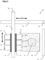
- FIG. 2 shows a top view of a 3D printing device 10.
- the 3D printing device 10 is essentially as with reference to FIG Figure 1 described.
- the 3D printing device 10 differs from the described device in that three discharge devices 14 are provided for pressure mass and three confocal measuring devices 20.
- the first two discharge devices 14 are as with reference to FIG Figure 1 described.
- the third discharge device 14 is designed as a further jetting nozzle 34 and is provided for setting support material.
- the confocal measuring devices 20 are each assigned to one of the discharge devices 14.
- the confocal measuring devices 20 and the discharge devices 14 are arranged opposite one another on the transport carriage 32, which moves the print head 12 along the Y axis.
- Figure 3 shows a side view of a height measurement according to an embodiment of the invention.
- a jetting nozzle 16 and the confocal measuring device 20 are shown above the base plate 24.
- the jetting nozzle 16 deposits droplets 36 which form the printed voxels when they strike the object 22 or the base plate 24.
- the jetting nozzle 16 is arranged behind the confocal measuring device 20, so that when printing, a height measurement is first carried out via the confocal measuring device 20, so that the positions at which printing masses to be printed can be printed can be determined without contact.
- the confocal measuring device 20 can also be used for the preliminary scan. However, the confocal measuring device 20 can also be used in such a way that the positions of printed printing masses are non-contact after printing can be determined, for example in order to obtain a CAD model of the printed object 22.
- a first printing error is a defect 38 which has already been measured by the confocal measuring device 20 and which can be corrected by the printing device 10 according to the invention while the current layer is being printed.
- the 3D printing device 10 determines that it is only a single or a few non-printed voxels, so that the defect 38 can be remedied immediately by a targeted reprint.
- the printed object 22 has another printing error in the form of an air pocket 40, i.e. a defect 38, which is already completely enclosed by pressure mass.
- the air inclusion 40 can be recognized by the confocal measuring device 20, since several interfaces of pressure mass and air occur in the measuring light beam, so that, provided the air inclusion 40 is still in the measuring range of the confocal measuring device 20, there are several dominant wavelengths in the received signal. If the air inclusion 40 is recognized, an error message can be generated, for example, or a message can be sent to the main control device, so that the printed object 22 can be imposed, for example, or further quality checks can be carried out. In the field of optics and medical technology in particular, such errors as the air trap 40 are often not permissible and their detection is therefore necessary. In the event of an error that cannot be corrected, the time to detect the error is reduced to a minimum.
- Another printing error is shown in the form of an elevation above the object 22 and shows a possible inclusion of foreign material 42 of a material, for example from the environment, e.g. B. dust particles, or which can consist of hardened, separated material from the jetting nozzle 16.
- the foreign material inclusion 42 can be confocal Measuring device 20 can be recognized because the distance to the object 22 changes briefly. With the presented 3D printing device, it can be determined whether the foreign material inclusion 42 is the same material as the object 22, namely printing mass or supporting mass, or a different material, since the reflection properties of the interface environment / foreign material inclusion 42 are different than at the interface environment / object 22.
- the foreign material inclusion 42 After detection of the foreign material inclusion 42, it can be provided, so far as can be determined that it is on the surface of the object 22, ie above the printed layers of the object 22, to generate corresponding warning messages the user can intervene, or provision can be made for the foreign material inclusion 42 to be removed automatically, for example with the aid of a robot arm.
- a foreign component 44 is also shown, which has been positioned, for example, using a rotor arm or manually on the printed object 22.
- the foreign component 44 is to be overprinted with one or more layers of printing compound, so that it is finally embedded in the object 22.
- the foreign component 44 is shown here as a cuboid, but it can also be a very flat foreign component 44, for example an electronic circuit board or a microchip.
- the position of the foreign component 44 is determined.
- the surface of the object 22 with the foreign component 44 positioned therein is measured in the scanning step by means of the confocal measuring device 20 and the position of a surface on which printing masses to be printed can be printed is determined.
- the determined data can, for example, be transferred to the control system in order to create a CAD model therefrom or to update the CAD model of the object 22.
- the distance between the jetting nozzle 16 and the last printed layer is shown as the discharge height h 1 .
- the distance between the confocal measuring device 20 and the last printed layer is shown as h.
- the geometry can be used to convert the two quantities into each other. Since the foreign component 44 on the printed object 22 in height by an amount measured by the confocal measuring device 20, can be provided when overprinting the foreign component 44, the distance of the jetting nozzle 16 to the base plate 24 by the corresponding amount, so that the discharge height h 1 above Object 22 remains constant during printing to keep the quality of printed object 22 constant.
- Figure 4 shows a side view of a height measurement according to a further embodiment of the invention. Shown is a dispenser 18 with a confocal measuring device 20 running on the base plate 24 while the object 22 is being printed.
- the dispenser 18 deposits strands 46 of printing material on the base plate 24, so that layers 48 are formed.
- the distance between the dispenser 18 and the last printed layer is again shown as the discharge height h 1 . If the discharge height h 1 is sufficient, the printed strand 46 ideally has a cylindrical strand cross section.
- the strand 46 is easily deformed by the movement of the dispenser 18. A further deformation of the strand 46 also results when the discharge height h 1 is too low.
- the deformation can be corrected by the continuous measurement or calculation of the discharge height h 1 by the confocal measuring device 20, e.g. B. by adjusting the discharge height h 1 .
- Figure 4 also shows an embodiment of the system 21 with the confocal measuring device 20.
- the system 21 refers to the confocal measuring device 20 and an evaluation unit 58, which are functionally connected to one another.
- the evaluation unit 58 is embodied integrated in a controller 23.
- the controller 23 comprises an external light source 50, a spectrometer 52 and the evaluation unit 58 in a common housing.
- the evaluation unit 58 and / or the light source 50 can be provided as suitable external units by means of suitable interfaces.
- the confocal measuring device 20 has a light source 50, which is, for example, a white light source with a homogeneous light spectrum, in particular a white light LED.
- the light from the light source 50 is guided by means of an optical waveguide 25 to a confocal lens arrangement 54, which was indicated in the drawing by way of example by four collimator lenses. Due to the confocal lens arrangement 54, the light emanating from the light source 50 experiences a chromatic aberration, so that blue light is refracted more than red light.
- a filter 56 is arranged behind the confocal lens arrangement 54, which filters out those spectral components of the light source 50 which lead to an unwanted hardening of the printed but not yet hardened layers 48.
- the light from the light source 50 is directed toward the last printed layer 48 or to that Figure 3 described flaws 38, air pockets 40 and surfaces of foreign components 44, it is reflected on them and runs via the same light path, namely via the filter 56, the confocal lens arrangement 54 and the optical waveguide 25 back to the controller 23, in the measurement of the reflected light he follows.
- the spectrometer 52 is connected to the evaluation unit 58.
- the evaluation unit 58 typically includes a CPU and storage means, as well as suitable interfaces to further computing units or to output devices such as printers, monitors, etc. In particular, it has a module for determining the dominant wavelengths in the spectrum detected by the spectrometer 52, and a database that provides an assignment of frequencies of the dominant wavelength, wavelength intensity and material.
- the spectrometer 52 and the evaluation unit 58 are thus set up to measure single- or multi-layer materials, so that the discharge height h 1 can be calculated and so that z. B. also related to Figure 3 defects 38 described, air pockets 40 and surfaces of foreign components 44 can be detected.
- the confocal measuring device 20 has in the focus area, ie. H. on the surface of the object 22, a light spot diameter in the range of 5 microns to 100 microns, preferably about 50 microns.
- the resolution of the system 21 when determining the distance between the print head 12 or the confocal measuring device 20 from the surface can be in the range from 10 nm to 0.5 ⁇ m, preferably between 20 nm and 50 nm.
- the confocal measuring device 20 is preferred in this way designed that it has at least in the X and Y direction between 100 and 200 microns accuracy, which corresponds approximately to the size of a voxel. The accuracy is also limited by the measurement tolerance in mechanics, i.e. H. due to the rigidity of the attachment of the confocal measuring device 20 and the discharge device 14 to the transport carriage 32.
- Figure 5 shows a jetting nozzle 16 in a side view above the base plate 24, the base plate 24 being shown at two different discharge heights h 1 relative to the jetting nozzle 16. Due to tolerance in the mechanics and in the nozzle geometry, the droplets that are applied, shown here as pressure jets 37, are not ejected vertically, but are within a certain tolerance range, which forms a cone 70.
- the cone 70 is shown with a cone opening ⁇ .
- the tip of the cone 70 forms an outlet opening 68 of the jetting nozzle 16.
- FIG Figure 5 By printing predetermined printing figures or printing patterns and by measuring the position or surface of the printing figures, a determination of the trajectory tolerance is shown in FIG Figure 5 with ⁇ X1 (h 1 ) and ⁇ X2 (h 1 ), depending on the discharge height h 1 . The values then obtained can be used to adjust a discharge angle ⁇ of the jetting nozzle 16 or provide guide values for a wear indicator of the jetting nozzle 16.
- Figure 6 shows the base plate 24 twice in a lateral sectional view, on which (purely by way of example three) test bodies 62 are arranged at a certain distance from one another.
- the base plate 24 can be compared with a standard position 74 be determined.
- the tilt and offset of the base plate 24 in the Y direction are also measured.
- the position of a printing plane 60 can be described by specifying the tilt and the offset. After determining the tilt and the offset, the position of the pressure plane 60 can be adjusted manually or automatically to take the standard position 74.
- Figure 7 shows a perspective view of the base plate 24 with a correcting device 72 acting thereon.
- the correcting device 72 is, for example, functionally connected to the system 21 with the confocal measuring device 20 via the main control device and is set up to correct the position of the pressure plane 60.
- the correction device 72 has offset actuators 64 and tilt actuators 66, by means of which the actuators with reference to Figure 6 described offset ⁇ X and ⁇ Y and ⁇ Z and the tilt ⁇ of the base plate 24 are adjustable.
Claims (8)
- Procédé de fabrication d'une pièce en élastomère de silicone (22) par utilisation d'un dispositif d'impression 3D (10) avec au moins une tête d'impression (12), qui présente au moins un dispositif de dépôt (14), qui est conçu pour placer des masses d'impression à des positions de consigne afin de produire des pièces en élastomère de silicone (22) par voie générative, dans lequel le dispositif d'impression 3D (10) présente un système (21) avec au moins un dispositif de mesure confocal (20), qui est conçu pour déterminer sans contact par mesure de distance chromatique confocale une distance de la tête d'impression (12) à une surface, sur laquelle des masses d'impression à imprimer peuvent être imprimées,
dans lequel le système (21) comprend une source de lumière (50), qui émet une lumière polychromatique et le dispositif de mesure confocal (20) comprend un agencement de lentille(s) (54) dans lequel une ou plusieurs lentille(s) est/sont disposée(s) de façon confocale, et qui est configuré de telle manière que la lumière de la source de lumière (50) soit décomposée en ses longueurs d'onde monochromatiques,
dans lequel on détermine sans contact au moyen du système (21) présentant au moins un dispositif de mesure confocal (20) pendant une opération d'impression par une mesure de distance chromatique confocale une distance de la tête d'impression à une surface, sur laquelle des masses d'impression à imprimer peuvent être imprimées, ou
dans lequel on détermine sans contact, dans une étape de balayage au moyen du système (21) présentant le dispositif de mesure confocal (20), avant l'opération d'impression par une mesure de distance chromatique confocale la position d'une surface, sur laquelle des masses d'impression à imprimer peuvent être imprimées. - Procédé selon la revendication 1, caractérisé en ce que l'on détecte et on corrige et/ou on rectifie et/ou on enregistre des défauts d'impression, en particulier des masses d'impression non imprimées et des dépôts de matière étrangère.
- Procédé selon une des revendications 1 ou 2, caractérisé en ce que l'on calibre le dispositif d'impression 3D (10) à l'aide de la distance déterminée sans contact de la tête d'impression (12) à la surface, sur laquelle des masses d'impression à imprimer peuvent être imprimées.
- Procédé selon l'une quelconque des revendications 1 à 3, caractérisé en ce l'on détermine sans contact à l'étape de balayage avant l'opération d'impression la position de la surface, sur laquelle les masses d'impression à imprimer peuvent être imprimées, et en ce que l'on établit un modèle CAD de la surface déterminée.
- Procédé selon l'une quelconque des revendications 1 à 4, caractérisé en ce l'on dispose au moins un composant étranger (44) sur une plaque de base (24) ou sur une couche imprimée (48), dans lequel on détermine la position de la surface imprimable du composant étranger (44) au moyen du système (21) avec le dispositif de mesure confocal (20).
- Procédé selon l'une quelconque des revendications 1 à 5, caractérisé en ce que l'on détermine sans contact après une opération d'impression au moyen du système (21) avec le dispositif de mesure confocal (20) aussi après une opération d'impression les positions de masses d'impression imprimées.
- Procédé selon l'une quelconque des revendications 1 à 6, caractérisé en ce que l'on détermine et on produit, à l'aide des données du système (21) présentant le dispositif de mesure confocal (20), des indicateurs déterminant la qualité de la pièce imprimée en élastomère de silicone (22), en particulier la rugosité de surface, la texture de surface, la position et les tolérances de planéité.
- Procédé selon l'une quelconque des revendications 1 à 7, caractérisé en ce que l'on imprime sur des couches, qui sont formées au moins en partie de masse d'impression transparente.
Applications Claiming Priority (1)
| Application Number | Priority Date | Filing Date | Title |
|---|---|---|---|
| PCT/EP2016/067286 WO2018014948A1 (fr) | 2016-07-20 | 2016-07-20 | Dispositif d'impression 3d et procédé pour produire des objets |
Publications (2)
| Publication Number | Publication Date |
|---|---|
| EP3487687A1 EP3487687A1 (fr) | 2019-05-29 |
| EP3487687B1 true EP3487687B1 (fr) | 2019-12-25 |
Family
ID=56464215
Family Applications (1)
| Application Number | Title | Priority Date | Filing Date |
|---|---|---|---|
| EP16741028.1A Active EP3487687B1 (fr) | 2016-07-20 | 2016-07-20 | Procédé d'impression 3d pour produire des objets |
Country Status (6)
| Country | Link |
|---|---|
| US (1) | US20190217545A1 (fr) |
| EP (1) | EP3487687B1 (fr) |
| JP (1) | JP6801078B2 (fr) |
| KR (1) | KR102207691B1 (fr) |
| CN (1) | CN109476079B (fr) |
| WO (1) | WO2018014948A1 (fr) |
Families Citing this family (16)
| Publication number | Priority date | Publication date | Assignee | Title |
|---|---|---|---|---|
| US10291816B2 (en) * | 2015-01-23 | 2019-05-14 | Xerox Corporation | System and method for identification and control of z-axis printhead position in a three-dimensional object printer |
| KR102365745B1 (ko) * | 2017-06-01 | 2022-02-22 | 한국전자통신연구원 | 3d 객체의 출력 위치 보정 장치 및 방법 |
| CN111801050B (zh) * | 2018-03-08 | 2024-03-08 | 美国西门子医疗系统股份有限公司 | 使用增添方法的准直器的三维打印的系统和方法 |
| FR3079443B1 (fr) * | 2018-03-29 | 2021-05-14 | Association Pour Les Transferts De Tech Du Mans | Procede de fabrication additive d'une piece en elastomere, installation de fabrication et piece associees |
| DE102018109408A1 (de) * | 2018-04-19 | 2019-10-24 | Siteco Beleuchtungstechnik Gmbh | Led-modul mit silikonlinse in 3d druck |
| JP2020114630A (ja) * | 2019-01-17 | 2020-07-30 | 株式会社リコー | 造形装置、システム、方法およびプログラム |
| CN110186391A (zh) * | 2019-05-22 | 2019-08-30 | 浙江大学 | 一种三维模型梯度扫描方法 |
| CN112008976B (zh) * | 2019-05-31 | 2023-01-31 | 西门子股份公司 | 增材制造装置及方法 |
| KR20200144198A (ko) * | 2019-06-17 | 2020-12-29 | 삼성디스플레이 주식회사 | 잉크 액적 부피 측정장치와, 그것을 이용한 잉크 액적 부피 측정방법과, 그 잉크 액적 부피 측정장치를 활용하는 박막층 형성장치 및, 상기 박막층 형성장치를 이용한 디스플레이 장치의 제조방법 |
| US20210154950A1 (en) * | 2019-11-21 | 2021-05-27 | Divergent Technologies, Inc. | Fixtureless robotic assembly |
| KR20220121251A (ko) * | 2019-12-31 | 2022-08-31 | 엘켐 실리콘즈 상하이 컴퍼니 리미티드 | 적층 제조용 가용성 지지체 재료 |
| IT202000010423A1 (it) * | 2020-05-08 | 2021-11-08 | Graf Synergy Srl | Procedimento per la stampa tridimensionale di manufatti cavi |
| JPWO2022054144A1 (fr) * | 2020-09-08 | 2022-03-17 | ||
| WO2022063393A1 (fr) | 2020-09-22 | 2022-03-31 | Wacker Chemie Ag | Méthode et méthode d'impression 3d pour la fabrication couche par couche d'objets à l'aide d'une impression par transfert à laser |
| CN112622273A (zh) * | 2021-01-15 | 2021-04-09 | 东莞市精诚世中智能装备有限公司 | 一种基于压电陶瓷的全彩树脂比例喷射阀 |
| FR3126332A1 (fr) * | 2021-08-27 | 2023-03-03 | Saint-Gobain Weber France | Contrôle d’impression 3D |
Family Cites Families (31)
| Publication number | Priority date | Publication date | Assignee | Title |
|---|---|---|---|---|
| US4530879A (en) | 1983-03-04 | 1985-07-23 | Minnesota Mining And Manufacturing Company | Radiation activated addition reaction |
| US4510094A (en) | 1983-12-06 | 1985-04-09 | Minnesota Mining And Manufacturing Company | Platinum complex |
| US4916169A (en) | 1988-09-09 | 1990-04-10 | Minnesota Mining And Manufacturing Company | Visible radiation activated hydrosilation reaction |
| CA2014996A1 (fr) | 1989-05-19 | 1990-11-19 | Joel D. Oxman | Reaction d'hydrosilation activee par les rayonnements |
| US6046250A (en) | 1990-12-13 | 2000-04-04 | 3M Innovative Properties Company | Hydrosilation reaction utilizing a free radical photoinitiator |
| US6376569B1 (en) | 1990-12-13 | 2002-04-23 | 3M Innovative Properties Company | Hydrosilation reaction utilizing a (cyclopentadiene)(sigma-aliphatic) platinum complex and a free radical photoinitiator |
| JPH07120401A (ja) * | 1993-09-03 | 1995-05-12 | Olympus Optical Co Ltd | 透明物体内の気泡検出装置 |
| US6150546A (en) | 1999-05-03 | 2000-11-21 | General Electric Company | Irradiation-curable silicone compositions, photo-active platinum (IV) compounds, and method |
| US6127446A (en) | 1999-05-03 | 2000-10-03 | General Electric Company | Irradiation-curable silicone compositions, photo-active platinum (IV) compounds, and method |
| US7625198B2 (en) * | 2004-08-11 | 2009-12-01 | Cornell Research Foundation, Inc. | Modular fabrication systems and methods |
| JP2007106070A (ja) * | 2005-10-17 | 2007-04-26 | Kokusai Kiban Zairyo Kenkyusho:Kk | 3次元積層造形方法とその装置 |
| US20090062417A1 (en) | 2007-08-31 | 2009-03-05 | Momentive Performance Materials Gmbh | Process For The Continuous Manufacturing Of Shaped Articles And Use Of Silicone Rubber Compositions In That Process |
| DE102008000156A1 (de) * | 2008-01-25 | 2009-07-30 | Wacker Chemie Ag | Durch Bestrahlung aktivierte Hydrosilylierungsreaktionen |
| DE102008043316A1 (de) | 2008-10-30 | 2010-05-06 | Wacker Chemie Ag | Verfahren zur Herstellung von Siliconformkörpern aus durch Licht vernetzbaren Siliconmischungen |
| DE102009002231A1 (de) * | 2009-04-06 | 2010-10-07 | Wacker Chemie Ag | Bei Raumtemperatur selbsthaftende Pt-katalysierte additions-vernetzende Siliconzusammensetzungen |
| DE102009027486A1 (de) | 2009-07-06 | 2011-01-13 | Wacker Chemie Ag | Verfahren zur Herstellung von Siliconbeschichtungen und Siliconformkörpern aus durch Licht vernetzbaren Siliconmischungen |
| CN201780274U (zh) * | 2010-09-03 | 2011-03-30 | 西安工业大学 | 一种光学表面亚表层损伤测量装置 |
| DE102010043149A1 (de) | 2010-10-29 | 2012-05-03 | Wacker Chemie Ag | Hochtransparente durch Licht vernetzbare Siliconmischungen |
| DE102011106614A1 (de) | 2011-06-16 | 2014-03-06 | Arburg Gmbh + Co Kg | Vorrichtung und Verfahren zur Herstellung eines dreidimensionalen Gegenstandes |
| DE102011108799A1 (de) | 2011-07-29 | 2013-01-31 | Vermes Microdispensing GmbH | Dosiersystem und Dosierverfahren |
| DE102012000664B4 (de) | 2012-01-17 | 2014-07-10 | Mirjana Jovanovic | Vorrichtung zur Erzeugung von dreidimmensionalen Objekten |
| JP5975562B2 (ja) * | 2012-03-02 | 2016-08-23 | オリンパス株式会社 | 撮像装置及び撮像装置の作動方法 |
| WO2014052811A1 (fr) * | 2012-09-28 | 2014-04-03 | Rudolph Technologies, Inc. | Inspection de substrats par étalonnage et imagerie |
| WO2015017579A1 (fr) * | 2013-07-31 | 2015-02-05 | Organovo, Inc. | Dispositifs, systèmes et procédés automatisés pour la fabrication de tissus |
| US9233507B2 (en) * | 2013-11-22 | 2016-01-12 | Charles Bibas | 3D printing apparatus with sensor device |
| US9764515B2 (en) * | 2014-05-01 | 2017-09-19 | Musc Foundation For Research Development | Multidispensor cartesian robotic printer |
| US10252466B2 (en) * | 2014-07-28 | 2019-04-09 | Massachusetts Institute Of Technology | Systems and methods of machine vision assisted additive fabrication |
| US20160098824A1 (en) * | 2014-10-03 | 2016-04-07 | Tyco Electronics Corporation | Three dimensional printing inspection apparatus and method |
| CN104290330B (zh) * | 2014-10-31 | 2017-07-04 | 珠海天威飞马打印耗材有限公司 | 一种3d打印机及打印方法 |
| DE102014222685A1 (de) * | 2014-11-06 | 2016-05-12 | Wacker Chemie Ag | Verfahren zur Herstellung von Siliconelastomerteilen |
| DE202015103932U1 (de) | 2015-07-28 | 2015-09-24 | BigRep GmbH | Ausgleich der Unebenheit einer Grundplatte beim 3D-Druck |
-
2016
- 2016-07-20 EP EP16741028.1A patent/EP3487687B1/fr active Active
- 2016-07-20 JP JP2019502777A patent/JP6801078B2/ja active Active
- 2016-07-20 CN CN201680087760.8A patent/CN109476079B/zh not_active Expired - Fee Related
- 2016-07-20 KR KR1020197001802A patent/KR102207691B1/ko active IP Right Grant
- 2016-07-20 WO PCT/EP2016/067286 patent/WO2018014948A1/fr active Search and Examination
- 2016-07-20 US US16/319,420 patent/US20190217545A1/en not_active Abandoned
Non-Patent Citations (1)
| Title |
|---|
| None * |
Also Published As
| Publication number | Publication date |
|---|---|
| CN109476079A (zh) | 2019-03-15 |
| JP6801078B2 (ja) | 2020-12-16 |
| CN109476079B (zh) | 2021-04-06 |
| US20190217545A1 (en) | 2019-07-18 |
| JP2019525856A (ja) | 2019-09-12 |
| EP3487687A1 (fr) | 2019-05-29 |
| KR20190018723A (ko) | 2019-02-25 |
| WO2018014948A1 (fr) | 2018-01-25 |
| KR102207691B1 (ko) | 2021-01-26 |
Similar Documents
| Publication | Publication Date | Title |
|---|---|---|
| EP3487687B1 (fr) | Procédé d'impression 3d pour produire des objets | |
| EP3359372B1 (fr) | Dispositif d'impression 3d et procédé de fabrication d'un objet à l'aide d'un dispositif d'impression 3d | |
| EP3362260B1 (fr) | Procédé de fabrication de pièces en élastomères de silicone présentant une qualité d'impression améliorée | |
| EP3225383B1 (fr) | Dispositif et procédé de production de structures tridimensionnelles | |
| EP3041661B1 (fr) | Despositif d'aligner des composants d'une machine rotatif | |
| EP3362262A1 (fr) | Procédé et dispositif de fabrication d'un objet tridimensionnel | |
| DE102012202487A1 (de) | Verfahren zum Aufschmelzen/Sintern von Pulverpartikeln zur schichtweisen Herstellung von dreidimensionalen Objekten | |
| WO2021073717A1 (fr) | Dispositif d'impression 3d et procédé de production d'objets avec une qualité d'impression accrue | |
| EP2832546A1 (fr) | Imprimante dotée d'une commande de tête d'impression | |
| DE102016200465A1 (de) | System und verfahren zum erzeugen von testmustern zum messen einer trennung zwischen druckkopf und substrat in einem drucker | |
| DE102017210994A1 (de) | Messsystem für eine Vorrichtung zum generativen Herstellen eines dreidimensionalen Objekts | |
| DE102017217682A1 (de) | Verfahren zur schichtweisen additiven Herstellung dreidimensional ausgebildeter Bauteile | |
| EP3956128B1 (fr) | Procédé de fabrication d'au moins une couche solide conformément à des données géométriques spécifiées | |
| EP3956126B1 (fr) | Procédé de fabrication d'au moins une couche solide sur un support pouvant tourner autour d'un axe de rotation | |
| DE102015115231B4 (de) | Verfahren und Vorrichtung zur Herstellung 3-dimensionaler Modelle mit einem strahlungshärtendem Kunststoff | |
| CH715621A1 (de) | Verfahren und Vorrichtung zur Herstellung eines dreidimensionalen Objekts. | |
| DE102022111789B3 (de) | Verfahren und Vorrichtung zum Erzeugen einer dreidimensionalen Struktur in einem Lithographiefluid | |
| KR102238509B1 (ko) | 3d 프린팅 패턴의 치수정밀도 평가방법 | |
| DE112020002131T5 (de) | Herstellungsverfahren und -gerät eines planaren Schichtmaterials |
Legal Events
| Date | Code | Title | Description |
|---|---|---|---|
| STAA | Information on the status of an ep patent application or granted ep patent |
Free format text: STATUS: THE INTERNATIONAL PUBLICATION HAS BEEN MADE |
|
| PUAI | Public reference made under article 153(3) epc to a published international application that has entered the european phase |
Free format text: ORIGINAL CODE: 0009012 |
|
| STAA | Information on the status of an ep patent application or granted ep patent |
Free format text: STATUS: REQUEST FOR EXAMINATION WAS MADE |
|
| REG | Reference to a national code |
Ref country code: DE Ref legal event code: R079 Ref document number: 502016008150 Country of ref document: DE Free format text: PREVIOUS MAIN CLASS: B29C0067000000 Ipc: B29C0064386000 |
|
| 17P | Request for examination filed |
Effective date: 20190110 |
|
| AK | Designated contracting states |
Kind code of ref document: A1 Designated state(s): AL AT BE BG CH CY CZ DE DK EE ES FI FR GB GR HR HU IE IS IT LI LT LU LV MC MK MT NL NO PL PT RO RS SE SI SK SM TR |
|
| AX | Request for extension of the european patent |
Extension state: BA ME |
|
| RIC1 | Information provided on ipc code assigned before grant |
Ipc: B29C 64/135 20170101ALI20190507BHEP Ipc: B29C 64/112 20170101ALI20190507BHEP Ipc: B29C 64/386 20170101AFI20190507BHEP Ipc: B29C 64/264 20170101ALI20190507BHEP |
|
| GRAP | Despatch of communication of intention to grant a patent |
Free format text: ORIGINAL CODE: EPIDOSNIGR1 |
|
| STAA | Information on the status of an ep patent application or granted ep patent |
Free format text: STATUS: GRANT OF PATENT IS INTENDED |
|
| DAX | Request for extension of the european patent (deleted) | ||
| INTG | Intention to grant announced |
Effective date: 20190809 |
|
| RIN1 | Information on inventor provided before grant (corrected) |
Inventor name: PETER, MAXIMILIAN Inventor name: ELLER, KLAUS |
|
| DAV | Request for validation of the european patent (deleted) | ||
| GRAS | Grant fee paid |
Free format text: ORIGINAL CODE: EPIDOSNIGR3 |
|
| GRAA | (expected) grant |
Free format text: ORIGINAL CODE: 0009210 |
|
| STAA | Information on the status of an ep patent application or granted ep patent |
Free format text: STATUS: THE PATENT HAS BEEN GRANTED |
|
| AK | Designated contracting states |
Kind code of ref document: B1 Designated state(s): AL AT BE BG CH CY CZ DE DK EE ES FI FR GB GR HR HU IE IS IT LI LT LU LV MC MK MT NL NO PL PT RO RS SE SI SK SM TR |
|
| REG | Reference to a national code |
Ref country code: GB Ref legal event code: FG4D Free format text: NOT ENGLISH |
|
| REG | Reference to a national code |
Ref country code: CH Ref legal event code: EP |
|
| REG | Reference to a national code |
Ref country code: AT Ref legal event code: REF Ref document number: 1216691 Country of ref document: AT Kind code of ref document: T Effective date: 20200115 |
|
| REG | Reference to a national code |
Ref country code: DE Ref legal event code: R096 Ref document number: 502016008150 Country of ref document: DE |
|
| REG | Reference to a national code |
Ref country code: IE Ref legal event code: FG4D Free format text: LANGUAGE OF EP DOCUMENT: GERMAN |
|
| REG | Reference to a national code |
Ref country code: NL Ref legal event code: FP |
|
| PG25 | Lapsed in a contracting state [announced via postgrant information from national office to epo] |
Ref country code: BG Free format text: LAPSE BECAUSE OF FAILURE TO SUBMIT A TRANSLATION OF THE DESCRIPTION OR TO PAY THE FEE WITHIN THE PRESCRIBED TIME-LIMIT Effective date: 20200325 Ref country code: FI Free format text: LAPSE BECAUSE OF FAILURE TO SUBMIT A TRANSLATION OF THE DESCRIPTION OR TO PAY THE FEE WITHIN THE PRESCRIBED TIME-LIMIT Effective date: 20191225 Ref country code: LT Free format text: LAPSE BECAUSE OF FAILURE TO SUBMIT A TRANSLATION OF THE DESCRIPTION OR TO PAY THE FEE WITHIN THE PRESCRIBED TIME-LIMIT Effective date: 20191225 Ref country code: GR Free format text: LAPSE BECAUSE OF FAILURE TO SUBMIT A TRANSLATION OF THE DESCRIPTION OR TO PAY THE FEE WITHIN THE PRESCRIBED TIME-LIMIT Effective date: 20200326 Ref country code: NO Free format text: LAPSE BECAUSE OF FAILURE TO SUBMIT A TRANSLATION OF THE DESCRIPTION OR TO PAY THE FEE WITHIN THE PRESCRIBED TIME-LIMIT Effective date: 20200325 Ref country code: SE Free format text: LAPSE BECAUSE OF FAILURE TO SUBMIT A TRANSLATION OF THE DESCRIPTION OR TO PAY THE FEE WITHIN THE PRESCRIBED TIME-LIMIT Effective date: 20191225 Ref country code: LV Free format text: LAPSE BECAUSE OF FAILURE TO SUBMIT A TRANSLATION OF THE DESCRIPTION OR TO PAY THE FEE WITHIN THE PRESCRIBED TIME-LIMIT Effective date: 20191225 |
|
| REG | Reference to a national code |
Ref country code: LT Ref legal event code: MG4D |
|
| PG25 | Lapsed in a contracting state [announced via postgrant information from national office to epo] |
Ref country code: RS Free format text: LAPSE BECAUSE OF FAILURE TO SUBMIT A TRANSLATION OF THE DESCRIPTION OR TO PAY THE FEE WITHIN THE PRESCRIBED TIME-LIMIT Effective date: 20191225 Ref country code: HR Free format text: LAPSE BECAUSE OF FAILURE TO SUBMIT A TRANSLATION OF THE DESCRIPTION OR TO PAY THE FEE WITHIN THE PRESCRIBED TIME-LIMIT Effective date: 20191225 |
|
| PG25 | Lapsed in a contracting state [announced via postgrant information from national office to epo] |
Ref country code: AL Free format text: LAPSE BECAUSE OF FAILURE TO SUBMIT A TRANSLATION OF THE DESCRIPTION OR TO PAY THE FEE WITHIN THE PRESCRIBED TIME-LIMIT Effective date: 20191225 |
|
| PG25 | Lapsed in a contracting state [announced via postgrant information from national office to epo] |
Ref country code: EE Free format text: LAPSE BECAUSE OF FAILURE TO SUBMIT A TRANSLATION OF THE DESCRIPTION OR TO PAY THE FEE WITHIN THE PRESCRIBED TIME-LIMIT Effective date: 20191225 Ref country code: PT Free format text: LAPSE BECAUSE OF FAILURE TO SUBMIT A TRANSLATION OF THE DESCRIPTION OR TO PAY THE FEE WITHIN THE PRESCRIBED TIME-LIMIT Effective date: 20200520 Ref country code: RO Free format text: LAPSE BECAUSE OF FAILURE TO SUBMIT A TRANSLATION OF THE DESCRIPTION OR TO PAY THE FEE WITHIN THE PRESCRIBED TIME-LIMIT Effective date: 20191225 Ref country code: CZ Free format text: LAPSE BECAUSE OF FAILURE TO SUBMIT A TRANSLATION OF THE DESCRIPTION OR TO PAY THE FEE WITHIN THE PRESCRIBED TIME-LIMIT Effective date: 20191225 |
|
| PG25 | Lapsed in a contracting state [announced via postgrant information from national office to epo] |
Ref country code: SM Free format text: LAPSE BECAUSE OF FAILURE TO SUBMIT A TRANSLATION OF THE DESCRIPTION OR TO PAY THE FEE WITHIN THE PRESCRIBED TIME-LIMIT Effective date: 20191225 Ref country code: SK Free format text: LAPSE BECAUSE OF FAILURE TO SUBMIT A TRANSLATION OF THE DESCRIPTION OR TO PAY THE FEE WITHIN THE PRESCRIBED TIME-LIMIT Effective date: 20191225 Ref country code: IS Free format text: LAPSE BECAUSE OF FAILURE TO SUBMIT A TRANSLATION OF THE DESCRIPTION OR TO PAY THE FEE WITHIN THE PRESCRIBED TIME-LIMIT Effective date: 20200425 |
|
| REG | Reference to a national code |
Ref country code: DE Ref legal event code: R097 Ref document number: 502016008150 Country of ref document: DE |
|
| PG25 | Lapsed in a contracting state [announced via postgrant information from national office to epo] |
Ref country code: DK Free format text: LAPSE BECAUSE OF FAILURE TO SUBMIT A TRANSLATION OF THE DESCRIPTION OR TO PAY THE FEE WITHIN THE PRESCRIBED TIME-LIMIT Effective date: 20191225 Ref country code: ES Free format text: LAPSE BECAUSE OF FAILURE TO SUBMIT A TRANSLATION OF THE DESCRIPTION OR TO PAY THE FEE WITHIN THE PRESCRIBED TIME-LIMIT Effective date: 20191225 |
|
| PLBE | No opposition filed within time limit |
Free format text: ORIGINAL CODE: 0009261 |
|
| STAA | Information on the status of an ep patent application or granted ep patent |
Free format text: STATUS: NO OPPOSITION FILED WITHIN TIME LIMIT |
|
| 26N | No opposition filed |
Effective date: 20200928 |
|
| PG25 | Lapsed in a contracting state [announced via postgrant information from national office to epo] |
Ref country code: IT Free format text: LAPSE BECAUSE OF FAILURE TO SUBMIT A TRANSLATION OF THE DESCRIPTION OR TO PAY THE FEE WITHIN THE PRESCRIBED TIME-LIMIT Effective date: 20191225 |
|
| PG25 | Lapsed in a contracting state [announced via postgrant information from national office to epo] |
Ref country code: MC Free format text: LAPSE BECAUSE OF FAILURE TO SUBMIT A TRANSLATION OF THE DESCRIPTION OR TO PAY THE FEE WITHIN THE PRESCRIBED TIME-LIMIT Effective date: 20191225 Ref country code: PL Free format text: LAPSE BECAUSE OF FAILURE TO SUBMIT A TRANSLATION OF THE DESCRIPTION OR TO PAY THE FEE WITHIN THE PRESCRIBED TIME-LIMIT Effective date: 20191225 |
|
| PG25 | Lapsed in a contracting state [announced via postgrant information from national office to epo] |
Ref country code: LU Free format text: LAPSE BECAUSE OF NON-PAYMENT OF DUE FEES Effective date: 20200720 |
|
| PG25 | Lapsed in a contracting state [announced via postgrant information from national office to epo] |
Ref country code: IE Free format text: LAPSE BECAUSE OF NON-PAYMENT OF DUE FEES Effective date: 20200720 |
|
| PGFP | Annual fee paid to national office [announced via postgrant information from national office to epo] |
Ref country code: NL Payment date: 20210721 Year of fee payment: 6 |
|
| PGFP | Annual fee paid to national office [announced via postgrant information from national office to epo] |
Ref country code: FR Payment date: 20210729 Year of fee payment: 6 |
|
| PGFP | Annual fee paid to national office [announced via postgrant information from national office to epo] |
Ref country code: CH Payment date: 20210721 Year of fee payment: 6 Ref country code: BE Payment date: 20210721 Year of fee payment: 6 Ref country code: GB Payment date: 20210722 Year of fee payment: 6 Ref country code: DE Payment date: 20210721 Year of fee payment: 6 |
|
| PG25 | Lapsed in a contracting state [announced via postgrant information from national office to epo] |
Ref country code: TR Free format text: LAPSE BECAUSE OF FAILURE TO SUBMIT A TRANSLATION OF THE DESCRIPTION OR TO PAY THE FEE WITHIN THE PRESCRIBED TIME-LIMIT Effective date: 20191225 Ref country code: MT Free format text: LAPSE BECAUSE OF FAILURE TO SUBMIT A TRANSLATION OF THE DESCRIPTION OR TO PAY THE FEE WITHIN THE PRESCRIBED TIME-LIMIT Effective date: 20191225 Ref country code: CY Free format text: LAPSE BECAUSE OF FAILURE TO SUBMIT A TRANSLATION OF THE DESCRIPTION OR TO PAY THE FEE WITHIN THE PRESCRIBED TIME-LIMIT Effective date: 20191225 |
|
| PG25 | Lapsed in a contracting state [announced via postgrant information from national office to epo] |
Ref country code: MK Free format text: LAPSE BECAUSE OF FAILURE TO SUBMIT A TRANSLATION OF THE DESCRIPTION OR TO PAY THE FEE WITHIN THE PRESCRIBED TIME-LIMIT Effective date: 20191225 |
|
| REG | Reference to a national code |
Ref country code: AT Ref legal event code: MM01 Ref document number: 1216691 Country of ref document: AT Kind code of ref document: T Effective date: 20210720 |
|
| PG25 | Lapsed in a contracting state [announced via postgrant information from national office to epo] |
Ref country code: AT Free format text: LAPSE BECAUSE OF NON-PAYMENT OF DUE FEES Effective date: 20210720 |
|
| REG | Reference to a national code |
Ref country code: DE Ref legal event code: R119 Ref document number: 502016008150 Country of ref document: DE |
|
| REG | Reference to a national code |
Ref country code: CH Ref legal event code: PL |
|
| REG | Reference to a national code |
Ref country code: NL Ref legal event code: MM Effective date: 20220801 |
|
| GBPC | Gb: european patent ceased through non-payment of renewal fee |
Effective date: 20220720 |
|
| REG | Reference to a national code |
Ref country code: BE Ref legal event code: MM Effective date: 20220731 |
|
| PG25 | Lapsed in a contracting state [announced via postgrant information from national office to epo] |
Ref country code: LI Free format text: LAPSE BECAUSE OF NON-PAYMENT OF DUE FEES Effective date: 20220731 Ref country code: FR Free format text: LAPSE BECAUSE OF NON-PAYMENT OF DUE FEES Effective date: 20220731 Ref country code: CH Free format text: LAPSE BECAUSE OF NON-PAYMENT OF DUE FEES Effective date: 20220731 |
|
| PG25 | Lapsed in a contracting state [announced via postgrant information from national office to epo] |
Ref country code: GB Free format text: LAPSE BECAUSE OF NON-PAYMENT OF DUE FEES Effective date: 20220720 Ref country code: DE Free format text: LAPSE BECAUSE OF NON-PAYMENT OF DUE FEES Effective date: 20230201 Ref country code: BE Free format text: LAPSE BECAUSE OF NON-PAYMENT OF DUE FEES Effective date: 20220731 |
|
| PG25 | Lapsed in a contracting state [announced via postgrant information from national office to epo] |
Ref country code: NL Free format text: LAPSE BECAUSE OF NON-PAYMENT OF DUE FEES Effective date: 20220801 |
|
| PG25 | Lapsed in a contracting state [announced via postgrant information from national office to epo] |
Ref country code: SI Free format text: LAPSE BECAUSE OF FAILURE TO SUBMIT A TRANSLATION OF THE DESCRIPTION OR TO PAY THE FEE WITHIN THE PRESCRIBED TIME-LIMIT Effective date: 20191225 |