EP3487673B1 - Structure of reinforced cementitious material and process of making the same structure by a three-dimensional printing process - Google Patents
Structure of reinforced cementitious material and process of making the same structure by a three-dimensional printing process Download PDFInfo
- Publication number
- EP3487673B1 EP3487673B1 EP17751849.5A EP17751849A EP3487673B1 EP 3487673 B1 EP3487673 B1 EP 3487673B1 EP 17751849 A EP17751849 A EP 17751849A EP 3487673 B1 EP3487673 B1 EP 3487673B1
- Authority
- EP
- European Patent Office
- Prior art keywords
- module
- cavity
- hooking portion
- modules
- connecting element
- Prior art date
- Legal status (The legal status is an assumption and is not a legal conclusion. Google has not performed a legal analysis and makes no representation as to the accuracy of the status listed.)
- Active
Links
Images




Classifications
-
- B—PERFORMING OPERATIONS; TRANSPORTING
- B28—WORKING CEMENT, CLAY, OR STONE
- B28B—SHAPING CLAY OR OTHER CERAMIC COMPOSITIONS; SHAPING SLAG; SHAPING MIXTURES CONTAINING CEMENTITIOUS MATERIAL, e.g. PLASTER
- B28B1/00—Producing shaped prefabricated articles from the material
- B28B1/001—Rapid manufacturing of 3D objects by additive depositing, agglomerating or laminating of material
-
- B—PERFORMING OPERATIONS; TRANSPORTING
- B28—WORKING CEMENT, CLAY, OR STONE
- B28B—SHAPING CLAY OR OTHER CERAMIC COMPOSITIONS; SHAPING SLAG; SHAPING MIXTURES CONTAINING CEMENTITIOUS MATERIAL, e.g. PLASTER
- B28B23/00—Arrangements specially adapted for the production of shaped articles with elements wholly or partly embedded in the moulding material; Production of reinforced objects
- B28B23/02—Arrangements specially adapted for the production of shaped articles with elements wholly or partly embedded in the moulding material; Production of reinforced objects wherein the elements are reinforcing members
- B28B23/22—Arrangements specially adapted for the production of shaped articles with elements wholly or partly embedded in the moulding material; Production of reinforced objects wherein the elements are reinforcing members assembled from preformed parts
-
- E—FIXED CONSTRUCTIONS
- E04—BUILDING
- E04B—GENERAL BUILDING CONSTRUCTIONS; WALLS, e.g. PARTITIONS; ROOFS; FLOORS; CEILINGS; INSULATION OR OTHER PROTECTION OF BUILDINGS
- E04B2/00—Walls, e.g. partitions, for buildings; Wall construction with regard to insulation; Connections specially adapted to walls
- E04B2/02—Walls, e.g. partitions, for buildings; Wall construction with regard to insulation; Connections specially adapted to walls built-up from layers of building elements
- E04B2/14—Walls having cavities in, but not between, the elements, i.e. each cavity being enclosed by at least four sides forming part of one single element
- E04B2/16—Walls having cavities in, but not between, the elements, i.e. each cavity being enclosed by at least four sides forming part of one single element using elements having specially-designed means for stabilising the position
- E04B2/18—Walls having cavities in, but not between, the elements, i.e. each cavity being enclosed by at least four sides forming part of one single element using elements having specially-designed means for stabilising the position by interlocking of projections or inserts with indentations, e.g. of tongues, grooves, dovetails
-
- E—FIXED CONSTRUCTIONS
- E04—BUILDING
- E04B—GENERAL BUILDING CONSTRUCTIONS; WALLS, e.g. PARTITIONS; ROOFS; FLOORS; CEILINGS; INSULATION OR OTHER PROTECTION OF BUILDINGS
- E04B2/00—Walls, e.g. partitions, for buildings; Wall construction with regard to insulation; Connections specially adapted to walls
- E04B2/02—Walls, e.g. partitions, for buildings; Wall construction with regard to insulation; Connections specially adapted to walls built-up from layers of building elements
- E04B2002/0202—Details of connections
- E04B2002/0243—Separate connectors or inserts, e.g. pegs, pins or keys
- E04B2002/0254—Tie rods
-
- E—FIXED CONSTRUCTIONS
- E04—BUILDING
- E04B—GENERAL BUILDING CONSTRUCTIONS; WALLS, e.g. PARTITIONS; ROOFS; FLOORS; CEILINGS; INSULATION OR OTHER PROTECTION OF BUILDINGS
- E04B5/00—Floors; Floor construction with regard to insulation; Connections specially adapted therefor
- E04B5/02—Load-carrying floor structures formed substantially of prefabricated units
- E04B5/08—Load-carrying floor structures formed substantially of prefabricated units assembled of block-shaped elements, e.g. hollow stones
-
- E—FIXED CONSTRUCTIONS
- E04—BUILDING
- E04C—STRUCTURAL ELEMENTS; BUILDING MATERIALS
- E04C2/00—Building elements of relatively thin form for the construction of parts of buildings, e.g. sheet materials, slabs, or panels
- E04C2/02—Building elements of relatively thin form for the construction of parts of buildings, e.g. sheet materials, slabs, or panels characterised by specified materials
- E04C2/04—Building elements of relatively thin form for the construction of parts of buildings, e.g. sheet materials, slabs, or panels characterised by specified materials of concrete or other stone-like material; of asbestos cement; of cement and other mineral fibres
- E04C2/041—Building elements of relatively thin form for the construction of parts of buildings, e.g. sheet materials, slabs, or panels characterised by specified materials of concrete or other stone-like material; of asbestos cement; of cement and other mineral fibres composed of a number of smaller elements, e.g. bricks, also combined with a slab of hardenable material
-
- E—FIXED CONSTRUCTIONS
- E04—BUILDING
- E04C—STRUCTURAL ELEMENTS; BUILDING MATERIALS
- E04C3/00—Structural elongated elements designed for load-supporting
- E04C3/02—Joists; Girders, trusses, or trusslike structures, e.g. prefabricated; Lintels; Transoms; Braces
- E04C2003/026—Braces
-
- E—FIXED CONSTRUCTIONS
- E04—BUILDING
- E04C—STRUCTURAL ELEMENTS; BUILDING MATERIALS
- E04C3/00—Structural elongated elements designed for load-supporting
- E04C3/02—Joists; Girders, trusses, or trusslike structures, e.g. prefabricated; Lintels; Transoms; Braces
- E04C3/20—Joists; Girders, trusses, or trusslike structures, e.g. prefabricated; Lintels; Transoms; Braces of concrete or other stone-like material, e.g. with reinforcements or tensioning members
- E04C3/22—Joists; Girders, trusses, or trusslike structures, e.g. prefabricated; Lintels; Transoms; Braces of concrete or other stone-like material, e.g. with reinforcements or tensioning members built-up by elements jointed in line
Definitions
- the object of the present invention is a structure of reinforced cementitious material and a process of making the same by a three-dimensional printing process.
- the invention can be advantageously applied in the architectural, design and building fields, for example for erecting buildings and also in the construction engineering field.
- the subtractive technology provides to take away a cementitious material from a rough preform in order to obtain a finished product.
- the formative technology provides to pour a cementitious material at the liquid (green) state inside adapted moulds (casings) wherein the material solidifies for defining the finished product: at the end of the solidifying step, the finished product is then extracted from the mould.
- the object of the present invention consists of substantially solving at least one of the inconveniencies and/or limitations of the previous solutions.
- DE102014206697 discloses a process of making a structure by a three-dimensional printing process of for example cementitious material.
- a first object of the present invention consists of providing a structure of reinforced cementitious material exhibiting excellent mechanical properties and, at the same time, easily and quickly manufacturable, in accordance with claim 6.
- it is an object of the present invention to provide a structure of reinforced cementitious material manufacturable with a limited amount of material, and capable anyway of maintaining excellent properties of mechanical strength to stresses.
- a further object not part of the present invention consists of providing a cementitious composition adapted to be 3D-printed, particularly a cementitious composition being capable of being conveyed to the supplying head 101 of the 3D printer and to be extruded or pumped by the same, and therefore printable, through the supplying head.
- a further object not part of the present invention consists of providing a cementitious composition wherein the layers thereof, after being printed, show the capability of remaining separated from each other, and of supporting the weight of the following layers deposited by the 3D printing process, of having a good setting and hardening kinetics, and compressive strength.
- a further object not part of the present invention consists of providing a cementitious composition enabling to make shapes which are both structurally efficient and characterized by using a low quantity of the cementitious material.
- three-dimensional printing means a process of making objects by a three-dimensional printer or 3D printer based on a material additive technology (known as Additive Manufacturing ) .
- the process provides making - by dedicated modelling software - a three-dimensional model which is delivered to a 3D printer configured for making the corresponding physical model of the digital mathematical model by depositing a material one layer on another, by advancing by cross-sections towards the top.
- the term "3D printer” means a device configured for making a three-dimensional physical model by means of an additive manufacturing 3D-printing process.
- the 3D printer comprises at least one supplying head 101 configured for depositing a predetermined quantity of material.
- the 3D printer comprises a movement system 102 connected to the supplying head 101 which is configured for moving this latter according to a three-dimensional space.
- the 3D printer can comprise a control unit 103 connected to the movement system 102 and to the supplying head 101; the control unit 103 is configured for receiving and processing a digital mathematical model and for commanding the activation of the movement system 102 and supplying head 101 for defining the stratification ( layer-by-layer ) of the processed model.
- the 3D printer is configured, starting from an object designed/drawn by software, for physically reproducing it by suitable materials.
- control unit 103 means an electronic-type component which can comprise at least one of: a digital processor (CPU), a memory (or memories), an analog-type circuit, or a combination of one or more digital processing units with one or more analog-type circuits.
- the control unit can be "configured” or “programmed” for executing some steps: this can be physically obtained by any means enabling to configure or program the control unit.
- a control unit comprises one or more CPUs and one or more memories
- one or more programs can be stored in suitable memory banks connected to the CPU or CPUs; the program or programs contain instructions which, when are executed by the CPU or CPUs, program or configure the control unit for executing operations described with reference to the control unit.
- the control unit is or comprises an analog-type circuitry
- the circuit of the control unit can be designed to include a configured circuitry, when used, for processing electric signals in order to execute the steps regarding the control unit.
- cementitious material means a material comprising at least partially a composition of cementitious material, or a cementitious material as specifically described in the following.
- cementitious material means a material comprising fully, particularly exclusively, said composition of cementitious material or a cementitious composition.
- cementitious material means a material obtained by a composition of cementitious material or a cementitious composition as specifically described in the following.
- the cementitious material is obtained by 3D-printing a cementitious composition according to the hereinbelow description.
- the structure 1 generally indicates a structure of reinforced cementitious material, for example, useable in the architectural and building fields, for example for erecting buildings, and also in the construction engineering field.
- the structure 1 comprises a plurality of modules of cementitious material each of them, as will be better described in the following, is manufacturable by a three-dimensional printing process. More particularly, the structure 1 comprises at least one first module 2 externally delimited by a lateral wall 3 which defines an outer lateral surface 3a of the first module 2.
- the lateral wall 3 of the first module 2 extends along a stratification direction D between a first and second ends;
- the stratification direction D is a direction along which the three-dimensional printing process deposits a plurality of layers L of cementitious material one on the other ( Figures 10 and 11 ).
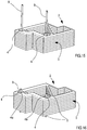
- the first module 2 exhibits, along the stratification direction D, a substantially constant cross-section essentially defining a profiled element. More particularly, the first module 2 exhibits, along a cross-section perpendicular to the stratification direction D, a closed outer perimeter having, for example, a polygonal shape (see Figure 9 for example).
- the first module 2 comprises an internally hollow body; particularly, the first module 2 comprises at least one seat defined inside the closed outer perimeter, which develops for all the extension of said first module 2 along the stratification direction D: the through seat extends between the first and second ends of the module 2.
- the through seat extends between the first and second ends of the module 2.
- at least part of the outer lateral surface 3a of the first module 2 defines a reciprocal coupling surface 3b which, as will be better described in the following, is configured for abutting on a respective reciprocal coupling surface of a further module.
- the lateral surface 3a of the first module 2 can define a further reciprocal coupling surface 3c opposite to the reciprocal coupling surface 3b of the module 2 itself.
- the further reciprocal coupling surface 3c of the first module 2 exhibits the same shape and size as the reciprocal coupling surface 3b of the module 2 itself; the further reciprocal coupling surface 3c of the first module is configured for abutting on a reciprocal coupling surface and/or on a further reciprocal coupling surface of a further module.
- the first module 2 comprises at least one hooking portion 4 defining at least one cavity 4a extending at least partially along the stratification direction D of the module 2 itself.
- the hooking portion 4 is defined inside said closed outer perimeter; optionally the portion 4 extends for all the development of the first module 2 along the stratification direction D, in other words from the first to the second ends of the first module 2.
- Figures 1 , 3 and 4 illustrate in a non-limiting way a first module 2 exhibiting two hooking portions 4.
- Figure 2 illustrates an embodiment variant wherein the first module 2 exhibits only one hooking portion 4. However, it is not excluded the possibility of making a first module 2 exhibiting a number of hooking portions 4 greater than 2.
- the first module 2 can exhibit a number of hooking portions 4 equal to or comprised between 1 and 10, particularly between 1 and 5, still more particularly between 1 and 4.
- Each hooking portion 4 can define only one cavity 4a or a plurality of cavities in a number for example comprised between 1 and 4.
- the first module 3 can comprise - inside the closed outer perimeter - a reinforcing portion 11 extending inside the closed outer perimeter between two sides substantially opposite to each other.
- the reinforcing portion 11 of the first module 2 extends along the stratification direction D along all the development of the first module 2, particularly from the first to the second ends of the first module 2.
- the reinforcing portion 11 defines, cooperatively with the lateral wall 3 of the first module 2, at least one first and one second flanked through seats 12, 13 and both defined inside the closed outer perimeter of the first module 2 (see Figures 1 and 9 for example).
- the first module 2 can exhibit a height - defined along the stratification direction D - greater than 100 mm, particularly greater than 200 mm, still more particularly comprised between 250 and 1,000 mm. Moreover, the first module can exhibit a length and a width - measured perpendicular to the stratification D and perpendicular to each other - greater than 100 mm, particularly greater than 200 mm, still more particularly comprised between 250 and 3,000 mm.
- the structure 1 comprises at least one module 5 externally delimited by a lateral wall 6 which defines an outer lateral surface 6a of the second module 5.
- the lateral wall 6 of the second module 5 extends along a stratification direction between a first and second ends; the stratification direction, as will be better described in the following, is a direction along which the three-dimensional printing process deposits a plurality of layers L of cementitious material one on the other ( Figures 10 and 11 ).
- the stratification direction D of the first module 2 and the stratification direction of the second module 5 are parallel to each other.
- the second module 5 exhibits, along the stratification direction, a substantially constant cross-section essentially defining a profiled element.
- the second module 5 exhibits, along a cross-section perpendicular to the stratification direction, a closed outer perimeter having a polygonal shape for example.
- the second module 5 comprises an internally hollow body; particularly, the second module 5 comprises at least one seat defined inside the closed outer perimeter which extends for all the extension of said second module along the stratification direction: the through seat extends between the first and second ends of the module 5.
- At least part of the outer lateral surface 6a of the second module 5 defines a reciprocal coupling surface 6b countershaped and in contact with the reciprocal coupling surface 3b of the first module 2.
- the lateral surface 6a of the second module 5 can define a further reciprocal coupling surface 6c opposite to the reciprocal coupling surface 6b of the module 5 itself.
- the further reciprocal coupling surface 6c of the second module 5 exhibits the same shape and size as the reciprocal coupling surface 6b of the module 5 itself; the further reciprocal coupling surface 6c of the second module 5 abuts on a reciprocal coupling surface and/or on a further reciprocal coupling surface of a further module.
- the second module 5 comprises at least one hooking portion 7 defining at least one cavity 7a extending at least partially along the stratification direction of the module 5.
- the hooking portion 7 is defined inside said closed outer perimeter; optionally, the portion 7 extends for all the development of the second module 5 along the stratification direction, in other words from the first to the second ends of the second module 5.
- Figures 1 and 3 illustrate, in a non-limiting way, a second module 5 exhibiting two hooking portions 7.
- Figure 2 illustrates an embodiment variant wherein the second module exhibits three hooking portions 7. However, it is not excluded the possibility of making the second module 5 so that is has only one hooking portion 7 or a number of hooking portions 7 greater than three.
- the second module 5 can exhibit a number of hooking portions 7 equal to or comprised between 1 and 10, particularly between 1 and 5, still more particularly between 1 and 4.
- Each hooking portion 7 can define only one cavity 7a or a plurality of cavities, for example in a number comprised between 1 and 4.
- the second module 2 can comprise - inside the closed outer perimeter - a reinforcing portion 14 which extends inside the closed outer perimeter between two sides substantially opposite to each other.
- the reinforcing portion 14 of the second module 5 extends along the stratification direction for all the development of the second module 5, particularly from the first to the second ends of the module 5.
- the reinforcing portion 14 defines, cooperatively with the lateral wall 6 of the second module 5, at least one first and one second flanked through seats 15, 16 and both defined inside the closed outer perimeter of the second module 5 (see Figures 1 and 3 , for example).
- the second module 5 can exhibit a height - defined along the stratification direction of the module 5 itself - greater than 100 mm, particularly greater than 200 mm, still more particularly comprised between 250 and 1,000 mm.
- the first and second modules 2, 5 exhibit substantially the same height: the first and second ends of the first module are respectively disposed at the first and second ends of the second module 5.
- the second module 5 can exhibit a length and width - measured perpendicularly to the stratification direction of the module 5 itself and perpendicular to each other - greater than 100 mm, particularly greater than 200 mm, still more particularly comprised between 250 and 3,000 mm.
- Figure 1 illustrates - in a non-limiting way - an embodiment of the structure 1 wherein the first and second modules 2, 5 are identical to each other by shape and size.
- the structure 1 can comprise, in a non-limiting way, at least one third module 18 externally delimited by a lateral wall 19 which defines an outer lateral surface 19a of the third module 18.
- the lateral wall 19 of the third module 18 extends along a stratification direction between a first and second ends; the stratification direction, as will be better described in the following, is a direction along which the three-dimensional printing process deposits a plurality of layers L of cementitious material one on the other.
- the stratification direction of the first and second modules 2, 5 is parallel to the stratification direction of the third module 18.
- the third module 18 exhibits, along the stratification direction, a substantially constant cross-section essentially defining a profiled element. More particularly, the third module 18 exhibits, along a cross-section perpendicular to the stratification direction, a closed outer perimeter having a polygonal shape for example.
- the third module 18 comprises an internally hollow body; particularly, the second third 18 comprises at least one seat defined inside the closed outer perimeter which extends for all the extension of said second module along the stratification direction: the through seat extends between the first and second ends of the module 18.
- At least part of the outer lateral surface 19a of the third module 18 defines a reciprocal coupling surface 19b countershaped to and in contact with the further reciprocal coupling surface 6c of the second module 5. As it is visible in Figures from 1 to 3, for example, at least part of the lateral surface 19a of the third module 18 can define a further reciprocal coupling surface 19c opposite to the reciprocal coupling surface 19b of the module 18 itself.
- the further reciprocal coupling surface 19c of the third module 18 exhibits the same shape and size as the reciprocal coupling surface 19b of the module 18 itself; the further reciprocal coupling surface 19c of the third module 18 abuts on a reciprocal coupling surface and/or a further reciprocal coupling surface of a further module.
- the third module 18 comprises at least one hooking portion 20 defining at least one cavity 20a extending at least partially along the stratification direction of the module 18.
- the hooking portion 20 is defined inside said closed outer perimeter; optionally the portion 20 extends for all the development of the third module 18 along the stratification direction, in other words from the first to the second ends of the third module 18.
- Figures 1 and 3 illustrate in a non-limiting way a third module 18 exhibiting two hooking portions 20.
- Figure 2 illustrates an embodiment variant wherein the third module exhibits three hooking portions 20.
- the third module 18 can exhibit a number of hooking portions 20 equal to or comprised between 1 and 10, particularly between 1 and 5, still more particularly between 1 and 4.
- Each hooking portion 20 can define only one cavity 20a or a plurality of cavities, for example in a number comprised between 1 and 4.
- the third module 18 can comprise - inside the closed outer perimeter - a reinforcing portion 21 extending inside the closed outer perimeter between two sides substantially opposite to each other.
- the reinforcing portion 21 of the third module 18 extends along the stratification direction for all the development of the third module 18, particularly from the first to the second ends of the module 18.
- the reinforcing portion 21 defines, cooperatively with the lateral wall 19 of the third module 18, at least one first and one second flanked through seats 22, 23 both defined inside the closed outer perimeter of the third module 18 (see Figure 3 , for example).
- the third module 18 can exhibit a height - defined along the stratification direction of the module 18 itself - greater than 100 mm, particularly greater than 200 mm, still more particularly comprised between 250 and 3,000 mm.
- the second and third modules 5, 18 exhibit substantially the same height (so that the third module exhibits substantially the same height as the first module) : the first and second ends of the second module are respectively disposed at the first and second ends of the first module 18.
- the third module 18 can exhibit a length and width - measured perpendicularly to the stratification direction of the module 18 itself and perpendicularly to each other - greater than 100 mm, particularly greater than 200 mm, still more particularly comprised between 250 and 3,000 mm.
- Figure 1 illustrates an embodiment of the structure wherein the first and second modules 2, 5 are identical to each other by shape and size, while the third module exhibits a shape and size different from said modules 2 and 5.
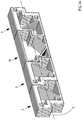
- the structure 1 can comprise a plurality of modules in contact with each other and aligned along a direction A (see Figure 14 for example) perpendicular to a stratification direction of each module.
- the structure 1 can comprise a number of modules greater than 3; particularly the structure 1 can comprise a number of modules greater than 4, particularly greater than 5, still more particularly comprised between 5 and 20.
- At least part of the plurality of modules of the structure 1 can comprise a reciprocal coupling surface and a further reciprocal coupling surface opposite to each other with respect to the module itself; the reciprocal coupling surface of a module abuts on a reciprocal coupling surface and/or on a further reciprocal coupling surface of an immediately adjacent module (modules in contact with each other).
- the modules can be all different from each other by shape and size or can be at least partially identical to each other by shape and size.
- the shape and/or size of the above described modules can be determined by a process optimizing the topology, which maximizes the mechanical performance of the block.
- the structure comprises at least one connecting element 8 engaged, on one side, inside the cavity 4a of the hooking portion 4 of the first module 2 and, on the other side, inside the cavity 7a of the hooking portion 7 of the second module 5: the connecting element 8 stably constrains the first and second modules 2, 5 and is configured for holding these latter in contact with each other.
- the connecting element acts as an outer reinforcing element providing the structure with strength to tensile loads.
- the connecting element 8 comprises at least one reinforcing bar, optionally of metal material, extending along a longitudinal development direction between a first and second end portions 8a, 8b: the longitudinal development direction of the bar is transversal, particularly perpendicular, to the stratification direction of the first and second modules.
- the connecting element 8 comprises - at the first end portion 8a - a first engagement portion 9 emerging from the reinforcing bar transversally to the longitudinal development direction of the same and engaged inside the cavity 4a of the hooking portion 4 of the first module 2.
- the connecting element 8 comprises - at the second end portion 8b - a second engagement portion 10 emerging from the reinforcing bar transversally to the longitudinal development direction of the same and engaged inside the cavity 7a of the hooking portion 7 of the second module 2.
- the portions 9 and 10 partially cross - along the height - the first and second modules 2, 5 while the reinforcing bar is disposed outside the lateral wall and the through seat of the respective modules.
- the reinforcing bar is essentially an outer connecting bar between the portions 9, 10 which are engaged inside the respective modules; the bar essentially acts as a tie in relation to the tensile stresses generated in the system.
- the connecting element 8 can comprise only one reinforcing bar adapted to connect the engagement portions 9 and 10.
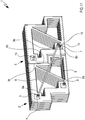
- Figures 5 and 6 illustrate a preferred embodiment of the connecting element 8 which exhibits a first and second engagement portions 9, 10 vertically crossing the first and second modules and exhibiting respective end portions emerging from the first and second ends of the respective modules ( Figure 5 ).
- the connecting element 8 exhibits two reinforcing bars disposed at the first and second ends of the module 2 and 5: the bars are disposed opposite to each other with respect to the modules 2 and 5.
- a first reinforcing bar is constrained to the first end portion of the portions 9 and 10 while a second bar is constrained to the second end portion of the portions 9 and 10. Both the reinforcing bars are disposed outside the modules 2, 5 and respectively at the first and second ends of these latter.
- Figure 2 illustrates an embodiment of the structure 1, comprising only one connecting element 8 adapted to constrain the first and second modules 2.
- Figure 1 illustrates a preferred but non-limiting embodiment of the invention wherein the structure comprises two connecting elements adapted to stably constrain the first and second modules 2, 5. However it is not excluded the possibility of defining a structure 1 comprising a number of connecting elements 8 equal to or greater than 3, particularly comprised between 3 and 10, still more particularly between 3 and 5.
- the first and second engagement portions 9, 10 of the connecting element 8 are distinct and removably associable to the reinforcing bar.
- the first and second engagement portions 9, 10 can for example comprise respective threaded bars:
- the reinforcing bar can comprise, for example, a bar exhibiting at the end portions 8a, 8b an engagement portion shaped as an eyelet or slot inside which part of the threaded bar of the portions 9 and 10 can be housed.
- the reinforcing bar can be fixed to the respective engagement portions by bolts engaging the threaded bars of the portions 9 and 10 and which therefore constrain the engagement portions of the reinforcing bar to the portions 9 and 10.
- Figure 18 illustrates an embodiment variant of the connecting element wherein the reinforcing bar and engagement portions 9, 10 are integrally joined for defining a single body having a substantially "C" shape.
- the structure 1 can comprise at least one connecting element 24 engaging, on one side, inside the cavity 7a of the hooking portion 7 of the second module and, on the other side, inside the cavity 20a of the hooking portion 20 of the third module 18: the connecting element 24 stably constrains the second and third modules 5, 18, and is configured for holding these latter in contact with each other.
- the connecting element 24 comprises at least one reinforcing bar, optionally of metal material, extending along a longitudinal development direction between a first and second end portions 24a, 24b: the longitudinal development direction of the bar is transversal, particularly perpendicular, to the stratification direction of the first and second modules.
- the connecting element 24 comprises - at the first end portion 24a - a first engagement portion 25 emerging from the reinforcing bar transversally to the longitudinal development direction of the same and engaged inside the cavity 7a of the hooking portion 7 of the second module 5 ( Figure 3 ).
- the connecting element 24 further comprises - at the second end portion 24b - a second engagement portion 26 emerging from the reinforcing bar transversally to the longitudinal development direction of the same and engaged inside the cavity 20a of the hooking portion 20 of the third module 18.
- the portions 25 and 26 vertically cross at least partially the second and third modules 5, 18 while the reinforcing bar is disposed outside the lateral wall and the through seat of the respective modules.
- the reinforcing bar of the element 24 is essentially an outer connecting bar between the portions 25, 26 which are engaged inside the respective modules.
- the connecting element 24 can comprise only one reinforcing bar adapted to connect the engagement portions 25 and 26.
- the connecting element 24 exhibits a first and second engagement portions 25, 26 vertically crossing the second and third modules and exhibiting respective end portions emerging from the first and second ends of the respective modules. With such arrangement, the connecting element 24 exhibits two reinforcing bars disposed at the first and second ends of the modules 5 and 18: the bars are disposed opposite to each other with respect to the modules 5 and 18.
- a first reinforcing bar is constrained to the first end portions of the portions 25 and 26, while a second bar is constrained to the second end portion of the portions 25 and 26. Both the reinforcing bars are disposed outside the modules 5 and 18 and respectively at the first and second ends of these latter.
- the structure 1 can comprise only one connecting element 24 adapted to constrain the second and third modules 5, 18 ( Figure 2 ).
- Figure 1 illustrates a preferred but non-limiting embodiment of the invention wherein the structure comprises two connecting elements 24 adapted to stably constrain the second and third modules 5, 18.
- the first and second engagement portions 25, 26 of the connecting element 24 are distinct and removably associable to the reinforcing bar.
- the first and second engagement portions 25, 26 can for example comprise respective threaded bars:
- the reinforcing bar can for example comprise a bar exhibiting, at the end portions 24a, 24b, an engagement portion shaped as an eyelet or slot inside which part of the threaded part of the portions 25 and 26 can be housed.
- the reinforcing bar can be fixed to the respective engagement portions by bolts which engage the threaded bars of the portions 25 and 26 which constrain therefore the engagement portions of the reinforcing bar to the portions 25 and 26.
- the structure 1 comprises at least one connecting element 27 engaged, on one side, inside the cavity 4a of the hooking portion 4 of the first module 2 and, on the other side, inside the cavity 20a of the hooking portion 20 of the third module 18; the connecting element 27 stably constrains the first module and third module 2, 18.
- the connecting element exhibits an arrangement (structure) similar to the connecting elements 8 and 24.
- the structure 1 is configured for mainly opposing, under operative conditions of the same, a stress S directed perpendicularly to the stratification direction of the plurality of modules and perpendicularly to the alignment direction A of the same (the direction A is schematically shown in Figure 14 ).
- the process comprises a step of making a plurality of modules of cementitious material by a three-dimensional printing process which comprises a step of depositing a plurality of layers L of cementitious material one on the other along a stratification direction D; the layers L exhibit substantially the same shape and size: each module can exhibit, along the stratification direction D, a substantially constant cross-section for essentially defining a profile.
- FIG. 10 schematically illustrate the three-dimensional printing process of making the first module 2.
- the head 101 of the 3D printer deposits one layer L on another layer of cementitious material for defining a cross-section of the module.
- the second module 5 the configuration thereof is not illustrated in the attached figures
- optionally the third module 18 are made.
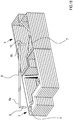
- the process comprises a step of contacting the second and third modules so that the further reciprocal coupling surface 6c of the second module 5 abuts on the reciprocal coupling surface 19b of the third module 18 ( Figure 13 illustrates a step of approaching the modules 5 and 18).
- the process comprises a step of engaging at least one connecting element 8, from one side, inside the cavity 4a of the hooking portion 4 of the first module 2 and, on the other side, inside the cavity 7a of the hooking portion 7 of the second module 5; the connecting element 8 stably constrains the first and second modules 2, 5 and is configured for holding these latter in contact with each other. More specifically, the step of engaging the connecting element 8 to the first and second modules 2, 5 comprises at least the following sub-steps:
- Figure 18 illustrates a step of inserting the connecting element 8 comprising the engagement portions 9, 10 integrally joined to the reinforcing bar.
- the connecting element 8 can comprise engagement portions 9, 10 distinct and removable from the reinforcing bar; in such arrangement, the step of engaging the connecting element 8 comprises the following sub-steps:
- the process comprises a step of constraining (fixing) the reinforcing bar to said first and second engagement portions 9, 10.
- the process simultaneously with or after the step of engaging the connecting element 8 with the first and second modules, can comprise at least one step of further fixing the first and second modules which comprises at least the following sub-steps:
- the process can comprise a step of engaging at least one connecting element 24, on one side, inside the cavity 7a of the hooking portion 7 of the second module 5 and, on the other side, inside the cavity 20a of the hooking portion 20 of the third module 18; the connecting element 24 stably constrains the second module 5 and third module 18 and is configured for holding these latter in contact with each other. More specifically, the step of engaging the connecting element 24 with the second and third modules comprises at least the following sub-steps:
- the connecting element 24 can comprise engagement portions 25 distinct and removable from the reinforcing bar; in such arrangement, the step of engaging the connecting element 24 comprises the following sub-steps:
- the process comprises a step of constraining (fixing) the reinforcing bar to said first and second engagement portions 25 and 26.
- the process simultaneously with or after the step of engaging the connecting element 24 with the second and third modules, can comprise at least one step of further fixing the first and second modules which comprises at least the following sub-steps:
- the process can comprise a step of engaging at least one connecting element 27 (the structure thereof can be identical to the connecting elements 8 and/or 24, for example), on one side, inside the cavity 4a of the hooking portion 4 of the first module 2 and, on the other side, inside the cavity 20a of the hooking portion 20 of the third module 18: the connecting element 27 stably constrains the first module and third modules 2, 18.
- at least one connecting element 27 the structure thereof can be identical to the connecting elements 8 and/or 24, for example
- a cementitious composition comprising cement, an inert aggregate, a polymeric fiber, a superfluidifying agent and water, characterized by specific quantities of the components, by the ratio between the water quantity and cement quantity, by the quantity of the superfluidifying agent and by the granulometry of the inert aggregate, is particularly adapted to make structures of reinforced cementitious material by the 3D printing process of the present invention.
- the present inventors starting from the water/cement ratio necessary to obtain the required mechanical performance and the required setting and hardening kinetics, have optimized the consistency of the mixture by using a fluidifying agent having a specific quantity in relation with the granulometry and capable of absorbing the inert aggregate. Therefore, a further aspect of the disclosure is a cementitious composition M comprising:
- a suitable cement is selected among those belonging to the types I, II, III, IV and V, established by the standard EN 197-1, accepted at a national level by the standard UNI EN 197/1.
- a suitable cement is selected among those belonging to the types I, II, III, IV and V and having strength classes 42,5R and 52,5R according to the standard UNI EN 197/1.
- a suitable cement is selected among the cements belonging to the classes CEM II/A-L (or A-LL) 42,5R and CEM II/A-L (or A-LL) 52,5R; more preferably selected among the cements belonging to the class CEM II/A-L (or A-LL) 42,5R according to the standard UNI EN 197/1.
- said suitable cement has a maximum diameter of the particles less than or equal to 100 microns, preferably less than 50 microns, still more preferably less than 30 microns.
- the percentage by weight of cement is preferably greater than 18%, more preferably greater than 21%; and/or is preferably less than 27%, more preferably is less than 25%; and/or is preferably comprised between 18% and 27%, more preferably is comprised between 21% and 25% with respect to the total weight of the composition.
- part of the cement can be substituted with II type additions according to the standard UNI EN 206-1:2006, and particularly with silica fume, or fly ashes, or blast furnace slag, or pozzolana both natural and industrial, comprised between 1 and 3% by weight with respect to the total weight of the composition, preferably silica fume comprised between 1 and 3% by weight with respect to the total weight of the composition; in this case such additions of II type substitute part of the cement by a percentage comprised between 7 and 11% by weight of the cement.
- the "weight ratio between water and cement” it is considered the "weight ratio between water and equivalent cement" as established by the standard UNI EN 206-1: 2006, according to the following formula:
- the water/cement ratio of the cementitious composition of the present disclosure wherein from 7 to 11% by weight of the cement is substituted with II type additions is comprised between 0.29 and 0.49.
- the at least one suitable inert aggregate is selected among fine aggregates, filler and mixtures thereof; preferably the filler is selected in case of I type additions according to the standard UNI EN 12620, more preferably the filler is selected between quartz sand, siliceous sand (microsilica) and calcareous filler (calcium carbonate).
- the composition comprises a mixture of inert aggregates; more preferably comprises sand and quartz sand and/or calcareous filler.
- said sand is from 90% to 95% and said filler, preferably quartz sand or calcareous filler, is from 5% to 10% with respect to the total weight of the inert aggregates.
- said sand has a maximum diameter less than 10 mm, still more preferably less than 6 mm, still more preferably less than 4 mm, according to the standard UNI 8520-1 for the compliance, and according to the standard UNI 2332 for determining the granulometric distribution.
- said filler preferably quartz sand or calcareous filler, has a maximum diameter less than 0.25 mm, preferably less than 0.125 mm, still more preferably less than 0.063 mm according to the standard UNI 8520-1 for the compliance and according to the standard UNI 2332 for determining the granulometric distribution.
- the percentage by weight of the at least one inert aggregate, alone or in a mixture with one or more other inert aggregates is preferably greater than 63%, more preferably greater than 65%, and/or is preferably less than 79%, more preferably is less than 77%; and/or is preferably comprised between 63% and 79%, more preferably is comprised between 65% and 77% with respect to the total weight of the composition.
- said at least one polymeric fiber is selected among polyolefinic fibers, preferably polypropylene (PP); polyvinyl alcohol (PVA); polyesters; aliphatic polyamides (Nylon); and mixtures thereof.
- said at least one polymeric fiber is a polypropylene fiber (PP).
- said at least one polymeric fiber, more preferably polypropylene (PP) has a diameter or a maximum size of the cross-section comprised between 0.12 and 0.8 mm, more preferably comprised between 0.25 and 0.35 mm.
- said at least one polymeric fiber, more preferably polypropylene (PP) has a length less than 60 mm, more preferably comprised between 10 and 57 mm, still more preferably between 40 and 55 mm.
- the percentage by weight of the at least one polymeric fiber, alone or in a mixture with one or more other polymeric fibers is preferably greater than 0.025%, more preferably greater than 0.03%; and/or is preferably less than 0.6%, more preferably is less than 0.5%; and/or is preferably comprised between 0.025% and 0.6%, more preferably is comprised between 0.03% and 0.5% with respect to the total weight of the composition.
- Suitable polymeric fibers can be selected among those commercially available, for example those of the MapeFibre series marketed by Mapei, for example MapeFibre CN54 or NS12; those of the series RUREDIL marketed by RUREDIL, for example RUREDIL X FIBER 19; those of the Polifer series marketed by Polifer, for example Polifer 420. Without wishing to be bound by any explicative theory, the present inventors deem that said polymeric fibers have the function of contributing to the continuity of the flow of said composition exiting the supplying head 101, of providing the not already hardened slurry with tenacity and of decreasing the shrinkage effect of the cementitious composition.
- said at least one superfluidifying agent is selected among polymers optionally modified polycarboxylic polyethers, naphthalene sulfonic polyethers, polyphosphonics polyethers, acrylic polyethers, and polypropylene glycols, and mixtures thereof.
- said at least one superfluidifying agent is a polymer possibly a modified polycarboxylic polyether.
- said at least one fluidifying agent can be present as dust or in a liquid form, for example in an aqueous solution; preferably as dust, said dust has a density comprised between 50 and 80 g/100 cm 3 , preferably comprised between 30 and 60 g/100 cm 3 .
- Suitable superfluidifying agents are selected among those commercially available, for example among those of the Melflux® series marketed by BASF, such as for example Melflux® 2651F, and those of the series Dynamon® marketed by Mapei.
- the percentage by weight of the at least one superfluidifying agent, alone or in a mixture with one or more other fluidifying agents, is preferably greater than 0.035%; and/or is preferably less than 0.05%; and/or is preferably comprised between 0.035% and 0.05% with respect to the total weight of the composition.
- the percentage by mass of the at least one superfluidifying agent, alone or in a mixture with one or more other fluidifying agents, is preferably greater 0.02%, more preferably greater than 0.05%; and/or is preferably less than 0.15%, more preferably is less than 0.10%; and/or is preferably comprised between 0.02% and 0.15%, more preferably is comprised between 0.05% and 0.10% with respect to the total mass of the composition.
- the percentage by mass of the at least one superfluidifying agent, alone or in a mixture with one or more other fluidifying agents, is preferably greater than 0.1%, more preferably greater than 0.2%, still more preferably greater than 0.25%; and/or less than 0.65%, more preferably less than 0.5%, still more preferably less than 0.40%; and/or is comprised between 0.1% and 0.65%, more preferably is comprised between 0.2% and 0.5%, still more preferably is comprised between 0.25% and 0.40% with respect to the total mass of the cement.
- the present inventors deem that the superfluidifying agent, added with specific quantities at the end of the mixing step in a mixer, adjusts the rheology and thixotropy of the cementitious composition. Particularly, such superfluidifying agent determines a low viscosity during the supplying step by the supplying head 101, for ensuring the printability of the cementitious composition, at the same time determines a high viscosity after the deposition of the composition in order to ensure in this way to separate the layers and support the layers successively deposited by the printing process.
- the present inventors have noted that the superfluidifying dust is better distributed in the mixture and exerts the fluidifying effect in very few minutes after introducing it in the mixer (the effect is visible since it makes homogeneous and "pasty" the mixture).
- the weight ratio between water and cement is comprised between 0.33 and 0.40.
- the cementitious composition can optionally comprise: natural or synthetic fibers besides those listed at the point (iii), for example short fibers of hemp, flax, jute; aerating agents, for example the Mapeair AE series marketed by Mapei; lightened inert aggregates having a maximum diameter less than 12.5 mm, such as for example Leca expanded (structural) clays; geopolymeric binders based on metakaolin and an aqueous solution of metal hydroxides (for example sodium hydroxide), such as for example setting accelerators, such as for example the Mapequick series of Mapei; hollow glass nanospheres.
- the cementitious composition - according to the further aspect of the present disclosure - comprises:
- the cementitious composition comprises:
- the cementitious composition comprises:
- the cementitious composition falls into a consistency class S1.
- said composition in a green state has a value of the Abrams cone slump test (SLUMP), measured according to the standard EN 12350-2:2009, comprised between 10 and 40 mm, preferably comprised between 30 and 40 mm.
- the cementitious composition according to the present disclosure hardened after curing for 28 days, has an average cubic strength value R cm and an average cylindrical strength f cm , measured according to the standard EN 12390, comprised respectively between 50 and 60 MPa and between 40 and 48 MPa.
- a further aspect of the present disclosure comprises a method of preparing the cementitious composition according to the present disclosure, comprising:
- a suitable cement is selected among those belonging to the types I, II, III, IV and V, established by the standard EN 197-1, accepted at a national level by the standard UNI EN 197/1.
- a suitable cement is selected among those belonging to the types I, II, III, IV and V and having strength classes 42, 5R and 52,5R according to the standard UNI EN 197/1.
- a suitable cement is selected among those cements belonging to the classes CEM II/A-L (or A-LL) 42,5R and CEM II/A-L (or A-LL) 52,5R; more preferably selected among the cements belonging to the class CEM II/A-L (or A-LL) 42,5R according to the standard UNI EN 197/1.
- Said suitable cement has a maximum diameter of the particles less than or equal to 100 microns, preferably less than 50 microns, still more preferably less than 30 microns.
- the at least one suitable inert aggregate is selected among sand, filler and mixtures thereof, preferably the filler is selected in the family of the I-type additives according to the standard UNI EN 12620, more preferably the filler is selected among quartz sand, silica sand (microsilica), and calcareous filler.
- said sand has a maximum diameter less than 12.5 mm, preferably less than 10 mm, still more preferably less than 6 mm, still more preferably less than 4 mm, according to the standard UNI 8520-1 for the compliance and according to the standard UNI 2332 for determining the granulometric distribution.
- said filler preferably quartz sand or calcareous filler, has a maximum diameter less than 0.25 mm, preferably less than 0.125 mm, still more preferably less than 0.063 mm, according to the standard UNI 8520-1 for the compliance and according to the standard UNI 2332 for determining the granulometric distribution.
- said at least one polymeric fiber is selected among polyolefinic fibers, preferably polypropylene (PP), polyvinyl alcohol (PVA); polyesters; aliphatic polyamides (Nylon); and mixtures thereof.
- said at least one polymeric fiber is a polypropylene (PP) fiber.
- said at least one polymeric fiber, more preferably a polypropylene (PP) fiber has a diameter or a maximum dimension of the cross-section comprised between 0.12 and 0.8 mm, more preferably comprised between 0.25 and 0.35 mm.
- said at least one polymeric fiber, more preferably polypropylene (PP) has a length less than 60 mm, more preferably comprised between 10 and 57 mm, still more preferably between 40 and 55 mm.
- said at least one superfluidifying agent is selected among polymers optionally modified polycarboxylic polyethers, naphthalene sulfonic polyethers, polyphosphonic polyethers, acrylic polyethers, polypropylene glycols and mixtures thereof.
- said at least one superfluidifying agent is a polymer possibly a modified polycarboxylic polyether.
- the mixing steps from a) to d) are performed at a speed comprised between 20 and 60 rounds per minute, more preferably between 30 and 50 rounds per minute.
- the mixing step a) and c) is extended for a time comprised between 10 seconds and 10 minutes, preferably between 1 minute and 7 minutes, more preferably between 2 minutes and 5 minutes.
- the mixing step b) is extended for a time comprised between 10 seconds and 10 minutes, preferably between 1 minute and 7 minutes, more preferably between 2 minutes and 5 minutes in which all the quantity of water is added; after adding water, the mixing step is extended for a time comprised between 10 seconds and 15 minutes, preferably between 1 minute and 10 minutes, more preferably between 2 minutes and 7 minutes.
- the mixing step d) is extended for a time comprised from 20 seconds to 20 minutes, preferably between 1 minute and 15 minutes, more preferably between 2 minutes and 13 minutes.
- cementitious composition according to the invention for 3D printing modules/structures of reinforced cementitious material.
- step a 40 liters of a cementitious composition are prepared.
- step a about 57.2 kg of sands (maximum diameter: 2 mm) and about 3.98 kg of quartz sand (maximum diameter: 0.125 mm) corresponding respectively to 1,431 kg and 99.5 kg per cubic meter of the final cementitious composition, are introduced into a cylindrical type electric mixer having a maximum capacity of 140 liters, beforehand wetted to saturation.
- step a about 19.9 kg of CEM II/A-LL 42.5 R corresponding to 498 kg per cubic meter of the final cementitious composition are added into the mixer, and then the dry powders are mixed for about 3 minutes, at a rotation speed of the mixer of about 40 rounds per minute.
- step b) water is gradually added, for a total of about 7 liters corresponding to 176.5 liters per cubic meter of the final cementitious composition, by mixing for a time corresponding to the addition of all the water quantity, corresponding to about 3 minutes at a rotation speed of the mixer of about 40 rounds per minute; then, the mixing step is extended for about other 5 minutes under the above given same rotation speed conditions of the mixer.
- polypropylene fibers MapeFibre CN54, marketed by Mapei
- polypropylene fibers MapeFibre CN54, marketed by Mapei
- step d a quantity of 0.069 kg corresponding to 1.74 kg per cubic meter of the final cementitious composition, of the superfluidifying additive based on a modified polycarboxylic polyether (Melflux® 2651F marketed by BASF) is gradually added (1/3 + 1/3 + 1/3), and is mixed for further 5-10 minutes.
- a modified polycarboxylic polyether (Melflux® 2651F marketed by BASF)
- the consistency class was measured by the Abrams cone, consisting of a cone made of galvanized steel or stainless steel having a thickness of about 1.5 mm and having a frustoconical shape with the following internal dimensions:
- the composition described in the example 1 in a green state (before being inserted in the printer) was quickly introduced and completely packed in the frustoconical container by following the suggestions of the cited standard.
- the slum of the Abrams cone of the cementitious composition of the invention in a green state was 34 mm, in other words said cementitious composition falls into the consistency class S1.
- the average cubic strength R cm and the average cylindrical strength f cm under an uniaxial compression (by controlling the force) were measured on normalized specimens and therefore respectively on 4 cubic samples having a side of 150 mm and on 4 cylindrical samples having a diameter of 150 mm and a height of 300 mm.
- cementitious composition in a green state exhibits an optimal consistency, consequently such cementitious composition exhibits an optimal capacity of being supplied through the supplying head 101 and of remaining separated in layers and supporting the gradually printed layers.
- hardened cementitious composition has an optimal capacity of opposing to the compression, therefore is capable of compensating possible weaknesses of the connecting points between adjacent layers.
- the average compression strength, if calculated on the average surface of the cross-section (f cpm ) of the three tested construction elements C1, C2 and C3, is 16% less than the average cylindrical strength f cm of the cementitious composition used for 3D-printing the construction element (37.2 MPa vs 44.4 MPa).
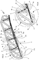
- the cementitious composition was used for preparing, from a determined 2D profile, a three-dimensional structure (INV) long 3.20 m having an overall rectangular cross-section with a width of 0.20 m and a height of 0.40 m, formed by 7 modules, made by the 3D-printing process of the present invention, as shown in Figure 1 .
- the weight of the three-dimensional structure (INV) corresponds to 45% of the weight of the equivalent solid structure (RIF), the cross-section thereof has the same dimensions, in other words 0.20 m and 0.40 m, and the same longitudinal steel reinforcement, in other words two bars with a diameter of 10 mm and a cover of 40 mm.
- the flexural rigidity of both structures (INV) and (RIF) was calculated for understanding the possibilities of this technology of designing and printing a beam obtained by modules having a particular shape, as shown in Figure 1 .
- the deflection f (or transversal displacement of the axis) of the beam of the structure (INV) was measured at the midline cross-section of the same, under the effect of the own load of the structure abutting on two ends.
- the measurement was performed by a decimal comparator.
- Table 2 shows the flexural rigidity values E I of the three-dimensional structure of the invention (INV) and of said equivalent solid structure (RIF) when is uncracked (RIF1, the percentage of cracks is less than 50%) and when is cracked (RIF2, the percentage of cracks is greater than 60%).
- Table 2 Structure E I N/mm 2 INV 1.20 ⁇ 1013 RIF1 2, 6 ⁇ 10 13 RIF2 0.13 ⁇ 10 13
- the flexural rigidity value of the structure of the invention is intermediate between the one of the solid uncracked structure (RIF1) and of the cracked one (RIF2), this latter was evaluated according to the "Norme Tecniche per le Costruzioni (NTC2008)".
- the cementitious composition characterized by the specific quantity of components from (i) to (v), particularly characterized by the ratio between the water quantity and cement quantity, by the quantity of superfluidifying agents and by the granulometry of the inert aggregates, is particularly suitable for making structures of reinforced cementitious material obtained by the 3D printing process of the present invention.
Landscapes
- Engineering & Computer Science (AREA)
- Architecture (AREA)
- Manufacturing & Machinery (AREA)
- Chemical & Material Sciences (AREA)
- Ceramic Engineering (AREA)
- Mechanical Engineering (AREA)
- Civil Engineering (AREA)
- Structural Engineering (AREA)
- Curing Cements, Concrete, And Artificial Stone (AREA)
- Producing Shaped Articles From Materials (AREA)
Description
- The object of the present invention is a structure of reinforced cementitious material and a process of making the same by a three-dimensional printing process. The invention can be advantageously applied in the architectural, design and building fields, for example for erecting buildings and also in the construction engineering field.
- Nowadays, making components by 3D printers using the Additive Manufacturing technology has a blooming development and is substantially impacting different industrial manufacturing fields. The 3D printing process enables to deposit layers of a material on a base of a three-dimensional pattern for physically making this latter. With reference to the present description, the construction, building and design fields are particularly interesting. Recently, the Additive Manufacturing technology is used by 3D printers for supplying inorganic "pastes" (mainly clays) as printing material for making typically small artifacts having non-structural functions. The artifacts obtainable by the Additive Manufacturing technology are not useable as structural elements in the building and construction fields. Until now, the components of cementitious material used in the construction and building fields are made by two different technologies: the subtractive technology and the formative technology. The subtractive technology provides to take away a cementitious material from a rough preform in order to obtain a finished product. On the contrary, the formative technology provides to pour a cementitious material at the liquid (green) state inside adapted moulds (casings) wherein the material solidifies for defining the finished product: at the end of the solidifying step, the finished product is then extracted from the mould. These known technologies, while being widely used for making components and structural elements of cementitious materials, exhibits substantial limitations. De facto, such technologies do not enable to easily and economically make components different from each other by shape and size. Indeed, it is noted that when there is the need of making by the above described processes, different types of blocks of concrete, it will be necessary to differentiate - in case of the subtractive technology - the process of removing the material for each block, while - in case of the formative technology - it will be necessary to provide a different mould for each component; in this way, the actions at a processing level, necessary for making different types of blocks, will substantially increase the times and therefore the costs for manufacturing these latter. Moreover, it is noted that manufacturing blocks different from each other entails, with the subtractive technology, an additional step of processing the rough blocks which, besides increasing the processing times, impacts on the cost and the amount of scraps. Instead, the formative technology requires a greater investment in term of equipment; each type of blocks will require a dedicated mould. Moreover, it is noted that the known above described technologies (subtractive and formative for elements of cementitious material) do not enable to easily and economically make components of cementitious material exhibiting complicated shapes, for example defined by arcuate portions with varying cross-section.
- Therefore, the object of the present invention consists of substantially solving at least one of the inconveniencies and/or limitations of the previous solutions.
- Document
BE463520 FR2918396 -
DE102014206697 discloses a process of making a structure by a three-dimensional printing process of for example cementitious material. - A first object of the present invention consists of providing a structure of reinforced cementitious material exhibiting excellent mechanical properties and, at the same time, easily and quickly manufacturable, in accordance with
claim 6. Particularly, it is an object of the present invention to provide a structure of reinforced cementitious material exhibiting a suitable shape and size and adapted to ensure optimal structural characteristics. Moreover, it is an object of the present invention to provide a structure of reinforced cementitious material which exhibits a flexible use and which can be employed for making different types of constructions and structural elements. Then, it is an object of the present invention to provide a structure of reinforced cementitious material manufacturable with a limited amount of material, and capable anyway of maintaining excellent properties of mechanical strength to stresses. Moreover, it is an object of the present invention to provide a structure of reinforced cementitious material obtainable with limited manufacturing costs. - Then, it is an object of the present invention to provide a fast and highly versatile process of making a structure of reinforced cementitious material which therefore can reduce at the minimum the manufacturing costs, in accordance with
claim 1. - A further object not part of the present invention consists of providing a cementitious composition adapted to be 3D-printed, particularly a cementitious composition being capable of being conveyed to the supplying
head 101 of the 3D printer and to be extruded or pumped by the same, and therefore printable, through the supplying head. - Moreover, a further object not part of the present invention consists of providing a cementitious composition wherein the layers thereof, after being printed, show the capability of remaining separated from each other, and of supporting the weight of the following layers deposited by the 3D printing process, of having a good setting and hardening kinetics, and compressive strength. Lastly, a further object not part of the present invention consists of providing a cementitious composition enabling to make shapes which are both structurally efficient and characterized by using a low quantity of the cementitious material. These and other objects, which will better appear in the following description, are substantially met by a structure of reinforced cementitious material and a process of making this latter according to what is disclosed in one or more of the attached claims, and/or of following aspects, considered alone or in any combination with each other or in a combination with any of the attached claims and/or in a combination of any of the further aspects or characteristics described in the following.
- Some embodiments and some aspects of the invention will be described in the following with reference to the attached drawings, given only in an indicative and therefore non-limiting way, wherein:
-
Figure 1 is a schematic view of a first embodiment of a structure of reinforced cementitious material according to the present invention; -
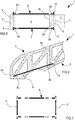
Figure 2 is a schematic view of a second embodiment of a structure of reinforced cementitious material according to the present invention; -
Figure 3 is a schematic view of a third embodiment of a structure of reinforced cementitious material according to the present invention; -
Figure 4 is a detailed view of the structure of reinforced cementitious material ofFigure 3 ; -
Figures 5 and 6 are respectively a top view and a front view of a structure of cementitious material according to the present invention; -
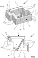
Figure 7 is an exploded view of a connecting element of the reinforced cementitious material according to the present invention; -
Figures 8 and 9 are respectively a perspective view and a front view of a module of a structure of reinforced cementitious material according to the present invention; -
Figures 10 and 11 schematically illustrate a step of forming a module of a structure of reinforced cementitious material according to the present invention; - Figures from 12 to 16 schematically illustrate some steps of a process of making a structure of reinforced cementitious material according to the present invention;
-
Figure 17 is a perspective view of a fourth embodiment a structure of reinforced cementitious material according to the present invention; -
Figure 18 is a perspective view of a step of an embodiment variant of a process of making a structure of reinforced cementitious material according to the present invention; -
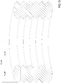
Figure 19 is a cross-section view of a cylindrical specimen used in the example 4. - It is noted that in the present detailed description, corresponding parts illustrated in the different figures are indicated by the same numeral references. The figures could illustrate the object of the invention by not-to-scale representations; therefore, parts and components illustrated in the figures regarding the object of the invention could refer only to schematic representations.
- The term "three-dimensional printing" or 3D printing means a process of making objects by a three-dimensional printer or 3D printer based on a material additive technology (known as Additive Manufacturing). The process provides making - by dedicated modelling software - a three-dimensional model which is delivered to a 3D printer configured for making the corresponding physical model of the digital mathematical model by depositing a material one layer on another, by advancing by cross-sections towards the top.
- The term "3D printer" means a device configured for making a three-dimensional physical model by means of an additive manufacturing 3D-printing process. Particularly, the 3D printer comprises at least one supplying
head 101 configured for depositing a predetermined quantity of material. The 3D printer comprises amovement system 102 connected to the supplyinghead 101 which is configured for moving this latter according to a three-dimensional space. - Moreover, the 3D printer can comprise a
control unit 103 connected to themovement system 102 and to the supplyinghead 101; thecontrol unit 103 is configured for receiving and processing a digital mathematical model and for commanding the activation of themovement system 102 and supplyinghead 101 for defining the stratification (layer-by-layer) of the processed model. The 3D printer is configured, starting from an object designed/drawn by software, for physically reproducing it by suitable materials. - The term "control unit" 103 means an electronic-type component which can comprise at least one of: a digital processor (CPU), a memory (or memories), an analog-type circuit, or a combination of one or more digital processing units with one or more analog-type circuits. The control unit can be "configured" or "programmed" for executing some steps: this can be physically obtained by any means enabling to configure or program the control unit. For example, when a control unit comprises one or more CPUs and one or more memories, one or more programs can be stored in suitable memory banks connected to the CPU or CPUs; the program or programs contain instructions which, when are executed by the CPU or CPUs, program or configure the control unit for executing operations described with reference to the control unit. As an alternative, if the control unit is or comprises an analog-type circuitry, then the circuit of the control unit can be designed to include a configured circuitry, when used, for processing electric signals in order to execute the steps regarding the control unit.
- The term "cementitious material" means a material comprising at least partially a composition of cementitious material, or a cementitious material as specifically described in the following. Particularly, the term "cementitious material" means a material comprising fully, particularly exclusively, said composition of cementitious material or a cementitious composition. Particularly, the term "cementitious material" means a material obtained by a composition of cementitious material or a cementitious composition as specifically described in the following. Particularly, the cementitious material is obtained by 3D-printing a cementitious composition according to the hereinbelow description.
- 1 generally indicates a structure of reinforced cementitious material, for example, useable in the architectural and building fields, for example for erecting buildings, and also in the construction engineering field. As it is visible for example in Figures from 1 to 3, the
structure 1 comprises a plurality of modules of cementitious material each of them, as will be better described in the following, is manufacturable by a three-dimensional printing process. More particularly, thestructure 1 comprises at least onefirst module 2 externally delimited by alateral wall 3 which defines an outerlateral surface 3a of thefirst module 2. As it is for example visible inFigure 8 , thelateral wall 3 of thefirst module 2 extends along a stratification direction D between a first and second ends; the stratification direction D, as will be better described in the following, is a direction along which the three-dimensional printing process deposits a plurality of layers L of cementitious material one on the other (Figures 10 and 11 ). In a preferred but non-limiting embodiment of the invention, thefirst module 2 exhibits, along the stratification direction D, a substantially constant cross-section essentially defining a profiled element. More particularly, thefirst module 2 exhibits, along a cross-section perpendicular to the stratification direction D, a closed outer perimeter having, for example, a polygonal shape (seeFigure 9 for example). In a preferred but non-limiting embodiment of the invention, thefirst module 2 comprises an internally hollow body; particularly, thefirst module 2 comprises at least one seat defined inside the closed outer perimeter, which develops for all the extension of saidfirst module 2 along the stratification direction D: the through seat extends between the first and second ends of themodule 2. As it is visible in Figures from 1 to 4 and 12, for example, at least part of the outerlateral surface 3a of thefirst module 2 defines areciprocal coupling surface 3b which, as will be better described in the following, is configured for abutting on a respective reciprocal coupling surface of a further module. As it is visible inFigures 1 ,8 and 9 , for example, at least part of thelateral surface 3a of thefirst module 2 can define a furtherreciprocal coupling surface 3c opposite to thereciprocal coupling surface 3b of themodule 2 itself. In a preferred but non-limiting embodiment of the invention, the furtherreciprocal coupling surface 3c of thefirst module 2 exhibits the same shape and size as thereciprocal coupling surface 3b of themodule 2 itself; the furtherreciprocal coupling surface 3c of the first module is configured for abutting on a reciprocal coupling surface and/or on a further reciprocal coupling surface of a further module. Moreover, thefirst module 2 comprises at least one hookingportion 4 defining at least onecavity 4a extending at least partially along the stratification direction D of themodule 2 itself. In the configuration wherein thefirst module 2 comprises a closed outer outlinelateral wall 3, the hookingportion 4 is defined inside said closed outer perimeter; optionally theportion 4 extends for all the development of thefirst module 2 along the stratification direction D, in other words from the first to the second ends of thefirst module 2.Figures 1 ,3 and 4 illustrate in a non-limiting way afirst module 2 exhibiting two hookingportions 4.Figure 2 illustrates an embodiment variant wherein thefirst module 2 exhibits only one hookingportion 4. However, it is not excluded the possibility of making afirst module 2 exhibiting a number of hookingportions 4 greater than 2. Particularly, thefirst module 2 can exhibit a number of hookingportions 4 equal to or comprised between 1 and 10, particularly between 1 and 5, still more particularly between 1 and 4. Each hookingportion 4 can define only onecavity 4a or a plurality of cavities in a number for example comprised between 1 and 4. As it is visible inFigures 1 ,3 ,4 ,8 and 9 for example, thefirst module 3 can comprise - inside the closed outer perimeter - a reinforcingportion 11 extending inside the closed outer perimeter between two sides substantially opposite to each other. Advantageously but in a non-limiting way, the reinforcingportion 11 of thefirst module 2 extends along the stratification direction D along all the development of thefirst module 2, particularly from the first to the second ends of thefirst module 2. The reinforcingportion 11 defines, cooperatively with thelateral wall 3 of thefirst module 2, at least one first and one second flanked throughseats Figures 1 and9 for example). - From the dimensional point of view, the
first module 2 can exhibit a height - defined along the stratification direction D - greater than 100 mm, particularly greater than 200 mm, still more particularly comprised between 250 and 1,000 mm. Moreover, the first module can exhibit a length and a width - measured perpendicular to the stratification D and perpendicular to each other - greater than 100 mm, particularly greater than 200 mm, still more particularly comprised between 250 and 3,000 mm. - As it is visible in the attached figures, moreover the
structure 1 comprises at least onemodule 5 externally delimited by alateral wall 6 which defines an outerlateral surface 6a of thesecond module 5. Thelateral wall 6 of thesecond module 5 extends along a stratification direction between a first and second ends; the stratification direction, as will be better described in the following, is a direction along which the three-dimensional printing process deposits a plurality of layers L of cementitious material one on the other (Figures 10 and 11 ). The stratification direction D of thefirst module 2 and the stratification direction of thesecond module 5 are parallel to each other. In a preferred but non-limiting embodiment of the invention, thesecond module 5 exhibits, along the stratification direction, a substantially constant cross-section essentially defining a profiled element. More particularly, thesecond module 5 exhibits, along a cross-section perpendicular to the stratification direction, a closed outer perimeter having a polygonal shape for example. In a preferred but non-limiting embodiment of the invention, thesecond module 5 comprises an internally hollow body; particularly, thesecond module 5 comprises at least one seat defined inside the closed outer perimeter which extends for all the extension of said second module along the stratification direction: the through seat extends between the first and second ends of themodule 5. At least part of the outerlateral surface 6a of thesecond module 5 defines areciprocal coupling surface 6b countershaped and in contact with thereciprocal coupling surface 3b of thefirst module 2. As it is visible in Figures from 1 to 3 for example, at least part of thelateral surface 6a of thesecond module 5 can define a furtherreciprocal coupling surface 6c opposite to thereciprocal coupling surface 6b of themodule 5 itself. In a preferred but non-limiting embodiment of the invention, the furtherreciprocal coupling surface 6c of thesecond module 5 exhibits the same shape and size as thereciprocal coupling surface 6b of themodule 5 itself; the furtherreciprocal coupling surface 6c of thesecond module 5 abuts on a reciprocal coupling surface and/or on a further reciprocal coupling surface of a further module. Thesecond module 5 comprises at least one hookingportion 7 defining at least onecavity 7a extending at least partially along the stratification direction of themodule 5. In the configuration wherein thesecond module 5 comprises thelateral wall 6 having a closed outer outline, the hookingportion 7 is defined inside said closed outer perimeter; optionally, theportion 7 extends for all the development of thesecond module 5 along the stratification direction, in other words from the first to the second ends of thesecond module 5.Figures 1 and3 illustrate, in a non-limiting way, asecond module 5 exhibiting two hookingportions 7.Figure 2 illustrates an embodiment variant wherein the second module exhibits three hookingportions 7. However, it is not excluded the possibility of making thesecond module 5 so that is has only one hookingportion 7 or a number of hookingportions 7 greater than three. Particularly, thesecond module 5 can exhibit a number of hookingportions 7 equal to or comprised between 1 and 10, particularly between 1 and 5, still more particularly between 1 and 4. Each hookingportion 7 can define only onecavity 7a or a plurality of cavities, for example in a number comprised between 1 and 4. As it is visible inFigures 1 ,3 ,13 and14 for example, thesecond module 2 can comprise - inside the closed outer perimeter - a reinforcingportion 14 which extends inside the closed outer perimeter between two sides substantially opposite to each other. Advantageously, but in a non-limiting way, the reinforcingportion 14 of thesecond module 5 extends along the stratification direction for all the development of thesecond module 5, particularly from the first to the second ends of themodule 5. The reinforcingportion 14 defines, cooperatively with thelateral wall 6 of thesecond module 5, at least one first and one second flanked throughseats Figures 1 and3 , for example). - From the dimensional point of view, the
second module 5 can exhibit a height - defined along the stratification direction of themodule 5 itself - greater than 100 mm, particularly greater than 200 mm, still more particularly comprised between 250 and 1,000 mm. In an embodiment illustrated in the attached figures, the first andsecond modules second module 5. Moreover, thesecond module 5 can exhibit a length and width - measured perpendicularly to the stratification direction of themodule 5 itself and perpendicular to each other - greater than 100 mm, particularly greater than 200 mm, still more particularly comprised between 250 and 3,000 mm.Figure 1 illustrates - in a non-limiting way - an embodiment of thestructure 1 wherein the first andsecond modules structure 1 can comprise, in a non-limiting way, at least onethird module 18 externally delimited by alateral wall 19 which defines an outerlateral surface 19a of thethird module 18. Thelateral wall 19 of thethird module 18 extends along a stratification direction between a first and second ends; the stratification direction, as will be better described in the following, is a direction along which the three-dimensional printing process deposits a plurality of layers L of cementitious material one on the other. The stratification direction of the first andsecond modules third module 18. In a preferred but non-limiting embodiment of the invention, thethird module 18 exhibits, along the stratification direction, a substantially constant cross-section essentially defining a profiled element. More particularly, thethird module 18 exhibits, along a cross-section perpendicular to the stratification direction, a closed outer perimeter having a polygonal shape for example. In a preferred but non-limiting embodiment of the invention, thethird module 18 comprises an internally hollow body; particularly, the second third 18 comprises at least one seat defined inside the closed outer perimeter which extends for all the extension of said second module along the stratification direction: the through seat extends between the first and second ends of themodule 18. At least part of the outerlateral surface 19a of thethird module 18 defines areciprocal coupling surface 19b countershaped to and in contact with the furtherreciprocal coupling surface 6c of thesecond module 5. As it is visible in Figures from 1 to 3, for example, at least part of thelateral surface 19a of thethird module 18 can define a furtherreciprocal coupling surface 19c opposite to thereciprocal coupling surface 19b of themodule 18 itself. In a preferred but non-limiting embodiment of the invention, the furtherreciprocal coupling surface 19c of thethird module 18 exhibits the same shape and size as thereciprocal coupling surface 19b of themodule 18 itself; the furtherreciprocal coupling surface 19c of thethird module 18 abuts on a reciprocal coupling surface and/or a further reciprocal coupling surface of a further module. Thethird module 18 comprises at least one hookingportion 20 defining at least onecavity 20a extending at least partially along the stratification direction of themodule 18. In the configuration wherein thethird module 18 comprises a closed outer outlinelateral wall 19, the hookingportion 20 is defined inside said closed outer perimeter; optionally theportion 20 extends for all the development of thethird module 18 along the stratification direction, in other words from the first to the second ends of thethird module 18.Figures 1 and3 illustrate in a non-limiting way athird module 18 exhibiting two hookingportions 20.Figure 2 illustrates an embodiment variant wherein the third module exhibits three hookingportions 20. However, it is not excluded the possibility of making athird module 18 exhibiting only one hookingportion 20 or a number of hookingportions 20 greater than three. Particularly, thethird module 18 can exhibit a number of hookingportions 20 equal to or comprised between 1 and 10, particularly between 1 and 5, still more particularly between 1 and 4. Each hookingportion 20 can define only onecavity 20a or a plurality of cavities, for example in a number comprised between 1 and 4. As it is visible inFigure 3 for example, thethird module 18 can comprise - inside the closed outer perimeter - a reinforcingportion 21 extending inside the closed outer perimeter between two sides substantially opposite to each other. Advantageously, but in a non-limiting way, the reinforcingportion 21 of thethird module 18 extends along the stratification direction for all the development of thethird module 18, particularly from the first to the second ends of themodule 18. The reinforcingportion 21 defines, cooperatively with thelateral wall 19 of thethird module 18, at least one first and one second flanked through seats 22, 23 both defined inside the closed outer perimeter of the third module 18 (seeFigure 3 , for example). From the dimensional point of view, thethird module 18 can exhibit a height - defined along the stratification direction of themodule 18 itself - greater than 100 mm, particularly greater than 200 mm, still more particularly comprised between 250 and 3,000 mm. In an embodiment illustrated in the attached figures, the second andthird modules first module 18. Moreover, thethird module 18 can exhibit a length and width - measured perpendicularly to the stratification direction of themodule 18 itself and perpendicularly to each other - greater than 100 mm, particularly greater than 200 mm, still more particularly comprised between 250 and 3,000 mm. -
Figure 1 illustrates an embodiment of the structure wherein the first andsecond modules modules structure 1 wherein thethird module 18 is identical by shape and size to the first and second modules. As it is visible in the attached figures, thestructure 1 can comprise a plurality of modules in contact with each other and aligned along a direction A (seeFigure 14 for example) perpendicular to a stratification direction of each module. For example, thestructure 1 can comprise a number of modules greater than 3; particularly thestructure 1 can comprise a number of modules greater than 4, particularly greater than 5, still more particularly comprised between 5 and 20. At least part of the plurality of modules of thestructure 1 can comprise a reciprocal coupling surface and a further reciprocal coupling surface opposite to each other with respect to the module itself; the reciprocal coupling surface of a module abuts on a reciprocal coupling surface and/or on a further reciprocal coupling surface of an immediately adjacent module (modules in contact with each other). The modules can be all different from each other by shape and size or can be at least partially identical to each other by shape and size. The shape and/or size of the above described modules can be determined by a process optimizing the topology, which maximizes the mechanical performance of the block. As it is visible in Figures from 1 to 3 and 6, for example, moreover the structure comprises at least one connectingelement 8 engaged, on one side, inside thecavity 4a of the hookingportion 4 of thefirst module 2 and, on the other side, inside thecavity 7a of the hookingportion 7 of the second module 5: the connectingelement 8 stably constrains the first andsecond modules - More particularly and as it is visible in the attached figures, the connecting
element 8 comprises at least one reinforcing bar, optionally of metal material, extending along a longitudinal development direction between a first andsecond end portions element 8 comprises - at thefirst end portion 8a - afirst engagement portion 9 emerging from the reinforcing bar transversally to the longitudinal development direction of the same and engaged inside thecavity 4a of the hookingportion 4 of thefirst module 2. Moreover, the connectingelement 8 comprises - at thesecond end portion 8b - asecond engagement portion 10 emerging from the reinforcing bar transversally to the longitudinal development direction of the same and engaged inside thecavity 7a of the hookingportion 7 of thesecond module 2. De facto, theportions second modules portions element 8 can comprise only one reinforcing bar adapted to connect theengagement portions Figures 5 and 6 illustrate a preferred embodiment of the connectingelement 8 which exhibits a first andsecond engagement portions Figure 5 ). With such arrangement, the connectingelement 8 exhibits two reinforcing bars disposed at the first and second ends of themodule 2 and 5: the bars are disposed opposite to each other with respect to themodules portions portions modules Figure 2 illustrates an embodiment of thestructure 1, comprising only one connectingelement 8 adapted to constrain the first andsecond modules 2.Figure 1 illustrates a preferred but non-limiting embodiment of the invention wherein the structure comprises two connecting elements adapted to stably constrain the first andsecond modules structure 1 comprising a number of connectingelements 8 equal to or greater than 3, particularly comprised between 3 and 10, still more particularly between 3 and 5. In a preferred but non-limiting embodiment of the invention illustrated inFigures 3, 4 ,5 and 7 for example, the first andsecond engagement portions element 8 are distinct and removably associable to the reinforcing bar. Particularly, the first andsecond engagement portions end portions portions portions portions Figure 18 illustrates an embodiment variant of the connecting element wherein the reinforcing bar andengagement portions structure 1 can comprise at least one connectingelement 24 engaging, on one side, inside thecavity 7a of the hookingportion 7 of the second module and, on the other side, inside thecavity 20a of the hookingportion 20 of the third module 18: the connectingelement 24 stably constrains the second andthird modules element 24 comprises at least one reinforcing bar, optionally of metal material, extending along a longitudinal development direction between a first andsecond end portions element 24 comprises - at thefirst end portion 24a - afirst engagement portion 25 emerging from the reinforcing bar transversally to the longitudinal development direction of the same and engaged inside thecavity 7a of the hookingportion 7 of the second module 5 (Figure 3 ). The connectingelement 24 further comprises - at thesecond end portion 24b - asecond engagement portion 26 emerging from the reinforcing bar transversally to the longitudinal development direction of the same and engaged inside thecavity 20a of the hookingportion 20 of thethird module 18. De facto, theportions third modules element 24 is essentially an outer connecting bar between theportions element 24 can comprise only one reinforcing bar adapted to connect theengagement portions element 24 exhibits a first andsecond engagement portions element 24 exhibits two reinforcing bars disposed at the first and second ends of themodules 5 and 18: the bars are disposed opposite to each other with respect to themodules portions portions modules - The
structure 1 can comprise only one connectingelement 24 adapted to constrain the second andthird modules 5, 18 (Figure 2 ).Figure 1 illustrates a preferred but non-limiting embodiment of the invention wherein the structure comprises two connectingelements 24 adapted to stably constrain the second andthird modules structure 1 comprising a number of connectingelements 24 equal to or greater than 3, particularly comprised between 3 and 10, still more particularly between 3 and 5. In a preferred but non-limiting embodiment of the invention, the first andsecond engagement portions element 24 are distinct and removably associable to the reinforcing bar. Particularly, the first andsecond engagement portions end portions portions portions portions structure 1 comprises at least one connectingelement 27 engaged, on one side, inside thecavity 4a of the hookingportion 4 of thefirst module 2 and, on the other side, inside thecavity 20a of the hookingportion 20 of thethird module 18; the connectingelement 27 stably constrains the first module andthird module Figure 3 , advantageously the connecting element exhibits an arrangement (structure) similar to the connectingelements Figure 1 , thestructure 1 is configured for mainly opposing, under operative conditions of the same, a stress S directed perpendicularly to the stratification direction of the plurality of modules and perpendicularly to the alignment direction A of the same (the direction A is schematically shown inFigure 14 ). - Moreover, it is an object of the present invention a process of making a
structure 1 of reinforced cementitious material according to anyone of the attached claims and/or according to the above given description. The process comprises a step of making a plurality of modules of cementitious material by a three-dimensional printing process which comprises a step of depositing a plurality of layers L of cementitious material one on the other along a stratification direction D; the layers L exhibit substantially the same shape and size: each module can exhibit, along the stratification direction D, a substantially constant cross-section for essentially defining a profile. However, it is not excluded the possibility of making modules exhibiting - along the stratification direction D - a varying cross-section, obtainable, for example, by a "cantilevered" layer-by-layer printing process. Particularly, by the three-dimensional printing process, the first andsecond modules third module 18 are obtained.Figures 10 and 11 schematically illustrate the three-dimensional printing process of making thefirst module 2. Thehead 101 of the 3D printer deposits one layer L on another layer of cementitious material for defining a cross-section of the module. By the same process, the second module 5 (the configuration thereof is not illustrated in the attached figures) and optionally thethird module 18 are made. After, the first andsecond modules reciprocal coupling surfaces Figure 12 illustrates a step of approaching themodules 2 and 5). Optionally, if thethird module 18 is present, the process comprises a step of contacting the second and third modules so that the furtherreciprocal coupling surface 6c of thesecond module 5 abuts on thereciprocal coupling surface 19b of the third module 18 (Figure 13 illustrates a step of approaching themodules 5 and 18). After the step of contacting the first and second modules, the process comprises a step of engaging at least one connectingelement 8, from one side, inside thecavity 4a of the hookingportion 4 of thefirst module 2 and, on the other side, inside thecavity 7a of the hookingportion 7 of thesecond module 5; the connectingelement 8 stably constrains the first andsecond modules element 8 to the first andsecond modules - stably engaging the
first engagement portion 9 inside thecavity 4a of the hookingportion 4 of thefirst module 2, - stably engaging the
second engagement portion 10 inside thecavity 7a of the hookingportion 7 of thesecond module 5. -
Figure 18 illustrates a step of inserting the connectingelement 8 comprising theengagement portions - As hereinbefore described, the connecting
element 8 can compriseengagement portions element 8 comprises the following sub-steps: - inserting the
first engagement portion 9 inside thecavity 4a of the hookingportion 4 of thefirst module 2, - filling at least partially the
cavity 4a of the hookingportion 4 of thefirst module 2 with a cementitious material at least partially at a liquid state so that this latter can contact at least part of saidfirst engagement portion 9, - constraining, by hardening the cementitious material inside the
cavity 4a of thefirst module 2, saidfirst engagement portion 9, - inserting the
second engagement portion 10, for example before a step of hardening the cementitious material present in thecavity 4a, inside thecavity 7a of the hookingportion 7 of thesecond module 5, - filling at least partially the
cavity 7a of the hookingportion 7 of thesecond module 5 with a cementitious material at least partially at a liquid state so that this latter can contact at least part of saidsecond engagement portion 10, - constraining, by hardening the cementitious material inside the
cavity 7a of thesecond module 5, saidsecond engagement portion 10. - After engaging the
engagement portions modules second engagement portions element 8 with the first and second modules, can comprise at least one step of further fixing the first and second modules which comprises at least the following sub-steps: - providing between the reciprocal coupling surfaces of the first and second modules, a predetermined quantity of cementitious material at least partially at a liquid state,
- further constraining, by hardening said cementitious material disposed between the reciprocal coupling surfaces, said first and second modules.
- If a
third module 18 is present, moreover the process can comprise a step of engaging at least one connectingelement 24, on one side, inside thecavity 7a of the hookingportion 7 of thesecond module 5 and, on the other side, inside thecavity 20a of the hookingportion 20 of thethird module 18; the connectingelement 24 stably constrains thesecond module 5 andthird module 18 and is configured for holding these latter in contact with each other. More specifically, the step of engaging the connectingelement 24 with the second and third modules comprises at least the following sub-steps: - stably engaging the
first engagement portion 25 inside thecavity 7a of the hookingportion 7 of thesecond module 5, - stably engaging the
second engagement portion 26 inside thecavity 20a of the hookingportion 20 of thethird module 18. - As hereinbefore described, the connecting
element 24 can compriseengagement portions 25 distinct and removable from the reinforcing bar; in such arrangement, the step of engaging the connectingelement 24 comprises the following sub-steps: - inserting the
first engagement portion 25 inside thecavity 7a of the hookingportion 7 of thesecond module 5, - filling at least partially the
cavity 7a of the hookingportion 7 of thesecond module 5 with a cementitious material at least partially at a liquid state so that this latter can contact at least part of saidfirst engagement portion 25, - constraining, by hardening the cementitious material inside the
cavity 7a of thesecond module 5, saidfirst engagement portion 25, - inserting the
second engagement portion 26 inside thecavity 20a of the hookingportion 20 of thethird module 18, - filling at least partially the
cavity 20a of the hookingportion 20 of thethird module 18 with a cementitious material at least partially at a liquid state so that this latter can contact at least part of saidsecond engagement portion 26, - constraining, by hardening the cementitious material inside the
cavity 20a of thethird module 18, saidsecond engagement portion 26. - After constraining the
engagement portions modules second engagement portions element 24 with the second and third modules, can comprise at least one step of further fixing the first and second modules which comprises at least the following sub-steps: - providing between the reciprocal coupling surfaces of second and third modules, a predetermined quantity of cementitious material at least partially at a liquid state,
- further constraining, by hardening said cementitious material placed between the reciprocal coupling surfaces, said second and third modules.
- Moreover, the process can comprise a step of engaging at least one connecting element 27 (the structure thereof can be identical to the connecting
elements 8 and/or 24, for example), on one side, inside thecavity 4a of the hookingportion 4 of thefirst module 2 and, on the other side, inside thecavity 20a of the hookingportion 20 of the third module 18: the connectingelement 27 stably constrains the first module andthird modules - The present inventors have found that a cementitious composition comprising cement, an inert aggregate, a polymeric fiber, a superfluidifying agent and water, characterized by specific quantities of the components, by the ratio between the water quantity and cement quantity, by the quantity of the superfluidifying agent and by the granulometry of the inert aggregate, is particularly adapted to make structures of reinforced cementitious material by the 3D printing process of the present invention. Particularly, the present inventors, starting from the water/cement ratio necessary to obtain the required mechanical performance and the required setting and hardening kinetics, have optimized the consistency of the mixture by using a fluidifying agent having a specific quantity in relation with the granulometry and capable of absorbing the inert aggregate. Therefore, a further aspect of the disclosure is a cementitious composition M comprising:
- (i) from 15 to 30% by weight of cement with respect to the total weight of the composition,
- (ii) from 60 to 80% by weight of at least one inert aggregate, alone or in a mixture with one or more other inert aggregates, with respect to the total weight of the composition,
- (iii) from 0.02 to 0.75% by weight of at least one polymeric fiber, alone or in a mixture with one or more other polymeric fibers, with respect to the total weight of the composition,
- (iv) from 0.03 to 0.1% by weight of at least one superfluidifying agent, alone or in mixture with one or more other superfluidifying agents, with respect to the total weight of the composition, and
- (v) water in a quantity sufficient to reach 100% by weight of the composition, optionally, it can be present:
- (vi) from 0.1 to 2.5% by weight of at least one viscosity modifying agent with respect to the total weight of the composition, wherein:
- the weight ratio between water and cement is comprised between 0.3 and 0.45 or the ratio between water and the equivalent cement is comprised between 0.29 and 0.49; and
- the maximum diameter of the at least one inert aggregate is less than 12.5 mm.
- According to a further aspect of the present disclosure (cementitious composition) a suitable cement is selected among those belonging to the types I, II, III, IV and V, established by the standard EN 197-1, accepted at a national level by the standard UNI EN 197/1. According to a further aspect of the present disclosure, a suitable cement is selected among those belonging to the types I, II, III, IV and V and having strength classes 42,5R and 52,5R according to the standard UNI EN 197/1. Preferably, according to a further aspect of the present disclosure (cementitious composition), a suitable cement is selected among the cements belonging to the classes CEM II/A-L (or A-LL) 42,5R and CEM II/A-L (or A-LL) 52,5R; more preferably selected among the cements belonging to the class CEM II/A-L (or A-LL) 42,5R according to the standard UNI EN 197/1. According to a further aspect of the present disclosure (cementitious composition), said suitable cement has a maximum diameter of the particles less than or equal to 100 microns, preferably less than 50 microns, still more preferably less than 30 microns. According to a further aspect of the present disclosure, the percentage by weight of cement is preferably greater than 18%, more preferably greater than 21%; and/or is preferably less than 27%, more preferably is less than 25%; and/or is preferably comprised between 18% and 27%, more preferably is comprised between 21% and 25% with respect to the total weight of the composition.
- Optionally, part of the cement can be substituted with II type additions according to the standard UNI EN 206-1:2006, and particularly with silica fume, or fly ashes, or blast furnace slag, or pozzolana both natural and industrial, comprised between 1 and 3% by weight with respect to the total weight of the composition, preferably silica fume comprised between 1 and 3% by weight with respect to the total weight of the composition; in this case such additions of II type substitute part of the cement by a percentage comprised between 7 and 11% by weight of the cement. In such cases, instead of the "weight ratio between water and cement", it is considered the "weight ratio between water and equivalent cement" as established by the standard UNI EN 206-1: 2006, according to the following formula:
- water/equivalent cement = water/(cement + k x II type addition),
- wherein k is a parameter specific according to the type of addition.
- Therefore, the water/cement ratio of the cementitious composition of the present disclosure wherein from 7 to 11% by weight of the cement is substituted with II type additions, is comprised between 0.29 and 0.49. According to the further aspect of the present disclosure, the at least one suitable inert aggregate is selected among fine aggregates, filler and mixtures thereof; preferably the filler is selected in case of I type additions according to the standard UNI EN 12620, more preferably the filler is selected between quartz sand, siliceous sand (microsilica) and calcareous filler (calcium carbonate). Preferably, according to a further aspect of the present disclosure, the composition comprises a mixture of inert aggregates; more preferably comprises sand and quartz sand and/or calcareous filler. According to a further aspect of the present disclosure, said sand is from 90% to 95% and said filler, preferably quartz sand or calcareous filler, is from 5% to 10% with respect to the total weight of the inert aggregates. According to a further aspect of the present disclosure, preferably said sand has a maximum diameter less than 10 mm, still more preferably less than 6 mm, still more preferably less than 4 mm, according to the standard UNI 8520-1 for the compliance, and according to the standard UNI 2332 for determining the granulometric distribution. According to the further aspect of the present disclosure, preferably said filler, preferably quartz sand or calcareous filler, has a maximum diameter less than 0.25 mm, preferably less than 0.125 mm, still more preferably less than 0.063 mm according to the standard UNI 8520-1 for the compliance and according to the standard UNI 2332 for determining the granulometric distribution. According to the further aspect of the present disclosure, the percentage by weight of the at least one inert aggregate, alone or in a mixture with one or more other inert aggregates, is preferably greater than 63%, more preferably greater than 65%, and/or is preferably less than 79%, more preferably is less than 77%; and/or is preferably comprised between 63% and 79%, more preferably is comprised between 65% and 77% with respect to the total weight of the composition.
- According to the further aspect of the present disclosure, said at least one polymeric fiber is selected among polyolefinic fibers, preferably polypropylene (PP); polyvinyl alcohol (PVA); polyesters; aliphatic polyamides (Nylon); and mixtures thereof. Preferably, said at least one polymeric fiber is a polypropylene fiber (PP). Preferably, said at least one polymeric fiber, more preferably polypropylene (PP), has a diameter or a maximum size of the cross-section comprised between 0.12 and 0.8 mm, more preferably comprised between 0.25 and 0.35 mm. Preferably, said at least one polymeric fiber, more preferably polypropylene (PP), has a length less than 60 mm, more preferably comprised between 10 and 57 mm, still more preferably between 40 and 55 mm.
- According to a further aspect of the present disclosure, the percentage by weight of the at least one polymeric fiber, alone or in a mixture with one or more other polymeric fibers, is preferably greater than 0.025%, more preferably greater than 0.03%; and/or is preferably less than 0.6%, more preferably is less than 0.5%; and/or is preferably comprised between 0.025% and 0.6%, more preferably is comprised between 0.03% and 0.5% with respect to the total weight of the composition. Suitable polymeric fibers can be selected among those commercially available, for example those of the MapeFibre series marketed by Mapei, for example MapeFibre CN54 or NS12; those of the series RUREDIL marketed by RUREDIL, for example
RUREDIL X FIBER 19; those of the Polifer series marketed by Polifer, for example Polifer 420. Without wishing to be bound by any explicative theory, the present inventors deem that said polymeric fibers have the function of contributing to the continuity of the flow of said composition exiting the supplyinghead 101, of providing the not already hardened slurry with tenacity and of decreasing the shrinkage effect of the cementitious composition. According to a further aspect of the present disclosure, said at least one superfluidifying agent is selected among polymers optionally modified polycarboxylic polyethers, naphthalene sulfonic polyethers, polyphosphonics polyethers, acrylic polyethers, and polypropylene glycols, and mixtures thereof. Preferably, said at least one superfluidifying agent is a polymer possibly a modified polycarboxylic polyether. - According to a further aspect of the present disclosure, said at least one fluidifying agent can be present as dust or in a liquid form, for example in an aqueous solution; preferably as dust, said dust has a density comprised between 50 and 80 g/100 cm3, preferably comprised between 30 and 60 g/100 cm3. Suitable superfluidifying agents are selected among those commercially available, for example among those of the Melflux® series marketed by BASF, such as for example Melflux® 2651F, and those of the series Dynamon® marketed by Mapei. According to a further aspect of the present disclosure (cementitious composition), the percentage by weight of the at least one superfluidifying agent, alone or in a mixture with one or more other fluidifying agents, is preferably greater than 0.035%; and/or is preferably less than 0.05%; and/or is preferably comprised between 0.035% and 0.05% with respect to the total weight of the composition. According to the further aspect of the present disclosure (cementitious composition), the percentage by mass of the at least one superfluidifying agent, alone or in a mixture with one or more other fluidifying agents, is preferably greater 0.02%, more preferably greater than 0.05%; and/or is preferably less than 0.15%, more preferably is less than 0.10%; and/or is preferably comprised between 0.02% and 0.15%, more preferably is comprised between 0.05% and 0.10% with respect to the total mass of the composition. According to the further aspect of the present disclosure, the percentage by mass of the at least one superfluidifying agent, alone or in a mixture with one or more other fluidifying agents, is preferably greater than 0.1%, more preferably greater than 0.2%, still more preferably greater than 0.25%; and/or less than 0.65%, more preferably less than 0.5%, still more preferably less than 0.40%; and/or is comprised between 0.1% and 0.65%, more preferably is comprised between 0.2% and 0.5%, still more preferably is comprised between 0.25% and 0.40% with respect to the total mass of the cement. Without wishing to be bound by any explicative theory, the present inventors deem that the superfluidifying agent, added with specific quantities at the end of the mixing step in a mixer, adjusts the rheology and thixotropy of the cementitious composition. Particularly, such superfluidifying agent determines a low viscosity during the supplying step by the supplying
head 101, for ensuring the printability of the cementitious composition, at the same time determines a high viscosity after the deposition of the composition in order to ensure in this way to separate the layers and support the layers successively deposited by the printing process. Moreover, the present inventors have noted that the superfluidifying dust is better distributed in the mixture and exerts the fluidifying effect in very few minutes after introducing it in the mixer (the effect is visible since it makes homogeneous and "pasty" the mixture). According to a further aspect of the present disclosure preferably the weight ratio between water and cement is comprised between 0.33 and 0.40. According to the further aspect of the present disclosure, the cementitious composition can optionally comprise: natural or synthetic fibers besides those listed at the point (iii), for example short fibers of hemp, flax, jute; aerating agents, for example the Mapeair AE series marketed by Mapei; lightened inert aggregates having a maximum diameter less than 12.5 mm, such as for example Leca expanded (structural) clays; geopolymeric binders based on metakaolin and an aqueous solution of metal hydroxides (for example sodium hydroxide), such as for example setting accelerators, such as for example the Mapequick series of Mapei; hollow glass nanospheres. In a preferred embodiment, the cementitious composition - according to the further aspect of the present disclosure - comprises: - (i) from 15 to 30% by weight of cement with respect to the total weight of the composition, selected among those belonging to the types I, II, III, IV and V and having strength classes 42,5R and 52,5R according to the standard UNI EN 197/1;
- (ii) from 60 to 80% by weight of at least one inert aggregate, alone or in a mixture with one or more other inert aggregates, with respect to the total weight of the composition, comprising sand and quartz sand or calcareous filler;
- (iii) from 0.02 to 0.75% by weight of at least one polymeric fiber, alone or in a mixture with one or more other polymeric fibers, with respect to the total weight of the composition, selected among polyolefinic fibers, preferably polypropylene (PP); polyvinyl alcohol (PVA); polyesters; and aliphatic polyamides (Nylon);
- (iv) from 0.03 to 0.1% by weight of at least one superfluidifying agent, alone or in mixture with one or more other superfluidifying agents, with respect to the total weight of the composition, selected among polymers optionally modified polycarboxylic polyethers, naphthalene sulfonic polyethers, polyphosphonics polyethers, and acrylic polyethers.
- In a more preferred embodiment, the cementitious composition, according to the further aspect of the present disclosure, comprises:
- (i) from 18 to 27% by weight of cement with respect to the total weight of the composition, selected among those belonging to the types I, II, III, IV and V and having strength classes 42,5R and 52,5R according to the standard UNI EN 197/1;
- (ii) from 63 to 79% by weight of at least one inert aggregate, alone or in a mixture with one or more other inert aggregates, with respect to the total weight of the composition, comprising sand and quartz sand or calcareous filler;
- (iii) from 0.025 to 0.6% by weight of at least one polymeric fiber, alone or in a mixture with one or more other polymeric fibers, with respect to the total weight of the composition, selected among polyolefinic fibers, preferably polypropylene (PP); polyvinyl alcohol (PVA); polyesters; and aliphatic polyamides (Nylon);
- (iv) from 0.035 to 0.05% by weight of at least one superfluidifying agent, alone or in a mixture with one or more other superfluidifying agents, with respect to the total weight of the composition, selected among polymers optionally modified polycarboxylic polyethers, naphthalene sulfonic polyethers, polyphosphonics polyethers, and acrylic polyethers.
- In a still more preferred embodiment, the cementitious composition comprises:
- (i) from 21 to 25% by weight of cement with respect to the total weight of the composition, selected among those belonging to the types I, II, III, IV and V and having strength classes 42,5R and 52,5R according to the standard UNI EN 197/1;
- (ii) from 65 to 77% by weight of at least one inert aggregate, alone or in a mixture with one or more other inert aggregates, with respect to the total weight of the composition, comprising sand and quartz sand;
- (iii) from 0.03 to 0.5% by weight of at least one polymeric fiber, alone or in a mixture with one or more other polymeric fibers, with respect to the total weight of the composition, selected among polyolefinic fibers, preferably polypropylene (PP); polyvinyl alcohol (PVA); polyesters; and aliphatic polyamides (Nylon); preferably polypropylene (PP) fibers;
- (iv) from 0.035 to 0.05% wt. of at least one superfluidifying agent, alone or in a mixture with one or more other superfluidifying agents, with respect to the total weight of the composition, selected among polymers optionally modified polycarboxylic polyethers, naphthalene sulfonic polyethers, polyphosphonics polyethers, and acrylic polyethers; preferably modified polycarboxylic polyether polymers. As an alternative, the cementitious composition of the present disclosure can be defined based on the quantity expressed by kg of the components from (i) to (v) present in a cubic meter of said composition. The cementitious composition of the present disclosure comprises:
- (i) from 300 to 650 kg of cement per cubic meter of the composition,
- (ii) from 1,000 to 2,000 kg of at least one inert aggregate per cubic meter of the composition,
- (iii) from 0.5 to 2 kg of at least one polymeric fiber per cubic meter of the composition,
- (iv) from 0.5 to 2.8 kg of at least one superfluidifying agent per cubic meter of the composition,
- (v) from 100 to 200 liters of water per cubic meter of the composition.
- The cementitious composition, according to the present disclosure, falls into a consistency class S1. De facto, said composition in a green state, has a value of the Abrams cone slump test (SLUMP), measured according to the standard EN 12350-2:2009, comprised between 10 and 40 mm, preferably comprised between 30 and 40 mm. The cementitious composition according to the present disclosure, hardened after curing for 28 days, has an average cubic strength value Rcm and an average cylindrical strength fcm, measured according to the standard EN 12390, comprised respectively between 50 and 60 MPa and between 40 and 48 MPa. A further aspect of the present disclosure comprises a method of preparing the cementitious composition according to the present disclosure, comprising:
- a) mixing the at least one inert aggregate (i) with the cement (ii),
- b) adding water to the obtained mixture and mixing in order to form a slurry,
- c) adding to the obtained slurry the at least one polymeric fiber (iii) and mixing,
- d) adding the at least one fluidifying agent (iv) and mixing.
- According to a further aspect of the present disclosure (method of preparing the cementitious composition), a suitable cement is selected among those belonging to the types I, II, III, IV and V, established by the standard EN 197-1, accepted at a national level by the standard UNI EN 197/1.
- According to a further aspect of the present disclosure, a suitable cement is selected among those belonging to the types I, II, III, IV and V and having strength classes 42, 5R and 52,5R according to the standard UNI EN 197/1. Preferably, according to the further aspect of the present disclosure, (cementitious composition), a suitable cement is selected among those cements belonging to the classes CEM II/A-L (or A-LL) 42,5R and CEM II/A-L (or A-LL) 52,5R; more preferably selected among the cements belonging to the class CEM II/A-L (or A-LL) 42,5R according to the standard UNI EN 197/1. Said suitable cement has a maximum diameter of the particles less than or equal to 100 microns, preferably less than 50 microns, still more preferably less than 30 microns. According to the method of preparing the composition according to the present disclosure the at least one suitable inert aggregate is selected among sand, filler and mixtures thereof, preferably the filler is selected in the family of the I-type additives according to the standard UNI EN 12620, more preferably the filler is selected among quartz sand, silica sand (microsilica), and calcareous filler. According to the method of preparing the composition according to the present disclosure, said sand has a maximum diameter less than 12.5 mm, preferably less than 10 mm, still more preferably less than 6 mm, still more preferably less than 4 mm, according to the standard UNI 8520-1 for the compliance and according to the standard UNI 2332 for determining the granulometric distribution. According to the method of preparing the composition according to the present disclosure, said filler, preferably quartz sand or calcareous filler, has a maximum diameter less than 0.25 mm, preferably less than 0.125 mm, still more preferably less than 0.063 mm, according to the standard UNI 8520-1 for the compliance and according to the standard UNI 2332 for determining the granulometric distribution. According to the method of preparing the composition according to the present disclosure, said at least one polymeric fiber is selected among polyolefinic fibers, preferably polypropylene (PP), polyvinyl alcohol (PVA); polyesters; aliphatic polyamides (Nylon); and mixtures thereof. Preferably, said at least one polymeric fiber is a polypropylene (PP) fiber. Preferably, said at least one polymeric fiber, more preferably a polypropylene (PP) fiber, has a diameter or a maximum dimension of the cross-section comprised between 0.12 and 0.8 mm, more preferably comprised between 0.25 and 0.35 mm. Preferably, said at least one polymeric fiber, more preferably polypropylene (PP), has a length less than 60 mm, more preferably comprised between 10 and 57 mm, still more preferably between 40 and 55 mm.
- According to the method of preparing the composition in agreement with the present disclosure, said at least one superfluidifying agent is selected among polymers optionally modified polycarboxylic polyethers, naphthalene sulfonic polyethers, polyphosphonic polyethers, acrylic polyethers, polypropylene glycols and mixtures thereof. Preferably, said at least one superfluidifying agent is a polymer possibly a modified polycarboxylic polyether. According to the method of preparing the composition in agreement with the present disclosure, the mixing steps from a) to d) are performed at a speed comprised between 20 and 60 rounds per minute, more preferably between 30 and 50 rounds per minute. According to the method of preparing the composition in agreement with the present disclosure, the mixing step a) and c) is extended for a time comprised between 10 seconds and 10 minutes, preferably between 1 minute and 7 minutes, more preferably between 2 minutes and 5 minutes. According to the method of preparing the composition in agreement with the present disclosure, the mixing step b) is extended for a time comprised between 10 seconds and 10 minutes, preferably between 1 minute and 7 minutes, more preferably between 2 minutes and 5 minutes in which all the quantity of water is added; after adding water, the mixing step is extended for a time comprised between 10 seconds and 15 minutes, preferably between 1 minute and 10 minutes, more preferably between 2 minutes and 7 minutes. According to the method of preparing the composition in agreement with the present disclosure, the mixing step d) is extended for a time comprised from 20 seconds to 20 minutes, preferably between 1 minute and 15 minutes, more preferably between 2 minutes and 13 minutes.
- In a further aspect of the present disclosure, it is provided an use of the cementitious composition according to the invention for 3D printing modules/structures of reinforced cementitious material.
- 40 liters of a cementitious composition are prepared. In the step a), about 57.2 kg of sands (maximum diameter: 2 mm) and about 3.98 kg of quartz sand (maximum diameter: 0.125 mm) corresponding respectively to 1,431 kg and 99.5 kg per cubic meter of the final cementitious composition, are introduced into a cylindrical type electric mixer having a maximum capacity of 140 liters, beforehand wetted to saturation. Subsequently, about 19.9 kg of CEM II/A-LL 42.5 R corresponding to 498 kg per cubic meter of the final cementitious composition are added into the mixer, and then the dry powders are mixed for about 3 minutes, at a rotation speed of the mixer of about 40 rounds per minute. In the step b) water is gradually added, for a total of about 7 liters corresponding to 176.5 liters per cubic meter of the final cementitious composition, by mixing for a time corresponding to the addition of all the water quantity, corresponding to about 3 minutes at a rotation speed of the mixer of about 40 rounds per minute; then, the mixing step is extended for about other 5 minutes under the above given same rotation speed conditions of the mixer. In the step 5), polypropylene fibers (MapeFibre CN54, marketed by Mapei) in a quantity of 0.04 kg, corresponding to 1 kg per cubic meter of the final cementitious composition, are added and are mixed for approximately 3 minutes, at a mixer rotation speed of about 40 rounds per minute. In the step d), a quantity of 0.069 kg corresponding to 1.74 kg per cubic meter of the final cementitious composition, of the superfluidifying additive based on a modified polycarboxylic polyether (Melflux® 2651F marketed by BASF) is gradually added (1/3 + 1/3 + 1/3), and is mixed for further 5-10 minutes.
- Determining the consistency class of the cementitious composition prepared as described in the example 1 in a green state, measured according to the standard EN 12350-2:2009. The consistency class was measured by the Abrams cone, consisting of a cone made of galvanized steel or stainless steel having a thickness of about 1.5 mm and having a frustoconical shape with the following internal dimensions:
- diameter of the lower base: 200 ± 2 mm;
- diameter of the upper base: 100 ± 2 mm;
- height: 300 ± 2 mm.
- The composition described in the example 1 in a green state (before being inserted in the printer) was quickly introduced and completely packed in the frustoconical container by following the suggestions of the cited standard. Immediately after removing the mould, the slump of the cone S was measured by the difference between the nominal height of the mould (hm = 300 mm) and the height of the tallest point of the sample hs, by an approximation to the nearest 10 mm. The slum of the Abrams cone of the cementitious composition of the invention in a green state, was 34 mm, in other words said cementitious composition falls into the consistency class S1.
- Determining the average cubic strength value Rcm and the average cylindrical strength value fcm of the cementitious composition prepared as described in the example 1, hardened after maturing for 28 days, measured according to the standard EN 12390. The average cubic strength Rcm and the average cylindrical strength fcm under an uniaxial compression (by controlling the force) were measured on normalized specimens and therefore respectively on 4 cubic samples having a side of 150 mm and on 4 cylindrical samples having a diameter of 150 mm and a height of 300 mm. The average strength Rcm of the cementitious composition of the invention hardened after curing it for 28 days, is of 53.5 MPa; the average strength fcm of the hardened cementitious composition itself after curing it for 28 days, is of 44.4 MPa. By the data given in the examples 2 and 3, it was found that the cementitious composition in a green state, exhibits an optimal consistency, consequently such cementitious composition exhibits an optimal capacity of being supplied through the supplying
head 101 and of remaining separated in layers and supporting the gradually printed layers. Moreover, such hardened cementitious composition has an optimal capacity of opposing to the compression, therefore is capable of compensating possible weaknesses of the connecting points between adjacent layers. - Determining the average compression strength value fcpm of hollow cylindrical construction elements obtained by 3D-printing the cementitious composition prepared as described in the example 1 and hardened after curing it for 28 days. The cementitious composition was used for preparing three construction elements C1, C2 and C3, by the above described 3D-printing process of the present invention. Such construction elements are hollow cylinders, having a height of 200 mm, and average thickness of the walls of about 50 mm and being formed by 10 layers. The obtained thickness of the walls corresponds to a single layer of the material printed with the above described cementitious composition. The average outer (Dext, ave) and inner diameters (Dint, ave) measured in mm of the three hollow cylinders, and also the average area (Aave) of the cross-section measured in mm2 from these latter, the average area (Aeff) of the effective transversal cross-section measured in mm2 from the effective width of the transversal cross-section (Seff, see
Figure 19 ) obtained by sectioning the specimens after the test, the recorded maximum force (or load) (Fmax) measured in kN, the compression resistance calculated on the average area of the transversal cross-section (fcp), measured in MPa, the average compression strength calculated on the average area of the cross-section (fcpm) measured in MPa of the three construction elements C1, C2, and C3, the compression strength calculated on the average area of the effective cross-section (fcp_eff) measured in MPa, the average compression strength calculated on the average area of the effective cross-section (fcpm_eff) measured in MPA of the three construction elements C1, C2 and C3 are given in table 1.Table 1 Sample Dext, ave mm Dint, ave mm Aave mm2 Aeff mm2 Fmax kN fcp MPa fcpm MPa fcp_eff MPa fcpm_eff MPa C1 218 160 17039 11618 594 34.9 51.1 C2 218 165 15763 10464 545 34.6 37.2 52.1 52.9 C3 218 173 13776 10440 579 42.0 55.4 - The average compression strength, if calculated on the average surface of the cross-section (fcpm) of the three tested construction elements C1, C2 and C3, is 16% less than the average cylindrical strength fcm of the cementitious composition used for 3D-printing the construction element (37.2 MPa vs 44.4 MPa). The correct calculation performed by considering the effective area of the cross-section, in other words by considering only the net surface in contact with the layers (determined by the segment S_eff shown in the cross-section view of the cylindrical specimen of
Figure 19 ), gives results entirely corresponding to the ones regarding the average cubic strength Rcm of the cementitious composition used for 3D-printing the construction element (52.9 MPa vs. 3.5 MPa). From the data of the example 4, it was found that the material in its printed shape, holds its compression strength capability shown in the "bulk" condition of the cubic specimens. - Determining the flexural rigidity value of a three-dimensional structure obtained by 3D-printing the cementitious composition prepared as described in the example 1.
- The cementitious composition was used for preparing, from a determined 2D profile, a three-dimensional structure (INV) long 3.20 m having an overall rectangular cross-section with a width of 0.20 m and a height of 0.40 m, formed by 7 modules, made by the 3D-printing process of the present invention, as shown in
Figure 1 . The total weight of the three-dimensional structure (INV) was of 2.9 kN, corresponding to q = 0.9 kN/m of the distributed weight. The weight of the three-dimensional structure (INV) corresponds to 45% of the weight of the equivalent solid structure (RIF), the cross-section thereof has the same dimensions, in other words 0.20 m and 0.40 m, and the same longitudinal steel reinforcement, in other words two bars with a diameter of 10 mm and a cover of 40 mm. The flexural rigidity of both structures (INV) and (RIF) was calculated for understanding the possibilities of this technology of designing and printing a beam obtained by modules having a particular shape, as shown inFigure 1 . Particularly, the deflection f (or transversal displacement of the axis) of the beam of the structure (INV) was measured at the midline cross-section of the same, under the effect of the own load of the structure abutting on two ends. The measurement was performed by a decimal comparator. The equivalent flexural rigidity (E/eq) of the structure of the invention (INV) was determined by the classic elastic theory of the continuous (solid) beams with rectilinear axis by the following known relationships between the deflection and load applied to the beam (for beams constrained by supports at the ends):
- Table 2 shows the flexural rigidity values EI of the three-dimensional structure of the invention (INV) and of said equivalent solid structure (RIF) when is uncracked (RIF1, the percentage of cracks is less than 50%) and when is cracked (RIF2, the percentage of cracks is greater than 60%).
Table 2 Structure EI N/mm2 INV 1.20 ∗ 1013 RIF1 2, 6 ∗ 1013 RIF2 0.13∗1013 - The flexural rigidity value of the structure of the invention is intermediate between the one of the solid uncracked structure (RIF1) and of the cracked one (RIF2), this latter was evaluated according to the "Norme Tecniche per le Costruzioni (NTC2008)".
- From the data shown in the example 5, it was found that, despite the cavities present in the modules printed according to the process of the invention and the smaller quantities of cementitious material present in the structure of the invention could determine a too high deformability of the structure, the present inventors have surprisingly found that the deformability of such structure amounts to acceptable values. This is an interesting result because enables to better exploit the possibilities of the 3D printing for designing shapes which are, at the same time, structurally efficient and characterized by a low use of cementitious material.
- Finally, the cementitious composition, characterized by the specific quantity of components from (i) to (v), particularly characterized by the ratio between the water quantity and cement quantity, by the quantity of superfluidifying agents and by the granulometry of the inert aggregates, is particularly suitable for making structures of reinforced cementitious material obtained by the 3D printing process of the present invention.
Claims (11)
- Process of making a structure (1) of reinforced cementitious material, said process comprising at least the following steps:- making, by a three-dimensional printing process, a plurality of modules of cementitious material, said three-dimensional printing process comprising a step of depositing a plurality of layers (L) of cementitious material one on the other according to a stratification direction (D), said plurality of modules comprising:o at least one first module (2) comprising at least one lateral wall (3) delimited by an outer surface (3a) and extending along the stratification direction (D), at least part of said outer lateral surface (3a) of the first module (2) defining a reciprocal coupling surface (3b), said first module (2) further comprising at least one hooking portion (4) defining at least one cavity (4a) extending at least partially along the stratification direction (D),o at least one second module (5) comprising at least one lateral wall (6) delimited by an outer surface (6a) and extending along the stratification direction (D), at least part of the outer surface (6a) of the second module (5) defining a reciprocal coupling surface (6b) countershaped to the reciprocal coupling surface (3b) of the outer surface (3a) of the first module (2), said second module (5) further comprising at least one hooking portion (7) defining at least one cavity (7a) extending at least partially along the stratification direction (D),- bringing in contact the first and second modules (2, 5) so that the respective coupling reciprocal surfaces (3b, 6b) of said modules abut on each other,- following the step of contacting the first and second modules, engaging at least one connecting element (8), on one side, inside the cavity (4a) of the hooking portion (4) of the first module (2) and, on the other side, inside the cavity (7a) of the hooking portion (7) of the second module (5), said connecting element (8) stably constraining the first and second modules (2, 5) and being configured for holding these latter in contact with each other.
- Process according to the preceding claim, wherein the connecting element (8) comprises at least one reinforcing bar, optionally of metal material, extending along a longitudinal development direction between a first and second end portions (8a, 8b),
said connecting element (8) comprising - at the first end portion (8a) - a first engagement portion (9) emerging from the reinforcing bar transversally to the longitudinal development direction of the same, said connecting element (8) further comprising - at the second end portion (8b) - a second engagement portion (10) emerging from the reinforcing bar transversally to the longitudinal development direction of the same,
and wherein the step of engaging the connecting element (8) to the first and second modules (2, 5) comprises at least the following sub-steps:- stably engaging the first engagement portion (9) inside the cavity (4a) of the hooking portion (4) of the first module (2),- stably engaging the second engagement portion (10) inside the cavity (7a) of the hooking portion (7) of the second module (5). - Process according to the preceding claim, wherein the step of engaging the first engagement portion (9) to the first module (2) comprises at least the following sub-steps:- inserting the first engagement portion (9) inside the cavity (4a) of the hooking portion (4) of the first module (2),- filling at least partially the cavity (4a) of the hooking portion (4) of the first module (2) with a cementitious material at least partially at a liquid state so that this latter can contact at least part of said first engagement portion (9),- constraining, by hardening the cementitious material inside the cavity (4a) of the first module (2), said first engagement portion (9),and wherein the step of engaging the second engagement portion (10) to the second module (5) comprises at least the following sub-steps:- inserting the second engagement portion (10) inside the cavity (7a) of the hooking portion (7) of the second module (5),- filling at least partially the cavity (7a) of the hooking portion (7) of the second module (5) with a cementitious material at least partially at a liquid state so that this latter can contact at least part of said second engagement portion (10),- constraining, by hardening the cementitious material inside the cavity (7a) of the second module (5), said second engagement portion (10).
- Process according to claim 2 or 3, wherein the first and second engagement portions of the connecting element (8) are distinct and removably associable to the reinforcing bar,
the process comprises the step of engaging the first and second engagement portions (9, 10) in the first and second modules respectively and after, a step of constraining the reinforcing bar to said first and second engagement portions (9, 10). - Process according to anyone of the preceding claims, wherein the step of depositing, by a three-dimensional printing process, the plurality of layers (L) of cementitious material one on the other according to the stratification direction (D), comprises a superimposing of layers (L) exhibiting substantially the same shape and size,
each module exhibiting, according to the stratification direction (D), a substantially constant cross-section for essentially defining a profile. - Structure (1) of reinforced cementitious material, preferably obtained by the process according to anyone of the preceding claims, said structure comprising:- a plurality of modules of cementitious material comprising:o at least one first module (2) comprising at least one lateral wall (3) delimited by an outer surface (3a) and extending along a stratification direction (D), at least part of said outer lateral surface (3a) of the first module (2) defining a reciprocal coupling surface (3b), said first module (2) further comprising at least one hooking portion (4) defining at least one cavity (4a) extending at least partially along the stratification direction (D),o at least one second module (5) comprising at least one lateral wall (6) delimited by an outer surface (6a) and extending along the stratification direction (D), at least part of the outer surface (6a) of the second module (5) defining a reciprocal coupling surface (6b) countershaped and in contact with the reciprocal coupling surface (3b) of the outer surface (3a) of the first module (2), said second module (5) further comprising at least one hooking portion (7) defining at least one cavity (7a) extending at least partially along the stratification direction (D),- at least one connecting element (8) engaged, on one side, inside the cavity (4a) of the hooking portion (4) of the first module (2) and, on the other side, inside the cavity (7a) of the hooking portion (7) of the second module (5), said connecting element (8) being configured for stably constraining the first and second modules (2, 5) and holding these latter in contact with each other.
- Structure according to the preceding claim, wherein the connecting element (8) comprises at least one reinforcing bar, optionally of metal material, extending along a longitudinal development direction between a first and second end portions (8a, 8b),
said connecting element (8) comprising - at the first end portion (8a) - a first engagement portion (9) emerging from the reinforcing bar transversally to the longitudinal development direction of the same and engaged inside the cavity (4a) of the hooking portion (4) of the first module (2),
said connecting element (8) further comprising - at the second end portion (8b) - a second engagement portion (10) emerging from the reinforcing bar transversally to the longitudinal development direction of the same and engaged inside the cavity (7a) of the hooking portion (7) of the second module (2). - Structure according to the preceding claim, wherein the first and second engagement portions (9, 10) of the connecting element (8) are distinct and removably associable to the reinforcing bar.
- Structure according to anyone of the claims from 6 to 8, wherein each module exhibiting, according to the stratification direction (D), a substantially constant cross-section for defining essentially a profile.
- Structure according to anyone of claims from 6 to 9, wherein the lateral wall (3) of the first module (2) defines a closed outer perimeter, particularly having a polygonal shape,
wherein the lateral wall (6) of the second module (5) defines an outer closed perimeter, particularly having a polygonal shape,
wherein the hooking portion (4) of said first module (2) is defined inside said closed outer perimeter, optionally said hooking portion (4) extends for all a development of the first module (2) along the stratification direction (D),
wherein the hooking portion (7) of said second module (5) is defined inside said outer closed perimeter, optionally said hooking portion (7) extends for all a development of the second module (7) along the stratification direction (D). - Structure according to anyone of claims from 6 to 10, wherein the first module (2) is hollow and exhibits an outer closed perimeter, the first module (2) comprising, inside the outer closed perimeter, a reinforcing portion (11) extending inside the outer closed perimeter between two sides substantially opposite to each other,
wherein the second module (5) is hollow and exhibits an outer closed perimeter, the second module (5) comprising, inside the outer closed perimeter, a reinforcing portion (14) extending inside the outer closed perimeter between two sides substantially opposite to each other.
Applications Claiming Priority (2)
| Application Number | Priority Date | Filing Date | Title |
|---|---|---|---|
| IT102016000077424A IT201600077424A1 (en) | 2016-07-22 | 2016-07-22 | REINFORCED CEMENTITIOUS STRUCTURE AND PROCESS OF IMPLEMENTATION OF THE SAME STRUCTURE THROUGH A 3D PRINTING PROCESS |
| PCT/IB2017/054402 WO2018015920A1 (en) | 2016-07-22 | 2017-07-20 | Structure of reinforced cementitious material and process of making the same structure by a three-dimensional printing process |
Publications (2)
| Publication Number | Publication Date |
|---|---|
| EP3487673A1 EP3487673A1 (en) | 2019-05-29 |
| EP3487673B1 true EP3487673B1 (en) | 2020-09-02 |
Family
ID=58545004
Family Applications (1)
| Application Number | Title | Priority Date | Filing Date |
|---|---|---|---|
| EP17751849.5A Active EP3487673B1 (en) | 2016-07-22 | 2017-07-20 | Structure of reinforced cementitious material and process of making the same structure by a three-dimensional printing process |
Country Status (5)
| Country | Link |
|---|---|
| US (1) | US11529751B2 (en) |
| EP (1) | EP3487673B1 (en) |
| CA (1) | CA3031380A1 (en) |
| IT (1) | IT201600077424A1 (en) |
| WO (1) | WO2018015920A1 (en) |
Cited By (1)
| Publication number | Priority date | Publication date | Assignee | Title |
|---|---|---|---|---|
| IT202100028745A1 (en) | 2021-11-11 | 2023-05-11 | Etesias S R L | SELF-SUPPORTING ELEMENT FOR THE CONSTRUCTION OF STRUCTURES AND ASSOCIATED CONSTRUCTION METHOD |
Families Citing this family (13)
| Publication number | Priority date | Publication date | Assignee | Title |
|---|---|---|---|---|
| CN113272504A (en) * | 2018-11-08 | 2021-08-17 | 密歇根大学董事会 | Modular structure of a load-bearing structure made of reusable load-bearing elements |
| KR20210094051A (en) * | 2018-11-28 | 2021-07-28 | 프레지던트 앤드 펠로우즈 오브 하바드 칼리지 | Structural design principles for diagonal bracing of truss and beam support systems |
| JP7426733B2 (en) | 2019-02-26 | 2024-02-02 | フェルトン,コリン | interlocking composite building blocks |
| IT201900006300A1 (en) | 2019-04-24 | 2020-10-24 | Etesias S R L | PROCEDURE FOR THE REALIZATION OF ELEMENTS IN CEMENTITIOUS MATERIAL WITH INTERLAMINARY REINFORCEMENTS THROUGH 3D PRINTING AND ELEMENTS OBTAINED THROUGH THIS PROCEDURE |
| WO2021076898A2 (en) * | 2019-10-17 | 2021-04-22 | X Material Solutions, Llc | Improved three-dimensional printing technology |
| FR3106999B1 (en) * | 2020-02-07 | 2023-03-31 | Soletanche Freyssinet | Process for manufacturing structural elements in cementitious material |
| GB2591905B (en) * | 2020-06-24 | 2022-03-16 | Net Zero Projects Ltd | A structural truss, assembly and method of manufacture |
| GB2591831B (en) * | 2020-06-24 | 2022-04-13 | Net Zero Projects Ltd | A structural truss, assembly and method of manufacture |
| US20230287679A1 (en) * | 2021-08-11 | 2023-09-14 | Colin Felton | Interlocking composite construction block improvements |
| NL2029471B1 (en) * | 2021-10-20 | 2023-05-16 | Haskoningdhv Nederland Bv | Method of forming a structural element by 3D printing |
| EP4321315A1 (en) * | 2022-08-09 | 2024-02-14 | Sika Technology AG | Reinforced three-dimensional objects produced by additive manufacturing and relevant method |
| JP2024025360A (en) * | 2022-08-12 | 2024-02-26 | 株式会社Polyuse | Buildings and construction methods |
| WO2024220973A1 (en) * | 2023-04-21 | 2024-10-24 | The Regents Of The University Of Michigan | Additively manufactured formwork assemblies and sequential cast-in-place methods to create compression-based structures |
Family Cites Families (65)
| Publication number | Priority date | Publication date | Assignee | Title |
|---|---|---|---|---|
| BE463520A (en) * | ||||
| US1552077A (en) * | 1923-02-23 | 1925-09-01 | Palanti Mario | Block for building construction |
| US2108396A (en) * | 1936-12-24 | 1938-02-15 | Eastern Illinois Clay Company | Building tile |
| US3795079A (en) * | 1970-05-20 | 1974-03-05 | M Klem | Building structure and method of erecting same |
| US4041670A (en) * | 1974-04-17 | 1977-08-16 | Kaplan Richard D | Building blocks |
| US3906665A (en) * | 1974-07-12 | 1975-09-23 | Rosa M Medlin | Brick planter building units |
| CA1010672A (en) * | 1975-09-10 | 1977-05-24 | Charles S. Martel | Wall system |
| US4182092A (en) * | 1978-02-23 | 1980-01-08 | Weaver Floyd E | Building panel chord tie and method of tieing together precast concrete building panels |
| US4324080A (en) * | 1979-12-17 | 1982-04-13 | Mullins Wayne L | Thermally insulative cementitious block modules and method of making same |
| DE3032930C2 (en) * | 1980-09-02 | 1985-01-10 | Siegfried 7135 Wiernsheim Fricker | Pin connection |
| US4475326A (en) * | 1982-02-17 | 1984-10-09 | Hanson Gary N | Interlocking building blocks and system using the same |
| US4781006A (en) * | 1986-11-10 | 1988-11-01 | Haynes Harvey H | Bolted chord bar connector for concrete construction |
| US5193320A (en) * | 1991-01-16 | 1993-03-16 | Coccagna Daniel T | Masonry laying device |
| US5230195A (en) * | 1991-06-21 | 1993-07-27 | Sease Stanley R | Insulating molded plastic building unit |
| US5775046A (en) * | 1996-05-10 | 1998-07-07 | Massachusetts Institute Of Technology | Modular construction member |
| US6578338B1 (en) * | 1997-09-05 | 2003-06-17 | Lakdas Nanayakkara | Constructional brick |
| US6030199A (en) * | 1998-02-09 | 2000-02-29 | Arizona Board Of Regents, Acting For And On Behalf Of Arizona State University | Apparatus for freeform fabrication of a three-dimensional object |
| US6058672A (en) * | 1998-06-03 | 2000-05-09 | Mcclellan; Robert B. | Construction of wall panel and panel structure |
| US6178714B1 (en) * | 1999-07-06 | 2001-01-30 | Robert S. Carney, Jr. | Modular temporary building |
| AU2001273297A1 (en) | 2000-07-10 | 2002-01-21 | The Regents Of The University Of Michigan | Self-compacting engineered cementitious composite |
| US6629393B2 (en) * | 2001-08-13 | 2003-10-07 | James J. Pignataro | Masonry reinforcing tie |
| US7806038B2 (en) * | 2004-07-14 | 2010-10-05 | Duke Leslie P | Modular polymeric projectile absorbing armor |
| US8893447B1 (en) * | 2012-12-05 | 2014-11-25 | J Kevin Harris | Use devices for mechanically secured block assembly systems |
| GB2440531B (en) * | 2006-08-01 | 2008-07-02 | Pyramid Builders Ltd | Reinforced Masonry Panel Structure |
| US20080060313A1 (en) * | 2006-08-22 | 2008-03-13 | Douglas Eugene Edwards | Split-Face Block Mold |
| PL1903014T3 (en) | 2006-09-20 | 2014-03-31 | Lafarge Sa | Concrete composition with reduced shrinkage |
| US20080110124A1 (en) * | 2006-11-13 | 2008-05-15 | Buse Jay | Apparatus and method for interlocking blocks |
| EP1958926A1 (en) | 2007-01-24 | 2008-08-20 | Lafarge | New concrete composition |
| FR2918396B1 (en) * | 2007-07-05 | 2009-08-21 | Jean Louis Desbordes | SOFT BEAM ANTIFISHED BY'ELASTIC BALLS ' |
| US8082710B2 (en) * | 2009-08-21 | 2011-12-27 | Ballistics Technology International Ltd. | Removable attachment system for buildings |
| WO2012051611A1 (en) * | 2010-10-15 | 2012-04-19 | Constructive, L.L.C. | Prefabricated compound masonry units |
| US8266855B1 (en) * | 2010-12-02 | 2012-09-18 | Najem Altararwah | System of interlocking concrete blocks |
| US8671640B1 (en) * | 2010-12-20 | 2014-03-18 | Keith E. Thomas | Rapidly locking building/lock components, bridge keys and locking keys to construct uniform whole locked building members and entire locked structures on-the-fly |
| US8522501B2 (en) * | 2011-01-29 | 2013-09-03 | Ming-Ta King | Concrete weldment |
| PH12013502491A1 (en) * | 2011-05-31 | 2019-10-11 | Richard Maeers | Construction blocks |
| US8590246B2 (en) * | 2012-01-04 | 2013-11-26 | Daniel Coccagna | Masonry spacer |
| US9353006B2 (en) | 2012-12-21 | 2016-05-31 | Empa Eidgenossische Materialprufungs- Und Forschungsanstalt | Fire resistant concrete |
| US20160002918A1 (en) * | 2013-11-15 | 2016-01-07 | William Michael Conturo | Bonded building block assembly |
| DE102014206697A1 (en) * | 2014-04-07 | 2015-10-08 | Homag Holzbearbeitungssysteme Gmbh | Device and method for creating solids |
| DE202014005401U1 (en) * | 2014-07-03 | 2015-10-07 | Murinox Bautechnik Ag | Masonry reinforcement, strip-shaped masonry reinforcement dispenser |
| US9194125B1 (en) * | 2014-09-12 | 2015-11-24 | Sergei V. Romanenko | Construction component having embedded internal support structures to provide enhanced structural reinforcement and improved ease of construction therewith |
| US9523201B2 (en) * | 2014-09-12 | 2016-12-20 | Sergei V. Romanenko | Construction components having embedded internal support structures to provide enhanced structural reinforcement for, and improved ease in construction of, walls comprising same |
| US10034562B2 (en) * | 2015-05-04 | 2018-07-31 | Lokendra KUMAR | Art frame support system |
| CA3031655C (en) * | 2015-07-24 | 2020-06-30 | Keystone Retaining Wall Systems Llc | Connection surface for a structural unit and method of making same |
| US10563397B2 (en) * | 2015-10-01 | 2020-02-18 | Universiteit Gent | Structural block with increased insulation properties |
| US20160107332A1 (en) * | 2015-12-28 | 2016-04-21 | Caterpillar Inc. | 3d printing system |
| CN105756262A (en) * | 2016-02-17 | 2016-07-13 | 深圳市新天能科技开发有限公司 | Environment-friendly architectural structure kit |
| US10074449B2 (en) * | 2016-06-21 | 2018-09-11 | Raytheon Company | Additively manufactured concrete-bearing radiation attenuation structure |
| EP3558679B1 (en) * | 2016-12-21 | 2021-04-28 | Sika Technology AG | Generative production of moulded articles made from hardenable materials |
| US10094109B2 (en) * | 2017-02-03 | 2018-10-09 | Gouda-Torgerson Building Systems Llc | Construction blocks |
| US20180347187A1 (en) * | 2017-06-06 | 2018-12-06 | Ryan Steed Parks | Interlocking Construction Blocks and Methods for Using Them |
| US20190127976A1 (en) * | 2017-10-26 | 2019-05-02 | William Donnelly | Interlocking Blocks |
| DE102017126343A1 (en) * | 2017-11-10 | 2019-05-16 | Peri Gmbh | Reinforcement of 3D printed concrete bodies |
| US11286667B2 (en) * | 2017-12-01 | 2022-03-29 | Armatron Systems, LLC | Seismic foundation framer and method of forming a foundation using same |
| FR3075234B1 (en) * | 2017-12-20 | 2020-01-17 | Haidar Ben Raffion | BUILDING BLOCK |
| US20190234041A1 (en) * | 2018-01-26 | 2019-08-01 | Keystone Retaining Wall Systems Llc | Connection surface for a structural unit and method of making same |
| US11913223B2 (en) * | 2018-06-08 | 2024-02-27 | Trustees Of Dartmouth College | Interlocking blocks and assembly of interlocking structures |
| MY203031A (en) * | 2018-08-29 | 2024-06-05 | Gcp Applied Tech Inc | Non-hydration strength in cementitious compositions |
| US11346103B2 (en) * | 2018-10-18 | 2022-05-31 | Arizona Board Of Regents On Behalf Of Arizona State University | Systems and methods for a power-generating thermogalvanic brick |
| US10760271B2 (en) * | 2018-11-26 | 2020-09-01 | Kenneth Robert Kreizinger | Additive manufactured multi-colored wall panel |
| US10907350B1 (en) * | 2019-01-10 | 2021-02-02 | Ridgerock Retaining Walls, Inc. | Modular wall block, interlocking block assembly, and retaining wall constructed of an assembly of modular wall blocks |
| US11167444B2 (en) * | 2019-03-06 | 2021-11-09 | Icon Technology, Inc. | Systems and methods for the construction of structures |
| US20200362558A1 (en) * | 2019-05-17 | 2020-11-19 | Kevin Oberhouse | Wall Reinforcement System |
| TWI732301B (en) * | 2019-09-26 | 2021-07-01 | 百威建設開發有限公司 | Combination wood brick |
| US11479015B2 (en) * | 2020-02-14 | 2022-10-25 | Divergent Technologies, Inc. | Custom formed panels for transport structures and methods for assembling same |
-
2016
- 2016-07-22 IT IT102016000077424A patent/IT201600077424A1/en unknown
-
2017
- 2017-07-20 CA CA3031380A patent/CA3031380A1/en active Pending
- 2017-07-20 EP EP17751849.5A patent/EP3487673B1/en active Active
- 2017-07-20 WO PCT/IB2017/054402 patent/WO2018015920A1/en not_active Ceased
- 2017-07-20 US US16/319,660 patent/US11529751B2/en active Active
Non-Patent Citations (1)
| Title |
|---|
| None * |
Cited By (1)
| Publication number | Priority date | Publication date | Assignee | Title |
|---|---|---|---|---|
| IT202100028745A1 (en) | 2021-11-11 | 2023-05-11 | Etesias S R L | SELF-SUPPORTING ELEMENT FOR THE CONSTRUCTION OF STRUCTURES AND ASSOCIATED CONSTRUCTION METHOD |
Also Published As
| Publication number | Publication date |
|---|---|
| CA3031380A1 (en) | 2018-01-25 |
| US11529751B2 (en) | 2022-12-20 |
| WO2018015920A1 (en) | 2018-01-25 |
| EP3487673A1 (en) | 2019-05-29 |
| IT201600077424A1 (en) | 2018-01-22 |
| US20190329447A1 (en) | 2019-10-31 |
Similar Documents
| Publication | Publication Date | Title |
|---|---|---|
| US11529751B2 (en) | Structure of reinforced cementitious material and process of making the same structure by a three-dimensional printing process | |
| Baz et al. | Effect of the printing method and mortar’s workability on pull-out strength of 3D printed elements | |
| Ingaglio et al. | Material characteristics of binder jet 3D printed hydrated CSA cement with the addition of fine aggregates | |
| Zhang et al. | Rheological and harden properties of the high-thixotropy 3D printing concrete | |
| EP0042935B2 (en) | Shaped article and composite material and method for producing same | |
| DE602004010094T2 (en) | RECYCLED GLASS WASTE CONTAINING ESTRICH | |
| SA519400994B1 (en) | Continuous Mixer and Method of Mixing Reinforcing Fibers with Cementitious Materials | |
| US20040094863A1 (en) | Composite material and shaped article with thermal conductivity and specific gravity on demand | |
| Suryanto et al. | Developments in Portland cement/GGBS binders for 3D printing applications: Material calibration and structural testing | |
| CN107060340A (en) | A kind of construction technology of Machine-made Sand clear-water concrete | |
| Sonebi et al. | Mechanical behavior of 3D printed cement materials | |
| CN107098642A (en) | A kind of High-strength self-compaction concrete | |
| JP2004116216A (en) | Reinforcement structure of existing slab with high-strength concrete PC board containing metal fiber | |
| JP2011136864A (en) | Admixture for porous concrete and porous concrete | |
| JP6924646B2 (en) | Cement composition for immediate demolding method and manufacturing method of precast concrete molded product using it | |
| KR100261878B1 (en) | Porous concrete block and method for preparing the same | |
| CZ20011415A3 (en) | Thin-walled building element | |
| CN106007572A (en) | Porous volcanic aggregate concrete T beam | |
| CN110421683A (en) | A kind of production technology of building structure integration heat-insulation wall plate | |
| CN105693162A (en) | Half-dry concrete and method for prefabricating hollow floor slab cut according to length | |
| JP5974534B2 (en) | Lightweight immediate demolding block and manufacturing method thereof | |
| US7678191B2 (en) | Fast-setting pourable mortars with high fluidity | |
| JP3215733B2 (en) | Method for producing concrete or mortar molding | |
| IT201600077435A1 (en) | CEMENTITIOUS COMPOSITION FOR 3D PRINTING OF STRUCTURED CEMENTITIOUS MATERIALS | |
| Verian et al. | The Assessment of the Buildability and Interlayer Adhesion Strength of 3D-Printed Mortar |
Legal Events
| Date | Code | Title | Description |
|---|---|---|---|
| STAA | Information on the status of an ep patent application or granted ep patent |
Free format text: STATUS: UNKNOWN |
|
| STAA | Information on the status of an ep patent application or granted ep patent |
Free format text: STATUS: THE INTERNATIONAL PUBLICATION HAS BEEN MADE |
|
| PUAI | Public reference made under article 153(3) epc to a published international application that has entered the european phase |
Free format text: ORIGINAL CODE: 0009012 |
|
| STAA | Information on the status of an ep patent application or granted ep patent |
Free format text: STATUS: REQUEST FOR EXAMINATION WAS MADE |
|
| 17P | Request for examination filed |
Effective date: 20190118 |
|
| AK | Designated contracting states |
Kind code of ref document: A1 Designated state(s): AL AT BE BG CH CY CZ DE DK EE ES FI FR GB GR HR HU IE IS IT LI LT LU LV MC MK MT NL NO PL PT RO RS SE SI SK SM TR |
|
| AX | Request for extension of the european patent |
Extension state: BA ME |
|
| DAV | Request for validation of the european patent (deleted) | ||
| DAX | Request for extension of the european patent (deleted) | ||
| GRAP | Despatch of communication of intention to grant a patent |
Free format text: ORIGINAL CODE: EPIDOSNIGR1 |
|
| STAA | Information on the status of an ep patent application or granted ep patent |
Free format text: STATUS: GRANT OF PATENT IS INTENDED |
|
| INTG | Intention to grant announced |
Effective date: 20200316 |
|
| GRAS | Grant fee paid |
Free format text: ORIGINAL CODE: EPIDOSNIGR3 |
|
| RAP1 | Party data changed (applicant data changed or rights of an application transferred) |
Owner name: ETESIAS S.R.L. |
|
| RIN1 | Information on inventor provided before grant (corrected) |
Inventor name: AURICCHIO, FERDINANDO Inventor name: MENNA, COSTANTINO Inventor name: ASPRONE, DOMENICO |
|
| GRAA | (expected) grant |
Free format text: ORIGINAL CODE: 0009210 |
|
| STAA | Information on the status of an ep patent application or granted ep patent |
Free format text: STATUS: THE PATENT HAS BEEN GRANTED |
|
| AK | Designated contracting states |
Kind code of ref document: B1 Designated state(s): AL AT BE BG CH CY CZ DE DK EE ES FI FR GB GR HR HU IE IS IT LI LT LU LV MC MK MT NL NO PL PT RO RS SE SI SK SM TR |
|
| REG | Reference to a national code |
Ref country code: GB Ref legal event code: FG4D |
|
| REG | Reference to a national code |
Ref country code: AT Ref legal event code: REF Ref document number: 1308312 Country of ref document: AT Kind code of ref document: T Effective date: 20200915 Ref country code: CH Ref legal event code: EP |
|
| REG | Reference to a national code |
Ref country code: DE Ref legal event code: R096 Ref document number: 602017022885 Country of ref document: DE |
|
| REG | Reference to a national code |
Ref country code: IE Ref legal event code: FG4D |
|
| REG | Reference to a national code |
Ref country code: CH Ref legal event code: NV Representative=s name: ING. ALESSANDRO GALASSI C/O PGA S.P.A., MILANO, CH |
|
| REG | Reference to a national code |
Ref country code: NL Ref legal event code: FP |
|
| REG | Reference to a national code |
Ref country code: LT Ref legal event code: MG4D Ref country code: NO Ref legal event code: T2 Effective date: 20200902 |
|
| PG25 | Lapsed in a contracting state [announced via postgrant information from national office to epo] |
Ref country code: HR Free format text: LAPSE BECAUSE OF FAILURE TO SUBMIT A TRANSLATION OF THE DESCRIPTION OR TO PAY THE FEE WITHIN THE PRESCRIBED TIME-LIMIT Effective date: 20200902 Ref country code: LT Free format text: LAPSE BECAUSE OF FAILURE TO SUBMIT A TRANSLATION OF THE DESCRIPTION OR TO PAY THE FEE WITHIN THE PRESCRIBED TIME-LIMIT Effective date: 20200902 Ref country code: GR Free format text: LAPSE BECAUSE OF FAILURE TO SUBMIT A TRANSLATION OF THE DESCRIPTION OR TO PAY THE FEE WITHIN THE PRESCRIBED TIME-LIMIT Effective date: 20201203 Ref country code: BG Free format text: LAPSE BECAUSE OF FAILURE TO SUBMIT A TRANSLATION OF THE DESCRIPTION OR TO PAY THE FEE WITHIN THE PRESCRIBED TIME-LIMIT Effective date: 20201202 Ref country code: FI Free format text: LAPSE BECAUSE OF FAILURE TO SUBMIT A TRANSLATION OF THE DESCRIPTION OR TO PAY THE FEE WITHIN THE PRESCRIBED TIME-LIMIT Effective date: 20200902 Ref country code: SE Free format text: LAPSE BECAUSE OF FAILURE TO SUBMIT A TRANSLATION OF THE DESCRIPTION OR TO PAY THE FEE WITHIN THE PRESCRIBED TIME-LIMIT Effective date: 20200902 |
|
| REG | Reference to a national code |
Ref country code: AT Ref legal event code: MK05 Ref document number: 1308312 Country of ref document: AT Kind code of ref document: T Effective date: 20200902 |
|
| PG25 | Lapsed in a contracting state [announced via postgrant information from national office to epo] |
Ref country code: LV Free format text: LAPSE BECAUSE OF FAILURE TO SUBMIT A TRANSLATION OF THE DESCRIPTION OR TO PAY THE FEE WITHIN THE PRESCRIBED TIME-LIMIT Effective date: 20200902 Ref country code: RS Free format text: LAPSE BECAUSE OF FAILURE TO SUBMIT A TRANSLATION OF THE DESCRIPTION OR TO PAY THE FEE WITHIN THE PRESCRIBED TIME-LIMIT Effective date: 20200902 Ref country code: PL Free format text: LAPSE BECAUSE OF FAILURE TO SUBMIT A TRANSLATION OF THE DESCRIPTION OR TO PAY THE FEE WITHIN THE PRESCRIBED TIME-LIMIT Effective date: 20200902 |
|
| PG25 | Lapsed in a contracting state [announced via postgrant information from national office to epo] |
Ref country code: CZ Free format text: LAPSE BECAUSE OF FAILURE TO SUBMIT A TRANSLATION OF THE DESCRIPTION OR TO PAY THE FEE WITHIN THE PRESCRIBED TIME-LIMIT Effective date: 20200902 Ref country code: PT Free format text: LAPSE BECAUSE OF FAILURE TO SUBMIT A TRANSLATION OF THE DESCRIPTION OR TO PAY THE FEE WITHIN THE PRESCRIBED TIME-LIMIT Effective date: 20210104 Ref country code: RO Free format text: LAPSE BECAUSE OF FAILURE TO SUBMIT A TRANSLATION OF THE DESCRIPTION OR TO PAY THE FEE WITHIN THE PRESCRIBED TIME-LIMIT Effective date: 20200902 Ref country code: SM Free format text: LAPSE BECAUSE OF FAILURE TO SUBMIT A TRANSLATION OF THE DESCRIPTION OR TO PAY THE FEE WITHIN THE PRESCRIBED TIME-LIMIT Effective date: 20200902 Ref country code: EE Free format text: LAPSE BECAUSE OF FAILURE TO SUBMIT A TRANSLATION OF THE DESCRIPTION OR TO PAY THE FEE WITHIN THE PRESCRIBED TIME-LIMIT Effective date: 20200902 |
|
| PG25 | Lapsed in a contracting state [announced via postgrant information from national office to epo] |
Ref country code: AL Free format text: LAPSE BECAUSE OF FAILURE TO SUBMIT A TRANSLATION OF THE DESCRIPTION OR TO PAY THE FEE WITHIN THE PRESCRIBED TIME-LIMIT Effective date: 20200902 Ref country code: AT Free format text: LAPSE BECAUSE OF FAILURE TO SUBMIT A TRANSLATION OF THE DESCRIPTION OR TO PAY THE FEE WITHIN THE PRESCRIBED TIME-LIMIT Effective date: 20200902 Ref country code: ES Free format text: LAPSE BECAUSE OF FAILURE TO SUBMIT A TRANSLATION OF THE DESCRIPTION OR TO PAY THE FEE WITHIN THE PRESCRIBED TIME-LIMIT Effective date: 20200902 Ref country code: IS Free format text: LAPSE BECAUSE OF FAILURE TO SUBMIT A TRANSLATION OF THE DESCRIPTION OR TO PAY THE FEE WITHIN THE PRESCRIBED TIME-LIMIT Effective date: 20210102 |
|
| REG | Reference to a national code |
Ref country code: DE Ref legal event code: R097 Ref document number: 602017022885 Country of ref document: DE |
|
| PG25 | Lapsed in a contracting state [announced via postgrant information from national office to epo] |
Ref country code: SK Free format text: LAPSE BECAUSE OF FAILURE TO SUBMIT A TRANSLATION OF THE DESCRIPTION OR TO PAY THE FEE WITHIN THE PRESCRIBED TIME-LIMIT Effective date: 20200902 |
|
| PLBE | No opposition filed within time limit |
Free format text: ORIGINAL CODE: 0009261 |
|
| STAA | Information on the status of an ep patent application or granted ep patent |
Free format text: STATUS: NO OPPOSITION FILED WITHIN TIME LIMIT |
|
| 26N | No opposition filed |
Effective date: 20210603 |
|
| PG25 | Lapsed in a contracting state [announced via postgrant information from national office to epo] |
Ref country code: SI Free format text: LAPSE BECAUSE OF FAILURE TO SUBMIT A TRANSLATION OF THE DESCRIPTION OR TO PAY THE FEE WITHIN THE PRESCRIBED TIME-LIMIT Effective date: 20200902 Ref country code: DK Free format text: LAPSE BECAUSE OF FAILURE TO SUBMIT A TRANSLATION OF THE DESCRIPTION OR TO PAY THE FEE WITHIN THE PRESCRIBED TIME-LIMIT Effective date: 20200902 |
|
| PG25 | Lapsed in a contracting state [announced via postgrant information from national office to epo] |
Ref country code: IT Free format text: LAPSE BECAUSE OF FAILURE TO SUBMIT A TRANSLATION OF THE DESCRIPTION OR TO PAY THE FEE WITHIN THE PRESCRIBED TIME-LIMIT Effective date: 20200902 |
|
| PG25 | Lapsed in a contracting state [announced via postgrant information from national office to epo] |
Ref country code: MC Free format text: LAPSE BECAUSE OF FAILURE TO SUBMIT A TRANSLATION OF THE DESCRIPTION OR TO PAY THE FEE WITHIN THE PRESCRIBED TIME-LIMIT Effective date: 20200902 |
|
| REG | Reference to a national code |
Ref country code: BE Ref legal event code: MM Effective date: 20210731 |
|
| PG25 | Lapsed in a contracting state [announced via postgrant information from national office to epo] |
Ref country code: LU Free format text: LAPSE BECAUSE OF NON-PAYMENT OF DUE FEES Effective date: 20210720 |
|
| PG25 | Lapsed in a contracting state [announced via postgrant information from national office to epo] |
Ref country code: IE Free format text: LAPSE BECAUSE OF NON-PAYMENT OF DUE FEES Effective date: 20210720 Ref country code: BE Free format text: LAPSE BECAUSE OF NON-PAYMENT OF DUE FEES Effective date: 20210731 |
|
| PG25 | Lapsed in a contracting state [announced via postgrant information from national office to epo] |
Ref country code: CY Free format text: LAPSE BECAUSE OF FAILURE TO SUBMIT A TRANSLATION OF THE DESCRIPTION OR TO PAY THE FEE WITHIN THE PRESCRIBED TIME-LIMIT Effective date: 20200902 |
|
| P01 | Opt-out of the competence of the unified patent court (upc) registered |
Effective date: 20230529 |
|
| PG25 | Lapsed in a contracting state [announced via postgrant information from national office to epo] |
Ref country code: HU Free format text: LAPSE BECAUSE OF FAILURE TO SUBMIT A TRANSLATION OF THE DESCRIPTION OR TO PAY THE FEE WITHIN THE PRESCRIBED TIME-LIMIT; INVALID AB INITIO Effective date: 20170720 |
|
| PG25 | Lapsed in a contracting state [announced via postgrant information from national office to epo] |
Ref country code: MK Free format text: LAPSE BECAUSE OF FAILURE TO SUBMIT A TRANSLATION OF THE DESCRIPTION OR TO PAY THE FEE WITHIN THE PRESCRIBED TIME-LIMIT Effective date: 20200902 |
|
| PG25 | Lapsed in a contracting state [announced via postgrant information from national office to epo] |
Ref country code: MT Free format text: LAPSE BECAUSE OF FAILURE TO SUBMIT A TRANSLATION OF THE DESCRIPTION OR TO PAY THE FEE WITHIN THE PRESCRIBED TIME-LIMIT Effective date: 20200902 |
|
| PGFP | Annual fee paid to national office [announced via postgrant information from national office to epo] |
Ref country code: NL Payment date: 20250724 Year of fee payment: 9 |
|
| PGFP | Annual fee paid to national office [announced via postgrant information from national office to epo] |
Ref country code: DE Payment date: 20250728 Year of fee payment: 9 |
|
| PGFP | Annual fee paid to national office [announced via postgrant information from national office to epo] |
Ref country code: NO Payment date: 20250718 Year of fee payment: 9 |
|
| PGFP | Annual fee paid to national office [announced via postgrant information from national office to epo] |
Ref country code: GB Payment date: 20250722 Year of fee payment: 9 |
|
| PGFP | Annual fee paid to national office [announced via postgrant information from national office to epo] |
Ref country code: FR Payment date: 20250725 Year of fee payment: 9 |
|
| PGFP | Annual fee paid to national office [announced via postgrant information from national office to epo] |
Ref country code: CH Payment date: 20250801 Year of fee payment: 9 |
|
| PG25 | Lapsed in a contracting state [announced via postgrant information from national office to epo] |
Ref country code: TR Free format text: LAPSE BECAUSE OF FAILURE TO SUBMIT A TRANSLATION OF THE DESCRIPTION OR TO PAY THE FEE WITHIN THE PRESCRIBED TIME-LIMIT Effective date: 20200902 |