EP3487557B1 - Medizintechnische klemmvorrichtung mit sicherheitskupplung - Google Patents
Medizintechnische klemmvorrichtung mit sicherheitskupplung Download PDFInfo
- Publication number
- EP3487557B1 EP3487557B1 EP17752014.5A EP17752014A EP3487557B1 EP 3487557 B1 EP3487557 B1 EP 3487557B1 EP 17752014 A EP17752014 A EP 17752014A EP 3487557 B1 EP3487557 B1 EP 3487557B1
- Authority
- EP
- European Patent Office
- Prior art keywords
- spindle
- clamping
- clamping device
- medical
- technical
- Prior art date
- Legal status (The legal status is an assumption and is not a legal conclusion. Google has not performed a legal analysis and makes no representation as to the accuracy of the status listed.)
- Active
Links
Images
Classifications
-
- A—HUMAN NECESSITIES
- A61—MEDICAL OR VETERINARY SCIENCE; HYGIENE
- A61M—DEVICES FOR INTRODUCING MEDIA INTO, OR ONTO, THE BODY; DEVICES FOR TRANSDUCING BODY MEDIA OR FOR TAKING MEDIA FROM THE BODY; DEVICES FOR PRODUCING OR ENDING SLEEP OR STUPOR
- A61M5/00—Devices for bringing media into the body in a subcutaneous, intra-vascular or intramuscular way; Accessories therefor, e.g. filling or cleaning devices, arm rests
- A61M5/14—Infusion devices, e.g. infusing by gravity; Blood infusion; Accessories therefor
- A61M5/1414—Hanging-up devices
- A61M5/1415—Stands, brackets or the like for supporting infusion accessories
-
- F—MECHANICAL ENGINEERING; LIGHTING; HEATING; WEAPONS; BLASTING
- F16—ENGINEERING ELEMENTS AND UNITS; GENERAL MEASURES FOR PRODUCING AND MAINTAINING EFFECTIVE FUNCTIONING OF MACHINES OR INSTALLATIONS; THERMAL INSULATION IN GENERAL
- F16D—COUPLINGS FOR TRANSMITTING ROTATION; CLUTCHES; BRAKES
- F16D7/00—Slip couplings, e.g. slipping on overload, for absorbing shock
- F16D7/02—Slip couplings, e.g. slipping on overload, for absorbing shock of the friction type
- F16D7/024—Slip couplings, e.g. slipping on overload, for absorbing shock of the friction type with axially applied torque limiting friction surfaces
- F16D7/025—Slip couplings, e.g. slipping on overload, for absorbing shock of the friction type with axially applied torque limiting friction surfaces with flat clutching surfaces, e.g. discs
Definitions
- the present invention relates to a medical-technical clamping device for clamping a medical-technical device to a guide, in particular to a rod-like guide, the clamping device having two clamping sections, in particular clamping jaws, which can be moved relative to one another by means of an actuating mechanism, for clamping engagement with the guide.
- medical devices for carrying out treatments on the patient are releasably fastened directly or indirectly to guides or holding devices via holding systems.
- Such devices are, in particular, devices for infusion therapy which are releasably attached to poles such as an IV pole.
- Another possibility is a detachable attachment to guides or holding devices that are provided on hospital beds or operating tables.
- Guides fastening rods or holding devices
- a medical clamping device should be individually adaptable to such different circumstances and enable the device to be securely and easily attached.
- a problem that can arise in this case can be that the surface of the guides is usually smooth, for example chrome-plated, which entails the risk of a certain tendency for the clamping device to slide over it.
- This problem can be exacerbated by the fact that such guides are regularly cleaned and disinfected with different cleaning and disinfecting agents, which can lead to surface properties changing in such a way that the tendency of the clamping device to slide against them increases.
- be handled in the immediate vicinity of the guide or the clamping device fatty liquids that on the guide surface or between the guide and can reach the clamping device, which can also lead to significant changes in the sliding tendency.
- Known attachment systems are based on a clamping device attached to a medical device.
- the device can be clamped to a guide by means of one or two clamping jaws.
- the clamping jaws are often movable via a spindle mechanism and can be actuated for clamping on the guide. It can happen that a medical device fastened by means of such a fastening system is not sufficiently fixed and as a result can slide off or be twisted around the guides. This can be due, for example, to the fact that the guide or the clamping jaws is/are dirty, as described above.
- users usually try to exert a higher normal force on the clamping rail by increasing the clamping force in order to generate sufficient static friction.
- this can have the disadvantage that the clamping jaws, the guide or even the entire clamping device are irreversibly destroyed. In the worst case, the medical device can even fall, leading to unacceptable risks depending on the application.
- a further problem with known medical-technical clamping devices can arise if the user unscrews the spindle too much when releasing the clamping device. If this is loosened/unscrewed up to the outer stop or even beyond, depending on the version, this can lead to the spindle jamming in its associated thread in this open position and being difficult to release from this jamming. In the worst case, the spindle can be completely unsolvable. This can in turn result in irreversible destruction of individual components of the clamping device or of the medical device to be clamped.
- clamping devices can be that the clamp is not mounted in the desired position on the rod, but is imperceptibly fixed incorrectly. This can lead to skewed positioning, slipping, turning away or destruction of the clamp and/or the guide. Over and beyond In the case of a guide with a circular cross section, it can happen that the clamp fixes with its highest point on the outer diameter of the guide instead of with a bead or trough provided for this purpose. In such a case, the medical device is temporarily fixed, but not in a stable state. Proper manipulation of the seemingly clamped medical device, for example when inserting a syringe into an infusion device, may well result in the clamping device slipping off the guide.
- a clamping device for fastening a medical device for example on a rod of a stand
- a torque limiter integrated into a rotary handle, in which lamellar plates are pressed against one another by a spring and are engaged with one another.
- the object of the present invention is to provide a medical-technical clamping device that does not have the aforementioned disadvantages of known clamping devices.
- the clamping device should be user-friendly and easy to use, with excessive clamping forces to achieve a secure hold of a medical device to be fastened and clamping of the clamping device in the released state being ruled out.
- a medical-technical clamping device which has a limiting unit which is force-dependent, in particular clamping force-dependent when clamping the clamping device, and/or path-dependent, in particular path-dependent when loosening the clamping device, at least one clamping section, in particular a clamping jaw , decoupled from the operating mechanism.
- the guide can in particular be designed in the manner of a rod.
- the actuating unit has a spindle that interacts with a spindle nut.
- the spindle is preferably axially fixed, but rotatable about its longitudinal axis in the spindle Stored clamping device.
- the spindle nut is preferably axially displaceable in the direction of the spindle axis, but non-rotatably mounted in the clamping device.
- the spindle can also be axially displaceable and mechanically non-rotatably connected to the clamping jaw, and the spindle nut can be axially fixed but rotatable via an axis of rotation and mechanically connected to a rotary handle.
- the clamping device also has a housing, wherein at least one outer side of the housing forms or has a clamping jaw that interacts with a clamping jaw that can be positioned by the rotary handle, and the clamping jaws each have a bearing structure for interacting with the guide.
- the decoupling takes place in such a way that continued actuation of the clamping device after a defined limit value which triggers the decoupling is not possible, but a state reached shortly before the decoupling is retained.
- the design of the clamping device according to the invention advantageously has the effect that when the clamping device is tightened/tightened, i.e. when the clamping jaws are closed to clamp it on the guide, and/or when the clamping device is released when a certain limit value is reached, the actuating mechanism at least one of the clamping jaws is decoupled, that continued actuation beyond the limit value is not possible or has no effect, but a clamping or relative positioning of the clamping jaws that essentially corresponds to the limit value is maintained.
- the limit value and thus the decoupling of the clamping jaw from the actuating unit can be determined and effected as a function of force and/or as a function of path.
- "Force-dependent" within the meaning of the invention includes the meanings of "actuating force-dependent” as well as “clamping force-dependent”.
- the arrangement of the spindle and the spindle nut enables a space-saving design.
- An embodiment of the invention is characterized in that the limiting unit is designed in the form of a slipping clutch. This can unidirectional, i.e. only slip in one direction (release or clamp) when the limit value is exceeded, or bidirectional, i.e. slide in both directions (release and clamp) when the limit value is exceeded.
- the clamping device preferably has a rotary operating handle in which the limiting unit is integrated.
- a rotary operating handle can be assembled from two or more individual parts which form a handle housing.
- the limiting unit can be arranged therein in a torque-limiting manner. It can be implemented mechanically via a coupling element acting between the handle housing and the actuating device.
- the housing of the actuating handle can be made of a metallic material, in particular spring steel, and/or a plastic, in particular PP, PE-HD, PE-LD, POM, ABS or a similar technical plastic or combinations thereof.
- a further embodiment of the invention is characterized in that the spindle is operatively connected to the rotary handle and can be driven.
- this operative connection can advantageously be formed via the limiting unit.
- This can be equipped in particular with one or more radially positioned elastic lamellae, which on the one hand are connected to the spindle in a torsion-proof manner and on the other hand engage in a latching contour formed in the handle.
- this lamella construction can also be modified as long as the rotary movement of the turning handle is transmitted to the spindle via a frictional or elastic form fit, with the frictional fit or the form fit determining the maximum torque that can be transmitted.
- the lamellae can also be aligned axially instead of being radially aligned and for this purpose are arranged, for example, on a free axial end face of the rotary handle or the spindle and engage in a correspondingly axially arranged latching contour on the opposite component.
- the slats it is also not absolutely necessary to design the slats to be spring-elastic. Rather, the slats could also be rigid and instead their storage could be spring-elastic.
- the spindle has a spindle thread that is open on one side.
- this can be open in the closing direction and/or in the opening direction of the spindle.
- the active spindle thread length over which an adjustment of the clamping device can be effected is limited. If the spindle nut moves beyond the end of the spindle thread as a result of excessive adjustment, the spindle nut and the spindle become disengaged and force can no longer be transmitted to the clamping jaw by continuously turning the spindle.
- An overload protection is designed in such a way that mechanical destruction of the clamping device and the guide is reliably avoided.
- the spindle thread is open in the spindle opening direction (opposite to the spindle clamping direction). This creates an overload protection which acts when the clamping jaws are opened, particularly in a case in which the clamping jaw has been fully opened (the spindle nut is then in abutment at the end of the thread) and a user nevertheless continues with an adjustment. Since the spindle and spindle nut are then out of thread engagement, the spindle rotates more or less idle relative to the spindle nut, so that the spindle nut and spindle cannot jam.
- a particularly elastic stop element is arranged at the end of the spindle such that the spindle nut or the spindle come into contact with the stop element as soon as the spindle nut and the spindle are disengaged from the open end of the spindle thread.
- the stop element can be arranged or formed in a particularly advantageous manner between the spindle thread end and a housing of a medical device to be fastened. It is preferably positioned such that the spindle nut abuts it after, and particularly immediately after, disengagement from the spindle threads. As a result of the elasticity of the stop element, the spindle nut is pressed back in the direction of the spindle thread after leaving the spindle thread.
- the stop element consists of an elastomer, rubber or metal, in particular of spring steel, and/or is designed in the form of a ring, a spiral spring or a leaf spring.
- a further embodiment of the invention is characterized in that the limiting unit has one or more radially positioned elastic lamellae, which is or are non-rotatably connected to the spindle and engages with its radially outer end in a locking contour formed in the rotary handle.
- the lamellae can be arranged in a rotationally fixed manner on the rotary handle, in particular on a housing of the rotary handle, and can engage in latching contours formed on the spindle.
- the slats are preferably designed in such a way that they can deviate or slide off in a first direction on the latching contour when a limit torque is exceeded during a relative movement between the spindle and the rotary handle.
- the latching contour is preferably formed by grooves/depressions and/or projections formed in the radial direction.
- the limit value which when exceeded causes the limiting unit to slip, is defined by certain properties.
- certain properties in this context, particular mention should be made of the strength (rigidity) of the material of the coupling element and/or the number of lamellae and/or the depth of the locking contour and/or the outer diameter of the lamellae and/or the wall thickness of the lamellae and/or the width of the slats.
- the aforementioned properties determine the tendency of the slats to deviate when they come into contact with the latching contour.
- the disks of the slipping clutch can be made of a metallic material, in particular spring steel, and/or a plastic, in particular PP, PE-HD, PE-LD, POM, ABS or a similar technical plastic or a combination thereof.
- the distances between the inwardly directed slats are preferably formed in such a way that a user hears a clicking noise or a series of clicking noises when the limiting unit slips through. In this way, the applicant is informed acoustically or haptically that he/she actuates the handle beyond the torque limit, for example by half a turn.
- the geometry and the surface quality of the slats and/or the latching contour can be designed in such a way that the slats slide off gently when they are over-tightened.
- the sliding surfaces of the lamellae and the latching contour are not or only slightly stressed in order to achieve a permanently constant torque limitation.
- the clamping jaws can each have an abutment structure for interacting with a guide.
- the abutment structure forms a support with which the clamping jaw contacts the guide. It is preferably designed with special material properties and can in particular consist of a combination of a hard component with a soft component with a defined coefficient of friction and a defined hardness in order to permanently prevent the medical device from slipping or twisting off or on the guide when the clamping jaw is tightened.
- the contact structure can in particular be resistant to chemicals in order to be able to permanently prevent the medical device from slipping off or twisting on the rod when the clamping jaw is tightened. In particular, it can be designed to be exchangeable, so that in the event of aging, wear and tear or destruction, replacement is possible without any problems.
- a particularly secure attachment can be achieved if at least one of the clamping jaws, preferably both or all of the clamping jaws, is/are designed with a depression or bead.
- This indentation or bead is preferably matched to the shape of the guide and ensures that, e.g. in the case of a guide with a circular cross-section, different cross-sectional diameters are centered in one direction in such a way that the medical device is always fixed parallel to the guide and is not mounted at an angle and the The introduction of force always leads through the (middle) axis of the guide.
- the geometry of the contact structure is suitable, it can be ensured that secure attachment to the guide is possible even when the soft component is removed.
- the abutment structure can be designed in such a way that a tightness of the housing, for example IPX4, is ensured even when the soft component is removed.
- the invention limits the torque exerted by the clamping device on the guide by means of a slipping clutch integrated into an operating handle.
- the torque exerted to release the clamping device can be limited by means of the slipping clutch.
- the spindle can be prevented from getting stuck.
- a support for the clamping jaws which is matched to the guide interacting with the clamping jaws in terms of shape, hardness and material, can be used to avoid incorrect assembly and/or slipping within the scope of the invention.
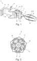
- figure 1 shows an embodiment of a clamping device 1 according to the invention, which is shown without housing 2 or has no housing 2.
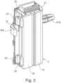
- An embodiment of the invention with housing 2 is in figure 3 shown.
- the clamping device 1 has a spindle 4 which is mounted in the axial direction and in the radial direction by means of a bearing unit 3 and can be rotated about its longitudinal axis. This is provided with a spindle thread with a defined spindle thread length. It is provided at its proximal end with an operating handle 5 or a knob or a crank, which is figure 1 is shown on the right.
- the actuating handle 5 is coupled to the spindle 4 by means of a limiting unit 6 described below.
- the spindle 4 leads on one side (in figure 1 on the right side) sealed out of the housing 2.
- the spindle 4 is in engagement with a spindle nut 7 via its spindle thread. This is also arranged inside the housing 2 .
- the spindle nut 7 is with a jaw 8 operatively connected. Alternatively, it can be part of the clamping jaw 8.
- the clamping jaw 8 projects out of the housing 2 on the side opposite the actuating handle 5 through a sealed opening.
- the end of the clamping jaw 8 remote from the spindle nut 7 is designed as an angled, here right-angled clamping profile with a bearing structure 9 .
- a bead 10 is introduced into the angled arm of the clamping jaw 8, which is aligned perpendicularly to the longitudinal axis of the spindle 4. In an alternative embodiment, several beads 10 can be introduced.
- the bearing unit 3 has two fastening straps 11 with which the housing 2 is/is fastened to the bearing unit 3 . It also has a central opening 12 through which the proximal end of the clamping jaw 8 and the spindle 4 pass.
- the proximal end of the clamping jaw 8 has two proximal parallel clamping jaw arms 13, 14, between which a free space is formed, in which the spindle 4 engages.
- the distal end of the spindle 4 engages in an elastic stop element 15 .
- the stop element 15 is designed and positioned in such a way that the spindle nut 7 comes into contact with the stop element 15 when opening the clamping device 1 in the maximum end position, ie in the maximum unscrewed state, and deforms it elastically. As a result of its elastic restoring force during such a deformation, the stop element 15 exerts a restoring force on the spindle nut 7, which forces it back in the direction of the spindle.
- Its spindle thread is open on the side of the spindle 4 facing the stop element 15 and is formed with a free-wheeling area, not shown in the figures. The length of the freewheeling area in the axial direction of the spindle corresponds approximately to the length of the spindle nut 7 in the axial direction.
- the spindle nut 7 and the spindle thread are not in mutual engagement when the spindle nut has fully run into the freewheel when the clamping device 1 is opened.
- the stop element 15 is deformed by the spindle nut 7 lying against it in such a way that there is a sufficiently high restoring force on it exerts urging the spindle nut 7 back towards the spindle 4 and into threaded engagement with the spindle threads.
- such a threaded freewheel and such a stop element can be formed not only on the distal side of the spindle, as in the exemplary embodiment shown, but alternatively on its proximal side or on both sides, distally and proximally.
- the limitation unit 6 is, as well in figure 2 can be seen, arranged inside the actuating handle 5 having a handle housing 16 . It has a plurality of laminations 17 connected to the spindle 4 in a rotationally fixed manner. These contact the radially inner side of the handle housing 16 with their respective radially outer end. A plurality of latching contours 18 are formed in this, here in the form of grooves extending in the axial direction, between which there is a respective elevation. The lamellae 17 together with the latching contours 18 form a slipping clutch which acts as a limiting unit 6 .
- a torque exerted by a user when clamping or loosening the clamping device by a rotary actuation on the actuating handle 5 is transmitted via the latching contours 18 to the lamellae 17 and from these to the spindle 4 .
- the slats 17 now have an elasticity that is matched to a limit torque. If this limit value is exceeded, the slats 17 deform in such a way that they come loose from the grooves of the latching contour 18 and slide on it.
- the limiting unit 6 only slips in one direction of rotation, namely counterclockwise. According to the invention, slipping can take place alternatively in the other direction of rotation, ie in the clockwise direction. It is also within the scope of the invention that the limiting unit 6 can slip in both directions of rotation after the respective limit values have been exceeded.
- FIG 3 shows the clamping device 1 with the housing 2, which is secured by means of the in figure 1 recognizable fastening tabs 11 is arranged on the bearing unit 3.
- the housing 2 comprises two housing halves 19, 20 (these can also be combined to form one part, preferably in one piece of material) and is closed on the front side with a cover 21 in each case.
- two contact sections 22 are formed, which are each provided with a bead 23 distally.
- the contact sections 22 and the contact structure 9 are designed to be resistant to chemicals. In this way, when the clamping jaw 8 is tightened, slipping or twisting of a medical device arranged on the guide by means of the clamping device 1 can be permanently avoided. In particular, they are designed to be interchangeable so that they can be replaced in the event of aging, wear and tear or destruction. As a result of the geometry shown in the figures, different guide geometries and diameters can be clamped. Particularly advantageous is the in figure 3 shown arrangement of the system sections 22 and the system structure 9, which allows a jam-free clamping of a medical device.
Landscapes
- Health & Medical Sciences (AREA)
- Engineering & Computer Science (AREA)
- General Engineering & Computer Science (AREA)
- Hematology (AREA)
- Biomedical Technology (AREA)
- Heart & Thoracic Surgery (AREA)
- Anesthesiology (AREA)
- Life Sciences & Earth Sciences (AREA)
- Animal Behavior & Ethology (AREA)
- General Health & Medical Sciences (AREA)
- Public Health (AREA)
- Veterinary Medicine (AREA)
- Vascular Medicine (AREA)
- Mechanical Engineering (AREA)
- Clamps And Clips (AREA)
Applications Claiming Priority (2)
| Application Number | Priority Date | Filing Date | Title |
|---|---|---|---|
| DE102016113355.8A DE102016113355A1 (de) | 2016-07-20 | 2016-07-20 | Medizintechnische Klemmvorrichtung mit Rutschkupplung |
| PCT/EP2017/068220 WO2018015427A1 (de) | 2016-07-20 | 2017-07-19 | Medizintechnische klemmvorrichtung mit rutschkupplung |
Publications (2)
| Publication Number | Publication Date |
|---|---|
| EP3487557A1 EP3487557A1 (de) | 2019-05-29 |
| EP3487557B1 true EP3487557B1 (de) | 2023-05-03 |
Family
ID=59626558
Family Applications (1)
| Application Number | Title | Priority Date | Filing Date |
|---|---|---|---|
| EP17752014.5A Active EP3487557B1 (de) | 2016-07-20 | 2017-07-19 | Medizintechnische klemmvorrichtung mit sicherheitskupplung |
Country Status (4)
| Country | Link |
|---|---|
| EP (1) | EP3487557B1 (pl) |
| DE (1) | DE102016113355A1 (pl) |
| PL (1) | PL3487557T3 (pl) |
| WO (1) | WO2018015427A1 (pl) |
Families Citing this family (1)
| Publication number | Priority date | Publication date | Assignee | Title |
|---|---|---|---|---|
| CN114377249B (zh) * | 2021-12-24 | 2024-05-14 | 中国人民解放军联勤保障部队第九二〇医院 | 一种智能化儿科护理用静脉输液管理装置 |
Family Cites Families (13)
| Publication number | Priority date | Publication date | Assignee | Title |
|---|---|---|---|---|
| US4832299A (en) * | 1987-12-04 | 1989-05-23 | Pacesetter Infusion, Ltd. | Clamp fixture |
| DE10341697B3 (de) * | 2003-09-10 | 2004-10-07 | Felo-Werkzeugfabrik Holland-Letz Gmbh | Schraubwerkzeug mit einer Vorrichtung zur Begrenzung des übertragenen Drehmomentes |
| US7896572B2 (en) * | 2003-10-30 | 2011-03-01 | Hospira, Inc. | Medical device system |
| US8459602B2 (en) * | 2006-05-19 | 2013-06-11 | Arnold Herskovic | Clamping device |
| WO2008139951A1 (ja) * | 2007-05-08 | 2008-11-20 | Terumo Kabushiki Kaisha | クランプ装置 |
| EP2642931B1 (en) * | 2010-11-22 | 2017-03-15 | Dfine, Inc. | System for use in treatment of vertebral fractures |
| TWI396608B (zh) * | 2011-06-03 | 2013-05-21 | Kabo Tool Co | 電子式扭力螺絲起子 |
| JP2013257004A (ja) * | 2012-06-13 | 2013-12-26 | Kohara Gear Seisakusho:Kk | クランプ装置 |
| WO2014035496A1 (en) * | 2012-08-30 | 2014-03-06 | Eca Medical Instruments | Base for disposable selectable torque limiting device |
| DE102013002009A1 (de) * | 2013-02-06 | 2014-08-07 | Abb Ag | Installationsschaltgerät mit Anschlussklemme und Klemmenabdeckteil |
| WO2014159027A1 (en) * | 2013-03-14 | 2014-10-02 | DePuy Synthes Products, LLC | Surgical torque limiting instrument |
| JP5792353B1 (ja) * | 2014-06-10 | 2015-10-07 | 株式会社トライテック | クランプ装置 |
| EP3182912B1 (en) * | 2014-08-20 | 2019-05-01 | Tecres S.P.A. | Handle to apply a torque and delivery unit provided with such handle |
-
2016
- 2016-07-20 DE DE102016113355.8A patent/DE102016113355A1/de not_active Withdrawn
-
2017
- 2017-07-19 PL PL17752014.5T patent/PL3487557T3/pl unknown
- 2017-07-19 WO PCT/EP2017/068220 patent/WO2018015427A1/de not_active Ceased
- 2017-07-19 EP EP17752014.5A patent/EP3487557B1/de active Active
Also Published As
| Publication number | Publication date |
|---|---|
| PL3487557T3 (pl) | 2023-11-27 |
| WO2018015427A1 (de) | 2018-01-25 |
| DE102016113355A1 (de) | 2018-01-25 |
| EP3487557A1 (de) | 2019-05-29 |
Similar Documents
| Publication | Publication Date | Title |
|---|---|---|
| EP2699815B1 (de) | Elektromotorischer linearantrieb | |
| DE3346248C2 (de) | Spanneinrichtung zum Einspannen von Werkzeugen | |
| EP2846951B1 (de) | Schnellspann-kupplung | |
| WO2008049141A1 (de) | Antriebsvorrichtung für bewegliche möbelteile | |
| EP2775884B1 (de) | Elektromotorischer linearantrieb, insbesondere zum verstellen von liege- und sitzmöbeln | |
| EP0860148A2 (de) | Bajonettkupplung zum lösbaren Verbinden zweier Rohrschaftinstrumente oder -instrumententeile | |
| EP0537452A1 (de) | Medizinische Zange | |
| DE102005016364B3 (de) | Vorrichtung zum Fixieren einer Elektrode im Schrittmacherbett | |
| DE202012001348U1 (de) | Zerlegbares chirurgisches Schiebeschaftinstrument | |
| EP2891826B1 (de) | Elektromotorischer Linearantrieb | |
| DE202015106773U1 (de) | Auswerferanordnung für ein bewegbares Möbelteil | |
| EP1086658B1 (de) | Zahnärztliches oder chirurgisches Winkelstück | |
| DE102004032523B4 (de) | Medizinisches Instrument | |
| EP2574376B1 (de) | Hantelsystem mit Hantelgewichten und einem Griff | |
| DE102007016529A1 (de) | Axial verstellbare Stellstange mit Schraubengewinde und verdrehbarem Mutterstück | |
| WO2018015427A1 (de) | Medizintechnische klemmvorrichtung mit rutschkupplung | |
| DE102012220651A1 (de) | Endoskop-Zwischenstück | |
| DE102013103035A1 (de) | Auflösewalze mit Drehverschluss und Sicherungselement | |
| WO2023179813A1 (de) | Abseilgerät mit drehmomentbegrenzer | |
| DE102014007123A1 (de) | Verbindungsteil zur Befestigung eines rohr- oder stabförmigen Elements an einem anderen Bauteil | |
| DE102021132076B4 (de) | Spannvorrichtung | |
| EP2979674B1 (de) | Entbindungsbett mit haltebügel und bremsvorrichtung | |
| DE102010037728B4 (de) | Linearer Aktuator und Sicherheitsmechanismus desselben | |
| DE102011002162B4 (de) | Elektromotorischer Möbelantrieb | |
| DE10131043A1 (de) | Drehfeste Verbindung mit versetzter Verzahnung |
Legal Events
| Date | Code | Title | Description |
|---|---|---|---|
| STAA | Information on the status of an ep patent application or granted ep patent |
Free format text: STATUS: UNKNOWN |
|
| STAA | Information on the status of an ep patent application or granted ep patent |
Free format text: STATUS: THE INTERNATIONAL PUBLICATION HAS BEEN MADE |
|
| PUAI | Public reference made under article 153(3) epc to a published international application that has entered the european phase |
Free format text: ORIGINAL CODE: 0009012 |
|
| STAA | Information on the status of an ep patent application or granted ep patent |
Free format text: STATUS: REQUEST FOR EXAMINATION WAS MADE |
|
| 17P | Request for examination filed |
Effective date: 20190218 |
|
| AK | Designated contracting states |
Kind code of ref document: A1 Designated state(s): AL AT BE BG CH CY CZ DE DK EE ES FI FR GB GR HR HU IE IS IT LI LT LU LV MC MK MT NL NO PL PT RO RS SE SI SK SM TR |
|
| AX | Request for extension of the european patent |
Extension state: BA ME |
|
| DAV | Request for validation of the european patent (deleted) | ||
| DAX | Request for extension of the european patent (deleted) | ||
| RIC1 | Information provided on ipc code assigned before grant |
Ipc: F16D 7/02 20060101ALI20220908BHEP Ipc: F16H 25/20 20060101ALI20220908BHEP Ipc: A61M 5/14 20060101AFI20220908BHEP |
|
| GRAP | Despatch of communication of intention to grant a patent |
Free format text: ORIGINAL CODE: EPIDOSNIGR1 |
|
| STAA | Information on the status of an ep patent application or granted ep patent |
Free format text: STATUS: GRANT OF PATENT IS INTENDED |
|
| INTG | Intention to grant announced |
Effective date: 20221014 |
|
| GRAS | Grant fee paid |
Free format text: ORIGINAL CODE: EPIDOSNIGR3 |
|
| GRAA | (expected) grant |
Free format text: ORIGINAL CODE: 0009210 |
|
| STAA | Information on the status of an ep patent application or granted ep patent |
Free format text: STATUS: THE PATENT HAS BEEN GRANTED |
|
| AK | Designated contracting states |
Kind code of ref document: B1 Designated state(s): AL AT BE BG CH CY CZ DE DK EE ES FI FR GB GR HR HU IE IS IT LI LT LU LV MC MK MT NL NO PL PT RO RS SE SI SK SM TR |
|
| REG | Reference to a national code |
Ref country code: GB Ref legal event code: FG4D Free format text: NOT ENGLISH |
|
| REG | Reference to a national code |
Ref country code: DE Ref legal event code: R096 Ref document number: 502017014682 Country of ref document: DE |
|
| REG | Reference to a national code |
Ref country code: AT Ref legal event code: REF Ref document number: 1564047 Country of ref document: AT Kind code of ref document: T Effective date: 20230515 Ref country code: CH Ref legal event code: EP |
|
| REG | Reference to a national code |
Ref country code: IE Ref legal event code: FG4D Free format text: LANGUAGE OF EP DOCUMENT: GERMAN |
|
| REG | Reference to a national code |
Ref country code: LT Ref legal event code: MG9D |
|
| REG | Reference to a national code |
Ref country code: NL Ref legal event code: MP Effective date: 20230503 |
|
| P01 | Opt-out of the competence of the unified patent court (upc) registered |
Effective date: 20230823 |
|
| PG25 | Lapsed in a contracting state [announced via postgrant information from national office to epo] |
Ref country code: SE Free format text: LAPSE BECAUSE OF FAILURE TO SUBMIT A TRANSLATION OF THE DESCRIPTION OR TO PAY THE FEE WITHIN THE PRESCRIBED TIME-LIMIT Effective date: 20230503 Ref country code: PT Free format text: LAPSE BECAUSE OF FAILURE TO SUBMIT A TRANSLATION OF THE DESCRIPTION OR TO PAY THE FEE WITHIN THE PRESCRIBED TIME-LIMIT Effective date: 20230904 Ref country code: NO Free format text: LAPSE BECAUSE OF FAILURE TO SUBMIT A TRANSLATION OF THE DESCRIPTION OR TO PAY THE FEE WITHIN THE PRESCRIBED TIME-LIMIT Effective date: 20230803 Ref country code: NL Free format text: LAPSE BECAUSE OF FAILURE TO SUBMIT A TRANSLATION OF THE DESCRIPTION OR TO PAY THE FEE WITHIN THE PRESCRIBED TIME-LIMIT Effective date: 20230503 Ref country code: ES Free format text: LAPSE BECAUSE OF FAILURE TO SUBMIT A TRANSLATION OF THE DESCRIPTION OR TO PAY THE FEE WITHIN THE PRESCRIBED TIME-LIMIT Effective date: 20230503 |
|
| PG25 | Lapsed in a contracting state [announced via postgrant information from national office to epo] |
Ref country code: RS Free format text: LAPSE BECAUSE OF FAILURE TO SUBMIT A TRANSLATION OF THE DESCRIPTION OR TO PAY THE FEE WITHIN THE PRESCRIBED TIME-LIMIT Effective date: 20230503 Ref country code: LV Free format text: LAPSE BECAUSE OF FAILURE TO SUBMIT A TRANSLATION OF THE DESCRIPTION OR TO PAY THE FEE WITHIN THE PRESCRIBED TIME-LIMIT Effective date: 20230503 Ref country code: LT Free format text: LAPSE BECAUSE OF FAILURE TO SUBMIT A TRANSLATION OF THE DESCRIPTION OR TO PAY THE FEE WITHIN THE PRESCRIBED TIME-LIMIT Effective date: 20230503 Ref country code: IS Free format text: LAPSE BECAUSE OF FAILURE TO SUBMIT A TRANSLATION OF THE DESCRIPTION OR TO PAY THE FEE WITHIN THE PRESCRIBED TIME-LIMIT Effective date: 20230903 Ref country code: HR Free format text: LAPSE BECAUSE OF FAILURE TO SUBMIT A TRANSLATION OF THE DESCRIPTION OR TO PAY THE FEE WITHIN THE PRESCRIBED TIME-LIMIT Effective date: 20230503 Ref country code: GR Free format text: LAPSE BECAUSE OF FAILURE TO SUBMIT A TRANSLATION OF THE DESCRIPTION OR TO PAY THE FEE WITHIN THE PRESCRIBED TIME-LIMIT Effective date: 20230804 |
|
| PG25 | Lapsed in a contracting state [announced via postgrant information from national office to epo] |
Ref country code: FI Free format text: LAPSE BECAUSE OF FAILURE TO SUBMIT A TRANSLATION OF THE DESCRIPTION OR TO PAY THE FEE WITHIN THE PRESCRIBED TIME-LIMIT Effective date: 20230503 |
|
| PG25 | Lapsed in a contracting state [announced via postgrant information from national office to epo] |
Ref country code: SK Free format text: LAPSE BECAUSE OF FAILURE TO SUBMIT A TRANSLATION OF THE DESCRIPTION OR TO PAY THE FEE WITHIN THE PRESCRIBED TIME-LIMIT Effective date: 20230503 |
|
| PG25 | Lapsed in a contracting state [announced via postgrant information from national office to epo] |
Ref country code: SM Free format text: LAPSE BECAUSE OF FAILURE TO SUBMIT A TRANSLATION OF THE DESCRIPTION OR TO PAY THE FEE WITHIN THE PRESCRIBED TIME-LIMIT Effective date: 20230503 Ref country code: SK Free format text: LAPSE BECAUSE OF FAILURE TO SUBMIT A TRANSLATION OF THE DESCRIPTION OR TO PAY THE FEE WITHIN THE PRESCRIBED TIME-LIMIT Effective date: 20230503 Ref country code: RO Free format text: LAPSE BECAUSE OF FAILURE TO SUBMIT A TRANSLATION OF THE DESCRIPTION OR TO PAY THE FEE WITHIN THE PRESCRIBED TIME-LIMIT Effective date: 20230503 Ref country code: EE Free format text: LAPSE BECAUSE OF FAILURE TO SUBMIT A TRANSLATION OF THE DESCRIPTION OR TO PAY THE FEE WITHIN THE PRESCRIBED TIME-LIMIT Effective date: 20230503 Ref country code: DK Free format text: LAPSE BECAUSE OF FAILURE TO SUBMIT A TRANSLATION OF THE DESCRIPTION OR TO PAY THE FEE WITHIN THE PRESCRIBED TIME-LIMIT Effective date: 20230503 Ref country code: CZ Free format text: LAPSE BECAUSE OF FAILURE TO SUBMIT A TRANSLATION OF THE DESCRIPTION OR TO PAY THE FEE WITHIN THE PRESCRIBED TIME-LIMIT Effective date: 20230503 |
|
| REG | Reference to a national code |
Ref country code: DE Ref legal event code: R097 Ref document number: 502017014682 Country of ref document: DE |
|
| PG25 | Lapsed in a contracting state [announced via postgrant information from national office to epo] |
Ref country code: MC Free format text: LAPSE BECAUSE OF FAILURE TO SUBMIT A TRANSLATION OF THE DESCRIPTION OR TO PAY THE FEE WITHIN THE PRESCRIBED TIME-LIMIT Effective date: 20230503 |
|
| PG25 | Lapsed in a contracting state [announced via postgrant information from national office to epo] |
Ref country code: MC Free format text: LAPSE BECAUSE OF FAILURE TO SUBMIT A TRANSLATION OF THE DESCRIPTION OR TO PAY THE FEE WITHIN THE PRESCRIBED TIME-LIMIT Effective date: 20230503 |
|
| PLBE | No opposition filed within time limit |
Free format text: ORIGINAL CODE: 0009261 |
|
| STAA | Information on the status of an ep patent application or granted ep patent |
Free format text: STATUS: NO OPPOSITION FILED WITHIN TIME LIMIT |
|
| REG | Reference to a national code |
Ref country code: BE Ref legal event code: MM Effective date: 20230731 |
|
| PG25 | Lapsed in a contracting state [announced via postgrant information from national office to epo] |
Ref country code: LU Free format text: LAPSE BECAUSE OF NON-PAYMENT OF DUE FEES Effective date: 20230719 |
|
| PG25 | Lapsed in a contracting state [announced via postgrant information from national office to epo] |
Ref country code: LU Free format text: LAPSE BECAUSE OF NON-PAYMENT OF DUE FEES Effective date: 20230719 |
|
| 26N | No opposition filed |
Effective date: 20240206 |
|
| REG | Reference to a national code |
Ref country code: IE Ref legal event code: MM4A |
|
| PG25 | Lapsed in a contracting state [announced via postgrant information from national office to epo] |
Ref country code: SI Free format text: LAPSE BECAUSE OF FAILURE TO SUBMIT A TRANSLATION OF THE DESCRIPTION OR TO PAY THE FEE WITHIN THE PRESCRIBED TIME-LIMIT Effective date: 20230503 |
|
| PG25 | Lapsed in a contracting state [announced via postgrant information from national office to epo] |
Ref country code: SI Free format text: LAPSE BECAUSE OF FAILURE TO SUBMIT A TRANSLATION OF THE DESCRIPTION OR TO PAY THE FEE WITHIN THE PRESCRIBED TIME-LIMIT Effective date: 20230503 Ref country code: IT Free format text: LAPSE BECAUSE OF FAILURE TO SUBMIT A TRANSLATION OF THE DESCRIPTION OR TO PAY THE FEE WITHIN THE PRESCRIBED TIME-LIMIT Effective date: 20230503 Ref country code: BE Free format text: LAPSE BECAUSE OF NON-PAYMENT OF DUE FEES Effective date: 20230731 |
|
| PG25 | Lapsed in a contracting state [announced via postgrant information from national office to epo] |
Ref country code: IE Free format text: LAPSE BECAUSE OF NON-PAYMENT OF DUE FEES Effective date: 20230719 |
|
| PG25 | Lapsed in a contracting state [announced via postgrant information from national office to epo] |
Ref country code: IE Free format text: LAPSE BECAUSE OF NON-PAYMENT OF DUE FEES Effective date: 20230719 |
|
| REG | Reference to a national code |
Ref country code: AT Ref legal event code: MM01 Ref document number: 1564047 Country of ref document: AT Kind code of ref document: T Effective date: 20230719 |
|
| PG25 | Lapsed in a contracting state [announced via postgrant information from national office to epo] |
Ref country code: AT Free format text: LAPSE BECAUSE OF NON-PAYMENT OF DUE FEES Effective date: 20230719 |
|
| PG25 | Lapsed in a contracting state [announced via postgrant information from national office to epo] |
Ref country code: AT Free format text: LAPSE BECAUSE OF NON-PAYMENT OF DUE FEES Effective date: 20230719 |
|
| PG25 | Lapsed in a contracting state [announced via postgrant information from national office to epo] |
Ref country code: BG Free format text: LAPSE BECAUSE OF FAILURE TO SUBMIT A TRANSLATION OF THE DESCRIPTION OR TO PAY THE FEE WITHIN THE PRESCRIBED TIME-LIMIT Effective date: 20230503 |
|
| PG25 | Lapsed in a contracting state [announced via postgrant information from national office to epo] |
Ref country code: BG Free format text: LAPSE BECAUSE OF FAILURE TO SUBMIT A TRANSLATION OF THE DESCRIPTION OR TO PAY THE FEE WITHIN THE PRESCRIBED TIME-LIMIT Effective date: 20230503 |
|
| PG25 | Lapsed in a contracting state [announced via postgrant information from national office to epo] |
Ref country code: CY Free format text: LAPSE BECAUSE OF FAILURE TO SUBMIT A TRANSLATION OF THE DESCRIPTION OR TO PAY THE FEE WITHIN THE PRESCRIBED TIME-LIMIT; INVALID AB INITIO Effective date: 20170719 |
|
| PG25 | Lapsed in a contracting state [announced via postgrant information from national office to epo] |
Ref country code: HU Free format text: LAPSE BECAUSE OF FAILURE TO SUBMIT A TRANSLATION OF THE DESCRIPTION OR TO PAY THE FEE WITHIN THE PRESCRIBED TIME-LIMIT; INVALID AB INITIO Effective date: 20170719 |
|
| PGFP | Annual fee paid to national office [announced via postgrant information from national office to epo] |
Ref country code: DE Payment date: 20250722 Year of fee payment: 9 |
|
| PGFP | Annual fee paid to national office [announced via postgrant information from national office to epo] |
Ref country code: PL Payment date: 20250707 Year of fee payment: 9 |
|
| PGFP | Annual fee paid to national office [announced via postgrant information from national office to epo] |
Ref country code: GB Payment date: 20250724 Year of fee payment: 9 |
|
| PGFP | Annual fee paid to national office [announced via postgrant information from national office to epo] |
Ref country code: FR Payment date: 20250723 Year of fee payment: 9 |
|
| PGFP | Annual fee paid to national office [announced via postgrant information from national office to epo] |
Ref country code: CH Payment date: 20250724 Year of fee payment: 9 |
|
| PG25 | Lapsed in a contracting state [announced via postgrant information from national office to epo] |
Ref country code: TR Free format text: LAPSE BECAUSE OF FAILURE TO SUBMIT A TRANSLATION OF THE DESCRIPTION OR TO PAY THE FEE WITHIN THE PRESCRIBED TIME-LIMIT Effective date: 20230503 |
|
| REG | Reference to a national code |
Ref country code: CH Ref legal event code: U11 Free format text: ST27 STATUS EVENT CODE: U-0-0-U10-U11 (AS PROVIDED BY THE NATIONAL OFFICE) Effective date: 20260801 |