EP3487557B1 - Medizintechnische klemmvorrichtung mit sicherheitskupplung - Google Patents
Medizintechnische klemmvorrichtung mit sicherheitskupplung Download PDFInfo
- Publication number
- EP3487557B1 EP3487557B1 EP17752014.5A EP17752014A EP3487557B1 EP 3487557 B1 EP3487557 B1 EP 3487557B1 EP 17752014 A EP17752014 A EP 17752014A EP 3487557 B1 EP3487557 B1 EP 3487557B1
- Authority
- EP
- European Patent Office
- Prior art keywords
- spindle
- clamping
- clamping device
- medical
- technical
- Prior art date
- Legal status (The legal status is an assumption and is not a legal conclusion. Google has not performed a legal analysis and makes no representation as to the accuracy of the status listed.)
- Active
Links
- 230000001419 dependent effect Effects 0.000 claims description 10
- 229910000639 Spring steel Inorganic materials 0.000 claims description 5
- 229920003023 plastic Polymers 0.000 claims description 5
- 229920001971 elastomer Polymers 0.000 claims description 4
- 229920000122 acrylonitrile butadiene styrene Polymers 0.000 claims description 3
- 229920001903 high density polyethylene Polymers 0.000 claims description 3
- 229920001684 low density polyethylene Polymers 0.000 claims description 3
- 239000007769 metal material Substances 0.000 claims description 3
- 229920006324 polyoxymethylene Polymers 0.000 claims description 3
- 239000000806 elastomer Substances 0.000 claims description 2
- 239000002184 metal Substances 0.000 claims description 2
- 239000005060 rubber Substances 0.000 claims description 2
- 229920006351 engineering plastic Polymers 0.000 claims 1
- 239000011324 bead Substances 0.000 description 9
- 230000006378 damage Effects 0.000 description 7
- 239000000463 material Substances 0.000 description 4
- 241000446313 Lamella Species 0.000 description 2
- 230000032683 aging Effects 0.000 description 2
- 230000008878 coupling Effects 0.000 description 2
- 238000010168 coupling process Methods 0.000 description 2
- 238000005859 coupling reaction Methods 0.000 description 2
- 230000000694 effects Effects 0.000 description 2
- 238000001802 infusion Methods 0.000 description 2
- 239000000126 substance Substances 0.000 description 2
- 238000011282 treatment Methods 0.000 description 2
- 230000002457 bidirectional effect Effects 0.000 description 1
- 238000004140 cleaning Methods 0.000 description 1
- 239000012459 cleaning agent Substances 0.000 description 1
- 238000010276 construction Methods 0.000 description 1
- 239000000645 desinfectant Substances 0.000 description 1
- 238000007373 indentation Methods 0.000 description 1
- 230000002427 irreversible effect Effects 0.000 description 1
- 238000003475 lamination Methods 0.000 description 1
- 239000007788 liquid Substances 0.000 description 1
- 235000016236 parenteral nutrition Nutrition 0.000 description 1
- 230000036316 preload Effects 0.000 description 1
- 230000000717 retained effect Effects 0.000 description 1
- 210000002023 somite Anatomy 0.000 description 1
- 230000003068 static effect Effects 0.000 description 1
- 238000002560 therapeutic procedure Methods 0.000 description 1
Images
Classifications
-
- A—HUMAN NECESSITIES
- A61—MEDICAL OR VETERINARY SCIENCE; HYGIENE
- A61M—DEVICES FOR INTRODUCING MEDIA INTO, OR ONTO, THE BODY; DEVICES FOR TRANSDUCING BODY MEDIA OR FOR TAKING MEDIA FROM THE BODY; DEVICES FOR PRODUCING OR ENDING SLEEP OR STUPOR
- A61M5/00—Devices for bringing media into the body in a subcutaneous, intra-vascular or intramuscular way; Accessories therefor, e.g. filling or cleaning devices, arm-rests
- A61M5/14—Infusion devices, e.g. infusing by gravity; Blood infusion; Accessories therefor
- A61M5/1414—Hanging-up devices
- A61M5/1415—Stands, brackets or the like for supporting infusion accessories
-
- F—MECHANICAL ENGINEERING; LIGHTING; HEATING; WEAPONS; BLASTING
- F16—ENGINEERING ELEMENTS AND UNITS; GENERAL MEASURES FOR PRODUCING AND MAINTAINING EFFECTIVE FUNCTIONING OF MACHINES OR INSTALLATIONS; THERMAL INSULATION IN GENERAL
- F16D—COUPLINGS FOR TRANSMITTING ROTATION; CLUTCHES; BRAKES
- F16D7/00—Slip couplings, e.g. slipping on overload, for absorbing shock
- F16D7/02—Slip couplings, e.g. slipping on overload, for absorbing shock of the friction type
- F16D7/024—Slip couplings, e.g. slipping on overload, for absorbing shock of the friction type with axially applied torque limiting friction surfaces
- F16D7/025—Slip couplings, e.g. slipping on overload, for absorbing shock of the friction type with axially applied torque limiting friction surfaces with flat clutching surfaces, e.g. discs
Definitions
- the present invention relates to a medical-technical clamping device for clamping a medical-technical device to a guide, in particular to a rod-like guide, the clamping device having two clamping sections, in particular clamping jaws, which can be moved relative to one another by means of an actuating mechanism, for clamping engagement with the guide.
- medical devices for carrying out treatments on the patient are releasably fastened directly or indirectly to guides or holding devices via holding systems.
- Such devices are, in particular, devices for infusion therapy which are releasably attached to poles such as an IV pole.
- Another possibility is a detachable attachment to guides or holding devices that are provided on hospital beds or operating tables.
- Guides fastening rods or holding devices
- a medical clamping device should be individually adaptable to such different circumstances and enable the device to be securely and easily attached.
- a problem that can arise in this case can be that the surface of the guides is usually smooth, for example chrome-plated, which entails the risk of a certain tendency for the clamping device to slide over it.
- This problem can be exacerbated by the fact that such guides are regularly cleaned and disinfected with different cleaning and disinfecting agents, which can lead to surface properties changing in such a way that the tendency of the clamping device to slide against them increases.
- be handled in the immediate vicinity of the guide or the clamping device fatty liquids that on the guide surface or between the guide and can reach the clamping device, which can also lead to significant changes in the sliding tendency.
- Known attachment systems are based on a clamping device attached to a medical device.
- the device can be clamped to a guide by means of one or two clamping jaws.
- the clamping jaws are often movable via a spindle mechanism and can be actuated for clamping on the guide. It can happen that a medical device fastened by means of such a fastening system is not sufficiently fixed and as a result can slide off or be twisted around the guides. This can be due, for example, to the fact that the guide or the clamping jaws is/are dirty, as described above.
- users usually try to exert a higher normal force on the clamping rail by increasing the clamping force in order to generate sufficient static friction.
- this can have the disadvantage that the clamping jaws, the guide or even the entire clamping device are irreversibly destroyed. In the worst case, the medical device can even fall, leading to unacceptable risks depending on the application.
- a further problem with known medical-technical clamping devices can arise if the user unscrews the spindle too much when releasing the clamping device. If this is loosened/unscrewed up to the outer stop or even beyond, depending on the version, this can lead to the spindle jamming in its associated thread in this open position and being difficult to release from this jamming. In the worst case, the spindle can be completely unsolvable. This can in turn result in irreversible destruction of individual components of the clamping device or of the medical device to be clamped.
- clamping devices can be that the clamp is not mounted in the desired position on the rod, but is imperceptibly fixed incorrectly. This can lead to skewed positioning, slipping, turning away or destruction of the clamp and/or the guide. Over and beyond In the case of a guide with a circular cross section, it can happen that the clamp fixes with its highest point on the outer diameter of the guide instead of with a bead or trough provided for this purpose. In such a case, the medical device is temporarily fixed, but not in a stable state. Proper manipulation of the seemingly clamped medical device, for example when inserting a syringe into an infusion device, may well result in the clamping device slipping off the guide.
- a clamping device for fastening a medical device for example on a rod of a stand
- a torque limiter integrated into a rotary handle, in which lamellar plates are pressed against one another by a spring and are engaged with one another.
- the object of the present invention is to provide a medical-technical clamping device that does not have the aforementioned disadvantages of known clamping devices.
- the clamping device should be user-friendly and easy to use, with excessive clamping forces to achieve a secure hold of a medical device to be fastened and clamping of the clamping device in the released state being ruled out.
- a medical-technical clamping device which has a limiting unit which is force-dependent, in particular clamping force-dependent when clamping the clamping device, and/or path-dependent, in particular path-dependent when loosening the clamping device, at least one clamping section, in particular a clamping jaw , decoupled from the operating mechanism.
- the guide can in particular be designed in the manner of a rod.
- the actuating unit has a spindle that interacts with a spindle nut.
- the spindle is preferably axially fixed, but rotatable about its longitudinal axis in the spindle Stored clamping device.
- the spindle nut is preferably axially displaceable in the direction of the spindle axis, but non-rotatably mounted in the clamping device.
- the spindle can also be axially displaceable and mechanically non-rotatably connected to the clamping jaw, and the spindle nut can be axially fixed but rotatable via an axis of rotation and mechanically connected to a rotary handle.
- the clamping device also has a housing, wherein at least one outer side of the housing forms or has a clamping jaw that interacts with a clamping jaw that can be positioned by the rotary handle, and the clamping jaws each have a bearing structure for interacting with the guide.
- the decoupling takes place in such a way that continued actuation of the clamping device after a defined limit value which triggers the decoupling is not possible, but a state reached shortly before the decoupling is retained.
- the design of the clamping device according to the invention advantageously has the effect that when the clamping device is tightened/tightened, i.e. when the clamping jaws are closed to clamp it on the guide, and/or when the clamping device is released when a certain limit value is reached, the actuating mechanism at least one of the clamping jaws is decoupled, that continued actuation beyond the limit value is not possible or has no effect, but a clamping or relative positioning of the clamping jaws that essentially corresponds to the limit value is maintained.
- the limit value and thus the decoupling of the clamping jaw from the actuating unit can be determined and effected as a function of force and/or as a function of path.
- "Force-dependent" within the meaning of the invention includes the meanings of "actuating force-dependent” as well as “clamping force-dependent”.
- the arrangement of the spindle and the spindle nut enables a space-saving design.
- An embodiment of the invention is characterized in that the limiting unit is designed in the form of a slipping clutch. This can unidirectional, i.e. only slip in one direction (release or clamp) when the limit value is exceeded, or bidirectional, i.e. slide in both directions (release and clamp) when the limit value is exceeded.
- the clamping device preferably has a rotary operating handle in which the limiting unit is integrated.
- a rotary operating handle can be assembled from two or more individual parts which form a handle housing.
- the limiting unit can be arranged therein in a torque-limiting manner. It can be implemented mechanically via a coupling element acting between the handle housing and the actuating device.
- the housing of the actuating handle can be made of a metallic material, in particular spring steel, and/or a plastic, in particular PP, PE-HD, PE-LD, POM, ABS or a similar technical plastic or combinations thereof.
- a further embodiment of the invention is characterized in that the spindle is operatively connected to the rotary handle and can be driven.
- this operative connection can advantageously be formed via the limiting unit.
- This can be equipped in particular with one or more radially positioned elastic lamellae, which on the one hand are connected to the spindle in a torsion-proof manner and on the other hand engage in a latching contour formed in the handle.
- this lamella construction can also be modified as long as the rotary movement of the turning handle is transmitted to the spindle via a frictional or elastic form fit, with the frictional fit or the form fit determining the maximum torque that can be transmitted.
- the lamellae can also be aligned axially instead of being radially aligned and for this purpose are arranged, for example, on a free axial end face of the rotary handle or the spindle and engage in a correspondingly axially arranged latching contour on the opposite component.
- the slats it is also not absolutely necessary to design the slats to be spring-elastic. Rather, the slats could also be rigid and instead their storage could be spring-elastic.
- the spindle has a spindle thread that is open on one side.
- this can be open in the closing direction and/or in the opening direction of the spindle.
- the active spindle thread length over which an adjustment of the clamping device can be effected is limited. If the spindle nut moves beyond the end of the spindle thread as a result of excessive adjustment, the spindle nut and the spindle become disengaged and force can no longer be transmitted to the clamping jaw by continuously turning the spindle.
- An overload protection is designed in such a way that mechanical destruction of the clamping device and the guide is reliably avoided.
- the spindle thread is open in the spindle opening direction (opposite to the spindle clamping direction). This creates an overload protection which acts when the clamping jaws are opened, particularly in a case in which the clamping jaw has been fully opened (the spindle nut is then in abutment at the end of the thread) and a user nevertheless continues with an adjustment. Since the spindle and spindle nut are then out of thread engagement, the spindle rotates more or less idle relative to the spindle nut, so that the spindle nut and spindle cannot jam.
- a particularly elastic stop element is arranged at the end of the spindle such that the spindle nut or the spindle come into contact with the stop element as soon as the spindle nut and the spindle are disengaged from the open end of the spindle thread.
- the stop element can be arranged or formed in a particularly advantageous manner between the spindle thread end and a housing of a medical device to be fastened. It is preferably positioned such that the spindle nut abuts it after, and particularly immediately after, disengagement from the spindle threads. As a result of the elasticity of the stop element, the spindle nut is pressed back in the direction of the spindle thread after leaving the spindle thread.
- the stop element consists of an elastomer, rubber or metal, in particular of spring steel, and/or is designed in the form of a ring, a spiral spring or a leaf spring.
- a further embodiment of the invention is characterized in that the limiting unit has one or more radially positioned elastic lamellae, which is or are non-rotatably connected to the spindle and engages with its radially outer end in a locking contour formed in the rotary handle.
- the lamellae can be arranged in a rotationally fixed manner on the rotary handle, in particular on a housing of the rotary handle, and can engage in latching contours formed on the spindle.
- the slats are preferably designed in such a way that they can deviate or slide off in a first direction on the latching contour when a limit torque is exceeded during a relative movement between the spindle and the rotary handle.
- the latching contour is preferably formed by grooves/depressions and/or projections formed in the radial direction.
- the limit value which when exceeded causes the limiting unit to slip, is defined by certain properties.
- certain properties in this context, particular mention should be made of the strength (rigidity) of the material of the coupling element and/or the number of lamellae and/or the depth of the locking contour and/or the outer diameter of the lamellae and/or the wall thickness of the lamellae and/or the width of the slats.
- the aforementioned properties determine the tendency of the slats to deviate when they come into contact with the latching contour.
- the disks of the slipping clutch can be made of a metallic material, in particular spring steel, and/or a plastic, in particular PP, PE-HD, PE-LD, POM, ABS or a similar technical plastic or a combination thereof.
- the distances between the inwardly directed slats are preferably formed in such a way that a user hears a clicking noise or a series of clicking noises when the limiting unit slips through. In this way, the applicant is informed acoustically or haptically that he/she actuates the handle beyond the torque limit, for example by half a turn.
- the geometry and the surface quality of the slats and/or the latching contour can be designed in such a way that the slats slide off gently when they are over-tightened.
- the sliding surfaces of the lamellae and the latching contour are not or only slightly stressed in order to achieve a permanently constant torque limitation.
- the clamping jaws can each have an abutment structure for interacting with a guide.
- the abutment structure forms a support with which the clamping jaw contacts the guide. It is preferably designed with special material properties and can in particular consist of a combination of a hard component with a soft component with a defined coefficient of friction and a defined hardness in order to permanently prevent the medical device from slipping or twisting off or on the guide when the clamping jaw is tightened.
- the contact structure can in particular be resistant to chemicals in order to be able to permanently prevent the medical device from slipping off or twisting on the rod when the clamping jaw is tightened. In particular, it can be designed to be exchangeable, so that in the event of aging, wear and tear or destruction, replacement is possible without any problems.
- a particularly secure attachment can be achieved if at least one of the clamping jaws, preferably both or all of the clamping jaws, is/are designed with a depression or bead.
- This indentation or bead is preferably matched to the shape of the guide and ensures that, e.g. in the case of a guide with a circular cross-section, different cross-sectional diameters are centered in one direction in such a way that the medical device is always fixed parallel to the guide and is not mounted at an angle and the The introduction of force always leads through the (middle) axis of the guide.
- the geometry of the contact structure is suitable, it can be ensured that secure attachment to the guide is possible even when the soft component is removed.
- the abutment structure can be designed in such a way that a tightness of the housing, for example IPX4, is ensured even when the soft component is removed.
- the invention limits the torque exerted by the clamping device on the guide by means of a slipping clutch integrated into an operating handle.
- the torque exerted to release the clamping device can be limited by means of the slipping clutch.
- the spindle can be prevented from getting stuck.
- a support for the clamping jaws which is matched to the guide interacting with the clamping jaws in terms of shape, hardness and material, can be used to avoid incorrect assembly and/or slipping within the scope of the invention.
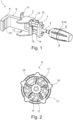
- figure 1 shows an embodiment of a clamping device 1 according to the invention, which is shown without housing 2 or has no housing 2.
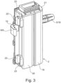
- An embodiment of the invention with housing 2 is in figure 3 shown.
- the clamping device 1 has a spindle 4 which is mounted in the axial direction and in the radial direction by means of a bearing unit 3 and can be rotated about its longitudinal axis. This is provided with a spindle thread with a defined spindle thread length. It is provided at its proximal end with an operating handle 5 or a knob or a crank, which is figure 1 is shown on the right.
- the actuating handle 5 is coupled to the spindle 4 by means of a limiting unit 6 described below.
- the spindle 4 leads on one side (in figure 1 on the right side) sealed out of the housing 2.
- the spindle 4 is in engagement with a spindle nut 7 via its spindle thread. This is also arranged inside the housing 2 .
- the spindle nut 7 is with a jaw 8 operatively connected. Alternatively, it can be part of the clamping jaw 8.
- the clamping jaw 8 projects out of the housing 2 on the side opposite the actuating handle 5 through a sealed opening.
- the end of the clamping jaw 8 remote from the spindle nut 7 is designed as an angled, here right-angled clamping profile with a bearing structure 9 .
- a bead 10 is introduced into the angled arm of the clamping jaw 8, which is aligned perpendicularly to the longitudinal axis of the spindle 4. In an alternative embodiment, several beads 10 can be introduced.
- the bearing unit 3 has two fastening straps 11 with which the housing 2 is/is fastened to the bearing unit 3 . It also has a central opening 12 through which the proximal end of the clamping jaw 8 and the spindle 4 pass.
- the proximal end of the clamping jaw 8 has two proximal parallel clamping jaw arms 13, 14, between which a free space is formed, in which the spindle 4 engages.
- the distal end of the spindle 4 engages in an elastic stop element 15 .
- the stop element 15 is designed and positioned in such a way that the spindle nut 7 comes into contact with the stop element 15 when opening the clamping device 1 in the maximum end position, ie in the maximum unscrewed state, and deforms it elastically. As a result of its elastic restoring force during such a deformation, the stop element 15 exerts a restoring force on the spindle nut 7, which forces it back in the direction of the spindle.
- Its spindle thread is open on the side of the spindle 4 facing the stop element 15 and is formed with a free-wheeling area, not shown in the figures. The length of the freewheeling area in the axial direction of the spindle corresponds approximately to the length of the spindle nut 7 in the axial direction.
- the spindle nut 7 and the spindle thread are not in mutual engagement when the spindle nut has fully run into the freewheel when the clamping device 1 is opened.
- the stop element 15 is deformed by the spindle nut 7 lying against it in such a way that there is a sufficiently high restoring force on it exerts urging the spindle nut 7 back towards the spindle 4 and into threaded engagement with the spindle threads.
- such a threaded freewheel and such a stop element can be formed not only on the distal side of the spindle, as in the exemplary embodiment shown, but alternatively on its proximal side or on both sides, distally and proximally.
- the limitation unit 6 is, as well in figure 2 can be seen, arranged inside the actuating handle 5 having a handle housing 16 . It has a plurality of laminations 17 connected to the spindle 4 in a rotationally fixed manner. These contact the radially inner side of the handle housing 16 with their respective radially outer end. A plurality of latching contours 18 are formed in this, here in the form of grooves extending in the axial direction, between which there is a respective elevation. The lamellae 17 together with the latching contours 18 form a slipping clutch which acts as a limiting unit 6 .
- a torque exerted by a user when clamping or loosening the clamping device by a rotary actuation on the actuating handle 5 is transmitted via the latching contours 18 to the lamellae 17 and from these to the spindle 4 .
- the slats 17 now have an elasticity that is matched to a limit torque. If this limit value is exceeded, the slats 17 deform in such a way that they come loose from the grooves of the latching contour 18 and slide on it.
- the limiting unit 6 only slips in one direction of rotation, namely counterclockwise. According to the invention, slipping can take place alternatively in the other direction of rotation, ie in the clockwise direction. It is also within the scope of the invention that the limiting unit 6 can slip in both directions of rotation after the respective limit values have been exceeded.
- FIG 3 shows the clamping device 1 with the housing 2, which is secured by means of the in figure 1 recognizable fastening tabs 11 is arranged on the bearing unit 3.
- the housing 2 comprises two housing halves 19, 20 (these can also be combined to form one part, preferably in one piece of material) and is closed on the front side with a cover 21 in each case.
- two contact sections 22 are formed, which are each provided with a bead 23 distally.
- the contact sections 22 and the contact structure 9 are designed to be resistant to chemicals. In this way, when the clamping jaw 8 is tightened, slipping or twisting of a medical device arranged on the guide by means of the clamping device 1 can be permanently avoided. In particular, they are designed to be interchangeable so that they can be replaced in the event of aging, wear and tear or destruction. As a result of the geometry shown in the figures, different guide geometries and diameters can be clamped. Particularly advantageous is the in figure 3 shown arrangement of the system sections 22 and the system structure 9, which allows a jam-free clamping of a medical device.
Description
- Die vorliegende Erfindung betrifft eine medizintechnische Klemmvorrichtung zur klemmenden Befestigung eines medizintechnischen Geräts an einer Führung, insbesondere an einer stangenartigen Führung, wobei die Klemmvorrichtung zwei zueinander mittels einer Betätigungsmechanik relativbewegbare Klemmabschnitte, insbesondere Klemmbacken, für einen klemmenden Eingriff mit der Führung aufweist.
- In Krankenhäusern, Kliniken oder anderen medizinischen Behandlungsstätten werden Medizingeräte zur Durchführung von Behandlungen am Patienten direkt oder indirekt über Haltesysteme an Führungen oder Halteeinrichtungen lösbar befestigt. Solche Geräte sind insbesondere Geräte für eine Infusionstherapie, die an Stangen wie z.B. einem Infusionsständer lösbar befestigt werden. Eine weitere Möglichkeit ist eine lösbare Befestigung an Führungen oder Halteeinrichtungen, die an Krankenbetten oder OP-Tischen vorgesehen sind.
- Zu diesem Zweck vorgesehene Führungen (Befestigungsstangen oder Halteeinrichtungen) sind in der Regel mit unterschiedlichen Querschnittsformen, Oberflächen und Abmessungen, insbesondere Durchmessern realisiert. Eine medizinische Klemmvorrichtung sollte an solche unterschiedliche Gegebenheiten individuell anpassbar sein und ein sicheres und einfaches Befestigen des Geräts ermöglichen. Ein dabei auftretendes Problem kann sein, dass die Oberfläche der Führungen in der Regel glatt ist, z.B. verchromt, was die Gefahr einer gewissen Gleitneigung der Klemmvorrichtung daran birgt. Dieses Problem kann dadurch verstärkt werden, dass solche Führungen regelmäßig mit unterschiedlichen Reinigungs- und Desinfektionsmitteln gereinigt und desinfiziert werden, was dazu führen kann, dass sich Oberflächeneigenschaften so verändern, dass die Gleitneigung der Klemmvorrichtung daran ansteigt. Auch können, insbesondere im Rahmen einer parenteralen Ernährung, im direkten Umfeld der Führung bzw. der Klemmvorrichtung fetthaltige Flüssigkeiten gehandhabt werden, die auf die Führungsoberfläche bzw. zwischen die Führung und die Klemmvorrichtung gelangen können, was ebenfalls zu erheblichen Veränderungen der Gleitneigung führen kann.
- Bekannte Befestigungssysteme basieren auf einer an einem Medizingerät befestigten Klemmvorrichtung. In der Regel ist das Gerät mittels einer oder zweier Klemmbacken an einer Führung festklemmbar. Die Klemmbacken sind häufig über eine Spindelmechanik beweglich und zum Klemmen an der Führung zu betätigen. Es kann passieren, dass ein mittels eines solchen Befestigungssystems befestigtes Medizingerät nicht ausreichend fixiert ist und in Folge dessen abgleiten oder sich um die Führen herum verdrehen lassen kann. Dies kann beispielsweise dadurch begründet sein, dass die Führung oder die Klemmbacken wie vorstehend beschrieben verschmutzt ist bzw. sind. In der Regel versuchen Anwender im Falle einer unzureichenden Klemmung durch Erhöhen der Klemmkraft eine höhere Normalkraft auf die Klemmschiene auszuüben, um so ausreichende Haftreibung zu erzeugen. Dies kann aber in nachteiliger Weise dazu führen, dass die Klemmbacken, die Führung oder sogar die gesamte Klemmvorrichtung irreversibel zerstört werden. Schlimmstenfalls kann das Medizingerät sogar herabfallen, was je nach Anwendungsfall zu unvertretbaren Risiken führt.
- Ein weiteres Problem bei bekannten medizintechnischen Klemmvorrichtungen kann durch zu starkes anwenderseitiges Aufdrehen der Spindel beim Lösen der Klemmvorrichtung entstehen. Wird diese bis zum äußeren Anschlag oder sogar darüber hinaus gelöst/ausgeschraubt, kann das je nach Ausführung dazu führen, dass sich die Spindel in dieser offenen Position in dem ihr zugehörigen Gewinde verklemmt und aus dieser Verklemmung nur schwer wieder lösbar ist. Schlimmstenfalls kann die Spindel gänzlich unlösbar sein. Folge kann wiederum eine irreversible Zerstörung einzelner Komponenten der Klemmvorrichtung oder des zu klemmenden medizinischen Geräts sein.
- Ein weiteres Problem bekannter Klemmvorrichtungen kann sein, dass die Klemme nicht in der erwünschten Position an der Stange montiert wird, sondern unmerklich falsch fixiert wird. Dies kann zu einem schrägen Positionieren, Abgleiten, Wegdrehen oder zu einer Zerstörung der Klemme und/oder der Führung führen. Darüber hinaus kann es im Falle einer Führung mit Kreisquerschnitt dazu kommen, dass die Klemme mit ihrem höchsten Punkt an dem Außendurchmesser der Führung fixiert, anstatt mit einer dazu vorgesehenen Sicke oder Mulde. In einem solchen Fall ist das Medizingerät zwar temporär fixiert, allerdings nicht in einem stabilen Zustand. Wohlmöglich kann es bei sachgemäßem Manipulieren am scheinbar festgeklemmten medizintechnischen Gerät, z.B. beim Einlegen einer Spritze in ein Infusionsgerät, dazu kommen, dass die Klemmvorrichtung an der Führung abrutscht.
- Beispielsweise ist aus
JP 5 792353 B1 - Vor diesem Hintergrund liegt der vorliegenden Erfindung die Aufgabe zugrunde, eine medizintechnische Klemmvorrichtung zu schaffen, die die vorgenannten Nachteile bekannter Klemmvorrichtungen nicht aufweist. Die Klemmvorrichtung soll nutzerfreundlich und einfach zu bedienen sein, wobei insbesondere zu starke Klemmkräfte zum Erzielen eines sicheren Halts eines zu befestigenden medizintechnischen Geräts sowie ein Festklemmen der Klemmvorrichtung im gelösten Zustand ausgeschlossen sind.
- Diese Aufgabe wird nach der vorliegenden Erfindung gelöst durch eine medizintechnische Klemmvorrichtung gemäß Anspruch 1, die eine Begrenzungseinheit aufweist, die kraftabhängig, insbesondere klemmkraftabhängig beim Festklemmen der Klemmvorrichtung, und/oder wegabhängig, insbesondere wegabhängig beim Lösen der Klemmvorrichtung, zumindest einen Klemmabschnitt, insbesondere eine Klemmbacke, von der Betätigungsmechanik entkoppelt. Die Führung kann insbesondere stangenartig ausgebildet sein. Ferner weist die Betätigungseinheit eine mit einer Spindelmutter zusammenwirkende Spindel auf. Die Spindel ist vorzugsweise axialfest, aber um ihre Spindellängsachse rotierbar in der Klemmvorrichtung gelagert. Die Spindelmutter ist vorzugsweise in Richtung der Spindelachse axialverschiebbar, aber drehfest in der Klemmvorrichtung gelagert. Die Spindel kann alternativ auch axial verschiebbar und mechanisch mit der Klemmbacke nicht rotierbar verbunden sein und die Spindelmutter kann axial fixiert, jedoch über eine Drehachse rotierbar und mechanisch mit einem Drehhandgriff verbunden sein. Die Klemmvorrichtung weist ferner ein Gehäuse auf, wobei zumindest eine Außenseite des Gehäuses eine mit einer durch den Drehhandgriff positionierbaren Klemmbacke zusammenwirkende Klemmbacke ausbildet oder aufweist, und die Klemmbacken jeweils eine Anlagestruktur zum Zusammenwirken mit der Führung aufweisen.
- Die Entkopplung erfolgt nach der Erfindung derart, dass eine fortgeführte Betätigung der Klemmvorrichtung nach einem Überschreiten eines definierten Grenzwerts, was die Entkopplung auslöst, nicht möglich ist, ein kurz vor der Entkopplung erreichter Zustand aber bewahrt wird. Durch die erfindungsgemäße Ausbildung der Klemmvorrichtung wird in vorteilhafter Weise bewirkt, dass bei einem Anziehen/Festziehen der Klemmvorrichtung, also bei einem Schließen der Klemmbacken zum Festklemmen an der Führung, und/oder bei einem Lösen der Klemmvorrichtung bei Erreichen eines bestimmten Grenzwerts die Betätigungsmechanik so von zumindest einer der Klemmbacken entkoppelt wird, dass fortgeführtes Betätigen über den Grenzwert hinaus nicht möglich ist oder aber ohne Wirkung ist, eine dem Grenzwert im Wesentlichen entsprechende Klemmung bzw. Relativpositionierung der Klemmbacken jedoch gehalten wird. Im Rahmen der Erfindung können der Grenzwert und damit die Entkopplung der Klemmbacke von der Betätigungseinheit kraftabhängig und/oder wegabhängig bestimmt sein und erfolgen. "Kraftabhängig" im Sinne der Erfindung beinhaltet die Bedeutungen von "betätigungskraftabhängig" wie auch von "klemmkraftabhängig". Ferner wird durch die Anordnung der Spindel und der Spindelmutter eine platzsparende Bauweise ermöglicht.
- Vorteilhafte Ausführungsformen der Erfindung sind in den Unteransprüchen beansprucht und werden nachfolgend näher erläutert.
- Eine Ausführungsform der Erfindung ist dadurch gekennzeichnet, dass die Begrenzungseinheit in Form einer Rutschkupplung ausgebildet ist. Diese kann unidirektional, also nur in eine Richtung (Lösen oder Klemmen) bei Überschreiten des Grenzwerts rutschen, oder bidirektional, also in beide Richtungen (Lösen und Klemmen) bei Überschreiten des Grenzwerts rutschen, wirken.
- Vorzugsweise weist die Klemmvorrichtung einen Drehbetätigungsgriff auf, in den die Begrenzungseinheit integriert ist. Ein solcher Drehbetätigungsgriff kann nach der Erfindung aus zwei oder mehreren Einzelteilen zusammengefügt sein, die ein Griffgehäuse ausbilden. Die Begrenzungseinheit kann darin drehmomentbegrenzend angeordnet sein. Sie kann mechanisch über ein zwischen dem Griffgehäuse und der Betätigungsvorrichtung wirkendes Kupplungselement realisiert sein. Das Gehäuse des Betätigungsgriffs kann nach der Erfindung aus einem metallischen Werkstoff, insbesondere aus Federstahl, und/oder aus einem Kunststoff, insbesondere aus PP, PE-HD, PE-LD, POM, ABS oder einem ähnlichen technischen Kunststoff oder Kombinationen davon bestehen.
- Eine weitere Ausführungsform der Erfindung ist dadurch gekennzeichnet, dass die Spindel mit dem Drehhandgriff wirkverbunden und antreibbar ist. Diese Wirkverbindung kann nach der Erfindung in vorteilhafter Weise über die Begrenzungseinheit ausgebildet sein. Diese kann insbesondere mit einer oder mehreren radial positionierten elastischen Lamellen ausgestattet sein, die einerseits verdrehsicher mit der Spindel verbunden sind und andererseits in eine in dem Griff ausgebildete Rastkontur eingreifen.
- Grundsätzlich ist diese Lamellenkonstruktion auch abwandelbar, solange die Drehbewegung des Drehhandgriffs über einen Reib- oder elastischen Formschluss auf die Spindel übertragen wird, wobei der Reibschluss oder der Formschluss das maximal übertragbare Drehmoment bestimmt. Beispielsweise können die Lamellen anstelle deren radialer Ausrichtung auch axial ausgerichtet sein und sich hierfür beispielsweise an einer freien axialen Stirnfläche des Drehhandgriffs oder der Spindel anordnen sowie in eine entsprechend axial angeordnete Rastkontur am gegenüberliegenden Bauteil eingreifen. Auch ist es nicht unbedingt erforderlich die Lamellen federelastisch auszubilden. Vielmehr könnten die Lamellen auch starr ausgeführt und stattdessen deren Lagerung federelastisch sein.
- Eine weitere Ausführungsform der Erfindung ist dadurch gekennzeichnet, dass die Spindel ein einseitig offenes Spindelgewinde aufweist. Dieses kann im Rahmen der Erfindung in Schließrichtung und/oder in Öffnungsrichtung der Spindel offen sein. Auf diese Weise ist die aktive Spindelgewindelänge, über die eine Verstellung der Klemmvorrichtung bewirkt werden kann, begrenzt. Bewegt sich die Spindelmutter auf dem Spindelgewinde infolge zu großer Verstellung über das Ende des Spindelgewindes hinaus, gelangen die Spindelmutter und die Spindel außer Eingriff und es kann durch fortwährendes Verdrehen der Spindel keine Kraft mehr auf die Klemmbacke übertragen werden. Es ist so eine Überlastsicherung ausgebildet, die eine mechanische Zerstörung der Klemmvorrichtung und der Führung sicher vermeidet. Bei einer Ausführungsform ist das Spindelgewinde in die Öffnungsrichtung der Spindel (gegenüber der Klemmrichtung der Spindel) offen. Dadurch wird eine Überlastsicherung geschaffen, die beim Öffnen der Klemmbacken wirkt, insbesondere in einem Fall, in dem die Klemmbacke vollständig geöffnet wurde (die Spindelmutter liegt dann am Gewindeende in Anschlag) und ein Anwender dennoch mit einer Verstellung fortfährt. Da Spindel und Spindelmutter dann außer Gewindeeingriff sind, dreht die Spindel gegenüber der Spindelmutter quasi leer, so dass sich Spindelmutter und Spindel nicht verklemmen können.
- Es ist besonders vorteilhaft, wenn endseitig der Spindel ein insbesondere elastisches Anschlagelement angeordnet ist, derart, dass die Spindelmutter oder die Spindel an dem Anschlagelement zur Anlage kommen, sobald die Spindelmutter und die Spindel am offenen Spindelgewindeende außer Eingriff gelangt sind. Das Anschlagelement kann nach der Erfindung in besonders vorteilhafter Weise zwischen dem Spindelgewindeende und einem Gehäuse eines zu befestigenden Medizingeräts angeordnet oder ausgebildet sein. Es ist vorzugsweise derart positioniert, dass die Spindelmutter daran nach, und insbesondere unmittelbar nach, einem Außer-Eingriff-Gelangen vom Spindelgewinde zur Anlage kommt. Infolge der Elastizität des Anschlagelements wird die Spindelmutter nach dem Verlassen des Spindelgewindes zurück in Richtung des Spindelgewindes gedrückt. Solange die Drehrichtung der Spindel beibehalten wird, rutschen Spindelmutter und Spindel gegenseitig durch. Sobald aber die Drehrichtung der Spindel umgekehrt wird, wird die Spindelmutter infolge der durch das elastische Element auf sie ausgeübten Vorspannung in Richtung der Spindel automatisch zurück in Eingriff mit dem Spindelgewinde gebracht. Es ist auf diese Weise sichergestellt, dass die Klemmbacke auch bei einem vollständigen Herausdrehen (außer Eingriff gelangen) oder Lösen von Spindel und Spindelmutter stets wieder ohne Probleme in Klemmrichtung angezogen werden kann.
- Nach einer Ausführungsform der Erfindung ist vorgesehen, dass das Anschlagelement aus einem Elastomer, Gummi oder Metall, insbesondere aus einem Federstahl besteht und/oder in Form eines Rings, einer Spiralfeder oder einer Blattfeder ausgebildet ist.
- Eine weitere Ausführungsform der Erfindung ist dadurch gekennzeichnet, dass die Begrenzungseinheit eine oder mehrere radial positionierte elastische Lamellen aufweist, die drehfest mit der Spindel verbunden ist bzw. sind und mit ihrem jeweils radial äußeren Ende in eine in dem Drehhandgriff ausgebildete Rastkontur eingreift. Alternativ können die Lamellen am Drehhandgriff, insbesondere an einem Gehäuse des Drehhandgriffs, drehfest angeordnet sein und in an der Spindel ausgebildete Rastkonturen eingreifen. Die Lamellen sind vorzugsweise so gestaltet, dass sie bei Überschreiten einer Grenzdrehkraft bei einer Relativbewegung zwischen der Spindel und dem Drehhandgriff in eine erste Richtung an der Rastkontur ausweichen oder abgleiten können. Bei einer Relativbewegung in die entgegengesetzte Richtung bewirken sie ein Sperren durch einen Eingriff mit der Rastkontur. Auf diese Weise kann zum Öffnen der Klemmbacke ein größeres Moment übertragen werden als zum Schließen. Die Rastkontur ist vorzugsweise durch in radialer Richtung ausgebildete Nuten/Vertiefungen und/oder Vorsprünge ausgebildet.
- Der Grenzwert, bei dessen Überschreiten es zu einem Durchrutschen der Begrenzungseinheit kommt, ist durch bestimmte Eigenschaften definiert. Zu nennen sind in diesem Zusammenhang insbesondere die Festigkeit (Steifigkeit) des Materials des Kupplungselements und/oder die Anzahl der Lamellen und/oder die Tiefe der Rastkontur und/oder der Außendurchmesser der Lamellen und/oder die Wandstärke der Lamellen und/oder die Breite der Lamellen. Die vorgenannten Eigenschaften bestimmen die Neigung der Lamellen, bei Kontakt mit der Rastkontur dieser auszuweichen. Durch geeignete Auswahl solcher Eigenschaften kann eine entsprechende nominale Drehmomentbegrenzung erzielt werden, infolge deren eine entsprechende Normalkraft über die Spindel und die Spindelmutter auf die Klemmbacke übertragen wird und somit eine entsprechende Haltekraft des Gesamtbefestigung erzielt wird.
- Die Lamellen der Rutschkupplung können aus einem metallischen Werkstoff, insbesondere aus Federstahl, und/oder aus einem Kunststoff, insbesondere aus PP, PE-HD, PE-LD, POM, ABS oder einem ähnlichen technischen Kunststoff oder Kombinationen davon bestehen.
- Die Abstände der nach innen gerichteten Lamellen voneinander sind vorzugsweise so ausgebildet, dass ein Anwender bei einem Durchrutschen der Begrenzungseinheit ein Rastgeräusch oder eine Reihe von Rastgeräuschen wahrnimmt. Auf diese Weise wird dem Anmelder akustisch oder auch haptisch vermittelt, dass er den Griff über die Drehmomentbegrenzung hinaus zum Beispiel um noch eine halbe Umdrehung weiter betätigt. Die Geometrie und die Oberflächenbeschaffenheit der Lamellen und/oder der Rastkontur kann bzw. können nach der Erfindung derart ausgebildet sein, dass die Lamellen beim Überdrehen sanft abgleiten. Dabei werden die Gleitflächen der Lamellen und der Rastkontur nicht oder nur unwesentlich beansprucht, um eine dauerhaft gleichbleibende Drehmomentbegrenzung zu erzielen.
- Die Klemmbacken können jeweils eine Anlagestruktur zum Zusammenwirken mit einer Führung aufweisen. Die Anlagestruktur bildet eine Auflage aus, mit der die Klemmbacke die Führung kontaktiert. Sie ist vorzugsweise mit speziellen Materialeigenschaften ausgebildet und kann insbesondere aus einer Kombination einer Hartkomponente mit einer Weichkomponente mit definiertem Reibkoeffizienten und definierter Härte besteht, um bei angezogener Klemmbacke dauerhaft ein Abgleiten oder ein Verdrehen des Medizingerätes von oder an der Führung zu vermeiden. Die Anlagestruktur kann insbesondere chemikalienbeständig sein, um bei angezogener Klemmbacke ein Abgleiten oder ein Verdrehen des Medizingerätes an der Stange dauerhaft vermeiden zu können. Sie kann insbesondere austauschbar ausgebildet sein, so dass im Falle von Alterung, Abnutzung oder Zerstörung ein Ersetzen problemlos möglich ist.
- Eine besonders sichere Befestigung kann erzielt werden, wenn zumindest eine der Klemmbacken, vorzugsweise beide oder alle Klemmbacken mit einer Vertiefung oder Sicke ausgebildet ist bzw. sind. Diese Vertiefung oder Sicke ist vorzugsweise auf die Form der Führung abgestimmt und stellt sicher, dass z.B. im Falle einer Führung mit kreisförmigem Querschnitt unterschiedliche Querschnittsdurchmesser in eine Richtung so zentriert werden, dass das Medizingerät stets parallel zur Führung fixiert ist, nicht schräg montiert wird und die Krafteinleitung stets durch die (Mittel-)Achse der Führung führt. Bei geeigneter Geometrie der Anlagestruktur kann auch bei entfernter Weichkomponente gewährleistet sein, dass eine sichere Befestigung an der Führung möglich ist. Insbesondere kann die Anlagestruktur derart ausgebildet sein, dass auch bei entfernter Weichkomponente eine Dichtigkeit des Gehäuses, beispielsweise IPX4, gewährleistet ist.
- Durch die Erfindung können insbesondere die folgenden Vorteile erzielt werden:
- eine Dreh- und somit Kraftbegrenzung durch Verwendung der Begrenzungseinheit wendet die Gefahr einer Zerstörung der Klemmvorrichtung, der Führung sowie des befestigten medizintechnischen Geräts ab;
- ein mechanischer Freilauf der Spindelmutter wendet Gefahr eines Festsitzens beim Lösen der Klemmvorrichtung ab; und
- es werden Auflagen mit einer Geometrie genutzt, welche ein falsches Montieren unterbinden.
- Zusammenfassend kann man auch sagen, dass die Erfindung mittels einer in einen Betätigungsgriff integrierten Rutschkupplung das von der Klemmvorrichtung auf die Führung ausgeübte Drehmoment begrenzt. Alternativ oder zusätzlich kann mittels der Rutschkupplung das zum Lösen der Klemmvorrichtung ausgeübte Drehmoment begrenzt werden. Alternativ oder zusätzlich kann durch Integration eines elastischen Elements in Verbindung mit einer definierten Spindellänge mit Freilauf ein Festklemmen der Spindel vermieden werden. Eine Auflage der Klemmbacken, die in Form, Härte und Material auf die mit den Klemmbacken zusammenwirkende Führung abgestimmt ist, kann zur Vermeidung von Fehlmontagen und/oder Abgleiten im Rahmen der Erfindung verwendet werden.
- Weitere Merkmale und Vorteile der vorliegenden Erfindung ergeben sich aus der folgenden beispielhaften und nicht beschränkenden Beschreibung der Erfindung anhand von Figuren. Diese sind lediglich schematischer Natur und dienen nur dem Verständnis der Erfindung. Dabei zeigen:
-
Fig. 1 eine Ausführungsform der Klemmvorrichtung nach der Erfindung in einer perspektivischen Ansicht ohne Gehäuse, -
Fig. 2 eine Schnittansicht der Klemmvorrichtung derFigur 1 entlang der Linie II-II und -
Fig. 3 eine Ausführungsform der Klemmvorrichtung mit Gehäuse in einer perspektivischen Ansicht. -
Figur 1 zeigt eine Ausführungsform einer Klemmvorrichtung 1 nach der Erfindung, die ohne Gehäuse 2 dargestellt ist oder aber kein Gehäuse 2 aufweist. Eine Ausführungsform der Erfindung mit Gehäuse 2 ist inFigur 3 gezeigt. - Wie am besten in
Figur 1 zu erkennen ist, weist die Klemmvorrichtung 1 eine mittels einer Lagereinheit 3 in axialer Richtung und in radialer Richtung gelagerte, um ihre Längsachse rotierbare Spindel 4 auf. Diese ist mit einem Spindelgewinde mit einer definierten Spindelgewindelänge versehen. Sie ist endseitig, an ihrem proximalen Ende, mit einem Betätigungshandgriff 5 oder einem Knauf oder einer Kurbel versehen, der inFigur 1 auf der rechten Seite gezeigt ist. Der Betätigungshandgriff 5 ist mittels einer im nachfolgenden beschriebenen Begrenzungseinheit 6 mit der Spindel 4 gekoppelt. Bei der mit Gehäuse 2 versehenen Version führt die Spindel 4 auf einer Seite (inFigur 1 auf der rechten Seite) gedichtet aus dem Gehäuse 2 hinaus. - Die Spindel 4 steht über ihr Spindelgewinde mit einer Spindelmutter 7 in Eingriff. Diese ist ebenfalls innerhalb des Gehäuses 2 angeordnet. Die Spindelmutter 7 ist mit einer Klemmbacke 8 wirkverbunden. Alternativ kann sie Bestandteil der Klemmbacke 8 sein.
- Die Klemmbacke 8 ragt auf der dem Betätigungsgriff 5 gegenüberliegenden Seite durch eine gedichtete Öffnung aus dem Gehäuse 2 heraus. Das von der Spindelmutter 7 entfernte Ende der Klemmbacke 8 ist als winkliges, hier rechtwinkliges Klemmprofil mit einer Anlagestruktur 9 ausgebildet. In den abgewinkelten Arm der Klemmbacke 8, der senkrecht zur Längsachse der Spindel 4 ausgerichtet ist, ist zu diesem Zweck eine Sicke 10 eingebracht. In einer alternativen Ausführungsform können mehrere Sicken 10 eingebracht sein.
- Die Lagereinheit 3 weist zwei Befestigungslaschen 11 auf, mit denen das Gehäuse 2 an der Lagereinheit 3 befestigt wird/ist. Sie weist des Weiteren einen zentralen Durchlass 12 auf, der vom proximalen Ende der Klemmbacke 8 sowie der Spindel 4 durchgriffen ist. Das proximale Ende der Klemmbacke 8 weist zu diesem Zweck zwei proximale parallele Klemmbackenarme 13, 14 auf, zwischen denen ein Freiraum gebildet ist, in den die Spindel 4 eingreift. Das distale Ende der Spindel 4 greift in ein elastisches Anschlagelement 15 ein.
- Das Anschlagelement 15 ist derart ausgebildet und positioniert, dass die Spindelmutter 7 beim Öffnen der Klemmvorrichtung 1 in der maximalen Endlage, also im maximal herausgeschraubten Zustand, gegen das Anschlagelement 15 zur Anlage kommt und dieses elastisch verformt. Infolge seiner elastischen Rückstellkraft bei einer solchen Verformung übt das Anschlagelement 15 eine Rückstellkraft auf die Spindelmutter 7 aus, die diese zurück in Richtung der Spindel drängt. Deren Spindelgewinde ist auf der dem Anschlagelement 15 zugewandten Seite der Spindel 4 offen und mit einem in den Figuren nicht dargestellten Freilaufbereich ausgebildet. Die Länge des Freilaufbereichs in Achsrichtung der Spindel entspricht in etwa der Länge der Spindelmutter 7 in Achsrichtung. In der Folge befinden sich die Spindelmutter 7 und das Spindelgewinde nicht in gegenseitigem Eingriff, wenn die Spindelmutter bei Öffnen der Klemmvorrichtung 1 vollständig in den Freilauf eingelaufen ist. Zu diesen Zeitpunkt bzw. in dieser Position ist das Anschlagelement 15 durch die daran anliegende Spindelmutter 7 derart verformt, dass es auf diese eine ausreichend hohe Rückstellkraft ausübt, die die Spindelmutter 7 zurück in Richtung der Spindel 4 und in Gewindeeingriff mit dem Spindelgewinde drängt. Es sei darauf hingewiesen, dass nach der Erfindung ein solcher Gewindefreilauf und ein solches Anschlagelement nicht nur, wie im gezeigten Ausführungsbeispiel, auf der distalen Seite der Spindel ausgebildet sein kann, sondern alternativ auf deren proximalen Seite oder beidseitig, distal und proximal.
- Die Begrenzungseinheit 6 ist, wie gut in
Figur 2 zu erkennen ist, innerhalb des ein Griffgehäuse 16 aufweisenden Betätigungsgriffs 5 angeordnet. Sie weist eine Mehrzahl von drehfest mit der Spindel 4 verbundenen Lamellen 17 auf. Diese kontaktieren mit ihrem jeweils radial äußeren Ende die radial innere Seite des Griffgehäuses 16. In dieser ist eine Mehrzahl an Rastkonturen 18 ausgebildet, hier in Form von sich in axialer Richtung erstreckenden Nuten, zwischen denen jeweils eine Erhebung liegt. Die Lamellen 17 bilden zusammen mit den Rastkonturen 18 eine Rutschkupplung aus, die als Begrenzungseinheit 6 wirkt. Ein von einem Nutzer beim Festklemmen oder Lösen der Klemmvorrichtung durch eine Drehbetätigung auf den Betätigungshandgriff 5 ausgeübtes Drehmoment wird über die Rastkonturen 18 auf die Lamellen 17 und von diesen auf die Spindel 4 übertragen. Die Lamellen 17 weisen nun eine auf ein Grenzdrehmoment abgestimmte Elastizität auf. Bei Überschreiten dieses Grenzwerts verformen sich die Lamellen 17 derart, dass sie sich aus den Nuten der Rastkontur 18 lösen und auf dieser abgleiten. Die Rutschkupplung rutscht durch. In der dargestellten Ausführungsform rutscht die Begrenzungseinheit 6 nur in eine Drehrichtung durch, nämlich entgegen dem Uhrzeigersinn. Nach der Erfindung kann ein Durchrutschen alternativ in die andere Drehrichtung erfolgen, also in Uhrzeigerrichtung. Es liegt außerdem im Bereich der Erfindung, dass die Begrenzungseinheit 6 in beide Drehrichtungen nach Überschreiten jeweiliger Grenzwerte durchrutschen kann. -
Figur 3 zeigt die Klemmvorrichtung 1 mit Gehäuse 2, das mittels der inFigur 1 erkennbaren Befestigungslaschen 11 an der Lagereinheit 3 angeordnet ist. Das Gehäuse 2 umfasst vorliegend zwei Gehäusehälften 19, 20 (diese können auch zu einem Teil vorzugsweise stoffeinstückig zusammengefasst sein) und ist stirnseitig jeweils mit einem Deckel 21 verschlossen. Außenseitig der Gehäusehälfte 20 sind zwei Anlageabschnitte 22 ausgebildet, die distal jeweils mit eine Sicke 23 versehen sind. Diese bilden zusammen mit der Sicke 10 der Klemmbacke 8 die mit einer nicht dargestellten Führung oder Führungsstange zusammenwirkenden Strukturen aus, über die auf die Führung eine Klemmkraft ausgeübt wird und über die die Klemmvorrichtung an der Führung festklemmbar ist. - Die Anlageabschnitte 22 und die Anlagestruktur 9 sind chemikalienbeständig ausgebildet. Auf diese Weise kann bei angezogener Klemmbacke 8 dauerhaft ein Abgleiten oder ein Verdrehen eines mittels der Klemmvorrichtung 1 an der Führung angeordneten Medizingeräts vermieden werden. Sie sind insbesondere austauschbar gestaltet, so dass sie im Falle von Alterung, Abnutzung oder Zerstörung ersetzt werden können. Infolge der in den Figuren dargestellten Geometrie können unterschiedliche Führungsgeometrieen und -durchmesser geklemmt werden. Besonders vorteilhaft ist die in
Figur 3 gezeigte Anordnung der Anlageabschnitte 22 und der Anlagestruktur 9, die ein verkantungsfreies Klemmen eines Medizingeräts ermöglicht. -
- 1
- Klemmvorrichtung
- 2
- Gehäuse
- 3
- Lagereinheit
- 4
- Spindel
- 5
- Betätigungshandgriff
- 6
- Begrenzungseinheit
- 7
- Spindelmutter
- 8
- Klemmbacke
- 9
- Anlagestruktur, Klemmabschnitt
- 10
- Sicke
- 11
- Befestigungslasche
- 12
- Durchlass
- 13
- Klemmbackenarm
- 14
- Klemmbackenarm
- 15
- Anschlagelement
- 16
- Griffgehäuse
- 17
- Lamelle
- 18
- Rastkontur
- 19
- Gehäusehälfte
- 20
- Gehäusehälfte
- 21
- Deckel
- 22
- Anlageabschnitt, Klemmabschnitt
- 23
- Sicke
Claims (10)
- Medizintechnische Klemmvorrichtung (1) zur klemmenden Befestigung eines medizintechnischen Geräts an einer Führung, wobei die Klemmvorrichtung (1) zwei Klemmabschnitte (9, 22) für einen klemmenden Eingriff mit der Führung aufweist, von denen zumindest ein Klemmabschnitt (9) relativ zu dem anderen Klemmabschnitt (22) mittels einer Betätigungsmechanik (4, 5, 7) bewegbar ist, wobeidie Klemmvorrichtung (1) eine Begrenzungseinheit (6) aufweist, die kraftabhängig und/oder wegabhängig zumindest den einen Klemmabschnitt (9) von der Betätigungsmechanik (4, 5, 7) entkoppelt,dadurch gekennzeichnet, dassdie Betätigungsmechanik (4, 5, 7) eine mit einer Spindelmutter (7) zusammenwirkende Spindel (4) aufweist, wobei die Spindel (4), welche mit einem Drehhandgriff (5) wirkverbunden und antreibbar ist, axialfest, aber um ihre Spindellängsachse rotierbar in der Klemmvorrichtung (1) gelagert ist, und die Spindelmutter (7) in Richtung der Spindellängsachse axialverschiebbar, aber drehfest in der Klemmvorrichtung (1) gelagert ist, oder die Spindel (4) axial verschiebbar und mechanisch mit einer Klemmbacke nicht rotierbar verbunden ist und die Spindelmutter (7) axial fixiert, jedoch über eine Drehachse rotierbar und mechanisch mit einem Drehhandgriff (5) verbunden ist,wobei die Klemmvorrichtung (1) ein Gehäuse (2) aufweist, dessen zumindest eine Außenseite einen mit einer durch den Drehhandgriff (5) positionierbaren Klemmbacke (8) zusammenwirkenden Klemmabschnitt (22) ausbildet oder aufweist, und die Klemmbacke (8) und der Klemmabschnitt (22) jeweils eine Anlagestruktur zum Zusammenwirken mit der Führung aufweisen.
- Medizintechnische Klemmvorrichtung (1) nach Anspruch 1, dadurch gekennzeichnet, dass die Begrenzungseinheit (6) in dem Drehhandgriff (5) zur nutzerseitigen Betätigung der Klemmvorrichtung (1) angeordnet ist und vorzugsweise in Form einer Rutschkupplung ausgebildet ist.
- Medizintechnische Klemmvorrichtung (1) nach einem der vorstehenden Ansprüche, dadurch gekennzeichnet, dass die Spindel (4) ein einseitig offenes Spindelgewinde aufweist, das vorzugsweise in die Öffnungsrichtung der Spindel (4) offen ist.
- Medizintechnische Klemmvorrichtung (1) nach Anspruch 3, dadurch gekennzeichnet, dass endseitig der Spindel (4) ein insbesondere elastisches Anschlagelement (15) angeordnet ist, derart, dass die Spindelmutter (7) oder die Spindel (4) an dem Anschlagelement (15) zur Anlage kommen, sobald die Spindelmutter (7) und die Spindel (4) am offenen Spindelgewindeende außer Eingriff gelangt sind.
- Medizintechnische Klemmvorrichtung (1) nach Anspruch 4, dadurch gekennzeichnet, dass das Anschlagelement (15) aus einem Elastomer, Gummi oder Metall, insbesondere aus einem Federstahl besteht und/oder in Form eines Rings, einer Spiralfeder oder einer Blattfeder ausgebildet ist.
- Medizintechnische Klemmvorrichtung (1) nach einem der Ansprüche 1 bis 5, dadurch gekennzeichnet, dass die Begrenzungseinheit (6) eine oder mehrere radial oder axial positionierte elastische oder starre, dafür aber elastisch gelagerte Lamellen (17) aufweist, die drehfest mit der Spindel (4) oder dem Drehhandgriff (5) verbunden ist bzw. sind und mit ihrem jeweils radial oder axial äußeren Ende in eine in dem Drehhandgriff (5) oder der Spindel (4) ausgebildete Rastkontur (18) eingreift.
- Medizintechnische Klemmvorrichtung (1) nach Anspruch 6, dadurch gekennzeichnet, dass die Lamellen (17) aus einem metallischen Werkstoff, insbesondere aus Federstahl, und/oder aus einem Kunststoff, insbesondere aus PP, PE-HD, PE-LD, POM, ABS oder einem ähnlichen technischen Kunststoff oder Kombinationen davon besteht.
- Medizintechnische Klemmvorrichtung (1) nach einem der vorherigen Ansprüche, mit einer Lagereinheit (3), in welcher die Spindel (4) in axialer Richtung und in radialer Richtung gelagert ist und welche Befestigungslaschen (11) hat, mit denen das Gehäuse (2) an der Lagereinheit (3) befestigt ist.
- Medizintechnische Klemmvorrichtung (1) nach einem der vorherigen Ansprüche, wobei die Spindel (4) auf einer Seite mit dem Drehhandgriff (5) aus dem Gehäuse (2) herausragt und die Klemmbacke (8) auf der dem Drehhandgriff (5) gegenüberliegenden Seite aus dem Gehäuse (2) herausragt.
- Medizintechnische Klemmvorrichtung (1) nach einem der vorherigen Ansprüche, wobei ein proximales Ende der Klemmbacke (8) zwei proximale parallele Klemmbackenarme (13, 14) aufweist, zwischen denen ein Freiraum gebildet ist, in den die Spindel (4) eingreift.
Applications Claiming Priority (2)
| Application Number | Priority Date | Filing Date | Title |
|---|---|---|---|
| DE102016113355.8A DE102016113355A1 (de) | 2016-07-20 | 2016-07-20 | Medizintechnische Klemmvorrichtung mit Rutschkupplung |
| PCT/EP2017/068220 WO2018015427A1 (de) | 2016-07-20 | 2017-07-19 | Medizintechnische klemmvorrichtung mit rutschkupplung |
Publications (2)
| Publication Number | Publication Date |
|---|---|
| EP3487557A1 EP3487557A1 (de) | 2019-05-29 |
| EP3487557B1 true EP3487557B1 (de) | 2023-05-03 |
Family
ID=59626558
Family Applications (1)
| Application Number | Title | Priority Date | Filing Date |
|---|---|---|---|
| EP17752014.5A Active EP3487557B1 (de) | 2016-07-20 | 2017-07-19 | Medizintechnische klemmvorrichtung mit sicherheitskupplung |
Country Status (4)
| Country | Link |
|---|---|
| EP (1) | EP3487557B1 (de) |
| DE (1) | DE102016113355A1 (de) |
| PL (1) | PL3487557T3 (de) |
| WO (1) | WO2018015427A1 (de) |
Families Citing this family (1)
| Publication number | Priority date | Publication date | Assignee | Title |
|---|---|---|---|---|
| CN114377249A (zh) * | 2021-12-24 | 2022-04-22 | 中国人民解放军联勤保障部队第九二〇医院 | 一种智能化儿科护理用静脉输液管理装置 |
Family Cites Families (13)
| Publication number | Priority date | Publication date | Assignee | Title |
|---|---|---|---|---|
| US4832299A (en) * | 1987-12-04 | 1989-05-23 | Pacesetter Infusion, Ltd. | Clamp fixture |
| DE10341697B3 (de) * | 2003-09-10 | 2004-10-07 | Felo-Werkzeugfabrik Holland-Letz Gmbh | Schraubwerkzeug mit einer Vorrichtung zur Begrenzung des übertragenen Drehmomentes |
| US7896572B2 (en) * | 2003-10-30 | 2011-03-01 | Hospira, Inc. | Medical device system |
| US8459602B2 (en) * | 2006-05-19 | 2013-06-11 | Arnold Herskovic | Clamping device |
| WO2008139951A1 (ja) * | 2007-05-08 | 2008-11-20 | Terumo Kabushiki Kaisha | クランプ装置 |
| DK2642931T3 (en) * | 2010-11-22 | 2017-06-06 | Dfine Inc | SYSTEM FOR USE IN TREATMENT OF VERTEBRA FRACTURES |
| TWI396608B (zh) * | 2011-06-03 | 2013-05-21 | Kabo Tool Co | 電子式扭力螺絲起子 |
| JP2013257004A (ja) * | 2012-06-13 | 2013-12-26 | Kohara Gear Seisakusho:Kk | クランプ装置 |
| WO2014035496A1 (en) * | 2012-08-30 | 2014-03-06 | Eca Medical Instruments | Base for disposable selectable torque limiting device |
| DE102013002009A1 (de) * | 2013-02-06 | 2014-08-07 | Abb Ag | Installationsschaltgerät mit Anschlussklemme und Klemmenabdeckteil |
| CN105555214B (zh) * | 2013-03-14 | 2020-02-18 | 德普伊新特斯产品公司 | 外科扭矩限制器械 |
| JP5792353B1 (ja) * | 2014-06-10 | 2015-10-07 | 株式会社トライテック | クランプ装置 |
| WO2016027176A1 (en) * | 2014-08-20 | 2016-02-25 | Tecres S.P.A. | Handle to apply a torque and delivery unit provided with such handle |
-
2016
- 2016-07-20 DE DE102016113355.8A patent/DE102016113355A1/de not_active Withdrawn
-
2017
- 2017-07-19 PL PL17752014.5T patent/PL3487557T3/pl unknown
- 2017-07-19 WO PCT/EP2017/068220 patent/WO2018015427A1/de unknown
- 2017-07-19 EP EP17752014.5A patent/EP3487557B1/de active Active
Also Published As
| Publication number | Publication date |
|---|---|
| WO2018015427A1 (de) | 2018-01-25 |
| EP3487557A1 (de) | 2019-05-29 |
| DE102016113355A1 (de) | 2018-01-25 |
| PL3487557T3 (pl) | 2023-11-27 |
Similar Documents
| Publication | Publication Date | Title |
|---|---|---|
| AT504375B1 (de) | Möbel mit einer antriebsvorrichtung für bewegbare möbelteile | |
| DE4131176C2 (de) | Medizinische Zange | |
| EP2699815B1 (de) | Elektromotorischer linearantrieb | |
| DE102005016364B3 (de) | Vorrichtung zum Fixieren einer Elektrode im Schrittmacherbett | |
| DE3346248C2 (de) | Spanneinrichtung zum Einspannen von Werkzeugen | |
| EP2846951B1 (de) | Schnellspann-kupplung | |
| EP0860148A2 (de) | Bajonettkupplung zum lösbaren Verbinden zweier Rohrschaftinstrumente oder -instrumententeile | |
| DE19514098A1 (de) | Kupplung für Rohrschaftinstrumente | |
| EP2891826B1 (de) | Elektromotorischer Linearantrieb | |
| EP3487557B1 (de) | Medizintechnische klemmvorrichtung mit sicherheitskupplung | |
| DE202012001348U1 (de) | Zerlegbares chirurgisches Schiebeschaftinstrument | |
| DE102004032523B4 (de) | Medizinisches Instrument | |
| EP2574376B1 (de) | Hantelsystem mit Hantelgewichten und einem Griff | |
| WO2018077727A1 (de) | Getriebevorrichtung zur anbringung an einer antriebswelle | |
| EP1086658B1 (de) | Zahnärztliches oder chirurgisches Winkelstück | |
| EP2784192A1 (de) | Auflösewalze mit Drehverschluss und Sicherungselement | |
| DE102007016529A1 (de) | Axial verstellbare Stellstange mit Schraubengewinde und verdrehbarem Mutterstück | |
| EP2979674B1 (de) | Entbindungsbett mit haltebügel und bremsvorrichtung | |
| DE102012220651A1 (de) | Endoskop-Zwischenstück | |
| DE102010037728B4 (de) | Linearer Aktuator und Sicherheitsmechanismus desselben | |
| DE102012021968B4 (de) | Vorrichtung zum lösbaren Arretieren eines vorgebbaren Zustandes einer Einrichtung sowie Sicherheitsschalter mit einer solchen Vorrichtung | |
| DE102011002162B4 (de) | Elektromotorischer Möbelantrieb | |
| DE102016101822A1 (de) | Instrument zum Führen eines Stabs in eine Implantataufnahme | |
| DE102014007123A1 (de) | Verbindungsteil zur Befestigung eines rohr- oder stabförmigen Elements an einem anderen Bauteil | |
| DE202015102091U1 (de) | Schraubenschlüssel |
Legal Events
| Date | Code | Title | Description |
|---|---|---|---|
| STAA | Information on the status of an ep patent application or granted ep patent |
Free format text: STATUS: UNKNOWN |
|
| STAA | Information on the status of an ep patent application or granted ep patent |
Free format text: STATUS: THE INTERNATIONAL PUBLICATION HAS BEEN MADE |
|
| PUAI | Public reference made under article 153(3) epc to a published international application that has entered the european phase |
Free format text: ORIGINAL CODE: 0009012 |
|
| STAA | Information on the status of an ep patent application or granted ep patent |
Free format text: STATUS: REQUEST FOR EXAMINATION WAS MADE |
|
| 17P | Request for examination filed |
Effective date: 20190218 |
|
| AK | Designated contracting states |
Kind code of ref document: A1 Designated state(s): AL AT BE BG CH CY CZ DE DK EE ES FI FR GB GR HR HU IE IS IT LI LT LU LV MC MK MT NL NO PL PT RO RS SE SI SK SM TR |
|
| AX | Request for extension of the european patent |
Extension state: BA ME |
|
| DAV | Request for validation of the european patent (deleted) | ||
| DAX | Request for extension of the european patent (deleted) | ||
| RIC1 | Information provided on ipc code assigned before grant |
Ipc: F16D 7/02 20060101ALI20220908BHEP Ipc: F16H 25/20 20060101ALI20220908BHEP Ipc: A61M 5/14 20060101AFI20220908BHEP |
|
| GRAP | Despatch of communication of intention to grant a patent |
Free format text: ORIGINAL CODE: EPIDOSNIGR1 |
|
| STAA | Information on the status of an ep patent application or granted ep patent |
Free format text: STATUS: GRANT OF PATENT IS INTENDED |
|
| INTG | Intention to grant announced |
Effective date: 20221014 |
|
| GRAS | Grant fee paid |
Free format text: ORIGINAL CODE: EPIDOSNIGR3 |
|
| GRAA | (expected) grant |
Free format text: ORIGINAL CODE: 0009210 |
|
| STAA | Information on the status of an ep patent application or granted ep patent |
Free format text: STATUS: THE PATENT HAS BEEN GRANTED |
|
| AK | Designated contracting states |
Kind code of ref document: B1 Designated state(s): AL AT BE BG CH CY CZ DE DK EE ES FI FR GB GR HR HU IE IS IT LI LT LU LV MC MK MT NL NO PL PT RO RS SE SI SK SM TR |
|
| REG | Reference to a national code |
Ref country code: GB Ref legal event code: FG4D Free format text: NOT ENGLISH |
|
| REG | Reference to a national code |
Ref country code: DE Ref legal event code: R096 Ref document number: 502017014682 Country of ref document: DE |
|
| REG | Reference to a national code |
Ref country code: AT Ref legal event code: REF Ref document number: 1564047 Country of ref document: AT Kind code of ref document: T Effective date: 20230515 Ref country code: CH Ref legal event code: EP |
|
| REG | Reference to a national code |
Ref country code: IE Ref legal event code: FG4D Free format text: LANGUAGE OF EP DOCUMENT: GERMAN |
|
| REG | Reference to a national code |
Ref country code: LT Ref legal event code: MG9D |
|
| REG | Reference to a national code |
Ref country code: NL Ref legal event code: MP Effective date: 20230503 |
|
| P01 | Opt-out of the competence of the unified patent court (upc) registered |
Effective date: 20230823 |
|
| PG25 | Lapsed in a contracting state [announced via postgrant information from national office to epo] |
Ref country code: SE Free format text: LAPSE BECAUSE OF FAILURE TO SUBMIT A TRANSLATION OF THE DESCRIPTION OR TO PAY THE FEE WITHIN THE PRESCRIBED TIME-LIMIT Effective date: 20230503 Ref country code: PT Free format text: LAPSE BECAUSE OF FAILURE TO SUBMIT A TRANSLATION OF THE DESCRIPTION OR TO PAY THE FEE WITHIN THE PRESCRIBED TIME-LIMIT Effective date: 20230904 Ref country code: NO Free format text: LAPSE BECAUSE OF FAILURE TO SUBMIT A TRANSLATION OF THE DESCRIPTION OR TO PAY THE FEE WITHIN THE PRESCRIBED TIME-LIMIT Effective date: 20230803 Ref country code: NL Free format text: LAPSE BECAUSE OF FAILURE TO SUBMIT A TRANSLATION OF THE DESCRIPTION OR TO PAY THE FEE WITHIN THE PRESCRIBED TIME-LIMIT Effective date: 20230503 Ref country code: ES Free format text: LAPSE BECAUSE OF FAILURE TO SUBMIT A TRANSLATION OF THE DESCRIPTION OR TO PAY THE FEE WITHIN THE PRESCRIBED TIME-LIMIT Effective date: 20230503 |
|
| PGFP | Annual fee paid to national office [announced via postgrant information from national office to epo] |
Ref country code: GB Payment date: 20230724 Year of fee payment: 7 Ref country code: CH Payment date: 20230801 Year of fee payment: 7 |
|
| PG25 | Lapsed in a contracting state [announced via postgrant information from national office to epo] |
Ref country code: RS Free format text: LAPSE BECAUSE OF FAILURE TO SUBMIT A TRANSLATION OF THE DESCRIPTION OR TO PAY THE FEE WITHIN THE PRESCRIBED TIME-LIMIT Effective date: 20230503 Ref country code: LV Free format text: LAPSE BECAUSE OF FAILURE TO SUBMIT A TRANSLATION OF THE DESCRIPTION OR TO PAY THE FEE WITHIN THE PRESCRIBED TIME-LIMIT Effective date: 20230503 Ref country code: LT Free format text: LAPSE BECAUSE OF FAILURE TO SUBMIT A TRANSLATION OF THE DESCRIPTION OR TO PAY THE FEE WITHIN THE PRESCRIBED TIME-LIMIT Effective date: 20230503 Ref country code: IS Free format text: LAPSE BECAUSE OF FAILURE TO SUBMIT A TRANSLATION OF THE DESCRIPTION OR TO PAY THE FEE WITHIN THE PRESCRIBED TIME-LIMIT Effective date: 20230903 Ref country code: HR Free format text: LAPSE BECAUSE OF FAILURE TO SUBMIT A TRANSLATION OF THE DESCRIPTION OR TO PAY THE FEE WITHIN THE PRESCRIBED TIME-LIMIT Effective date: 20230503 Ref country code: GR Free format text: LAPSE BECAUSE OF FAILURE TO SUBMIT A TRANSLATION OF THE DESCRIPTION OR TO PAY THE FEE WITHIN THE PRESCRIBED TIME-LIMIT Effective date: 20230804 |
|
| PGFP | Annual fee paid to national office [announced via postgrant information from national office to epo] |
Ref country code: FR Payment date: 20230724 Year of fee payment: 7 Ref country code: DE Payment date: 20230720 Year of fee payment: 7 |
|
| PG25 | Lapsed in a contracting state [announced via postgrant information from national office to epo] |
Ref country code: FI Free format text: LAPSE BECAUSE OF FAILURE TO SUBMIT A TRANSLATION OF THE DESCRIPTION OR TO PAY THE FEE WITHIN THE PRESCRIBED TIME-LIMIT Effective date: 20230503 |
|
| PG25 | Lapsed in a contracting state [announced via postgrant information from national office to epo] |
Ref country code: SK Free format text: LAPSE BECAUSE OF FAILURE TO SUBMIT A TRANSLATION OF THE DESCRIPTION OR TO PAY THE FEE WITHIN THE PRESCRIBED TIME-LIMIT Effective date: 20230503 |
|
| PG25 | Lapsed in a contracting state [announced via postgrant information from national office to epo] |
Ref country code: SM Free format text: LAPSE BECAUSE OF FAILURE TO SUBMIT A TRANSLATION OF THE DESCRIPTION OR TO PAY THE FEE WITHIN THE PRESCRIBED TIME-LIMIT Effective date: 20230503 Ref country code: SK Free format text: LAPSE BECAUSE OF FAILURE TO SUBMIT A TRANSLATION OF THE DESCRIPTION OR TO PAY THE FEE WITHIN THE PRESCRIBED TIME-LIMIT Effective date: 20230503 Ref country code: RO Free format text: LAPSE BECAUSE OF FAILURE TO SUBMIT A TRANSLATION OF THE DESCRIPTION OR TO PAY THE FEE WITHIN THE PRESCRIBED TIME-LIMIT Effective date: 20230503 Ref country code: EE Free format text: LAPSE BECAUSE OF FAILURE TO SUBMIT A TRANSLATION OF THE DESCRIPTION OR TO PAY THE FEE WITHIN THE PRESCRIBED TIME-LIMIT Effective date: 20230503 Ref country code: DK Free format text: LAPSE BECAUSE OF FAILURE TO SUBMIT A TRANSLATION OF THE DESCRIPTION OR TO PAY THE FEE WITHIN THE PRESCRIBED TIME-LIMIT Effective date: 20230503 Ref country code: CZ Free format text: LAPSE BECAUSE OF FAILURE TO SUBMIT A TRANSLATION OF THE DESCRIPTION OR TO PAY THE FEE WITHIN THE PRESCRIBED TIME-LIMIT Effective date: 20230503 |
|
| REG | Reference to a national code |
Ref country code: DE Ref legal event code: R097 Ref document number: 502017014682 Country of ref document: DE |
|
| PG25 | Lapsed in a contracting state [announced via postgrant information from national office to epo] |
Ref country code: MC Free format text: LAPSE BECAUSE OF FAILURE TO SUBMIT A TRANSLATION OF THE DESCRIPTION OR TO PAY THE FEE WITHIN THE PRESCRIBED TIME-LIMIT Effective date: 20230503 |
|
| PG25 | Lapsed in a contracting state [announced via postgrant information from national office to epo] |
Ref country code: MC Free format text: LAPSE BECAUSE OF FAILURE TO SUBMIT A TRANSLATION OF THE DESCRIPTION OR TO PAY THE FEE WITHIN THE PRESCRIBED TIME-LIMIT Effective date: 20230503 |
|
| PGFP | Annual fee paid to national office [announced via postgrant information from national office to epo] |
Ref country code: PL Payment date: 20230710 Year of fee payment: 7 |
|
| PLBE | No opposition filed within time limit |
Free format text: ORIGINAL CODE: 0009261 |
|
| STAA | Information on the status of an ep patent application or granted ep patent |
Free format text: STATUS: NO OPPOSITION FILED WITHIN TIME LIMIT |
|
| PG25 | Lapsed in a contracting state [announced via postgrant information from national office to epo] |
Ref country code: LU Free format text: LAPSE BECAUSE OF NON-PAYMENT OF DUE FEES Effective date: 20230719 |
|
| PG25 | Lapsed in a contracting state [announced via postgrant information from national office to epo] |
Ref country code: LU Free format text: LAPSE BECAUSE OF NON-PAYMENT OF DUE FEES Effective date: 20230719 |
|
| 26N | No opposition filed |
Effective date: 20240206 |