EP3487115B1 - Aggregation of data bearers for carrier aggregation - Google Patents
Aggregation of data bearers for carrier aggregation Download PDFInfo
- Publication number
- EP3487115B1 EP3487115B1 EP18248189.5A EP18248189A EP3487115B1 EP 3487115 B1 EP3487115 B1 EP 3487115B1 EP 18248189 A EP18248189 A EP 18248189A EP 3487115 B1 EP3487115 B1 EP 3487115B1
- Authority
- EP
- European Patent Office
- Prior art keywords
- data
- base station
- enb
- bearers
- bearer
- Prior art date
- Legal status (The legal status is an assumption and is not a legal conclusion. Google has not performed a legal analysis and makes no representation as to the accuracy of the status listed.)
- Active
Links
- 230000002776 aggregation Effects 0.000 title claims description 30
- 238000004220 aggregation Methods 0.000 title claims description 30
- 238000000034 method Methods 0.000 claims description 49
- 238000004891 communication Methods 0.000 claims description 38
- 230000004044 response Effects 0.000 claims description 12
- 238000004590 computer program Methods 0.000 claims description 2
- 238000013461 design Methods 0.000 description 49
- 238000005259 measurement Methods 0.000 description 42
- 230000005540 biological transmission Effects 0.000 description 19
- 238000010586 diagram Methods 0.000 description 19
- 230000008569 process Effects 0.000 description 19
- 230000006870 function Effects 0.000 description 15
- 239000000969 carrier Substances 0.000 description 10
- 238000012546 transfer Methods 0.000 description 10
- 238000005516 engineering process Methods 0.000 description 9
- 238000013507 mapping Methods 0.000 description 8
- 239000003550 marker Substances 0.000 description 7
- 230000015654 memory Effects 0.000 description 6
- 238000013146 percutaneous coronary intervention Methods 0.000 description 6
- 239000000872 buffer Substances 0.000 description 5
- 238000007726 management method Methods 0.000 description 5
- 238000012986 modification Methods 0.000 description 5
- 230000004048 modification Effects 0.000 description 5
- 238000004321 preservation Methods 0.000 description 4
- 230000011664 signaling Effects 0.000 description 4
- 230000008859 change Effects 0.000 description 3
- 230000001419 dependent effect Effects 0.000 description 3
- 230000007246 mechanism Effects 0.000 description 3
- 230000003287 optical effect Effects 0.000 description 3
- 230000001960 triggered effect Effects 0.000 description 3
- 230000001413 cellular effect Effects 0.000 description 2
- 230000001143 conditioned effect Effects 0.000 description 2
- 239000000835 fiber Substances 0.000 description 2
- 230000008520 organization Effects 0.000 description 2
- 239000002245 particle Substances 0.000 description 2
- 238000002360 preparation method Methods 0.000 description 2
- 230000004931 aggregating effect Effects 0.000 description 1
- 238000004873 anchoring Methods 0.000 description 1
- 238000013475 authorization Methods 0.000 description 1
- 230000003139 buffering effect Effects 0.000 description 1
- 238000001514 detection method Methods 0.000 description 1
- 238000011156 evaluation Methods 0.000 description 1
- 238000001914 filtration Methods 0.000 description 1
- 230000000977 initiatory effect Effects 0.000 description 1
- 230000007774 longterm Effects 0.000 description 1
- 238000012423 maintenance Methods 0.000 description 1
- 230000014759 maintenance of location Effects 0.000 description 1
- 238000010295 mobile communication Methods 0.000 description 1
- 230000000737 periodic effect Effects 0.000 description 1
- 238000012545 processing Methods 0.000 description 1
- 238000007493 shaping process Methods 0.000 description 1
- 230000000153 supplemental effect Effects 0.000 description 1
- 230000001360 synchronised effect Effects 0.000 description 1
- 230000005641 tunneling Effects 0.000 description 1
Images


Classifications
-
- H—ELECTRICITY
- H04—ELECTRIC COMMUNICATION TECHNIQUE
- H04W—WIRELESS COMMUNICATION NETWORKS
- H04W92/00—Interfaces specially adapted for wireless communication networks
- H04W92/16—Interfaces between hierarchically similar devices
- H04W92/20—Interfaces between hierarchically similar devices between access points
-
- H—ELECTRICITY
- H04—ELECTRIC COMMUNICATION TECHNIQUE
- H04W—WIRELESS COMMUNICATION NETWORKS
- H04W36/00—Hand-off or reselection arrangements
- H04W36/16—Performing reselection for specific purposes
- H04W36/22—Performing reselection for specific purposes for handling the traffic
-
- H—ELECTRICITY
- H04—ELECTRIC COMMUNICATION TECHNIQUE
- H04L—TRANSMISSION OF DIGITAL INFORMATION, e.g. TELEGRAPHIC COMMUNICATION
- H04L5/00—Arrangements affording multiple use of the transmission path
- H04L5/0001—Arrangements for dividing the transmission path
- H04L5/0003—Two-dimensional division
- H04L5/0005—Time-frequency
- H04L5/0007—Time-frequency the frequencies being orthogonal, e.g. OFDM(A), DMT
- H04L5/001—Time-frequency the frequencies being orthogonal, e.g. OFDM(A), DMT the frequencies being arranged in component carriers
-
- H—ELECTRICITY
- H04—ELECTRIC COMMUNICATION TECHNIQUE
- H04W—WIRELESS COMMUNICATION NETWORKS
- H04W24/00—Supervisory, monitoring or testing arrangements
- H04W24/10—Scheduling measurement reports ; Arrangements for measurement reports
-
- H—ELECTRICITY
- H04—ELECTRIC COMMUNICATION TECHNIQUE
- H04W—WIRELESS COMMUNICATION NETWORKS
- H04W36/00—Hand-off or reselection arrangements
- H04W36/0005—Control or signalling for completing the hand-off
- H04W36/0055—Transmission or use of information for re-establishing the radio link
- H04W36/0069—Transmission or use of information for re-establishing the radio link in case of dual connectivity, e.g. decoupled uplink/downlink
- H04W36/00695—Transmission or use of information for re-establishing the radio link in case of dual connectivity, e.g. decoupled uplink/downlink using split of the control plane or user plane
-
- H—ELECTRICITY
- H04—ELECTRIC COMMUNICATION TECHNIQUE
- H04W—WIRELESS COMMUNICATION NETWORKS
- H04W36/00—Hand-off or reselection arrangements
- H04W36/16—Performing reselection for specific purposes
- H04W36/165—Performing reselection for specific purposes for reducing network power consumption
-
- H—ELECTRICITY
- H04—ELECTRIC COMMUNICATION TECHNIQUE
- H04W—WIRELESS COMMUNICATION NETWORKS
- H04W36/00—Hand-off or reselection arrangements
- H04W36/24—Reselection being triggered by specific parameters
- H04W36/26—Reselection being triggered by specific parameters by agreed or negotiated communication parameters
- H04W36/28—Reselection being triggered by specific parameters by agreed or negotiated communication parameters involving a plurality of connections, e.g. multi-call or multi-bearer connections
-
- H—ELECTRICITY
- H04—ELECTRIC COMMUNICATION TECHNIQUE
- H04W—WIRELESS COMMUNICATION NETWORKS
- H04W76/00—Connection management
- H04W76/20—Manipulation of established connections
- H04W76/22—Manipulation of transport tunnels
Definitions
- the present disclosure relates generally to data transmission in a wireless communication network.
- Wireless communication networks are widely deployed to provide various communication content such as voice, video, packet data, messaging, broadcast, etc. These wireless networks may be multiple-access networks capable of supporting multiple users by sharing the available network resources. Examples of such multiple-access networks include Code Division Multiple Access (CDMA) networks, Time Division Multiple Access (TDMA) networks, Frequency Division Multiple Access (FDMA) networks, Orthogonal FDMA (OFDMA) networks, and Single-Carrier FDMA (SC-FDMA) networks.
- CDMA Code Division Multiple Access
- TDMA Time Division Multiple Access
- FDMA Frequency Division Multiple Access
- OFDMA Orthogonal FDMA
- SC-FDMA Single-Carrier FDMA
- a wireless communication network may include a number of base stations that can support communication for a number of user equipments (UEs).
- UE user equipments
- a UE may communicate with a base station via the downlink and uplink.
- the downlink (or forward link) refers to the communication link from the base station to the UE
- the uplink (or reverse link) refers to the communication link from the UE to the base station.
- a wireless communication network may support operation on multiple carriers.
- a carrier may refer to a range of frequencies used for communication and may be associated with certain characteristics. For example, a carrier may be associated with system information describing operation on the carrier.
- a carrier may also be referred to as a component carrier (CC), a frequency channel, a cell, etc.
- CC component carrier
- a base station may transmit data and/or control information on multiple carriers to a UE for carrier aggregation. The UE may transmit data and/or control information on multiple carriers to the base station.
- WO 2008/076073 A1 discloses a radio base station suitable for performing a handover operation for a LTE-variant of a radio access network, the radio base station comprising a transceiver and a status report requester.
- the transceiver is configured to facilitate wireless transmission between the radio base station and a wireless terminal over an air interface, including transmission of a radio link bearer for the connection over a downlink from the radio base station to the wireless terminal.
- the status report requester is configured to determine, according to one or more predefined criteria,whether to request from the wireless terminal a status report for a radio bearer prior to the radio base station transferring user data for the connection to another radio base station in conjunction with a handover.
- a CDMA network may implement a radio technology such as Universal Terrestrial Radio Access (UTRA), cdma2000, etc.
- UTRA includes Wideband CDMA (WCDMA), Time Division Synchronous CDMA (TD-SCDMA), and other variants of CDMA.
- cdma2000 includes IS-2000, IS-95 and IS-856 standards.
- a TDMA network may implement a radio technology such as Global System for Mobile Communications (GSM).
- GSM Global System for Mobile Communications
- An OFDMA network may implement a radio technology such as Evolved UTRA (E-UTRA), Ultra Mobile Broadband (UMB), IEEE 802.11 (Wi-Fi and Wi-Fi Direct), IEEE 802.16 (WiMAX), IEEE 802.20, Flash-OFDM®, etc.
- E-UTRA, E-UTRA, and GSM are part of Universal Mobile Telecommunication System (UMTS).
- 3GPP Long Term Evolution (LTE) and LTE-Advanced (LTE-A), in both frequency division duplexing (FDD) and time division duplexing (TDD), are recent releases of UMTS that use E-UTRA, which employs OFDMA on the downlink and SC-FDMA on the uplink.
- LTE Long Term Evolution
- LTE-A LTE-Advanced
- FDD frequency division duplexing
- TDD time division duplexing
- UTRA, E-UTRA, GSM, UMTS, LTE and LTE-A are described in documents from an organization named " 3rd Generation Partnership Project” (3GPP ).
- cdma2000 and UMB are described in documents from an organization named " 3rd Generation Partnership Project 2" (3GPP2 ).
- the techniques described herein may be used for the wireless networks and radio technologies mentioned above as well as other wireless networks and radio technologies. For clarity, certain aspects of the techniques are described below for LTE, and LTE terminology is used in much of the description below.
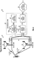
- FIG. 1 shows a wireless communication network 100, which may be an LTE network or some other wireless network.
- Wireless network 100 may include a radio access network (RAN) 120 that supports radio communication and a core network (CN) 140 that supports data communication and/or other services.
- RAN 120 may also be referred to as an Evolved Universal Terrestrial Radio Access Network (E-UTRAN).
- E-UTRAN Evolved Universal Terrestrial Radio Access Network
- RAN 120 may include a number of evolved Node Bs (eNBs) that support radio communication for UEs. For simplicity, only two eNBs 130 and 132 are shown in FIG. 1 .
- An eNB may be an entity that communicates with the UEs and may also be referred to as a Node B, a base station, an access point, etc.
- Each eNB may provide communication coverage for a particular geographic area and may support radio communication for the UEs located within the coverage area.
- the overall coverage area of an eNB may be partitioned into multiple (e.g., three) smaller areas. Each smaller area may be served by a respective eNB subsystem.
- the term "cell" can refer to a coverage area of an eNB and/or an eNB subsystem serving this coverage area.
- RAN 120 may also include other network entities that are not shown in FIG. 1 for simplicity.
- Core network 140 may include a Mobility Management Entity (MME) 142, a Home Subscriber Server (HSS) 144, a serving gateway (SGW) 146, and a Packet Data Network (PDN) gateway (PGW) 148.
- MME Mobility Management Entity
- HSS Home Subscriber Server
- SGW serving gateway
- PGW Packet Data Network gateway
- PGW Packet Data Network gateway
- MME 142 may perform various functions such as control of signaling and security for a Non Access Stratum (NAS), authentication and mobility management of UEs, selection of gateways for UEs, bearer management functions, etc.
- HSS 144 may store subscription-related information (e.g., user profiles) and location information for users, perform authentication and authorization of users, and provide information about user location and routing information when requested.
- Serving gateway 146 may perform various functions related to Internet Protocol (IP) data transfer for UEs such as data routing and forwarding, mobility anchoring, etc. Serving gateway 146 may also terminate the interface towards RAN 120 and may perform various functions such as support for handover between eNBs, buffering, routing and forwarding of data for UEs, initiation of network-triggered service request procedure, accounting functions for charging, etc.
- IP Internet Protocol
- PDN gateway 148 may perform various functions such as maintenance of data connectivity for UEs, IP address allocation, packet filtering for UEs, service level gating control and rate enforcement, dynamic host configuration protocol (DHCP) functions for clients and servers, gateway GPRS support node (GGSN) functionality, etc. PDN gateway 148 may also terminate an SGi interface toward a packet data network 190, which may be the Internet, a packet data network of a network operator, etc. SGi is a reference point between a PDN gateway and a packet data network for provision of data services.
- a packet data network 190 which may be the Internet, a packet data network of a network operator, etc.
- SGi is a reference point between a PDN gateway and a packet data network for provision of data services.
- FIG. 1 also shows exemplary interfaces between various network entities in RAN 120 and core network 140.
- eNBs 130 and 132 may communicate with each other via an X2 interface.
- eNBs 130 and 132 may communicate with MME 142 via an S1-MME interface and with serving gateway 146 via an S1-U interface.
- MME 142 may communicate with HSS 144 via an S6a interface and may communicate with serving gateway 146 via an S11 interface.
- Serving gateway 146 may communicate with PDN gateway 148 via an S5 interface.
- E-UTRA Evolved Universal Terrestrial Radio Access
- E-UTRAN Evolved Universal Terrestrial Radio Access Network
- GPRS General Packet Radio Service
- a UE 110 may communicate with one or more eNBs at any given moment for radio communication.
- UE 110 may be stationary or mobile and may also be referred to as a mobile station, a terminal, an access terminal, a subscriber unit, a station, etc.
- UE 110 may be a cellular phone, a smartphone, a tablet, a wireless communication device, a personal digital assistant (PDA), a wireless modem, a handheld device, a laptop computer, a cordless phone, a wireless local loop (WLL) station, a netbook, a smartbook, etc.
- PDA personal digital assistant
- WLL wireless local loop
- Wireless network 100 may support operation on multiple carriers, which may be referred to as carrier aggregation or multi-carrier operation.
- UE 110 may be configured with multiple carriers for the downlink and one or more carriers for the uplink for carrier aggregation.
- One or more eNBs may transmit data and/or control information on one or more carriers to UE 110.
- UE 110 may transmit data and/or control information on one or more carriers to one or more eNBs.
- Wireless network 100 may support communication via a user plane and a control plane.
- a user plane is a mechanism for carrying data for higher-layer applications and employing a user-plane bearer, which is typically implemented with standard protocols such as User Datagram Protocol (UDP), Transmission Control Protocol (TCP), and Internet Protocol (IP).
- a control plane is a mechanism for carrying data (e.g., signaling) and is typically implemented with network-specific protocols, interfaces, and signaling messages such as Non Access Stratum (NAS) messages and Radio Resource Control (RRC) messages.
- NAS Non Access Stratum
- RRC Radio Resource Control
- traffic/packet data may be sent between UE 110 and wireless network 100 via the user plane.
- Signaling for various procedures to support communication for UE 110 may be sent via the control plane.
- a bearer may refer to an information transmission path of defined characteristics, e.g., capacity, delay, bit error rate, etc.
- a data bearer is a bearer for exchanging data and may terminate at a UE and a network entity (e.g., a PDN gateway) designated to route data for the UE.
- a data bearer may also be referred to as an Evolved Packet System (EPS) bearer in LTE, etc.
- EPS Evolved Packet System
- a data bearer may be established when UE 110 connects to a designated network entity (e.g., a PDN gateway) and may remain established throughout the lifetime of the connection in order to provide UE 110 with always-on IP connectivity.
- This data bearer may be referred to as a default data bearer.
- One or more additional data bearers may be established to the same network entity (e.g., the same PDN gateway) and may be referred to as dedicated data bearer(s).
- Each additional data bearer may be associated with various characteristics such as (i) one or more traffic flow templates (TFTs) used to filter packets to be sent via the data bearer, (ii) quality-of-service (QoS) parameters for data transfer between the UE and the designated network entity, (iii) packet forwarding treatment related to scheduling policy, queue management policy, rate shaping policy, Radio Link Control (RLC) configuration, etc., and/or (iv) other characteristics.
- TFTs traffic flow templates
- QoS quality-of-service
- RLC Radio Link Control
- UE 110 may be configured with one data bearer for transfer of data for a Voice-over-IP (VoIP) call, another data bearer for Internet download traffic, etc.
- a default data bearer may be established with each new data connection (e.g., each new PDN connection) and its context may remain established throughout the lifetime of the data connection.
- the default data bearer may be a non-guaranteed bit rate (GBR) bearer.
- GLR non-guaranteed bit rate
- a dedicated data bearer may be associated with uplink packet filters in a UE and downlink packet filters in a designated network (e.g., a PDN gateway), where the filters may only match certain packets.
- Each data bearer may correspond to a radio bearer.
- the default data bearer may typically be best effort and may carry all packets for an IP address that do not match the packet filters of any of the dedicated data bearers.
- the dedicated data bearers may typically be associated with traffic of a specific type (e.g., based on the packet filters) and may be associated with certain QoS.
- multiple data bearers may be configured for UE 110 for carrier aggregation and may be split among multiple eNBs, which may be referred to as bearer level splitting.
- eNBs may be selected to serve the multiple data bearers of UE 110 based on various criteria such as channel conditions, loading, etc.
- eNBs may be selected to serve data bearers of UE 110 on a per data bearer basis, so that a particular eNB may be selected to serve each data bearer of UE 110.
- Each data packet for UE 110 may be sent via an appropriate data bearer based on a TFT associated with each data bearer.
- Bearer level splitting may be supported in various manners and with various network architectures.
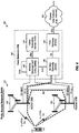
- FIG. 2 shows an exemplary design of bearer level splitting with data bearers terminating at core network 140.
- UE 110 may communicate with multiple eNBs 130 and 132 for carrier aggregation.
- eNB 130 may be an anchor eNB for UE 110, and eNB 132 may be a booster eNB for UE 110.
- An anchor eNB may be an eNB designated to control communication for a UE.
- An anchor eNB may also be referred to as a serving eNB, a primary eNB, a main eNB, etc.
- a booster eNB may be an eNB selected to exchange data with a UE, e.g., transmit data to and/or receive data from the UE.
- a booster eNB may also be referred to as a secondary eNB, a supplemental eNB, etc.
- UE 110 may be configured with multiple data bearers for carrier aggregation. At least one of the multiple data bearers may be served by anchor eNB 130, and remaining ones of the multiple data bearers may be served by booster eNB 132. Each data bearer of UE 110 may thus be served by one eNB for UE 110.
- MME 142 may manage the data bearers of UE 110 and may determine which data bearers of UE 110 are served by which eNBs, e.g., using methods defined in LTE Release 8, except that the tunnel endpoints for the data bearers are now at different eNBs instead of a single eNB. MME 142 may send Modify Bearer Request messages to affected network entities (e.g., serving gateway 146) to change eNBs serving the data bearers of UE 110.
- affected network entities e.g., serving gateway 146
- PDN gateway 148 may receive data intended for UE 110 and may separate the data into different data bearers of UE 110. PDN gateway 148 may forward the data for UE 110 to serving gateway 146, which may forward the data to appropriate eNBs based on a Modify Bearer Request message from MME 142.
- each eNB may receive data from UE 110 and may forward the data to serving gateway 146 via an appropriate data bearer.
- Serving gateway 146 may forward the data for all data bearers of UE 110 to PDN gateway 148.
- MME 142 may be modified for a new type of Path Switch Request (e.g., a Bearer Switch Request), which may impact only a portion of the data bearers of UE 110.
- a Bearer Switch Request e.g., a Bearer Switch Request
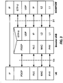
- FIG. 3 shows exemplary protocol stacks for the user plane for communication between UE 110 and PDN gateway 148 based on the network architecture shown in FIG. 2 .
- UE 110 may exchange (e.g., transmit and/or receive) data with PDN gateway 148 via IP.
- IP may operate over (i) Packet Data Convergence Protocol (PDCP), Radio Link Control (RLC), and Medium Access Control (MAC) in Layer 2 (L2) and (ii) E-UTRA air-link in physical layer (PHY)/Layer 1 (LI).
- Booster eNB 132 may communicate with serving gateway 146 via GPRS Tunneling Protocol for User Plane (GTP-U), UDP, IP, L2 and L1.
- GTP-U GPRS Tunneling Protocol for User Plane
- the user plane for UE 110 via booster eNB 132 in FIG. 3 may be similar to the user plane for UE 110 via a conventional eNB in LTE Release 8.
- the user plane for UE 110 via anchor eNB 130 may be similar to the user plane for UE 110 via booster eNB 132.
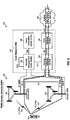
- FIG. 4 shows an exemplary design of bearer level splitting with data bearers terminating at RAN 120.
- UE 110 may communicate with multiple eNBs 130 and 132 for carrier aggregation and may be configured with multiple data bearers for carrier aggregation. At least one of the multiple data bearers may be served by anchor eNB 130, and remaining ones of the multiple data bearers may be served by booster eNB 132.
- Anchor eNB 130 may act as an anchor for the data plane aggregating data of UE 110 sent via booster eNB 132.
- PDCP may terminate at booster eNB 132.
- a single S1 interface between anchor eNB 130 and serving gateway 146 may be used for all data bearers of UE 110.
- the mapping of data bearers to eNBs may be hidden from core network 140, which may operate in the same manner as if all data bearers of UE 110 are served by only eNB 130.
- core network 140 may operate in the same manner as if all data bearers of UE 110 are served by only eNB 130.
- no changes may be needed for network entities in the core network since mobility to and from booster eNBs may be hidden from the core network.
- PDN gateway 148 may receive data intended for UE 110 and may separate the data into different data bearers of UE 110. PDN gateway 148 may forward the data for UE 110 to serving gateway 146, which may forward the data to anchor eNB 130.
- Anchor eNB 130 may identify and separate data for data bearers of UE 110 served by anchor eNB 130 and data for data bearers of UE 110 served by booster eNB 132. Anchor eNB 130 may forward the data for the data bearers served by booster eNB 132 to the booster eNB via X2-U interface.
- the operation performed by anchor eNB 130 may be similar to operations performed by an eNB for handover of UE 110 to booster eNB 132. However, for bearer level splitting, anchor eNB 130 may continue to forward data for UE 110 to booster eNB 132 for the duration of the connection of UE 110 at booster eNB 132.
- anchor eNB 130 may receive data sent by UE 110 via data bearers served by anchor eNB 130.
- Booster eNB 132 may receive data sent by UE 110 via the data bearers served by booster eNB 132 and may forward the data to anchor eNB 130 via the X2-U interface.
- FIG. 5 shows exemplary protocol stacks for the user plane for communication between UE 110 and PDN gateway 148 via eNBs 130 and 132 based on the network architecture shown in FIG. 4 .
- UE 110 may exchange data with PDN gateway 148 via IP.
- IP may operate over PDCP, RLC, MAC, and PHY.
- Booster eNB 132 may communicate with anchor eNB 130 via GTP-U, UDP, IP, L2 and L1.
- anchor eNB 130 may communicate with serving gateway 146 via GTP-U, UDP, IP, L2 and L1.
- the user plane for UE 110 via anchor eNB 130 may be similar to the user plane for UE 110 via booster eNB 132 in FIG. 3 , which may be similar to the user plane for UE 110 via a conventional eNB in LTE Release 8.
- the user plane for UE 110 via anchor eNB 130 may be the same as the user plane for UE 110 via booster eNB 132.
- the user plane for UE 110 via booster eNB 132 may be similar to the user plane for UE 110 via a conventional eNB in LTE Release 8 for data packets sent to anchor eNB 130 that are forwarded to booster eNB 132.
- FIG. 6 shows an exemplary design of bearer level splitting with data bearers terminating at RAN 120.
- the design in FIG. 6 is similar to the design in FIG. 4 , except that PDCP is terminated at anchor eNB 130 in FIG. 6 (instead of at booster eNB 132 in FIG. 4 ).
- Booster eNB 132 may be considered as a cell with regard to UE 110 since it does not terminate PDCP for UE 110 and is not a full eNB to UE 110.
- PDN gateway 148 may receive data intended for UE 110 and may separate the data into different data bearers of UE 110. PDN gateway 148 may forward the data for UE 110 to serving gateway 146, which may forward the data to anchor eNB 130. Anchor eNB 130 may identify and separate data for data bearers served by anchor eNB 130 and data for offloaded data bearers served by booster eNB 132. Anchor eNB 130 may process data for the offloaded data bearers for PDCP and may send the processed data to booster eNB 132 via an X3-U interface.
- booster eNB 132 may receive data sent by UE 110 on the offloaded data bearers and may forward the data to anchor eNB 130 via the X3-U interface.
- X3-U may be a new data plane interface between anchor eNB 130 and booster eNB 132 and may carry PDCP protocol data units (PDUs) on the uplink and downlink over GTP
- PDUs PDCP protocol data units
- Radio Resource Control may be terminated at anchor eNB 130.
- buffered data for PDCP may be available at anchor eNB 130.
- FIG. 7 shows exemplary protocol stacks for the user plane for communication between UE 110 and PDN gateway 148 via eNBs 130 and 132 based on the network architecture shown in FIG. 6 .
- UE 110 may exchange data with PDN gateway 148 via IP.
- IP may operate over PDCP, RLC, MAC, and PHY.
- PDCP may terminate at anchor eNB 130 whereas RLC, MAC, and PHY may terminate at booster eNB 132.
- Booster eNB 132 may communicate with anchor eNB 130 via GTP-U, IP, L2 and L1.
- Anchor eNB 130 may communicate with serving gateway 146 via GTP-U, UDP, IP, L2 and L1.
- the user plane for UE 110 via anchor eNB 130 may be the same as the user plane for UE 110 via booster eNB 132 in FIG. 3 , which may be similar to the user plane for UE 110 via a conventional eNB in LTE Release 8.
- FIG. 8 shows an exemplary design of bearer level splitting with separate data connections in core network 140.
- a data connection is a data path between two entities exchanging data.
- a data connection may also be referred to as a PDN connection, etc.
- a data connection may be associated with various characteristics such as an IP address used to send data to an entity terminating the data connection.
- the IP address may correspond to a packet data network (PDN) requested by a UE for a type of access.
- PDN packet data network
- APN Access Point Name
- an MME may select a PDN that can provide the type of access requested by the UE and then, through a series of procedures defined in TS 23.401, the UE may be assigned an IP address corresponding to that PDN. The PDN may then have one or more associated data bearers so the UE can perform QoS for traffic related to that PDN.
- Bearer level splitting with separate data connections may be used to support multipath TCP.
- TCP typically assumes in-order delivery of data. If a UE sends packets using multiple IP addresses (e.g., for WLAN interface and cellular), then a mechanism is needed to (a) support a TPC client having multiple interfaces and (b) deal with packet loss separately on each interface.
- Multipath TCP is a method of TCP defined by IETF which allows a TCP client to have multiple IP addresses with respect to a TCP server.
- the data bearers of UE 110 for each eNB may correspond to a separate data connection at PDN gateway 148.
- data bearers of UE 110 served by anchor eNB 130 may correspond to a first data connection associated with a first IP address assigned to UE 110
- data bearers of UE 110 served by booster eNB 132 may correspond to a second data connection associated with a second IP address assigned to UE 110.
- all data bearers of UE 110 may correspond to a single data connection at PDN gateway 148.
- a common serving gateway may be used (depending on the control plane) for all data connections of UE 110. This design may simplify bearer management for each data connection as data bearers are activated, de-activated, and/or changed. In another design, different serving gateways may be used for different data connections of UE 110.
- a single PDN gateway may terminate all data connections of UE 110, e.g., as shown in FIG. 8 .
- different PDN gateways may terminate different data connections of UE 110 since (i) UE 110 may be assigned a separate IP address at each eNB and (ii) the data connections for UE 110 may be independent in the data plane.
- Table 1 summarizes various characteristics of bearer level splitting for the three exemplary designs shown in FIGS. 2 , 4 and 6 .
- Table 1 - Bearer Level Splitting Evaluation criteria Data bearers terminated at core network
- Impact MME is updated to None None to core network handle per bearer handover. No changes to PGW/SGW.
- Anchor eNB data plane functions Normal eNB functions for data bearers served by anchor eNB. Normal eNB functions for served data bearers. New X3 interface with booster eNB. Forward data for offloaded data bearers via X2 to booster eNB.
- Routing efficiency Good routing efficiency on downlink and uplink as packets are sent directly to SGW. Routing efficiency is dependent on routing path between anchor eNB and booster eNB. Routing efficiency is dependent on routing path between anchor eNB and booster eNB. Routing bottleneck, if present, will be at anchor eNB and not booster eNB. Routing bottleneck, if present, will be at anchor eNB and not booster eNB. Security Common or independent security for each eNB. Common or independent security for anchor eNB and set of booster eNBs.
- Anchor eNB is aware of security keys for booster eNB. Encrypted data sent on data plane between anchor eNB and UE via booster eNB. Anchor eNB is aware of security keys for booster eNB. CN may be updated to support independent security for more than one booster eNB. Better if booster eNB is not trusted. Coexistence between standalone flow and multi- flow at booster eNB Low complexity. Common data plane - no difference between UE being served by standalone eNB or booster eNB. Medium complexity. Mostly common data plane - UE being served as standalone eNB is sent in S1-U vs. UE being served as booster eNB is sent in X2-U but both are via same GTP protocol. Higher complexity. Separate data plane - UE being served as standalone eNB is sent in S1-U vs. UE being served as booster eNB would forward data packets to anchor eNB for PDCP.
- Data bearers may be terminated at the core network or the RAN, and this choice may be selected based on various criteria such as routing efficiency, impact to the core network, etc. Routing efficiency may also be dependent on how the anchor eNB and booster eNBs are connected in an actual deployment.
- PDCP may be terminated in the anchor eNB or the booster eNB, and this choice may be selected based on various factors such as whether security and RRC are terminated at the anchor eNB or the booster eNB.
- UE 110 may communicate with multiple eNBs for carrier aggregation, e.g., as shown in FIGS. 1 , 2 , 4 , 6 and 8 .
- each eNB that serves data bearers of UE 110 may be considered as a cell.
- One cell may be designated as a primary cell (Pcell) for UE 110, and each remaining cell may be considered as a secondary cell (Scell) for UE 110.
- LTE Release 10 supports carrier aggregation from one or more cells in the same eNB, and coordination among all cells serving UE 110 for carrier aggregation may be possible due to the cells being collocated at the same eNB.
- Multiple data bearers may be configured for UE 110 for carrier aggregation and may be referred to as bearer level aggregation.
- Bearer level aggregation may be combined with carrier aggregation of cells in the same eNB defined in LTE Release 10.
- UE 110 may be served by multiple cells for carrier aggregation, which may include (i) a first subset of cells in the same eNB and (ii) a second subset of cells non-collocated with the first subset of cells (and possibly utilizing a different radio access technology) at a different eNB.
- the first subset of cells may conform to carrier aggregation rules defined in LTE Release 10.
- Bearer level aggregation may be applied to the second subset of cells.
- the functionality of the multiple cells serving UE 110 may be disjoint at lower layers due to latency between eNBs to which these cells belong.
- carrier aggregation in LTE Release 10 may be updated to enable independent cell operation for carrier aggregation.
- hybrid automatic retransmission (HARQ) feedback and periodic channel state information (CSI) feedback from UE 110 may be transmitted to a single cell (e.g., the primary cell).
- Bearer level aggregation may support transmission of control information on the uplink to each cell, so that each cell may operate in similar manner as for single-carrier operation.
- UE 110 may be assigned multiple Physical Uplink Control Channels (PUCCHs) for transmission of control information on the uplink, e.g., one PUCCH for each cell.
- PUCCHs Physical Uplink Control Channels
- UE 110 may perform random access on only the primary cell, e.g., as defined in LTE Release 10.
- UE 110 may perform random access on the primary and secondary cells.
- UE 110 may be configured for discontinuous transmission (DTX) by multiple cells such that good performance can be obtained.
- a single MAC PDU may activate/deactivate multiple cells, e.g., as defined in LTE Release 10. Some coordination among cells may be established to enable multiple cells to be activated/deactivated by a single MAC PDU.
- Separate RLC may be used for each cell serving UE 110, which is different from a single RLC for all cells in LTE Release 10.
- Separate RRC may be used for each cell serving UE 110, which is different from a single RRC for all cells in LTE Release 10.
- Call flows for various procedures may be defined to support bearer level splitting. Some exemplary call flows are described below.
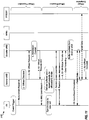
- FIG. 9 shows a call flow 900 for a measurement procedure for identifying booster eNBs with a known physical cell identity (PCI)-to-cell global identity (CGI) mapping.
- PCI physical cell identity
- CGI cell global identity
- each cell may be associated with a PCI and a CGI.
- a PCI is a 9-bit value that is unique for a cell in a particular geographic area.
- a CGI is unique for a cell among all cells in an LTE network.
- Anchor eNB 130 may provide a measurement configuration to UE 110, e.g., when a connection is established by UE 110 or based on some event (step 1).
- the measurement configuration may convey (i) criteria in which UE 110 should make measurements of cells and/or (ii) criteria in which UE 110 should report measurement results of cells to anchor eNB 130.
- UE 110 may be directed to make measurements periodically and/or when triggered by certain events based on the measurement configuration.
- UE 110 may make measurements of cells in response to a trigger event (step 2).
- UE 110 may then send a Measurement Report message to anchor eNB 130.
- the Measurement Report message may include measurement results and PCIs (but not CGIs) of measured cells.
- the measurement results may be for received signal strength/received power, received signal quality, pathloss, geometry, etc.
- the measured cells may be uniquely identified based on the reported PCIs and a known PCI-to-CGI mapping for these cells.
- Anchor eNB 130 may determine the PCI-to-CGI mapping due to automatic neighbor relations (ANR) or based on configuration.
- ANR allows an eNB to find out who its neighbors are and is described in 3GPP 36.300, Section 22.3.2a. If a UE reports a PCI of a target eNB that a source eNB does not have information for, then the source eNB may request the UE to read SIB1 of the target eNB for the reported PCI and find out cell ID, tracking area, etc. The source eNB may then use this information to route HOs to the target eNB and may also use ANR procedures to find out an IP address of the target eNB to establish an X2 connection. Booster eNBs may be selected for UE 110 based on the measurement results and/or other information.
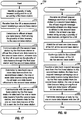
- FIG. 10 shows a call flow 1000 for a measurement procedure for identifying booster eNBs with an unknown PCI-to-CGI mapping.
- Anchor eNB 130 may provide a measurement configuration to UE 110, e.g., when a connection is established by UE 110 or based on some event (step 1).
- UE 110 may make measurements of cells in response to a trigger event (step 2).
- UE 110 may then send a Measurement Report message, which may include measurement results and PCIs (but not CGIs) of measured cells, to anchor eNB 130 (step 3).
- Anchor eNB 130 may not know the CGIs of one or more measured cells based on the reported PCIs (step 4). This may be due to the presence of many cells (which may result in PCI confusion) or the presence of dynamic cells (where the PCIs can change or cells can appear suddenly).
- Anchor eNB 130 may then send a connection reconfiguration message, such as RRCConnectionReconfiguration message, to UE 110 (step 5).
- This RRC message may include a list of PCIs of cells for which CGIs should be reported by UE 110.
- Anchor eNB 130 may assign a measurement gap pattern for UE 110 to acquire system information block type 1 (SIB1) of each cell for which CGI should be reported.
- SIB1 system information block type 1
- UE 110 may return a connection reconfiguration complete message, such as RRCConnectionReconfiguration-Complete message, to anchor eNB 130 (step 6).
- UE 110 may read system information, such as from SIB1, of each cell for which CGI should be reported (e.g., during measurement gaps assigned by anchor eNB 130) and may obtain CGI of each cell based on the system information of the cell (step 7). UE 110 may then send a Measurement Report message with the CGIs of the cells for which CGIs should be reported (step 8). Booster eNBs may be selected for UE 110 based on the measurement results and/or other information.
- SIB1 system information
- Booster eNBs may be selected for UE 110 based on the measurement results and/or other information.
- FIG. 11 shows a design of a call flow 1100 for offloading data bearers from anchor eNB 130 to booster eNB 132 for data bearers terminated at RAN 120.
- Call flow 1100 may be applicable for the network architecture shown in FIG. 4 or 6 and may assume that no RRC is available at booster eNB 132.
- Call flow 1100 includes an offload preparation phase, an offload execution phase, and an offload completion phase.
- Anchor eNB 130 may provide a measurement configuration to UE 110 to make measurements of cells (not shown in FIG. 11 ).
- UE 110 may make measurements of cells when triggered by an event and may report measurement results to anchor eNB 130 (step 1).
- UE 110 may read the system information, such as through SIB1, of measured cells to obtain CGIs of these cells (if necessary), and the CGIs may be used to unambiguously identify these cells.
- Anchor eNB 130 may determine which data bearers to offload to booster eNB 132 based on the measurement results and/or other information (step 2). For step 2, anchor eNB 130 may determine which evolved Radio Access Bearers (E-RABs) to offload to booster eNB 132. There may be a one-to-one mapping between an E-RAB and a data bearer. Anchor eNB 130 may then send an OFFLOAD REQUEST message (which may be similar to a HANDOVER REQUEST message) to booster eNB 132 (step 3). An OFFLOAD REQUEST may be any type of message to serve the data at another eNB other than the serving eNB, such as anchor eNB 130.
- E-RABs evolved Radio Access Bearers
- the OFFLOAD REQUEST message may include a list of data bearers to be offloaded and pertinent information for each data bearer such as QoS information, an indication that anchor eNB 130 proposes to forward downlink data, TNL IP address information, GTP Tunnel Endpoint ID (TEID), etc.
- the QOS information may include a QoS Class Identifier (QCI), allocation and retention priority (ARP) which indicates a priority for access control (or which data bearers to drop first if a cell becomes congested), GBR QoS Information that may indicate a maximum bit rate and a guaranteed bit rate of a GBR bearer for downlink and uplink, etc.
- QCI QoS Class Identifier
- ARP allocation and retention priority
- GBR QoS Information may indicate a maximum bit rate and a guaranteed bit rate of a GBR bearer for downlink and uplink, etc.
- the TNL IP address information may include an IP address that each side may use for a GTP tunnel for a data bearer, e.g., an eNB may use a separate IP address for each type of QCI.
- the TEID may identify a tunnel for a data bearer on each side.
- Anchor eNB 130 may or may not include GTP-U addressing information of serving gateway 146 and/or PDN gateway 148 since booster eNB 132 will use the X2 interface to anchor eNB 130 and not the S1 interface to core network 140.
- Booster eNB 132 may receive the OFFLOAD REQUEST message from anchor eNB 130 and may perform admission control for the list of data bearers sent by anchor eNB 130 (step 4). Booster eNB 132 may then return an acknowledgment message, such as OFFLOAD REQUEST ACK message, (which may be similar to a HANDOVER REQUEST ACK message) to anchor eNB 130 (step 5).
- the OFFLOAD REQUEST ACK message may include a booster eNB to anchor eNB transparent container and a list of data bearers setup.
- the transparent container may include a command message, such as an OffloadCommand message, which may be similar to a HandoverCommand message.
- the list of data bearers setup may include pertinent information for each data bearer such as (i) GTP-U addressing information for booster eNB downlink, which may be used by anchor eNB 130 to forward downlink data for the data bearers to booster eNB 132, and (ii) GTP-U addressing information for booster eNB uplink, which may be used by booster eNB 132 to forward uplink data for UE 110 to anchor eNB 130.
- GTP-U addressing information for booster eNB downlink which may be used by anchor eNB 130 to forward downlink data for the data bearers to booster eNB 132
- GTP-U addressing information for booster eNB uplink which may be used by booster eNB 132 to forward uplink data for UE 110 to anchor eNB 130.
- Anchor eNB 130 may send a connection reconfiguration message, such as RRCConnectionReconfiguration message, to UE 110 (step 6).
- This message may include dedicated radio resource configuration information for the list of data bearers being offloaded to booster eNB 132.
- UE 110 may reset MAC and may re-establish PDCP and RLC for all data bearers being offloaded to booster eNB 132.
- UE 110 may operate in an RRC_CONNECTED state and may send a contention-free random access preamble (RAP) on a random access channel (RACH) to booster eNB (step 7).
- Booster eNB 132 may receive the random access preamble from UE 110 and may validate a signature sequence in the random access preamble.
- Booster eNB 132 may then send a random access response to UE 110 (step 8).
- the random access response may be addressed to an appropriate Cell Radio Network Temporary Identity (C-RNTI) on a PDCCH assigned to UE 110 by booster eNB 132.
- C-RNTI Cell Radio Network Temporary Identity
- Anchor eNB 130 may send a status transfer message, such as SN STATUS TRANSFER message, to booster eNB 132 to convey uplink PDCP SN receiver status and downlink PDCP SN transmitter status of data bearers for which PDCP status preservation applies, e.g., data bearers with RLC acknowledged mode (AM) (step 9).
- Anchor eNB 130 may send this message only if at least one data bearer with RLC-AM is being offloaded to booster eNB 132.
- Anchor eNB 130 may begin to forward, in order, downlink data for the offloaded data bearers (which may be stored in data bearer buffers at anchor eNB 130) to booster eNB 132. Step 9 and data forwarding by anchor eNB 130 may occur at any time after step 6, e.g., in parallel and immediately following step 6.
- UE 110 may send a connection reconfiguration complete message, such as RRCConnectionReconfigurationComplete message, to anchor eNB 130 (step 10).
- Booster eNB 132 may send control information on a PDCCH to the UE.
- the control information may include an uplink grant for a new transmission.
- the PDCCH may be addressed to a C-RNTI assigned to UE 110 by booster eNB 132 and sent in the connection reconfiguration message in step 6.
- UE 110 may thereafter send uplink data and receive downlink data for all offloaded data bearers via booster eNB 132.
- Booster eNB 132 may send a completion message, such as UE OFFLOAD COMPLETE message, (which may be similar to a UE CONTEXT RELEASE message) to anchor eNB 130 (step 11).
- This message may include an eNB UE X2AP ID for anchor eNB 130 and an eNB UE X2AP ID for booster eNB 132.
- FIG. 12 shows a design of a call flow 1200 for offloading data bearers from anchor eNB 130 to booster eNB 132 for data bearers terminated at core network 140.
- Call flow 1200 may be applicable for the network architecture shown in FIG. 2 .
- Call flow 1200 includes steps 1 to 11 that correspond to steps 1 to 11 in call flow 1100 in FIG. 11 .
- Call flow 1200 further includes additional steps to modify data bearers in core network 140 to route data for UE 110 to and from serving gateway 146.
- booster eNB 132 may send a switch request message, such as E-RAB SWITCH REQUEST message, (which may be similar to a PATH SWITCH REQUEST message) to MME 142 for E-RABs corresponding to data bearers being offloaded to booster eNB 132 (step 12).
- the E-RAB SWITCH REQUEST message may include an MME UE S1AP ID, an eNB UE S1AP ID for booster eNB 132, a list of data bearers being offloaded, and pertinent information for each data bearer, which may include GTP-U addressing information for booster eNB downlink and uplink.
- booster eNB 132 may send an E-RAB SWITCH REQUEST message to MME 142 after step 9.
- the MME 142 may receive the E-RAB SWITCH REQUEST message and may send a Modify Bearer Request message to serving gateway 146/PDN gateway 148 (step 13).
- the Modify Bearer Request message may include the list of data bearers being offloaded, pertinent information for each data bearer, address information for booster eNB 132, etc.
- the pertinent information for each data bearer may include a data bearer ID for each data bearer, e.g., data bearer IDs for the default data bearer and all dedicated data bearers.
- the address information may include a Tunnel End Point Identifier (TEID) and an IP address of booster eNB 132 for the user plane, which may be used to uniquely identify the default data bearer and the dedicated data bearers for UE 110.
- TEID Tunnel End Point Identifier
- Serving gateway 146/PDN gateway 148 may receive the Modify Bearer Request message from MME 142 and may send one or more GTP-U 'End Marker' packets to anchor eNB 130. Serving gateway 146/PDN gateway 148 may also begin to send downlink data for the offloaded data bearers directly to booster eNB 132. Anchor eNB 130 may send one or more GTP-U 'End Marker' packets to booster eNB 132. Booster eNB 132 may receive downlink data for the offloaded data bearers directly from serving gateway 146/PDN gateway 148 and may begin to send the downlink data for the offloaded data bearers to UE 110.
- Serving gateway 146/PDN gateway 148 may send a Modify Bearer Response message to MME 142 (step 14).
- MME 142 may send a switch request acknowledgement message, such as E-RAB SWITCH REQUEST ACK message, (which may be similar to a PATH SWITCH REQUEST ACK message) to booster eNB 132 (step 15).
- FIG. 13 shows a design of a call flow 1300 for modifying handling of the data bearers from booster eNB 132 by anchor eNB 130 for data bearers terminated at RAN 120.
- Call flow 1300 may be applicable for the network architecture shown in FIG. 4 or 6 and may assume that no RRC is available at booster eNB 132.
- Call flow 1300 includes a modify handling preparation phase, a modify handling execution phase, and a modify handling completion phase.
- UE 110 may send a measurement report to anchor eNB 130 in response to a trigger event, which may be determined by a measurement configuration of UE 110 (step 1).
- the measurement report may include measurement results for one or more cells served by booster eNB 132 and/or other cells.
- Anchor eNB 130 may determine to modify handling of all data bearers of UE 110 that have been offloaded to booster eNB 132 (step 2).
- anchor eNB 130 may decide to modify handling of only a subset of the data bearers that have been offloaded to booster eNB 132.
- anchor eNB 130 may decide to direct handling of the all or a subset of the offloaded data bearers to one or more other booster eNBs.
- An offloading procedure e.g., in FIG. 11 or 12
- a modify handling procedure may be used to change which data bearers to offload to booster eNB 132 while maintaining an active connection with booster eNB 132.
- Anchor eNB 130 may send a handling modification request message, such as MODIFY HANDLING REQUEST message, to booster eNB 132 (step 3).
- the MODIFY HANDLING REQUEST message may include a list of data bearers that are no longer offloaded and/or a list of additional data bearers to be offloaded.
- the message may also include pertinent information for each additional offloaded data bearer such as QoS information, an indication that anchor eNB 130 proposes to forward downlink data for the data bearer, etc.
- anchor eNB 130 may send offload requests to one or more other booster eNBs, such as booster eNBs 1301 and 1302 (alternative steps 3a and 3b) and inform booster eNB 132 in the message that the data bearers will be forwarded to booster eNBs 1301 and 1302.
- booster eNB 132 may receive the message from anchor eNB 130 and may return an acknowledgement message, such as MODIFY HANDLING REQUEST ACK message, to anchor eNB 130 (step 4).
- Anchor eNB 130 may send connection reconfiguration message, such as RRCConnectionReconfiguration message, to UE 110 (step 5).
- This message may include dedicated radio resource configuration information for the list of data bearers whose handling is being modified by anchor eNB 130.
- the message may indicate to release the data bearers at booster eNB 132 and to reconfigure the data bearers to be used at anchor eNB 130 or one or more of booster eNBs 1301 and 1302 or a combination thereof.
- UE 110 may receive the connection reconfiguration message from anchor eNB 130 and may reset MAC and re-establish PDCP and RLC for all data bearers whose handling is being modified.
- Booster eNB 132 may send a transfer status message, such as SN STATUS TRANSFER message, to anchor eNB 130 to convey uplink PDCP SN receiver status and downlink PDCP SN transmitter status of E-RABs for which PDCP status preservation applies, e.g., for data bearers with RLC-AM (step 6).
- Booster eNB 132 sends this message only if at least one data bearer is RLC-AM was offloaded to booster eNB 132.
- Booster eNB 132 may begin forwarding, in order, downlink data for data bearers whose handling is being modified (which may be stored in data bearer buffers) to anchor eNB 130 or the base station who will be handling the offloaded data bearers.
- anchor eNB 130 may have buffered the downlink data for UE 110, and so the data does not need to be forwarded by booster eNB 132.
- Step 6 and data forwarding by booster eNB 132 may occur at any time after step 4, e.g., in parallel and immediately following step 4.
- UE 110 may send a connection reconfiguration complete message, such as RRCConnectionReconfigurationComplete message, to anchor eNB 130 (step 7). If there are no remaining E-RABs for UE 110 at booster eNB 132, then UE 110 may stop communicating with booster eNB 132 and may release any related resources assigned to UE 110 by booster eNB 132.
- a connection reconfiguration complete message such as RRCConnectionReconfigurationComplete message
- the packet data exchanged with UE 110 may be exchanged with booster eNBs 1301 and 1302, in addition to or instead of from anchor eNB 130.
- Anchor eNB 130 may send a handling modification complete message, such as UE MODIFY HANDLING COMPLETE message, (which may be similar to a UE CONTEXT RELEASE message) to booster eNB 132 (step 8).
- the UE handling modification complete message may include an eNB UE X2AP ID for anchor eNB 130 or any of the other base stations now handling the offloaded bearers from booster eNB 132 and an eNB UE X2AP ID for booster eNB 132.
- FIG. 14 shows a design of a call flow 1400 for taking back data bearers from booster eNB 132 by anchor eNB 130 for data bearers terminated at core network 140.
- Call flow 1400 may be applicable for the network architecture shown in FIG. 2 and may assume that no RRC is available at booster eNB 132.
- Call flow 1400 includes steps 1 to 8 that correspond to steps 1 to 8 in call flow 1300 in FIG. 13 .
- Call flow 1400 further includes additional steps to modify data bearers in core network 140 to route data for UE 110 to and from serving gateway 146.
- Anchor eNB 130 may send an E-RAB SWITCH REQUEST message to MME 142 for data bearers to be offloaded (which may exclude data bearers whose handling is being modified).
- This message may include an MME UE S1AP ID for MME 142, an eNB UE S1AP ID for booster eNB 132, a list of data bearers to be offloaded, and pertinent information for each data bearer such as eNB GTP-U addressing information (step 9).
- Step 9 may occur any time after (e.g., immediately following) steps 6 and 7.
- MME 142 may send a Modify Bearer Request message to serving gateway 146/PDN gateway 148.
- This message may include the list of data bearers to be offloaded and pertinent information for each data bearer such as a data bearer ID (e.g., data bearer IDs for the default data bearer and all dedicated data bearers), TEID and IPv4 address of anchor eNB 130 for the user plane (which may be used to uniquely identify the default data bearer and the dedicated data bearers of UE 110), and/or other information.
- a data bearer ID e.g., data bearer IDs for the default data bearer and all dedicated data bearers
- TEID and IPv4 address of anchor eNB 130 for the user plane which may be used to uniquely identify the default data bearer and the dedicated data bearers of UE 110
- Serving gateway 146/PDN gateway 148 may receive the Modify Bearer Request message from MME 142 and may send one or more GTP-U 'End Marker' packets to booster eNB 132. Serving gateway 146/PDN gateway 148 may also begin to send downlink data (e.g., directly) to anchor eNB 130 for data bearers whose handling is being modified. Booster eNB 132 may forward one or more GTP-U 'End Marker' packets to anchor eNB 130. Anchor eNB 130 may thereafter receive downlink data for the offloaded data bearers of UE 110 from serving gateway 146/PDN gateway 148 and may send the data to UE 110.
- downlink data e.g., directly
- Booster eNB 132 may forward one or more GTP-U 'End Marker' packets to anchor eNB 130.
- Anchor eNB 130 may thereafter receive downlink data for the offloaded data bearers of UE 110 from serving gateway 146/PDN gateway 148 and may
- Serving gateway 146/PDN gateway 148 may send a Modify Bearer Response message to MME 142 (step 11).
- MME 142 may send an E-RAB SWITCH REQUEST ACK message to anchor eNB 130 (step 12).
- FIG. 15 shows a design of a call flow 1500 for adding or removing data bearers at booster eNB 132 for data bearers terminated at RAN 120.
- Call flow 1500 may be applicable for the network architecture shown in FIG. 4 or 6 and may assume that no RRC is available at booster eNB 132.
- UE 110 may send a measurement report to anchor eNB 130 in response to a trigger event, which may be determined by a measurement configuration of UE 110 (step 1).
- the measurement report may include measurement results for one or more cells served by booster eNB 132 and/or other cells.
- Anchor eNB 130 may determine a list of E-RABs to be added and/or a list of E-RABs to be removed at booster eNB 132 (step 2).
- Each E-RAB may be associated with a data bearer of UE 110 to be added or removed at booster eNB 132.
- Anchor eNB 130 may send a MODIFY E-RABs REQUEST message (which may be similar to a HANDOVER REQUEST message) to booster eNB 132 (step 3).
- the MODIFY E-RABs REQUEST message may include a list of data bearers to be added to the data bearers (if any) already served by booster eNB 132 (i.e., a list of data bearers to offload) and/or a list of data bearers to no longer be served by booster eNB 132 and/or (a list of data bearers whose handling should being modified).
- the message may also include pertinent information for each data bearer to be added such as QoS information, an indication that anchor eNB 130 proposes to forward downlink data for UE 110, etc.
- Anchor eNB 130 may or may not include GTP-U addressing information for serving gateway 146 and PDN gateway 148 since booster eNB 132 may use the X2 interface to anchor eNB 130 and not the S1 interface.
- Booster eNB 132 may perform admission control for the list of data bearers to be added as sent by anchor eNB 130 (step 4).
- Booster eNB 132 may send a MODIFY E-RABs REQUEST ACK message (which may be similar to a HANDOVER REQUEST message) to anchor eNB 130 (step 5).
- the MODIFY E-RABs REQUEST ACK message may include a booster eNB to anchor eNB transparent container, a list of data bearers to be added to booster eNB 132, and pertinent information for each data bearer.
- the transparent container may include a ModifyCommand message (which may be similar to a HandoverCommand message).
- the pertinent information for each data bearer may include (i) booster eNB DL GTP-U addressing information, which may be used by anchor eNB 130 to forward downlink data for the added offloaded data bearers to booster eNB 132, and (ii) booster eNB UL GTP-U addressing information, which may be used by booster eNB 132 to forward uplink data for the added offloaded data bearers to anchor eNB 130.
- Anchor eNB 130 may send an RRCConnectionReconfiguration message to UE 110 (step 6).
- This message may include dedicated radio resource configuration information for the data bearers to be added at booster eNB 132 and the data bearers to be removed from booster eNB 132 and served at anchor eNB 130.
- UE 110 may reset MAC and re-establish PDCP and RLC for all data bearers to be added or removed at the booster eNB 132.
- Anchor eNB 130 may send an SN STATUS TRANSFER message to booster eNB 132 to convey uplink PDCP SN receiver status and downlink PDCP SN transmitter status of the added E-RABs for which PDCP status preservation applies, e.g., data bearers with RLC-AM (step 7).
- Anchor eNB 130 may send this message only if at least one data bearer with RLC-AM is added to the list of data bearers offloaded booster eNB 132.
- Anchor eNB 130 may begin to forward, in order, downlink data for the added offloaded data bearers (which may be stored in data bearer buffers) to booster eNB 132.
- Booster eNB 132 may send an SN STATUS TRANSFER message to anchor eNB 130 to convey uplink PDCP SN receiver status and downlink PDCP SN transmitter status of E-RABs for which PDCP status preservation applies (step 8). Booster eNB 132 may send this message only if at least one data bearer with RLC-AM was removed. Booster eNB 132 may begin to forward, in order, downlink data for UE 110 for the removed data bearers (which may be stored in data bearer buffers) to anchor eNB 132. Step 8 and the data forwarding may occur any time (e.g., in parallel and immediately) after step 5. Alternatively, anchor eNB 130 may have buffered the downlink data for UE 110, and booster eNB 132 may not need to forward the downlink data for UE 110.
- UE 110 may send an RRCConnectionReconfigurationComplete message to anchor eNB 130 (step 9).
- Anchor eNB 130 may send a MODIFY E-RABs COMPLETE message to booster eNB 132 (step 10).
- FIG. 16 shows a design of a call flow 1600 for adding or removing data bearers at booster eNB 132 for data bearers terminated at core network 140.
- Call flow 1600 may be applicable for the network architecture shown in FIG. 2 and may assume that no RRC is available at booster eNB 132.
- Call flow 1600 includes steps 1 to 10 that correspond to steps 1 to 10 in call flow 1500 in FIG. 15 .
- Call flow 1600 further includes additional steps to modify data bearers in core network 140 to route data for UE 110 to and from serving gateway 146.
- Anchor eNB 130 may send an E-RAB SWITCH REQUEST message to MME 142 for data bearers to be added or removed at booster eNB 132 (step 11).
- This message may include an MME UE S1AP ID for MME 142, an eNB UE S1AP ID for booster eNB 132, a list of data bearers to be modified, and pertinent information for each data bearer such as eNB GTP-U addressing information.
- MME 142 may send a Modify Bearer Request message to serving gateway 146/PDN gateway 148 (step 12).
- This message may include the list of data bearers to be modified and pertinent information for each data bearer such as data bearer ID (e.g., data bearer IDs for the default data bearer and all dedicated data bearers).
- This message may also include, for added data bearers, the TEID and IPv4 address of booster eNB 132 for the user plane.
- This message may also include, for removed data bearers, the TEID and IPv4 address of anchor eNB 130 for the user plane.
- serving gateway 146/PDN gateway 148 may send one or more GTP-U 'End Marker' packets to anchor eNB 130 for added offloaded data bearers and to booster eNB 132 for removed offloaded data bearers.
- Serving gateway 146/PDN gateway 148 may begin to send (i) downlink data for the added offloaded data bearers directly to booster eNB 132 and (ii) downlink data for the removed data bearers directly to anchor eNB 130.
- anchor eNB 130 may forward one or more GTP-U 'End Marker' packets to booster eNB 132.
- Booster eNB 132 may thereafter receive downlink data for the added offloaded data bearers from serving gateway 146/PDN gateway 148 and may send the downlink data to UE 110.
- booster eNB 132 may forward one or more GTP-U 'End Marker' packets to anchor eNB 130.
- Anchor eNB may thereafter receive downlink data for the removed offloaded data bearers from serving gateway 146/PDN gateway 148 and may send the downlink data to UE 110.
- Serving gateway 146/PDN gateway 148 may send a Modify Bearer Response message to MME 142 (step 13).
- MME 142 may send an E-RAB SWITCH REQUEST ACK message to anchor eNB 130 (step 14).
- FIG. 17 shows a design of a process 1700 for supporting communication in a wireless network.
- Process 1700 may be performed by a first base station/eNB (as described below) or by some other entity.
- the first base station may identify a plurality of data bearers configured for a UE served by the first base station (block 1712).
- the first base station may be an anchor eNB for the UE.
- the plurality of data bearers may carry data sent via a plurality of carriers configured for the UE for carrier aggregation.
- the first base station may receive from the UE a measurement report identifying a second base station (block 1714).
- the first base station may determine to offload at least one data bearer, from among the plurality of data bearers, to the second base station (block 1716).
- the first base station may communicate with the second base station to offload the at least one data bearer to the second base station (block 1718).
- Data for the UE may be sent via the plurality of data bearers through the first
- the first base station may send an offload request message to the second base station (e.g., in step 3 in FIG. 11 or 12 ).
- the offload request message may convey the at least one data bearer being offloaded to the second base station.
- the offload request message may also include QoS information and/or other information for the at least one data bearer.
- the first base station may forward data for the at least one data bearer to the second base station.
- the first base station may send a reconfiguration message to the UE (e.g., in step 6 in FIG. 11 or 12 ).
- the reconfiguration message may include radio resource configuration information for at least one radio access bearer associated with the at least one data bearer being offloaded to the second base station.
- a switch request message may be sent from the second base station to a MME (e.g., in step 12 in FIG. 12 ) to convey the at least one data bearer being offloaded to the second base station.
- the first base station may determine to modify handling of one or more data bearers from the second base station (block 1720).
- the one or more data bearers may be among the at least one data bearer offloaded to the second base station. In general, all or a subset of the offloaded data bearers may have their handling modified.
- the first base station may communicate with the second base station to modify handling of the one or more data bearers from the second base station, (block 1722). Data for the one or more data bearers of the UE may thereafter be sent via the first base station.
- the first base station may send a modify handling request message to the second base station (e.g., in step 3 in FIG. 13 or 14 ).
- the modify handling request message may convey the one or more data bearer whose handling is being modified from the second base station.
- the first base station may receive data for the one or more data bearers forwarded from the second base station to the first base station.
- the first base station may send a reconfiguration message to the UE (e.g., in step 5 in FIG. 13 or 14 ).
- the reconfiguration message may include radio resource configuration information for one or more radio access bearers associated with the one or more data bearers whose handling is being modified from the second base station.
- the first base station may send a switch request message to the MME (e.g., in step 9 in FIG. 14 ).
- the switch request message may convey the one or more data bearers whose handling is being modified from the second base station.
- the first base station may determine to modify (e.g., to offload or to modify handling) one or more data bearers of the UE (e.g., in step 3 in FIG. 15 or 16 ). The first base station may then communicate with the second base station to modify the one or more data bearers of the UE.
- modify e.g., to offload or to modify handling
- the plurality of data bearers of the UE may be terminated at a core network serving the first and second base stations, e.g., as shown in FIG. 2 .
- the plurality of data bearers of the UE may be terminated at a RAN including the first and second base stations, e.g., as shown in FIGS. 4 and 6 .
- the procedure for offloading data bearers and the procedure for taking back data bearers may be performed in different manners depending on whether the data bearers are terminated at the core network or the RAN, e.g., as shown in FIGS. 11 to 16 .
- the first base station may receive a measurement report from the UE and may identify the second base station to offload the at least one data bearer in block 1716 based on the measurement report.
- the first base station may obtain a PCI for the second base station from the measurement report and may identify the second base station based on the PCI.
- the first base station may obtain a CGI for the second base station from the measurement report and may identify the second base station based on the CGI.
- FIG. 18 shows a design of a process 1800 for supporting communication in a wireless network.
- Process 1800 may be performed by a second base station/eNB (as described below) or by some other entity.
- the second base station may receive an offload request message sent by a first base station (e.g., in step 3 in FIG. 11 or 12 ) (block 1812).
- the offload request message may convey at least one data bearer to offload to the second base station.
- the at least one data bearer may be among a plurality of data bearers configured for a UE, e.g., for carrier aggregation.
- the first base station may be an anchor eNB for the UE, and the second base station may be a booster eNB for the UE.
- the second base station may admit the at least one data bearer of the UE (e.g., in step 4 in FIG. 11 or 12 ) (block 1814).
- the second base station may receive downlink data for the at least one data bearer from the first base station.
- the second base station may thereafter exchange (e.g., send and/or receive) data for the at least one data bearer of the UE (block 1816).
- the second base station may receive a modify handling request message from (e.g., in step 3 in FIG. 13 or 14 ) (block 1818).
- the modify handling request message may convey one or more data bearers whose handling is being modified by the first base station from the second base station.
- the one or more data bearers may be among the at least one data bearer offloaded to the second base station.
- the second base station may forward downlink data for the one or more data bearers to the first base station and may stop exchanging data for the one or more data bearers (block 1820).
- the second base station may receive a modify request message from the first base station (e.g., in step 3 in FIG. 15 or 16 ).
- the modify request message may convey one or more data bearers being offloaded to or whose handling is being modified from the second base station.
- the second base station may (i) receive downlink data for the one or more data bearers if they are being offloaded to the second base station or (ii) forward downlink data for the one or more data bearers if they are whose handling is being modified by the first base station.
- FIG. 19 shows a design of a process 1900 for communicating in a wireless network.
- Process 1900 may be performed by a UE (as described below) or by some other entity.
- the UE may receive a first reconfiguration message from a first base station (e.g., in step 6 in FIG. 11 or 12 ) (block 1912).
- the first reconfiguration message may include first radio resource configuration information for at least one radio access bearer associated with at least one data bearer being offloaded from the first base station to a second base station.
- the at least one data bearer may be among a plurality of data bearers configured for the UE for carrier aggregation.
- the first base station may be an anchor eNB for the UE, and the second base station may be a booster eNB for the UE.
- the UE may access the second base station (e.g., via a RACH) in response to the first reconfiguration message (e.g., in step 7 in FIG. 11 or 12 ) (block 1914).
- the UE may thereafter exchange (e.g., send and/or receive) data for the at least one data bearer of the UE via the second base station (block 1916).
- the UE may receive a second reconfiguration message from the first base station (in step 5 in FIG. 14 or 15 ) (block 1918).
- the second reconfiguration message may include second radio resource configuration information for one or more radio access bearers associated with one or more data bearers whose handling is being modified from the second base station.
- the one or more data bearers may be among the at least one data bearer offloaded to the second base station.
- the UE may stop communicating with the second base station for the one or more data bearers and may exchange data for the one or more data bearers of the UE via the first base station (block 1920).
- the UE may receive a third reconfiguration message from the first base station (in step 6 in FIG. 15 or 16 ).
- the third reconfiguration message may include third radio resource configuration information for one or more radio access bearers associated with one or more data bearers of the UE being offloaded to the second base station or whose handling is being modified from the second base station.
- the UE may (i) start communicating with the second base station for the one or more data bearers if they are being offloaded or (ii) stop communicating with the second base station for the one or more data bearers if they are whose handling is being modified.
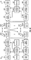
- FIG. 20 shows a block diagram of an exemplary design of UE 110 and eNB/base station 130 in FIG. 1 .
- eNB 130 may be equipped with T antennas 2034a through 2034t
- UE 110 may be equipped with R antennas 2052a through 2052r, where in general T ⁇ 1 and R ⁇ 1.
- a transmit processor 2020 may receive data for one or more UEs from a data source 2012 and control information from a controller/processor 2040.
- Data source 2012 may implement data buffers for all data bearers configured for UE 110 and other UEs served by eNB 130.
- Transmit processor 2020 may process (e.g., encode, interleave, and symbol map) the data and control information to obtain data symbols and control symbols, respectively. Transmit processor 2020 may also generate reference symbols for one or more reference signals.
- a transmit (TX) multiple-input multiple-output (MIMO) processor 2030 may perform spatial processing (e.g., precoding) on the data symbols, the control symbols, and/or the reference symbols, if applicable, and may provide T output symbol streams to T modulators (MODs) 2032a through 2032t.
- Each modulator 2032 may process a respective output symbol stream (e.g., for OFDM, SC-FDMA, CDMA, etc.) to obtain an output sample stream.
- Each modulator 2032 may further process (e.g., convert to analog, amplify, filter, and upconvert) the output sample stream to obtain an uplink signal.
- T uplink signals from modulators 2032a through 2032t may be transmitted via T antennas 2034a through 2034t, respectively.
- antennas 2052a through 2052r may receive the downlink signals from eNB 130 and other eNBs and may provide received signals to demodulators (DEMODs) 2054a through 2054r, respectively.
- Each demodulator 2054 may condition (e.g., filter, amplify, downconvert, and digitize) a respective received signal to obtain received samples.
- Each demodulator 2054 may further process the received samples to obtain received symbols.
- a MIMO detector 2056 may obtain received symbols from all R demodulators 2054a through 2054r and may perform MIMO detection on the received symbols to obtain detected symbols.
- a receive processor 2058 may process (e.g., symbol demap, deinterleave, and decode) the detected symbols, provide decoded data to a data sink 2060, and provide decoded control information to a controller/ processor 2080.
- data from a data source 2062 and control information from controller/processor 2080 may be processed by a transmit processor 2064, precoded by a TX MIMO processor 2066 if applicable, conditioned by modulators 2054a through 2054r, and transmitted to eNB 130 and other eNBs.
- the uplink signals from UE 110 and other UEs may be received by antennas 2034, conditioned by demodulators 2032, processed by a MIMO detector 2036, and further processed by a receive processor 2038 to obtain the data and control information sent by UE 110 and other UEs.
- Processor 2038 may provide the decoded data to a data sink 2039 and the decoded control information to controller/processor 2040.
- Controllers/processors 2040 and 2080 may direct the operation at eNB 130 and UE 110, respectively.
- Memories 2042 and 2082 may store data and program codes for eNB 130 and UE 110, respectively.
- a scheduler 2044 may schedule UE 110 and other UEs for data transmission on the downlink and uplink and may assign resources to the scheduled UEs.
- Processor 2040 and/or other processors and modules at eNB 130 may perform or direct the operation performed by eNB 130 in call flow 900 in FIG. 9 , call flow 1000 in FIG. 10 , call flow 1100 in FIG. 11 , call flow 1200 in FIG. 12 , call flow 1300 in FIG. 13 , call flow 1400 in FIG. 14 , call flow 1500 in FIG. 15 , call flow 1600 in FIG.
- Processor 2080 and/or other processors and modules at UE 110 may perform or direct the operation of UE 110 in call flows 900, 1000, 1100, 1200, 1300, 1400, 1500 and 1600, process 1900 in FIG. 19 , and/or other call flows and processes for the techniques described herein data transmission on the downlink.
- eNB 132 may be implemented in similar manner as eNB 130.
- One or more processors and/or modules at eNB 132 may perform or direct the operation performed by eNB 132 in call flows 900, 1000, 1100, 1200, 1300, 1400, 1500 and 1600, processes 1700 and 1800, and/or other processes for the techniques described herein.
- DSP digital signal processor
- ASIC application specific integrated circuit
- FPGA field programmable gate array
- a general-purpose processor may be a microprocessor, but in the alternative, the processor may be any conventional processor, controller, microcontroller, or state machine.
- a processor may also be implemented as a combination of computing devices, e.g., a combination of a DSP and a microprocessor, a plurality of microprocessors, one or more microprocessors in conjunction with a DSP core, or any other such configuration.
- a software module may reside in RAM memory, flash memory, ROM memory, EPROM memory, EEPROM memory, registers, hard disk, a removable disk, a CD-ROM, or any other form of storage medium known in the art.
- An exemplary storage medium is coupled to the processor such that the processor can read information from, and write information to, the storage medium.
- the storage medium may be integral to the processor.
- the processor and the storage medium may reside in an ASIC.
- the ASIC may reside in a user terminal.
- the processor and the storage medium may reside as discrete components in a user terminal.
- the functions described may be implemented in hardware, software, firmware, or any combination thereof. If implemented in software, the functions may be stored on or transmitted over as one or more instructions or code on a computer-readable medium.
- Computer-readable media includes both computer storage media and communication media including any medium that facilitates transfer of a computer program from one place to another.
- a storage media may be any available media that can be accessed by a general purpose or special purpose computer.
- such computer-readable media can comprise RAM, ROM, EEPROM, CD-ROM or other optical disk storage, magnetic disk storage or other magnetic storage devices, or any other medium that can be used to carry or store desired program code means in the form of instructions or data structures and that can be accessed by a general-purpose or special-purpose computer, or a general-purpose or special-purpose processor. Also, any connection is properly termed a computer-readable medium.
- Disk and disc includes compact disc (CD), laser disc, optical disc, digital versatile disc (DVD), floppy disk and blu-ray disc where disks usually reproduce data magnetically, while discs reproduce data optically with lasers. Combinations of the above should also be included within the scope of computer-readable media.
Priority Applications (2)
| Application Number | Priority Date | Filing Date | Title |
|---|---|---|---|
| SI201331898T SI3487115T1 (sl) | 2012-07-05 | 2013-07-03 | Združevanje nosilcev podatkov za zbiranje prevoznika |
| PL18248189T PL3487115T3 (pl) | 2012-07-05 | 2013-07-03 | Agregacja elementów przenoszenia danych dla agregacji nośnych |
Applications Claiming Priority (5)
| Application Number | Priority Date | Filing Date | Title |
|---|---|---|---|
| US201261668313P | 2012-07-05 | 2012-07-05 | |
| US201361811637P | 2013-04-12 | 2013-04-12 | |
| US13/934,038 US9408125B2 (en) | 2012-07-05 | 2013-07-02 | Aggregation of data bearers for carrier aggregation |
| PCT/US2013/049291 WO2014008380A1 (en) | 2012-07-05 | 2013-07-03 | Aggregation of data bearers for carrier aggregation |
| EP13741911.5A EP2870818B1 (en) | 2012-07-05 | 2013-07-03 | Aggregation of data bearers for carrier aggregation |
Related Parent Applications (1)
| Application Number | Title | Priority Date | Filing Date |
|---|---|---|---|
| EP13741911.5A Division EP2870818B1 (en) | 2012-07-05 | 2013-07-03 | Aggregation of data bearers for carrier aggregation |
Publications (2)
| Publication Number | Publication Date |
|---|---|
| EP3487115A1 EP3487115A1 (en) | 2019-05-22 |
| EP3487115B1 true EP3487115B1 (en) | 2021-06-23 |
Family
ID=49878474
Family Applications (2)
| Application Number | Title | Priority Date | Filing Date |
|---|---|---|---|
| EP18248189.5A Active EP3487115B1 (en) | 2012-07-05 | 2013-07-03 | Aggregation of data bearers for carrier aggregation |
| EP13741911.5A Active EP2870818B1 (en) | 2012-07-05 | 2013-07-03 | Aggregation of data bearers for carrier aggregation |
Family Applications After (1)
| Application Number | Title | Priority Date | Filing Date |
|---|---|---|---|
| EP13741911.5A Active EP2870818B1 (en) | 2012-07-05 | 2013-07-03 | Aggregation of data bearers for carrier aggregation |
Country Status (18)
| Country | Link |
|---|---|
| US (2) | US9408125B2 (ja) |
| EP (2) | EP3487115B1 (ja) |
| JP (1) | JP6100372B2 (ja) |
| KR (2) | KR101759873B1 (ja) |
| CN (1) | CN104620666B (ja) |
| BR (1) | BR112015000162B1 (ja) |
| CA (1) | CA2877965C (ja) |
| DK (1) | DK3487115T3 (ja) |
| ES (2) | ES2718483T3 (ja) |
| HK (1) | HK1206533A1 (ja) |
| HU (2) | HUE042721T2 (ja) |
| IL (1) | IL236002A (ja) |
| PL (1) | PL3487115T3 (ja) |
| PT (1) | PT3487115T (ja) |
| RU (1) | RU2632217C2 (ja) |
| SI (1) | SI3487115T1 (ja) |
| TW (1) | TWI545974B (ja) |
| WO (1) | WO2014008380A1 (ja) |
Families Citing this family (73)
| Publication number | Priority date | Publication date | Assignee | Title |
|---|---|---|---|---|
| EP4009733A1 (en) | 2010-02-12 | 2022-06-08 | InterDigital Technology Corporation | Data split between multiple sites |
| EP3319395B1 (en) | 2010-12-03 | 2023-05-03 | InterDigital Patent Holdings, Inc. | Method and apparatus for performing multi-radio access technology carrier aggregation |
| WO2013019501A1 (en) | 2011-07-29 | 2013-02-07 | Interdigital Patent Holdings, Inc. | Method and apparatus for radio resources management in multi-radio access technology wireless systems |
| US9408125B2 (en) | 2012-07-05 | 2016-08-02 | Qualcomm Incorporated | Aggregation of data bearers for carrier aggregation |
| WO2014012248A1 (zh) * | 2012-07-20 | 2014-01-23 | 华为技术有限公司 | 一种业务传输方法、设备及系统 |
| KR102040883B1 (ko) * | 2012-08-23 | 2019-11-05 | 인터디지탈 패튼 홀딩스, 인크 | 무선 시스템에서의 다중 스케줄러들을 이용한 동작 |
| EP3836648A1 (en) | 2012-08-23 | 2021-06-16 | Interdigital Patent Holdings, Inc. | Providing physical layer resources to different serving sites |
| EP2906008B1 (en) | 2012-10-05 | 2021-09-01 | NEC Corporation | Radio communication system, first and second radio station, radio terminal, network apparatus and corresponding methods to implement inter-enb carrier aggregation |
| JP6031932B2 (ja) * | 2012-10-05 | 2016-11-24 | 日本電気株式会社 | 無線通信システム、基地局、移動局、通信制御方法、及びプログラム |
| KR101964083B1 (ko) * | 2012-10-31 | 2019-04-01 | 삼성전자 주식회사 | 무선 통신 시스템에서 기지국간 반송파 집적을 통한 데이터 전송 방법 및 장치 |
| CN103945461A (zh) * | 2013-01-23 | 2014-07-23 | 中兴通讯股份有限公司 | 数据多流传输方法及装置 |
| KR101670311B1 (ko) * | 2013-01-30 | 2016-10-28 | 이노베이티브 소닉 코포레이션 | 무선 통신 시스템에서 인터-노드 접속성을 처리하기 위한 방법 및 장치 |
| US9444745B2 (en) * | 2013-03-08 | 2016-09-13 | Blackberry Limited | Sending data rate information to a wireless access network node |
| WO2014148860A1 (en) * | 2013-03-22 | 2014-09-25 | Lg Electronics Inc. | Method and apparatus for performing handover procedure in wireless communication system |
| ES2769858T3 (es) * | 2013-04-01 | 2020-06-29 | Innovative Sonic Corp | Método y aparato para añadir células de servicio en un sistema de comunicación inalámbrica |
| EP2982173B1 (en) * | 2013-04-02 | 2018-05-02 | LG Electronics Inc. | Method for performing a cell change procedure in a wireless communication system and a device therefor |
| CN104303563B (zh) | 2013-04-26 | 2018-09-21 | 华为技术有限公司 | 一种数据传输的方法、基站和无线通信设备 |
| US9629025B2 (en) * | 2013-05-03 | 2017-04-18 | Blackberry Limited | Controlling data offload in response to feedback information |
| US9301208B1 (en) * | 2013-05-16 | 2016-03-29 | Sprint Communications Company L.P. | Managing optimal relation neighbor data |
| JP6312992B2 (ja) * | 2013-06-27 | 2018-04-18 | 株式会社Nttドコモ | 移動局 |
| US20160135103A1 (en) * | 2013-07-17 | 2016-05-12 | Lg Electronics Inc | Method and apparatus for performing handover procedure for dual connectivity in wireless communication system |
| US10932205B2 (en) * | 2013-08-02 | 2021-02-23 | Blackberry Limited | Uplink power sharing control |
| EP3541141B1 (en) * | 2013-08-09 | 2020-12-23 | Alcatel Lucent | Setup Or Modification Of Data Flows Between User Equipment In Dual Connectivity |
| US9801110B2 (en) * | 2013-09-27 | 2017-10-24 | Telefonaktiebolaget Lm Ericsson (Publ) | Methods and devices for avoidance of partial offloading of traffic bearers |
| US9888423B2 (en) | 2013-09-30 | 2018-02-06 | Apple Inc. | Method and apparatus for fast return to an LTE network from a legacy network utilizing multiple receivers |
| US9877271B2 (en) * | 2013-09-30 | 2018-01-23 | Apple Inc. | Method and apparatus for LTE cell search using multiple receivers of a mobile device |
| CN104661258A (zh) * | 2013-11-18 | 2015-05-27 | 中兴通讯股份有限公司 | 一种减少lte网络中测量信令的方法、装置及系统 |
| US20150181592A1 (en) * | 2013-12-20 | 2015-06-25 | Cisco Technology, Inc. | Telecommunications Networks |
| US20150208313A1 (en) * | 2014-01-23 | 2015-07-23 | Humax Holdings Co., Ltd. | System for bearer assembling in lte dual connectivity |
| CN111343594B (zh) * | 2014-01-27 | 2021-08-03 | 北京三星通信技术研究有限公司 | 一种小小区Small cell系统中对UE进行控制、计费和定位的方法 |
| JP6082129B2 (ja) * | 2014-01-31 | 2017-02-15 | 京セラ株式会社 | マスタ基地局、セカンダリ基地局、及びプロセッサ |
| WO2015118020A1 (en) * | 2014-02-04 | 2015-08-13 | Nec Europe Ltd. | Method and system for controlling carrier allocation in a multi-connectivity radio access environment |
| US10110355B2 (en) | 2014-03-10 | 2018-10-23 | Apple Inc. | Uplink transmission on unlicensed radio frequency band component carriers |
| US9596707B2 (en) * | 2014-03-13 | 2017-03-14 | Intel Corporation | Bearer mobility and splitting in a radio access network-based, 3rd generation partnership project network having an integrated wireless local area network |
| EP2919519B1 (en) * | 2014-03-14 | 2022-07-06 | HTC Corporation | Connection modification method applicable to user equipment and base station |
| ES2869306T3 (es) * | 2014-03-19 | 2021-10-25 | Alcatel Lucent | Conmutación del punto de terminación del plano de usuario de enlace ascendente de una puerta de enlace de servicio para un portador en operación de conectividad dual |
| IN2014MU01113A (ja) * | 2014-03-28 | 2015-10-02 | Tech Mahindra Ltd | |
| US10609663B2 (en) * | 2014-07-11 | 2020-03-31 | Qualcomm Incorporated | Techniques for reporting timing differences in multiple connectivity wireless communications |
| US20160057687A1 (en) * | 2014-08-19 | 2016-02-25 | Qualcomm Incorporated | Inter/intra radio access technology mobility and user-plane split measurement configuration |
| EP3195683A1 (en) * | 2014-08-25 | 2017-07-26 | Nokia Technologies Oy | Methods and apparatus for wireless connection management |
| CN105376799B (zh) * | 2014-08-25 | 2019-11-05 | 南京中兴软件有限责任公司 | 一种载波间的负荷调整方法、装置和系统 |
| KR101814248B1 (ko) | 2014-09-05 | 2018-01-04 | 주식회사 케이티 | 무선랜 캐리어를 이용한 데이터 전송 방법 및 장치 |
| WO2016036180A1 (ko) * | 2014-09-05 | 2016-03-10 | 주식회사 케이티 | 무선랜 캐리어를 이용한 데이터 전송 방법 및 장치 |
| US10334481B2 (en) | 2014-09-18 | 2019-06-25 | Kt Corporation | Method and apparatus for processing user plane data |
| US10440765B2 (en) | 2014-09-24 | 2019-10-08 | Apple Inc. | Multi-RAT radio resource aggregation with split bearer support |
| US10736175B2 (en) * | 2014-10-02 | 2020-08-04 | Kt Corporation | Method for processing data using WLAN carrier and apparatus therefor |
| KR102263688B1 (ko) * | 2014-10-07 | 2021-06-10 | 삼성전자주식회사 | 무선 통신 시스템에서 다른 무선 접속 기술을 이용한 다중 연결을 제공하기 위한 장치 및 방법 |
| US9538563B2 (en) * | 2014-10-13 | 2017-01-03 | At&T Intellectual Property I, L.P. | System and methods for managing a user data path |
| US9807669B1 (en) * | 2014-10-24 | 2017-10-31 | Sprint Communications Company L.P. | Identifying communication paths based on packet data network gateway status reports |
| US10104705B2 (en) * | 2014-11-05 | 2018-10-16 | Intel IP Corporation | Apparatus, system and method of communicating between a cellular manager and a user equipment (UE) via a WLAN access device |
| US9681481B2 (en) | 2014-12-19 | 2017-06-13 | At&T Intellectual Property I, L.P. | Mobility management of wireless networks based on multipath transfer control protocol |
| WO2016101221A1 (zh) * | 2014-12-25 | 2016-06-30 | 华为技术有限公司 | 资源分配方法、基站和用户设备 |
| US10542447B2 (en) * | 2014-12-30 | 2020-01-21 | Lg Electronics Inc. | Method and device for reporting measurement result by terminal in coverage expansion area |
| KR101927017B1 (ko) * | 2015-02-09 | 2019-02-20 | 후아웨이 테크놀러지 컴퍼니 리미티드 | Rlc 데이터 패킷 오프로딩 방법 및 기지국 |
| US9351309B1 (en) * | 2015-04-14 | 2016-05-24 | Sprint Communications Company L.P. | Dynamic allocation of carrier aggregation resources based on device requests |
| US9749895B2 (en) * | 2015-06-05 | 2017-08-29 | Nokia Technologies Oy | Facilitating in-bearer QoS differentiation in multi-connectivity 5G networks |
| WO2017018663A1 (ko) * | 2015-07-24 | 2017-02-02 | 엘지전자 주식회사 | Pdn 연결 관리 방법 및 네트워크 엔티티 |
| CN106454964B (zh) * | 2015-08-13 | 2020-04-28 | 华为技术有限公司 | 一种通信方法及通信设备 |
| TWI562661B (en) * | 2015-08-27 | 2016-12-11 | Ind Tech Res Inst | Cell and method and system for bandwidth management of backhaul network of cell |
| US10834634B2 (en) * | 2016-05-11 | 2020-11-10 | Lg Electronics Inc. | Method for transmitting/receiving data in wireless communication system and device for supporting same |
| US10225821B2 (en) * | 2016-09-28 | 2019-03-05 | Sprint Communications Company L.P. | Wireless communication system control of carrier aggregation for a wireless relay |
| CN108307450A (zh) * | 2016-09-30 | 2018-07-20 | 华为技术有限公司 | 一种数据传输方法、装置和系统 |
| EP3536062B1 (en) * | 2016-11-04 | 2020-12-02 | Telefonaktiebolaget LM Ericsson (PUBL) | Methods, wireless communication device and location node for managing a location request |
| CN111541513B (zh) * | 2017-01-05 | 2024-04-09 | 华为技术有限公司 | 数据的传输方法和装置 |
| KR102386305B1 (ko) * | 2017-07-25 | 2022-04-14 | 삼성전자주식회사 | 무선 네트워크 시스템에서 트래픽을 처리하는 방법 및 장치 |
| CN110572882B (zh) | 2017-08-11 | 2021-03-05 | 华为技术有限公司 | 一种通信方法、装置、计算机存储介质和通信系统 |
| CN111247869B (zh) * | 2017-10-30 | 2021-12-14 | 华为技术有限公司 | 提升业务可靠性的方法、设备及系统 |
| WO2019196098A1 (en) * | 2018-04-13 | 2019-10-17 | Qualcomm Incorporated | Measurement configuration for global cell identifier reporting |
| CN112154686A (zh) * | 2018-05-18 | 2020-12-29 | 上海诺基亚贝尔股份有限公司 | 用于执行无线通信的方法和装置 |
| US10798562B2 (en) * | 2018-05-24 | 2020-10-06 | Verizon Patent And Licensing Inc. | Differentiation of dual-connectivity split-bearer wireless access |
| EP3857999A4 (en) * | 2018-09-27 | 2022-04-13 | ZTE Corporation | METHODS AND SYSTEMS FOR MOBILITY MANAGEMENT IN NON-TERRESTRIAL NETWORKS |
| RU2694025C1 (ru) * | 2019-01-29 | 2019-07-08 | Алексей Александрович Марченков | Система агрегации сетевых данных в компьютерных сетях |
| TWI793399B (zh) | 2020-02-14 | 2023-02-21 | 緯創資通股份有限公司 | 使用者裝置及資料流量傳遞之排程方法 |
Family Cites Families (31)
| Publication number | Priority date | Publication date | Assignee | Title |
|---|---|---|---|---|
| US8050360B2 (en) | 2002-06-12 | 2011-11-01 | Intellectual Ventures I Llc | Direct link relay in a wireless network |
| US20050215265A1 (en) * | 2004-03-23 | 2005-09-29 | Sharma Sanjeev K | Method and system for load balancing in a wireless communication system |
| US20060142021A1 (en) * | 2004-12-29 | 2006-06-29 | Lucent Technologies, Inc. | Load balancing on shared wireless channels |
| RU2430472C2 (ru) * | 2006-02-06 | 2011-09-27 | Эл Джи Электроникс Инк. | Сдвоенный приемник для мультимедийного широковещательного/многоадресного обслуживания "mbms" |
| WO2008072687A1 (ja) * | 2006-12-15 | 2008-06-19 | Sharp Kabushiki Kaisha | 無線通信システム及び無線伝送路制御方法 |
| EP2095663B1 (en) * | 2006-12-19 | 2015-02-18 | Telefonaktiebolaget L M Ericsson (publ) | Transfer of buffered data from a source base station to a target base station |
| GB2448762B (en) * | 2007-04-27 | 2009-09-30 | Nec Corp | Scheduliing information method and related communications devices |
| US8229449B2 (en) * | 2007-12-21 | 2012-07-24 | Samsung Electronics Co., Ltd. | Method and system for allocating subcarrier frequency resources for a relay enhanced cellular communication system |
| US8447349B2 (en) * | 2008-02-15 | 2013-05-21 | Motorola Solutions, Inc. | Method and apparatus for inter-technology handoff of a multi-mode mobile station |
| JP5173626B2 (ja) | 2008-06-23 | 2013-04-03 | 株式会社エヌ・ティ・ティ・ドコモ | 集中制御基地局及び信号制御方法 |
| CN101754064A (zh) * | 2008-12-02 | 2010-06-23 | 华为技术有限公司 | 通信网络和通信方法 |
| US9001783B2 (en) | 2009-01-05 | 2015-04-07 | Intel Corporation | Dual base stations for wireless communications systems |
| US8743696B2 (en) * | 2009-08-07 | 2014-06-03 | Cisco Technology, Inc. | Mobile transport solution for offloading to an alternate network |
| US8619708B2 (en) * | 2009-11-30 | 2013-12-31 | Telefonaktiebolaget L M Ericsson (Publ) | Optimizing a quality of service (QoS) via load balancing |
| US8358577B1 (en) * | 2009-12-10 | 2013-01-22 | Sprint Communications Company L.P. | Using wireless links to offload backhaul communications |
| EP4009733A1 (en) | 2010-02-12 | 2022-06-08 | InterDigital Technology Corporation | Data split between multiple sites |
| JP5482890B2 (ja) * | 2010-03-17 | 2014-05-07 | 富士通株式会社 | 移動局、基地局、通信システムおよび通信方法 |
| US20110267948A1 (en) * | 2010-05-03 | 2011-11-03 | Koc Ali T | Techniques for communicating and managing congestion in a wireless network |
| US20130225174A1 (en) * | 2010-08-04 | 2013-08-29 | Fujitsu Limited | Distributed load balancing in cellular wireless networks |
| WO2012044372A1 (en) | 2010-09-28 | 2012-04-05 | Kyocera Corporation | Uniform distribution of load in a mobile communication system |
| GB2490968A (en) | 2011-05-20 | 2012-11-21 | Nec Corp | Sharing radio access networks fairly between multiple operators |
| US9294235B2 (en) | 2011-06-07 | 2016-03-22 | Qualcomm Incorporated | Methods and apparatuses for user equipment-based enhancements of radio link control for multi-point wireless transmission |
| KR102362590B1 (ko) | 2011-07-12 | 2022-02-15 | 인터디지탈 패튼 홀딩스, 인크 | 다중 rat 액세스 모드 동작을 위한 방법 및 장치 |
| US9749992B2 (en) | 2011-08-10 | 2017-08-29 | Interdigital Patent Holdings, Inc. | Uplink feedback for multi-site scheduling |
| WO2013040070A1 (en) | 2011-09-12 | 2013-03-21 | Ntt Docomo, Inc. | Method and apparatus at the physical and link layer for mobile communications |
| JP6150791B2 (ja) | 2011-09-22 | 2017-06-21 | パナソニック インテレクチュアル プロパティ コーポレーション オブ アメリカPanasonic Intellectual Property Corporation of America | ローカル・アクセスの移動端末接続制御及び管理のための方法及び装置 |
| US9049608B2 (en) | 2011-11-04 | 2015-06-02 | Intel Corporation | Measurements for the interworking of wireless wide area and wireless local area networks |
| CN104380797B (zh) * | 2012-05-30 | 2018-11-30 | 诺基亚技术有限公司 | 用于提供网络接入技术切换事件的通知的方法和设备 |
| US9408125B2 (en) | 2012-07-05 | 2016-08-02 | Qualcomm Incorporated | Aggregation of data bearers for carrier aggregation |
| US20140307622A1 (en) | 2013-04-12 | 2014-10-16 | Qualcomm Incorporated | Packet-level splitting for data transmission via multiple carriers |
| US20150109927A1 (en) | 2013-10-18 | 2015-04-23 | Qualcomm Incorporated | Base station to access point interface for data bearer routing |
-
2013
- 2013-07-02 US US13/934,038 patent/US9408125B2/en active Active
- 2013-07-03 BR BR112015000162-9A patent/BR112015000162B1/pt active IP Right Grant
- 2013-07-03 CN CN201380035444.2A patent/CN104620666B/zh active Active
- 2013-07-03 ES ES13741911T patent/ES2718483T3/es active Active
- 2013-07-03 CA CA2877965A patent/CA2877965C/en active Active
- 2013-07-03 DK DK18248189.5T patent/DK3487115T3/da active
- 2013-07-03 PL PL18248189T patent/PL3487115T3/pl unknown
- 2013-07-03 EP EP18248189.5A patent/EP3487115B1/en active Active
- 2013-07-03 HU HUE13741911A patent/HUE042721T2/hu unknown
- 2013-07-03 EP EP13741911.5A patent/EP2870818B1/en active Active
- 2013-07-03 PT PT182481895T patent/PT3487115T/pt unknown
- 2013-07-03 KR KR1020147036741A patent/KR101759873B1/ko active IP Right Grant
- 2013-07-03 HU HUE18248189A patent/HUE055093T2/hu unknown
- 2013-07-03 WO PCT/US2013/049291 patent/WO2014008380A1/en active Application Filing
- 2013-07-03 ES ES18248189T patent/ES2880008T3/es active Active
- 2013-07-03 JP JP2015520678A patent/JP6100372B2/ja active Active
- 2013-07-03 RU RU2015103703A patent/RU2632217C2/ru active
- 2013-07-03 KR KR1020177019555A patent/KR102055488B1/ko active IP Right Grant
- 2013-07-03 SI SI201331898T patent/SI3487115T1/sl unknown
- 2013-07-04 TW TW102124034A patent/TWI545974B/zh active
-
2014
- 2014-11-30 IL IL236002A patent/IL236002A/en active IP Right Grant
-
2015
- 2015-07-22 HK HK15107009.7A patent/HK1206533A1/xx unknown
-
2016
- 2016-07-12 US US15/208,499 patent/US10212635B2/en active Active
Non-Patent Citations (1)
| Title |
|---|
| None * |
Also Published As
Similar Documents
| Publication | Publication Date | Title |
|---|---|---|
| US10212635B2 (en) | Aggregation of data bearers for carrier aggregation | |
| EP3085153B1 (en) | Serving gateway relocation and secondary node eligibility for dual connectivity | |
| EP3360386B1 (en) | Transparent per-bearer switching between wwan and wlan | |
| WO2014175677A1 (en) | Method and apparatus for performing partial handover procedure in wireless communication system | |
| US20140307622A1 (en) | Packet-level splitting for data transmission via multiple carriers | |
| WO2014148860A1 (en) | Method and apparatus for performing handover procedure in wireless communication system | |
| US20150023319A1 (en) | Method and apparatus for transmitting user equipment group information in wireless communication system | |
| WO2016077460A1 (en) | Selected ip flow ultra low latency |
Legal Events
| Date | Code | Title | Description |
|---|---|---|---|
| PUAI | Public reference made under article 153(3) epc to a published international application that has entered the european phase |
Free format text: ORIGINAL CODE: 0009012 |
|
| STAA | Information on the status of an ep patent application or granted ep patent |
Free format text: STATUS: REQUEST FOR EXAMINATION WAS MADE |
|
| 17P | Request for examination filed |
Effective date: 20181228 |
|
| AC | Divisional application: reference to earlier application |
Ref document number: 2870818 Country of ref document: EP Kind code of ref document: P |
|
| AK | Designated contracting states |
Kind code of ref document: A1 Designated state(s): AL AT BE BG CH CY CZ DE DK EE ES FI FR GB GR HR HU IE IS IT LI LT LU LV MC MK MT NL NO PL PT RO RS SE SI SK SM TR |
|
| STAA | Information on the status of an ep patent application or granted ep patent |
Free format text: STATUS: EXAMINATION IS IN PROGRESS |
|
| 17Q | First examination report despatched |
Effective date: 20200805 |
|
| STAA | Information on the status of an ep patent application or granted ep patent |
Free format text: STATUS: EXAMINATION IS IN PROGRESS |
|
| GRAP | Despatch of communication of intention to grant a patent |
Free format text: ORIGINAL CODE: EPIDOSNIGR1 |
|
| STAA | Information on the status of an ep patent application or granted ep patent |
Free format text: STATUS: GRANT OF PATENT IS INTENDED |
|
| INTG | Intention to grant announced |
Effective date: 20210209 |
|
| RIN1 | Information on inventor provided before grant (corrected) |
Inventor name: PRAKASH, RAJAT Inventor name: DAMNJANOVIC, JELENA M. Inventor name: HORN, GAVIN BERNARD |
|
| GRAS | Grant fee paid |
Free format text: ORIGINAL CODE: EPIDOSNIGR3 |
|
| GRAA | (expected) grant |
Free format text: ORIGINAL CODE: 0009210 |
|
| STAA | Information on the status of an ep patent application or granted ep patent |
Free format text: STATUS: THE PATENT HAS BEEN GRANTED |
|
| AC | Divisional application: reference to earlier application |
Ref document number: 2870818 Country of ref document: EP Kind code of ref document: P |
|
| AK | Designated contracting states |
Kind code of ref document: B1 Designated state(s): AL AT BE BG CH CY CZ DE DK EE ES FI FR GB GR HR HU IE IS IT LI LT LU LV MC MK MT NL NO PL PT RO RS SE SI SK SM TR |
|
| REG | Reference to a national code |
Ref country code: GB Ref legal event code: FG4D |
|
| REG | Reference to a national code |
Ref country code: CH Ref legal event code: EP |
|
| REG | Reference to a national code |
Ref country code: AT Ref legal event code: REF Ref document number: 1405250 Country of ref document: AT Kind code of ref document: T Effective date: 20210715 Ref country code: DE Ref legal event code: R096 Ref document number: 602013078105 Country of ref document: DE |
|
| REG | Reference to a national code |
Ref country code: FI Ref legal event code: FGE |
|
| REG | Reference to a national code |
Ref country code: RO Ref legal event code: EPE Ref country code: IE Ref legal event code: FG4D |
|
| REG | Reference to a national code |
Ref country code: PT Ref legal event code: SC4A Ref document number: 3487115 Country of ref document: PT Date of ref document: 20210723 Kind code of ref document: T Free format text: AVAILABILITY OF NATIONAL TRANSLATION Effective date: 20210720 |
|
| REG | Reference to a national code |
Ref country code: DK Ref legal event code: T3 Effective date: 20210720 |
|
| REG | Reference to a national code |
Ref country code: NL Ref legal event code: FP |
|
| REG | Reference to a national code |
Ref country code: SE Ref legal event code: TRGR |
|
| REG | Reference to a national code |
Ref country code: GR Ref legal event code: EP Ref document number: 20210401926 Country of ref document: GR Effective date: 20210813 |
|
| REG | Reference to a national code |
Ref country code: NO Ref legal event code: T2 Effective date: 20210623 |
|
| REG | Reference to a national code |
Ref country code: LT Ref legal event code: MG9D |
|
| REG | Reference to a national code |
Ref country code: HU Ref legal event code: AG4A Ref document number: E055093 Country of ref document: HU |
|
| PG25 | Lapsed in a contracting state [announced via postgrant information from national office to epo] |
Ref country code: LT Free format text: LAPSE BECAUSE OF FAILURE TO SUBMIT A TRANSLATION OF THE DESCRIPTION OR TO PAY THE FEE WITHIN THE PRESCRIBED TIME-LIMIT Effective date: 20210623 Ref country code: HR Free format text: LAPSE BECAUSE OF FAILURE TO SUBMIT A TRANSLATION OF THE DESCRIPTION OR TO PAY THE FEE WITHIN THE PRESCRIBED TIME-LIMIT Effective date: 20210623 Ref country code: BG Free format text: LAPSE BECAUSE OF FAILURE TO SUBMIT A TRANSLATION OF THE DESCRIPTION OR TO PAY THE FEE WITHIN THE PRESCRIBED TIME-LIMIT Effective date: 20210923 |
|
| REG | Reference to a national code |
Ref country code: ES Ref legal event code: FG2A Ref document number: 2880008 Country of ref document: ES Kind code of ref document: T3 Effective date: 20211123 |
|
| PG25 | Lapsed in a contracting state [announced via postgrant information from national office to epo] |
Ref country code: LV Free format text: LAPSE BECAUSE OF FAILURE TO SUBMIT A TRANSLATION OF THE DESCRIPTION OR TO PAY THE FEE WITHIN THE PRESCRIBED TIME-LIMIT Effective date: 20210623 Ref country code: RS Free format text: LAPSE BECAUSE OF FAILURE TO SUBMIT A TRANSLATION OF THE DESCRIPTION OR TO PAY THE FEE WITHIN THE PRESCRIBED TIME-LIMIT Effective date: 20210623 |
|
| PG25 | Lapsed in a contracting state [announced via postgrant information from national office to epo] |
Ref country code: SM Free format text: LAPSE BECAUSE OF FAILURE TO SUBMIT A TRANSLATION OF THE DESCRIPTION OR TO PAY THE FEE WITHIN THE PRESCRIBED TIME-LIMIT Effective date: 20210623 Ref country code: SK Free format text: LAPSE BECAUSE OF FAILURE TO SUBMIT A TRANSLATION OF THE DESCRIPTION OR TO PAY THE FEE WITHIN THE PRESCRIBED TIME-LIMIT Effective date: 20210623 Ref country code: EE Free format text: LAPSE BECAUSE OF FAILURE TO SUBMIT A TRANSLATION OF THE DESCRIPTION OR TO PAY THE FEE WITHIN THE PRESCRIBED TIME-LIMIT Effective date: 20210623 |
|
| REG | Reference to a national code |
Ref country code: DE Ref legal event code: R097 Ref document number: 602013078105 Country of ref document: DE |
|
| PG25 | Lapsed in a contracting state [announced via postgrant information from national office to epo] |
Ref country code: MC Free format text: LAPSE BECAUSE OF FAILURE TO SUBMIT A TRANSLATION OF THE DESCRIPTION OR TO PAY THE FEE WITHIN THE PRESCRIBED TIME-LIMIT Effective date: 20210623 |
|
| PLBE | No opposition filed within time limit |
Free format text: ORIGINAL CODE: 0009261 |
|
| STAA | Information on the status of an ep patent application or granted ep patent |
Free format text: STATUS: NO OPPOSITION FILED WITHIN TIME LIMIT |
|
| 26N | No opposition filed |
Effective date: 20220324 |
|
| PG25 | Lapsed in a contracting state [announced via postgrant information from national office to epo] |
Ref country code: LU Free format text: LAPSE BECAUSE OF NON-PAYMENT OF DUE FEES Effective date: 20210703 Ref country code: AL Free format text: LAPSE BECAUSE OF FAILURE TO SUBMIT A TRANSLATION OF THE DESCRIPTION OR TO PAY THE FEE WITHIN THE PRESCRIBED TIME-LIMIT Effective date: 20210623 |
|
| REG | Reference to a national code |
Ref country code: AT Ref legal event code: UEP Ref document number: 1405250 Country of ref document: AT Kind code of ref document: T Effective date: 20210623 |
|
| PG25 | Lapsed in a contracting state [announced via postgrant information from national office to epo] |
Ref country code: CY Free format text: LAPSE BECAUSE OF FAILURE TO SUBMIT A TRANSLATION OF THE DESCRIPTION OR TO PAY THE FEE WITHIN THE PRESCRIBED TIME-LIMIT Effective date: 20210623 |
|
| PGFP | Annual fee paid to national office [announced via postgrant information from national office to epo] |
Ref country code: RO Payment date: 20230622 Year of fee payment: 11 Ref country code: PT Payment date: 20230626 Year of fee payment: 11 Ref country code: NO Payment date: 20230626 Year of fee payment: 11 Ref country code: NL Payment date: 20230619 Year of fee payment: 11 Ref country code: IE Payment date: 20230626 Year of fee payment: 11 Ref country code: FR Payment date: 20230616 Year of fee payment: 11 Ref country code: DK Payment date: 20230627 Year of fee payment: 11 Ref country code: CZ Payment date: 20230620 Year of fee payment: 11 |
|
| PGFP | Annual fee paid to national office [announced via postgrant information from national office to epo] |
Ref country code: TR Payment date: 20230622 Year of fee payment: 11 Ref country code: PL Payment date: 20230619 Year of fee payment: 11 Ref country code: GR Payment date: 20230626 Year of fee payment: 11 Ref country code: FI Payment date: 20230627 Year of fee payment: 11 |
|
| PGFP | Annual fee paid to national office [announced via postgrant information from national office to epo] |
Ref country code: BE Payment date: 20230616 Year of fee payment: 11 |
|
| PGFP | Annual fee paid to national office [announced via postgrant information from national office to epo] |
Ref country code: IT Payment date: 20230712 Year of fee payment: 11 Ref country code: GB Payment date: 20230614 Year of fee payment: 11 Ref country code: ES Payment date: 20230802 Year of fee payment: 11 Ref country code: CH Payment date: 20230801 Year of fee payment: 11 Ref country code: AT Payment date: 20230626 Year of fee payment: 11 |
|
| PGFP | Annual fee paid to national office [announced via postgrant information from national office to epo] |
Ref country code: SI Payment date: 20230622 Year of fee payment: 11 Ref country code: SE Payment date: 20230710 Year of fee payment: 11 Ref country code: HU Payment date: 20230628 Year of fee payment: 11 Ref country code: DE Payment date: 20230320 Year of fee payment: 11 |
|
| PG25 | Lapsed in a contracting state [announced via postgrant information from national office to epo] |
Ref country code: MK Free format text: LAPSE BECAUSE OF FAILURE TO SUBMIT A TRANSLATION OF THE DESCRIPTION OR TO PAY THE FEE WITHIN THE PRESCRIBED TIME-LIMIT Effective date: 20210623 |