EP3486966A1 - Verfahren zur herstellung eines zellengehäuses für eine batteriezelle und batteriezelle - Google Patents
Verfahren zur herstellung eines zellengehäuses für eine batteriezelle und batteriezelle Download PDFInfo
- Publication number
- EP3486966A1 EP3486966A1 EP18199228.0A EP18199228A EP3486966A1 EP 3486966 A1 EP3486966 A1 EP 3486966A1 EP 18199228 A EP18199228 A EP 18199228A EP 3486966 A1 EP3486966 A1 EP 3486966A1
- Authority
- EP
- European Patent Office
- Prior art keywords
- tubular element
- cell
- opposite
- battery cell
- front side
- Prior art date
- Legal status (The legal status is an assumption and is not a legal conclusion. Google has not performed a legal analysis and makes no representation as to the accuracy of the status listed.)
- Granted
Links
Images



Classifications
-
- B—PERFORMING OPERATIONS; TRANSPORTING
- B21—MECHANICAL METAL-WORKING WITHOUT ESSENTIALLY REMOVING MATERIAL; PUNCHING METAL
- B21D—WORKING OR PROCESSING OF SHEET METAL OR METAL TUBES, RODS OR PROFILES WITHOUT ESSENTIALLY REMOVING MATERIAL; PUNCHING METAL
- B21D51/00—Making hollow objects
- B21D51/16—Making hollow objects characterised by the use of the objects
- B21D51/26—Making hollow objects characterised by the use of the objects cans or tins; Closing same in a permanent manner
- B21D51/2646—Of particular non cylindrical shape, e.g. conical, rectangular, polygonal, bulged
-
- H—ELECTRICITY
- H01—ELECTRIC ELEMENTS
- H01M—PROCESSES OR MEANS, e.g. BATTERIES, FOR THE DIRECT CONVERSION OF CHEMICAL ENERGY INTO ELECTRICAL ENERGY
- H01M50/00—Constructional details or processes of manufacture of the non-active parts of electrochemical cells other than fuel cells, e.g. hybrid cells
- H01M50/10—Primary casings; Jackets or wrappings
- H01M50/102—Primary casings; Jackets or wrappings characterised by their shape or physical structure
- H01M50/103—Primary casings; Jackets or wrappings characterised by their shape or physical structure prismatic or rectangular
-
- B—PERFORMING OPERATIONS; TRANSPORTING
- B21—MECHANICAL METAL-WORKING WITHOUT ESSENTIALLY REMOVING MATERIAL; PUNCHING METAL
- B21D—WORKING OR PROCESSING OF SHEET METAL OR METAL TUBES, RODS OR PROFILES WITHOUT ESSENTIALLY REMOVING MATERIAL; PUNCHING METAL
- B21D51/00—Making hollow objects
- B21D51/16—Making hollow objects characterised by the use of the objects
- B21D51/26—Making hollow objects characterised by the use of the objects cans or tins; Closing same in a permanent manner
-
- H—ELECTRICITY
- H01—ELECTRIC ELEMENTS
- H01M—PROCESSES OR MEANS, e.g. BATTERIES, FOR THE DIRECT CONVERSION OF CHEMICAL ENERGY INTO ELECTRICAL ENERGY
- H01M50/00—Constructional details or processes of manufacture of the non-active parts of electrochemical cells other than fuel cells, e.g. hybrid cells
- H01M50/10—Primary casings; Jackets or wrappings
- H01M50/116—Primary casings; Jackets or wrappings characterised by the material
- H01M50/117—Inorganic material
- H01M50/119—Metals
-
- Y—GENERAL TAGGING OF NEW TECHNOLOGICAL DEVELOPMENTS; GENERAL TAGGING OF CROSS-SECTIONAL TECHNOLOGIES SPANNING OVER SEVERAL SECTIONS OF THE IPC; TECHNICAL SUBJECTS COVERED BY FORMER USPC CROSS-REFERENCE ART COLLECTIONS [XRACs] AND DIGESTS
- Y02—TECHNOLOGIES OR APPLICATIONS FOR MITIGATION OR ADAPTATION AGAINST CLIMATE CHANGE
- Y02E—REDUCTION OF GREENHOUSE GAS [GHG] EMISSIONS, RELATED TO ENERGY GENERATION, TRANSMISSION OR DISTRIBUTION
- Y02E60/00—Enabling technologies; Technologies with a potential or indirect contribution to GHG emissions mitigation
- Y02E60/10—Energy storage using batteries
Definitions
- the invention relates to a method for producing a cell housing for a battery cell from a tubular element.
- the invention also relates to a battery cell, which comprises a cell housing, which is produced by means of the method according to the invention.
- Battery cells in particular lithium-ion cells and lithium solid-state cells often have a prismatic or cuboid cell housing.
- a plurality of battery cells in a battery module are arranged spatially next to one another and electrically connected to one another in series.
- cuboidal cell housing can be arranged spatially close to each other without causing unused spaces between adjacent battery cells.
- Cell housing for battery cells are made of a metal, in particular aluminum, for example.
- the metallic cell housing can be electrically isolated on the outside.
- Cell enclosures for battery cells are produced, for example, by extrusion, in particular backward extrusion.
- the particular metallic material for producing the cell housing is deformed by means of a punch.
- a special embodiment of the backward extrusion is the cup backward extrusion.
- Cell housing for battery cells can be produced, for example, by deep drawing.
- the particular metallic material for producing the cell housing is deformed in a press by means of a suitable tool.
- the housing thus produced can be used inter alia as a cell housing for a battery cell.
- a tubular element is deformed with a circular cross section such that a rectangular cross section is formed.
- the base surfaces of the tubular element are closed with a bottom element and with a cover element. It thus creates a three-piece housing.
- the method comprises the following steps
- a tube member having an at least approximately circular cross-section is provided.
- the said tube element has for example the shape of a hollow cylinder and is rotationally symmetrical to a longitudinal axis.
- the tubular element can also have a different cross section, for example oval or rectangular, but should have a constant cross section along the longitudinal axis.
- One of the longitudinal axis facing side of the tubular element is referred to below as the inside.
- An opposite, the longitudinal axis facing away from the tubular element is referred to as the outside.
- the mandrels are preferably cuboid and extend along the longitudinal axis at least approximately over the entire length of the tubular element.
- the tubular element is deformed and receives an at least approximately rectangular cross section with a first front side, an opposite second front side, a first end side and an opposite second end side.
- the mandrels rest against the two end faces of the tubular element.
- the front sides have a smaller extent than the front sides. Between the two thorns and central areas of the two front sides, a cavity is initially created.
- first base surface of the tubular element takes place.
- the first base is perpendicular to the two end faces and perpendicular to the two front sides.
- the closed first base then forms a bottom of the cell housing.
- cup-like or pot-shaped, cuboid cell housing which is designed in one piece. That is, the cell case is made of a single tube member.
- an electrode unit is subsequently introduced into the cell housing and a second base area lying opposite the first base area is likewise closed.
- a clamping jaw is applied to the outside of the tubular element opposite to each mandrel prior to the deformation of the tubular element.
- the tubular element is thus clamped at two points between each a mandrel and a jaws and frictionally held.
- the tubular element can be produced for example by rolling and manufactured seamlessly.
- the tube element may also be produced by welding a sheet along a longitudinal weld, wherein the longitudinal weld extends straight and parallel to the longitudinal axis.
- the two mandrels and the two jaws are preferably so created that the longitudinal weld of the tubular element is located between a mandrel and a jaw.
- a filler is introduced between the mandrels after the deformation of the tubular element.
- the filler is thereby introduced into the cavity, which arises between the two mandrels and the central regions of the two front sides of the tubular element.
- the filler has a rectangular cross section and fills said cavity at least approximately completely.
- a stamping jaws each pressed against the first front side and against the second front side of the tubular element after the deformation of the tubular element.
- the front sides of the tubular element are thus clamped between the two embossing jaws and the two mandrels and optionally also between the two embossing jaws and filling piece.
- end regions of the front sides of the tubular element are pressed against one another by means of slides for closing the first base surface of the tubular element. Subsequently, the end portions of the front sides are connected to each other and form the bottom of the cell case.
- the mutually pressed end portions of the two front sides are connected to each other materially, in particular welded. This creates a transverse weld which extends along the bottom of the cell housing.
- two triangular-shaped pockets which initially protrude in opposite directions from the cell housing.
- the two pockets are then bent by 180 ° and thus folded onto the bottom of the cell housing. From the food industry packaging, especially for drinks, are known, which are folded in a similar manner.
- a second base surface of the tubular element lying opposite the first base surface is closed by means of a cover.
- the cell housing is completely closed.
- the tubular element is deformed such that a wall thickness of the tubular element is thereby reduced.
- the tubular element is thus stretched in the direction perpendicular to the longitudinal axis, whereby the wall thickness is reduced.
- the battery cell comprising a cell housing, which is produced by the method according to the invention.
- the battery cell is, for example, a lithium-ion cell.
- cell housing for battery cells are inexpensive to produce.
- the inventive method also allows the production of cell casings with relatively small wall thicknesses and with small edge radii.
- the inventive method does not require a stamp in the conventional sense for deformation of the tubular element.
- cell housing can be produced with a relatively large length, which can not be produced due to a too low buckling stiffness of the stamp with conventional forming process.
- the geometric dimensions of the cell housing to be produced are thus almost arbitrary.
- cell housing can be made of coated sheets.
- FIG. 1 shows a perspective view of a tubular element 60 having a circular cross-section.
- the tubular element 60 is presently designed in the form of a hollow cylinder and is rotationally symmetrical to a longitudinal axis A.
- the tube element 60 has an inner side 61 facing the longitudinal axis A and an opposite outer side 62 facing away from the longitudinal axis A.
- the tube element 60 has a wall thickness D. Further, the tube member 60 is welded along a longitudinal weld 66 which is straight and parallel to the longitudinal axis A.
- FIG. 2 shows a plan view of the tubular element 60 from FIG. 1 immediately before deformation.
- two mandrels 70 are applied.
- the mandrels 70 are parallelepiped-shaped and extend along the longitudinal axis A approximately over the entire length of the tubular element 60.
- a clamping jaw 72 is applied opposite each mandrel 70.
- the tube member 60 is thus clamped at two points between each a mandrel 70 and a jaw 72 and held strong.
- the longitudinal weld 66 of the tubular element 60 is located between a mandrel 70 and a clamping jaw 72.
- FIG. 3 shows a plan view of the tubular element 60 from FIG. 2 after deforming with a rectangular cross-section.
- the tube member 60 is deformed by moving the two pins 70 away from each other.
- the tubular element 60 thus receives the rectangular cross section with a first front side 33, an opposite second front side 34, a first end face 35 and an opposite second end face 36.
- the mandrels 70 rest on the two end faces 35, 36 of the tubular element 60, which a smaller extent than the two front sides 33, 34.
- the longitudinal weld 66 of the tubular element is present at the second end face 36th
- a filler 74 is introduced.
- the filler 74 also has a rectangular cross section and fills said cavity completely.
- a stamping jaw 76th pressed.
- the front sides 33, 34 of the tubular element 60 are thus clamped between the two embossing jaws 76 and the two spikes 70 as well as between the two embossing jaws 76 and filling piece 74.
- FIG. 4 shows a section through the tubular element 60 along the section line S from FIG. 3 when closing a first base of the tubular element 60.
- the first base of the tubular element 60 is perpendicular to the two end faces 35, 36 and perpendicular to the two front sides 33, 34.
- the longitudinal axis A of the tubular element 60 is also perpendicular to the first base.
- End regions of the tubular element 60 protrude in the direction of the longitudinal axis A beyond the mandrels 70, beyond the embossing jaws 76 and over the filler 74 concealed in this representation.
- the end regions of the front sides 33, 34 of the tubular element 60 are pressed against one another by means of slides 78. The movement of the slide 78 takes place in the direction towards each other and at right angles to the longitudinal axis A.
- a fold 64 is formed from the end regions of the front sides 33, 34 of the tubular element 60, which seam projects at right angles from the first base surface of the tubular element 60.
- the resulting fold 64 is held in a force-locking manner by the slides 78 in the illustration shown here.
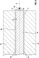
- FIG. 5 shows a section through the tubular element 60 FIG. 3 with closed base.
- connection of the end regions of the front sides 33, 34 of the tubular element 60 takes place, for example, by means of a roll seam weld, wherein a transverse weld seam 68 is introduced into the fold 64.
- the transverse weld 68 runs perpendicular to the front sides 33, 34 and at right angles to the longitudinal axis A.
- the closed first base of the tubular element 60 then forms a bottom 31 of a cell housing 3. This results in the cup-like or pot-shaped, cuboid cell housing 3, which is made of the tubular element 60 and one piece is designed.
- the transverse weld seam 68 extends along the bottom 31 of the cell housing 3.
- the fold 64 is at right angles from the first base of the tubular element 60, or from the bottom 31 of the cell case 3, from.
- the fold is then bent by 90 ° and is thus parallel to the bottom 31 at the bottom 31 at.
- the two pockets are initially in opposite directions from the cell case 3 from.
- the two pockets are then bent by 180 ° and thus folded onto the bottom 31 of the cell case 3. From the food industry packaging, especially for drinks, are known, which are folded in a similar manner.
- an electrode unit is subsequently introduced into the cell housing 3. Subsequently, a second base surface of the tubular element 60 lying opposite the first base surface is also closed. The second base of the tubular element 60 is in this case closed by means of a flat lid 32. Thus, the cell case 3 is completely closed and the electrode unit is surrounded by the cell case 3.
- a present liquid electrolyte is also filled, which then surrounds the electrode unit within the cell housing 3.
- the liquid electrolyte can be filled in, for example, before applying the lid 32.
- the electrolyte can be filled even after application of the lid 32 through an opening, which is provided for example in the lid 32 become. The said opening is then closed after filling the electrolyte.
- FIG. 6 shows a partially transparent perspective view of a battery cell 2 with the cuboid-shaped cell housing 3.
- the cell housing 3 of the battery cell 2 has six sides with three different sized surfaces, each with two sides with the same area are opposite to each other.
- the pages with the largest area contents are the first front page 33 and the second front page 34.
- the pages with the smallest area contents are the first face 35 and the second face 36.
- the remaining pages with the medium area contents are the bottom 31 and the lid 32.
- the battery cell 2 comprises a negative terminal 11 and a positive terminal 12. A voltage supplied by the battery cell 2 can be tapped off via the two terminals 11, 12. Furthermore, the battery cell 2 can also be charged via the two terminals 11, 12.
- the two terminals 11, 12 are arranged spaced from each other on the lid 32. In the present case, the negative terminal 11 is adjacent to the first end face 35, and the positive terminal 12 is adjacent to the second end face 36.
- the terminals 11, 12 are electrically connected to the electrode unit 10, which is not shown here.
- the cuboid cell housing 3 has eight edges. Adjacent to the first front side 33 of the cell housing 3 four edges, which are referred to as first front edges 51. Adjacent to the second front side 34 of the cell housing 3 four edges, which are referred to as second front edges 52.
- the cuboid cell housing 3 has four further edges, which adjoin one of the two end faces 35, 36 and the bottom 31 as well as the lid 32.
- a first longitudinal edge 41 adjoins the lid 32 and the first end face 35.
- a second longitudinal edge 42 adjoins the bottom 31 and the first end face 35.
- a third longitudinal edge 43 adjoins the lid 32 and the second end face 36 at.
- a fourth longitudinal edge 44 adjoins the bottom 31 and the second end face 36.
- the two pockets which were previously bent by 180 ° and thus folded onto the bottom 31 of the cell case 3, are located on the second longitudinal edge 42 and on the fourth longitudinal edge 44.
- the said pockets are, as well as the fold 64 in this illustration not shown.
Landscapes
- Chemical & Material Sciences (AREA)
- Chemical Kinetics & Catalysis (AREA)
- Electrochemistry (AREA)
- General Chemical & Material Sciences (AREA)
- Inorganic Chemistry (AREA)
- Engineering & Computer Science (AREA)
- Mechanical Engineering (AREA)
- Sealing Battery Cases Or Jackets (AREA)
Abstract
Description
- Die Erfindung betrifft ein Verfahren zur Herstellung eines Zellengehäuses für eine Batteriezelle aus einem Rohrelement. Die Erfindung betrifft auch eine Batteriezelle, welche ein Zellengehäuse umfasst, welches mittels des erfindungsgemäßen Verfahrens hergestellt ist.
- Batteriezellen, insbesondere Lithium-Ionen-Zellen und Lithium-Festkörperzellen weisen häufig ein prismatisches oder quaderförmiges Zellengehäuse auf. Dabei werden mehrere Batteriezellen in einem Batteriemodul räumlich nebeneinander angeordnet und elektrisch seriell miteinander verschaltet. Insbesondere quaderförmige Zellengehäuse können räumlich dicht nebeneinander angeordnet werden, ohne dass ungenutzte Freiräume zwischen benachbarten Batteriezellen entstehen.
- Zellengehäuse für Batteriezellen sind beispielsweise aus einem Metall, insbesondere aus Aluminium, gefertigt. Zur Vermeidung von Kurzschlüssen zwischen benachbarten Batteriezellen innerhalb eines Batteriemoduls und zur Verhinderung von einer elektrischen Spannung auf angrenzenden Teilen des Batteriemoduls können die metallischen Zellengehäuse außen elektrisch isoliert werden.
- Zellengehäuse für Batteriezellen werden beispielsweise durch Fließpressen, insbesondere Rückwärtsfließpressen, hergestellt. Dabei wird das insbesondere metallische Material zur Herstellung des Zellengehäuses mittels eines Stempels verformt. Eine spezielle Ausführungsform des Rückwärtsfließpressen ist das Napfrückwärtsfließpressen.
- Zellengehäuse für Batteriezellen können beispielsweise auch durch Tiefziehen hergestellt werden. Dabei wird das insbesondere metallische Material zur Herstellung des Zellengehäuses in einer Presse mittels eines geeigneten Werkzeugs verformt.
- Aus der
US 2009/0206096 A1 ist ein gattungsgemäßes Verfahren zur Herstellung eines prismatischen Gehäuses bekannt. Das derart hergestellte Gehäuse ist unter anderem als Zellengehäuse für eine Batteriezelle verwendbar. Dabei wird zunächst ein Rohrelement mit einem kreisförmigen Querschnitt derart verformt, dass ein rechteckförmiger Querschnitt entsteht. Anschließend werden die Grundflächen des Rohrelements mit einen Bodenelement sowie mit einem Deckelelement verschlossen. Es entsteht somit ein dreiteilig ausgebildetes Gehäuse. - Es wird ein Verfahren zur Herstellung eines insbesondere prismatischen Zellengehäuses für eine Batteriezelle vorgeschlagen. Das Verfahren umfasst die nachfolgend genannten Schritte
- Zunächst wird ein Rohrelement mit einem zumindest annähernd kreisförmigen Querschnitt bereitgestellt. Das besagte Rohrelement weist beispielsweise die Form eines Hohlzylinders auf und ist rotationssymmetrisch zu einer Längsachse ausgebildet. Das Rohrelement kann auch einen anderen Querschnitt aufweisen, beispielsweise oval oder rechteckig, sollte aber entlang der Längsachse einen gleichbleibenden Querschnitt aufweisen. Eine der Längsachse zugewandte Seite des Rohrelements wird im Folgenden als Innenseite bezeichnet. Eine gegenüberliegende, der Längsachse abgewandte Seite des Rohrelements wird im Folgenden als Außenseite bezeichnet.
- Anschließend folgt das Anlegen von zwei Dornen an diametral gegenüberliegende Bereiche an der Innenseite des Rohrelements. Die Dorne sind dabei vorzugsweise quaderförmig ausgebildet und erstrecken sich entlang der Längsachse zumindest annähernd über die gesamte Länge des Rohrelements.
- Anschließend werden die zwei Dorne voneinander weg bewegt. Dadurch wird das Rohrelement verformt und erhält einen zumindest annähernd rechteckförmigen Querschnitt mit einer ersten Frontseite, einer gegenüberliegenden zweiten Frontseite, einer ersten Stirnseite und einer gegenüberliegenden zweiten Stirnseite.
- Die Dorne liegen dabei an den beiden Stirnseiten des Rohrelements an. Die Stirnseiten haben eine geringere Ausdehnung als die Frontseiten. Zwischen den beiden Dornen und zentralen Bereichen der beiden Frontseiten entsteht zunächst ein Hohlraum.
- Anschließend erfolgt ein Verschließen einer ersten Grundfläche des Rohrelements. Die erste Grundfläche steht dabei rechtwinklig zu den beiden Stirnseiten und rechtwinklig zu den beiden Frontseiten. Die verschlossene erste Grundfläche bildet dann einen Boden des Zellengehäuses.
- Es entsteht somit ein becherartig oder topfartig ausgebildetes, quaderförmiges Zellengehäuse, welches einteilig ausgestaltet ist. Das bedeutet, das Zellengehäuse ist aus einem einzigen Rohrelement hergestellt. Zur Fertigung einer Batteriezelle wird anschließend eine Elektrodeneinheit in das Zellengehäuse eingeführt und eine der ersten Grundfläche gegenüberliegende zweite Grundfläche wird ebenfalls verschlossen.
- Gemäß einer vorteilhaften Ausgestaltung der Erfindung wird vor dem Verformen des Rohrelements an der Außenseite des Rohrelements gegenüber von jedem Dorn jeweils ein Klemmbacken angelegt. Das Rohrelement ist somit an zwei Stellen zwischen jeweils einem Dorn und einem Klemmbacken eingespannt und kraftschlüssig gehalten.
- Das Rohrelement kann beispielsweise durch Walzen hergestellt und nahtlos gefertigt sein. Das Rohrelement kann aber auch durch Verschweißen eines Blechs entlang einer Längsschweißnaht hergestellt sein, wobei die Längsschweißnaht gerade und parallel zu der Längsachse verläuft. In diesem Fall werden die beiden Dorne und die beiden Klemmbacken vorzugsweise derart angelegt, dass die Längsschweißnaht des Rohrelements sich zwischen einem Dorn und einem Klemmbacken befindet.
- Gemäß einer vorteilhaften Ausgestaltung der Erfindung wird nach dem Verformen des Rohrelements ein Füllstück zwischen die Dorne eingebracht. Das Füllstück wird dabei in den Hohlraum eingebracht, welcher zwischen den beiden Dornen und den zentralen Bereichen der beiden Frontseiten des Rohrelements entsteht. Das Füllstück weist einen rechteckförmigen Querschnitt auf und füllt den besagten Hohlraum zumindest annähernd vollständig aus.
- Gemäß einer vorteilhaften Weiterbildung der Erfindung wird nach dem Verformen des Rohrelements jeweils ein Prägebacken gegen die erste Frontseite und gegen die zweite Frontseite des Rohrelements gepresst. Die Frontseiten des Rohrelements sind somit zwischen den beiden Prägebacken und den beiden Dornen und gegebenenfalls auch zwischen den beiden Prägebacken und Füllstück eingespannt.
- Durch das Pressen der besagten Prägebacken beidseitig gegen die beiden Frontseiten des Rohrelements erfolgt eine Kalibrierung des rechteckförmigen Querschnitts des Rohrelements. Dadurch wird insbesondere eine Rückfederung des Rohrelements von dem rechteckförmigen Querschnitts in Richtung zu dem vorherigen Querschnitt minimiert.
- Gemäß einer bevorzugten Ausgestaltung der Erfindung werden zum Verschließen der ersten Grundfläche des Rohrelements Endbereiche der Frontseiten des Rohrelements mittels Schiebern gegeneinander gepresst. Anschließend werden die Endbereiche der Frontseiten miteinander verbunden und bilden den Boden des Zellengehäuses.
- Vorzugsweise werden die gegeneinander gepressten Endbereiche der beiden Frontseiten dabei miteinander stoffschlüssig verbunden, insbesondere verschweißt. Dadurch entsteht eine Querschweißnaht, welche sich entlang des Bodens des Zellengehäuses erstreckt.
- An dem Boden des Zellengehäuses bilden sich zwei dreieckförmige Taschen, welche zunächst in entgegengesetzte Richtungen von dem Zellengehäuse abstehen. Die beiden Taschen werden dann um 180° gebogen und somit auf den Boden des Zellengehäuses geklappt. Aus der Lebensmittelindustrie sind Verpackungen, insbesondere für Getränke, bekannt, welche auf ähnliche Art gefaltet werden.
- Gemäß einer bevorzugten Weiterbildung der Erfindung wird bei der Fertigung der Batteriezelle eine der ersten Grundfläche gegenüberliegende zweite Grundfläche des Rohrelements mittels eines Deckels verschlossen. Somit ist das Zellengehäuse rundum geschlossen.
- Gemäß einer vorteilhaften Ausgestaltung der Erfindung wird das Rohrelement derart verformt, dass eine Wandstärke des Rohrelements dabei verringert wird. Das Rohrelement wird also in Richtung senkrecht zu der Längsachse gedehnt, wodurch die Wandstärke verringert wird.
- Es wird auch eine Batteriezelle vorgeschlagen, die ein Zellengehäuse umfasst, welches mittels des erfindungsgemäßen Verfahrens hergestellt ist. Die Batteriezelle ist beispielsweise eine Lithium-Ionen-Zelle.
- Mittels des erfindungsgemäßen Verfahrens sind Zellengehäuse für Batteriezellen kostengünstig herstellbar. Das erfindungsgemäße Verfahren gestattet darüber hinaus die Herstellung von Zellengehäusen mit verhältnismäßig geringen Wandstärken sowie mit kleinen Kantenradien. Das erfindungsgemäße Verfahren benötigt keinen Stempel im konventionellen Sinn zur Verformung des Rohrelements. Somit sind Zellengehäuse mit verhältnismäßig großer Länge herstellbar, welche aufgrund einer zu geringen Knicksteifigkeit des Stempels mit konventionellen Umformverfahren nicht herstellbar sind. Die geometrischen Abmessungen des herzustellenden Zellengehäuses sind somit annähernd frei wählbar. Auch können Zellengehäuse aus beschichteten Blechen hergestellt werden.
- Ausführungsformen der Erfindung werden anhand der Zeichnungen und der nachfolgenden Beschreibung näher erläutert.
- Es zeigen:
- Figur 1
- eine perspektivische Darstellung eines Rohrelements mit kreisförmigem Querschnitt,
- Figur 2
- eine Draufsicht auf das Rohrelement aus
Figur 1 unmittelbar vor dem Verformen, - Figur 3
- eine Draufsicht auf das Rohrelement aus
Figur 2 nach dem Verformen mit rechteckförmigem Querschnitt, - Figur 4
- einen Schnitt durch das Rohrelement aus
Figur 3 beim Verschließen einer Grundfläche, - Figur 5
- einen Schnitt durch das Rohrelement aus
Figur 3 mit verschlossener Grundfläche und - Figur 6
- eine teiltransparente perspektivische Darstellung einer Batteriezelle.
- In der nachfolgenden Beschreibung der Ausführungsformen der Erfindung werden gleiche oder ähnliche Elemente mit gleichen Bezugszeichen bezeichnet, wobei auf eine wiederholte Beschreibung dieser Elemente in Einzelfällen verzichtet wird. Die Figuren stellen den Gegenstand der Erfindung nur schematisch dar.
-
Figur 1 zeigt eine perspektivische Darstellung eines Rohrelements 60 mit einem kreisförmigen Querschnitt. Das Rohrelement 60 ist vorliegend in Form eines Hohlzylinders ausgebildet und ist rotationssymmetrisch zu einer Längsachse A. - Das Rohrelement 60 weist eine der Längsachse A zugewandte Innenseite 61 und eine gegenüberliegende, der Längsachse A abgewandte Außenseite 62 auf. Das Rohrelement 60 weist eine Wandstärke D auf. Ferner ist das Rohrelement 60 entlang einer Längsschweißnaht 66 welche gerade und parallel zu der Längsachse A verläuft, geschweißt.
-
Figur 2 zeigt eine Draufsicht auf das Rohrelement 60 ausFigur 1 unmittelbar vor dem Verformen. An diametral gegenüberliegenden Bereichen an der Innenseite 61 des Rohrelements 60 sind zwei Dorne 70 angelegt. Die Dorne 70 sind dabei quaderförmig ausgebildet und erstrecken sich entlang der Längsachse A annähernd über die gesamte Länge des Rohrelements 60. - An der Außenseite 62 des Rohrelements 60 ist gegenüber von jedem Dorn 70 jeweils ein Klemmbacken 72 angelegt. Das Rohrelement 60 ist somit an zwei Stellen zwischen jeweils einem Dorn 70 und einem Klemmbacken 72 eingespannt und kraftschlüssig gehalten. Die Längsschweißnaht 66 des Rohrelements 60 befindet sich dabei zwischen einem Dorn 70 und einem Klemmbacken 72.
-
Figur 3 zeigt eine Draufsicht auf das Rohrelement 60 ausFigur 2 nach dem Verformen mit einem rechteckförmigen Querschnitt. Das Rohrelement 60 wird dadurch verformt, dass die zwei Dorne 70 voneinander weg bewegt werden. Das Rohrelement 60 erhält somit den rechteckförmigen Querschnitt mit einer ersten Frontseite 33, einer gegenüberliegenden zweiten Frontseite 34, einer ersten Stirnseite 35 und einer gegenüberliegenden zweiten Stirnseite 36. Die Dorne 70 liegen dabei an den beiden Stirnseiten 35, 36 des Rohrelements 60 an, welche eine geringere Ausdehnung haben als die beiden Frontseiten 33, 34. Die Längsschweißnaht 66 des Rohrelements befindet sich vorliegend an der zweiten Stirnseite 36. - In einen zwischen den beiden Dornen 70 und zentralen Bereichen der beiden Frontseiten 33, 34 entstandenen Hohlraum ist ein Füllstück 74 eingebracht. Das Füllstück 74 weist ebenfalls einen rechteckförmigen Querschnitt auf und füllt den besagten Hohlraum vollständig aus. Gegen die erste Frontseite 33 und gegen die zweite Frontseite 34 des Rohrelements 60 wird jeweils ein Prägebacken 76 gepresst. Die Frontseiten 33, 34 des Rohrelements 60 sind somit zwischen den beiden Prägebacken 76 und den beiden Dornen 70 sowie zwischen den beiden Prägebacken 76 und Füllstück 74 eingespannt.
-
Figur 4 zeigt einen Schnitt durch das Rohrelement 60 entlang der Schnittlinie S ausFigur 3 beim Verschließen einer ersten Grundfläche des Rohrelements 60. Die erste Grundfläche des Rohrelements 60 steht dabei rechtwinklig zu den beiden Stirnseiten 35, 36 und rechtwinklig zu den beiden Frontseiten 33, 34. Die Längsachse A des Rohrelements 60 steht ebenfalls rechtwinklig zu der ersten Grundfläche. - Endbereiche des Rohrelements 60 ragen in Richtung der Längsachse A über die Dorne 70, über die Prägebacken 76 und über das in dieser Darstellung verdeckte Füllstück 74 hinaus. Zum Verschließen der ersten Grundfläche des Rohrelements 60 werden die Endbereiche der Frontseiten 33, 34 des Rohrelements 60 mittels Schiebern 78 gegeneinander gepresst. Die Bewegung der Schieber 78 erfolgt dabei in Richtung aufeinander zu und rechtwinklig zu der Längsachse A.
- Durch die besagte Bewegung der Schieber 78 wird aus den Endbereichen der Frontseiten 33, 34 des Rohrelements 60 ein Falz 64 gebildet, welcher rechtwinklig von der ersten Grundfläche des Rohrelements 60 absteht. Der entstandene Falz 64 wird dabei in der hier gezeigten Darstellung kraftschlüssig von den Schiebern 78 gehalten.
- Anschließend werden die gegeneinander gepressten Endbereiche der Frontseiten 33, 34 des Rohrelements 60, welche den Falz 64 bilden, miteinander stoffschlüssig verbunden, insbesondere verschweißt. Durch diese Verbindung der Endbereiche der Frontseiten 33, 34 des Rohrelements 60 miteinander wird die erste Grundfläche des Rohrelements 60 verschlossen.
Figur 5 zeigt einen Schnitt durch das Rohrelement 60 ausFigur 3 mit verschlossener Grundfläche. - Die Verbindung der Endbereiche der Frontseiten 33, 34 des Rohrelements 60 geschieht beispielsweise mittels einer Rollnahtschweißung, wobei in den Falz 64 eine Querschweißnaht 68 eingebracht wird. Die Querschweißnaht 68 verläuft rechtwinklig zu den Frontseiten 33, 34 und rechtwinklig zu der Längsachse A. Die verschlossene erste Grundfläche des Rohrelements 60 bildet dann einen Boden 31 eines Zellengehäuses 3. Dadurch entsteht das becherartig oder topfartig ausgebildete, quaderförmige Zellengehäuse 3, welches aus dem Rohrelement 60 hergestellt und einteilig ausgestaltet ist. Die Querschweißnaht 68 erstreckt sich entlang des Bodens 31 des Zellengehäuses 3.
- Nach der Verbindung der Endbereiche der Frontseiten 33, 34 des Rohrelements 60, also nach dem Einbringen der Querschweißnaht 68 in den Falz 64, steht der Falz 64 rechtwinklig von der ersten Grundfläche des Rohrelements 60, beziehungsweise von dem Boden 31 des Zellengehäuses 3, ab. Der Falz wird dann um 90° gebogen und liegt damit parallel zu dem Boden 31 an dem Boden 31 an.
- Dadurch bilden sich zwei dreieckförmige Taschen, durch welche der Falz 64 hindurch verläuft. Die beiden Taschen stehen zunächst in entgegengesetzte Richtungen von dem Zellengehäuse 3 ab. Die beiden Taschen werden dann um 180° gebogen und somit auf den Boden 31 des Zellengehäuses 3 geklappt. Aus der Lebensmittelindustrie sind Verpackungen, insbesondere für Getränke, bekannt, welche auf ähnliche Art gefaltet werden.
- Zur Fertigung einer Batteriezelle 2 wird anschließend eine Elektrodeneinheit in das Zellengehäuse 3 eingeführt. Anschließend wird eine der ersten Grundfläche gegenüberliegende zweite Grundfläche des Rohrelements 60 ebenfalls verschlossen. Die zweite Grundfläche des Rohrelements 60 wird dabei vorliegend mittels eines flachen Deckels 32 verschlossen. Somit ist das Zellengehäuse 3 rundum geschlossen und die Elektrodeneinheit ist von dem Zellengehäuse 3 umgeben.
- In das Zellengehäuse 3 wird auch ein vorliegend flüssiger Elektrolyt eingefüllt, welcher dann die Elektrodeneinheit innerhalb des Zellengehäuses 3 umgibt. Der flüssige Elektrolyt kann beispielsweise vor Aufbringen des Deckels 32 eingefüllt werden. Der Elektrolyt kann auch nach Aufbringen des Deckels 32 durch eine Öffnung, welche beispielsweise in dem Deckel 32 vorgesehen ist, eingefüllt werden. Die besagte Öffnung wird dann nach dem Einfüllen des Elektrolyten verschlossen.
-
Figur 6 zeigt eine teiltransparente perspektivische Darstellung einer Batteriezelle 2 mit dem quaderförmig ausgebildeten Zellengehäuse 3. Das Zellengehäuse 3 der Batteriezelle 2 weist sechs Seiten mit drei verschieden großen Flächeninhalten auf, wobei jeweils zwei Seiten mit gleich großen Flächeninhalten einander gegenüber liegen. Die Seiten mit den größten Flächeninhalten sind die erste Frontseite 33 und die zweite Frontseite 34. Die Seiten mit den kleinsten Flächeninhalten sind die erste Stirnseite 35 und zweite Stirnseite 36. Die verbleibenden Seiten mit den mittelgroßen Flächeninhalten sind der Boden 31 und der Deckel 32. - Die Batteriezelle 2 umfasst ein negatives Terminal 11 und ein positives Terminal 12. Über die beiden Terminals 11, 12 kann eine von der Batteriezelle 2 zur Verfügung gestellte Spannung abgegriffen werden. Ferner kann die Batteriezelle 2 über die beiden Terminals 11, 12 auch geladen werden. Die beiden Terminals 11, 12 sind beabstandet voneinander an dem Deckel 32 angeordnet. Vorliegend befindet sich das negative Terminal 11 benachbart zu der ersten Stirnseite 35, und das positive Terminal 12 befindet sich benachbart zu der zweiten Stirnseite 36. Die Terminals 11, 12 sind elektrisch mit der Elektrodeneinheit 10 verbunden, die hier nicht dargestellt ist.
- Das quaderförmige Zellengehäuse 3 weist acht Kanten auf. An die erste Frontseite 33 des Zellengehäuses 3 grenzende vier Kanten an, welche als erste Frontkanten 51 bezeichnet werden. An die zweite Frontseite 34 des Zellengehäuses 3 grenzende vier Kanten an, welche als zweite Frontkanten 52 bezeichnet werden.
- Das quaderförmige Zellengehäuse 3 weist vier weitere Kanten auf, welche an je eine der beiden Stirnseiten 35, 36 und an den Boden 31 sowie an den Deckel 32 angrenzen. Dabei grenzt eine erste Längskante 41 an den Deckel 32 und an die erste Stirnseite 35 an. Eine zweite Längskante 42 grenzt an den Boden 31 und an die erste Stirnseite 35 an. Eine dritte Längskante 43 grenzt an den Deckel 32 und die an zweite Stirnseite 36 an. Eine vierte Längskante 44 grenzt an den Boden 31 und an die zweite Stirnseite 36 an.
- Die beiden Taschen, welche zuvor um 180° gebogen und somit auf den Boden 31 des Zellengehäuses 3 geklappt wurden, befinden sich an der zweiten Längskante 42 sowie an der vierten Längskante 44. Die besagten Taschen sind, ebenso wie der Falz 64 in dieser Darstellung nicht gezeigt.
- Die Erfindung ist nicht auf die hier beschriebenen Ausführungsbeispiele und die darin hervorgehobenen Aspekte beschränkt. Vielmehr ist innerhalb des durch die Ansprüche angegebenen Bereichs eine Vielzahl von Abwandlungen möglich, die im Rahmen fachmännischen Handelns liegen.
Claims (10)
- Verfahren zur Herstellung eines Zellengehäuses (3) für eine Batteriezelle (2), umfassend folgende Schritte:Bereitstellen eines Rohrelements (60) mit einem zumindest annähernd kreisförmigen Querschnitt;Anlegen von zwei Dornen (70) an diametral gegenüberliegende Bereiche an einer Innenseite (61) des Rohrelements (60);Voneinander weg Bewegen der zwei Dorne (70), wodurch das Rohrelement (60) verformt wird und einen zumindest annähernd rechteckförmigen Querschnitt mit einer ersten Frontseite (33), einer gegenüberliegenden zweiten Frontseite (34), einer ersten Stirnseite (35) und einer gegenüberliegenden zweiten Stirnseite (36) erhält;Verschließen einer ersten Grundfläche des Rohrelements (60).
- Verfahren nach Anspruch 1, wobei
vor dem Verformen des Rohrelements (60) an einer Außenseite (62) des Rohrelements (60) gegenüber von jedem Dorn (70) jeweils ein Klemmbacken (72) angelegt wird. - Verfahren nach Anspruch 2, wobei
die Dorne (70) und die Klemmbacken (72) derart angelegt werden, dass eine Längsschweißnaht (66) des Rohrelements (60) sich zwischen einem Dorn (70) und einem Klemmbacken (72) befindet. - Verfahren nach einem der vorstehenden Ansprüche, wobei nach dem Verformen des Rohrelements (60) ein Füllstück (74) zwischen die Dorne (70) eingebracht wird.
- Verfahren nach einem der vorstehenden Ansprüche, wobei nach dem Verformen des Rohrelements (60) jeweils ein Prägebacken (76) gegen die erste Frontseite (33) und gegen die zweite Frontseite (34) gepresst wird.
- Verfahren nach einem der vorstehenden Ansprüche, wobei zum Verschließen der ersten Grundfläche des Rohrelements (60) Endbereiche der Frontseiten (33, 34) mittels Schiebern (78) gegeneinander gepresst werden.
- Verfahren nach Anspruch 6, wobei
die gegeneinander gepressten Endbereiche der Frontseiten (33, 34) miteinander stoffschlüssig verbunden werden. - Verfahren nach einem der vorstehenden Ansprüche, wobei eine der ersten Grundfläche gegenüberliegende zweite Grundfläche des Rohrelements (60) mittels eines Deckels (32) verschlossen wird.
- Verfahren nach einem der vorstehenden Ansprüche, wobei das Rohrelement (60) derart verformt wird, dass eine Wandstärke (D) des Rohrelements (60) verringert wird.
- Batteriezelle (2), umfassend ein Zellengehäuse (3), welches mittels des Verfahrens nach einem der vorstehenden Ansprüche hergestellt ist.
Applications Claiming Priority (1)
| Application Number | Priority Date | Filing Date | Title |
|---|---|---|---|
| DE102017220115.0A DE102017220115A1 (de) | 2017-11-13 | 2017-11-13 | Verfahren zur Herstellung eines Zellengehäuses für eine Batteriezelle und Batteriezelle |
Publications (2)
| Publication Number | Publication Date |
|---|---|
| EP3486966A1 true EP3486966A1 (de) | 2019-05-22 |
| EP3486966B1 EP3486966B1 (de) | 2020-12-09 |
Family
ID=63798862
Family Applications (1)
| Application Number | Title | Priority Date | Filing Date |
|---|---|---|---|
| EP18199228.0A Active EP3486966B1 (de) | 2017-11-13 | 2018-10-09 | Verfahren zur herstellung eines zellengehäuses für eine batteriezelle und batteriezelle |
Country Status (3)
| Country | Link |
|---|---|
| EP (1) | EP3486966B1 (de) |
| CN (1) | CN109773074A (de) |
| DE (1) | DE102017220115A1 (de) |
Cited By (3)
| Publication number | Priority date | Publication date | Assignee | Title |
|---|---|---|---|---|
| DE102022115353A1 (de) | 2022-06-21 | 2023-12-21 | Volkswagen Aktiengesellschaft | Batterie mit Gehäusemantel in Form eines Biegebauteils |
| JP2023554507A (ja) * | 2021-05-26 | 2023-12-27 | 恵州億緯▲リ▼能股▲フン▼有限公司 | 電池ケースおよびリチウム電池 |
| DE102024102121A1 (de) * | 2024-01-25 | 2025-07-31 | Schaeffler Technologies AG & Co. KG | Verfahren zum Herstellen eines Gehäuses einer Batteriezelle, Gehäuse einer Batteriezelle, Batterie und Verwendung der Batterie |
Citations (3)
| Publication number | Priority date | Publication date | Assignee | Title |
|---|---|---|---|---|
| JP2003208876A (ja) * | 2000-12-26 | 2003-07-25 | Matsushita Electric Ind Co Ltd | 角形電池缶およびその製造方法並びにそれを用いた角形電池 |
| EP1886740A1 (de) * | 2005-05-17 | 2008-02-13 | Toyo Seikan Kaisha, Ltd. | Dreiteilige quadratische dose und herstellungsverfahren dafür |
| US20110300423A1 (en) * | 2010-06-03 | 2011-12-08 | Samsung Sdi Co., Ltd. | Rechargeable battery |
Family Cites Families (9)
| Publication number | Priority date | Publication date | Assignee | Title |
|---|---|---|---|---|
| CN1121726C (zh) * | 2000-01-22 | 2003-09-17 | 深圳市华粤宝电池有限公司 | 电池外壳的制造方法 |
| JP4020580B2 (ja) * | 2000-10-13 | 2007-12-12 | 松下電器産業株式会社 | 偏平角形電池 |
| US6946221B2 (en) * | 2000-12-26 | 2005-09-20 | Matsushita Electric Industrial Co., Ltd. | Square battery container, method of manufacturing the container, and square battery using the container |
| KR20060034508A (ko) * | 2004-10-19 | 2006-04-24 | 삼성에스디아이 주식회사 | 파우치형 이차 전지 |
| JP2006320914A (ja) * | 2005-05-17 | 2006-11-30 | Toyo Seikan Kaisha Ltd | 角缶のネッキング方法およびその装置 |
| DE102006049146B4 (de) * | 2006-10-17 | 2012-12-27 | Braun CarTec GmbH | Verfahren zur Herstellung einer aus mindestens zwei miteinander verbundenen Blechteilen bestehenden Baugruppe |
| JP5355883B2 (ja) * | 2007-12-13 | 2013-11-27 | 新日鐵住金株式会社 | キャニング性に優れたプレス成形方法 |
| KR20160045468A (ko) * | 2014-10-17 | 2016-04-27 | 주식회사 엘지화학 | 파우치형 이차 전지 및 그의 제조방법 |
| JP6986827B2 (ja) * | 2015-02-12 | 2021-12-22 | 株式会社半導体エネルギー研究所 | 蓄電装置及び電子機器 |
-
2017
- 2017-11-13 DE DE102017220115.0A patent/DE102017220115A1/de not_active Withdrawn
-
2018
- 2018-10-09 EP EP18199228.0A patent/EP3486966B1/de active Active
- 2018-11-12 CN CN201811339274.8A patent/CN109773074A/zh active Pending
Patent Citations (4)
| Publication number | Priority date | Publication date | Assignee | Title |
|---|---|---|---|---|
| JP2003208876A (ja) * | 2000-12-26 | 2003-07-25 | Matsushita Electric Ind Co Ltd | 角形電池缶およびその製造方法並びにそれを用いた角形電池 |
| EP1886740A1 (de) * | 2005-05-17 | 2008-02-13 | Toyo Seikan Kaisha, Ltd. | Dreiteilige quadratische dose und herstellungsverfahren dafür |
| US20090206096A1 (en) | 2005-05-17 | 2009-08-20 | Toyo Seikan Kaisha, Ltd. | Three-piece square can and method of manufacturing the same |
| US20110300423A1 (en) * | 2010-06-03 | 2011-12-08 | Samsung Sdi Co., Ltd. | Rechargeable battery |
Cited By (3)
| Publication number | Priority date | Publication date | Assignee | Title |
|---|---|---|---|---|
| JP2023554507A (ja) * | 2021-05-26 | 2023-12-27 | 恵州億緯▲リ▼能股▲フン▼有限公司 | 電池ケースおよびリチウム電池 |
| DE102022115353A1 (de) | 2022-06-21 | 2023-12-21 | Volkswagen Aktiengesellschaft | Batterie mit Gehäusemantel in Form eines Biegebauteils |
| DE102024102121A1 (de) * | 2024-01-25 | 2025-07-31 | Schaeffler Technologies AG & Co. KG | Verfahren zum Herstellen eines Gehäuses einer Batteriezelle, Gehäuse einer Batteriezelle, Batterie und Verwendung der Batterie |
Also Published As
| Publication number | Publication date |
|---|---|
| DE102017220115A1 (de) | 2019-05-16 |
| CN109773074A (zh) | 2019-05-21 |
| EP3486966B1 (de) | 2020-12-09 |
Similar Documents
| Publication | Publication Date | Title |
|---|---|---|
| DE102015111572A1 (de) | Batteriezellengehäuse und Verfahren zu dessen Herstellung | |
| DE102011086050A1 (de) | Batteriezelle, Batterie und Kraftfahrzeug | |
| EP3486966B1 (de) | Verfahren zur herstellung eines zellengehäuses für eine batteriezelle und batteriezelle | |
| DE102013201145A1 (de) | Energiespeicher-Element, Metallkomponente sowie Verfahren zum Herstellen eines Energiespeicher-Elementes | |
| DE112014001644T5 (de) | Elektrische Speichereinrichtung und elektrisches Speichergerät, welches mit der elektrischen Speichereinheit bereitgestellt ist | |
| WO2003079464A2 (de) | Becherförmiges gehäuse und kondensator mit dem gehäuse | |
| DE102015110244A1 (de) | Batteriezellengehäuse und Verfahren zu dessen Herstellung | |
| DE102005027679B4 (de) | Abdichtung, Verfahren zum Herstellen einer Crimp-Verbindung, Verfahren zum Herstellen eines Batteriegehäusedeckels und Verfahren zum Herstellen einer Batterie | |
| DE102016121089A1 (de) | Verfahren und Vorrichtung zur Herstellung eines prismatischen Batteriezellenbehälters | |
| DE102011122371A1 (de) | Elektrische Anschlusseinrichtung zur Herstellung einer Lötverbindung | |
| WO2014040791A1 (de) | Batteriezelle mit in gehäusedeckplatte integrierter berstscheibe | |
| DE10332093B4 (de) | Verfahren zur Herstellung einer elektrochemischen Zelle sowie die elektrochemische Zelle | |
| DE102009017276A1 (de) | Verfahren zum elektrohydraulischen Beschneiden, Bördeln und Falzen von Zuschnitten | |
| DE3538473A1 (de) | Metallbehaelter und verfahren zum falzen der enden | |
| EP3170574B1 (de) | Verfahren zur herstellung einer hülse für eine elektrode für medizinische anwendungen | |
| DE102016206848A1 (de) | Montagevorrichtung zum Anordnen eines Batteriezellmoduls, Montageanordnung sowie Verfahren zur Montage eines Batteriezellmoduls | |
| EP1654080A1 (de) | Verfahren zum innenhochdruckumformen von konischen rohren aus metall | |
| WO2015036525A1 (de) | Verfahren zur herstellung eines deckels mit verschluss | |
| DE102010062977A1 (de) | Umformwerkzeug mit Einrichtung zum elektromagnetischen Schneiden | |
| DE102019109460A1 (de) | Crimpkontakt | |
| DE102009037667A1 (de) | Verfahren zum verpacken von Produkten | |
| DE102019113152B3 (de) | Steckkontaktelement für eine elektrisch leitende Verbindung | |
| DE102007028317B3 (de) | Verfahren zum dauerhaften Verbinden eines ersten HF-Koaxialkabels mit einem zweiten HF-Koaxialkabel | |
| DE202011002790U1 (de) | Kontaktelement für einen Flachstecker, Kontaktelementestreifen und Flachstecker | |
| DE102020100102A1 (de) | Vorrichtung und Verfahren zur Herstellung eines dünnwandigen Bauteils |
Legal Events
| Date | Code | Title | Description |
|---|---|---|---|
| PUAI | Public reference made under article 153(3) epc to a published international application that has entered the european phase |
Free format text: ORIGINAL CODE: 0009012 |
|
| STAA | Information on the status of an ep patent application or granted ep patent |
Free format text: STATUS: THE APPLICATION HAS BEEN PUBLISHED |
|
| AK | Designated contracting states |
Kind code of ref document: A1 Designated state(s): AL AT BE BG CH CY CZ DE DK EE ES FI FR GB GR HR HU IE IS IT LI LT LU LV MC MK MT NL NO PL PT RO RS SE SI SK SM TR |
|
| AX | Request for extension of the european patent |
Extension state: BA ME |
|
| STAA | Information on the status of an ep patent application or granted ep patent |
Free format text: STATUS: REQUEST FOR EXAMINATION WAS MADE |
|
| 17P | Request for examination filed |
Effective date: 20191122 |
|
| RBV | Designated contracting states (corrected) |
Designated state(s): AL AT BE BG CH CY CZ DE DK EE ES FI FR GB GR HR HU IE IS IT LI LT LU LV MC MK MT NL NO PL PT RO RS SE SI SK SM TR |
|
| RAP1 | Party data changed (applicant data changed or rights of an application transferred) |
Owner name: ROBERT BOSCH GMBH |
|
| GRAP | Despatch of communication of intention to grant a patent |
Free format text: ORIGINAL CODE: EPIDOSNIGR1 |
|
| STAA | Information on the status of an ep patent application or granted ep patent |
Free format text: STATUS: GRANT OF PATENT IS INTENDED |
|
| INTG | Intention to grant announced |
Effective date: 20200603 |
|
| GRAS | Grant fee paid |
Free format text: ORIGINAL CODE: EPIDOSNIGR3 |
|
| GRAA | (expected) grant |
Free format text: ORIGINAL CODE: 0009210 |
|
| STAA | Information on the status of an ep patent application or granted ep patent |
Free format text: STATUS: THE PATENT HAS BEEN GRANTED |
|
| REG | Reference to a national code |
Ref country code: DE Ref legal event code: R079 Ref document number: 502018003246 Country of ref document: DE Free format text: PREVIOUS MAIN CLASS: H01M0002020000 Ipc: H01M0050100000 |
|
| AK | Designated contracting states |
Kind code of ref document: B1 Designated state(s): AL AT BE BG CH CY CZ DE DK EE ES FI FR GB GR HR HU IE IS IT LI LT LU LV MC MK MT NL NO PL PT RO RS SE SI SK SM TR |
|
| REG | Reference to a national code |
Ref country code: GB Ref legal event code: FG4D Free format text: NOT ENGLISH |
|
| REG | Reference to a national code |
Ref country code: AT Ref legal event code: REF Ref document number: 1344307 Country of ref document: AT Kind code of ref document: T Effective date: 20201215 Ref country code: CH Ref legal event code: EP |
|
| REG | Reference to a national code |
Ref country code: DE Ref legal event code: R096 Ref document number: 502018003246 Country of ref document: DE |
|
| REG | Reference to a national code |
Ref country code: IE Ref legal event code: FG4D Free format text: LANGUAGE OF EP DOCUMENT: GERMAN |
|
| PG25 | Lapsed in a contracting state [announced via postgrant information from national office to epo] |
Ref country code: GR Free format text: LAPSE BECAUSE OF FAILURE TO SUBMIT A TRANSLATION OF THE DESCRIPTION OR TO PAY THE FEE WITHIN THE PRESCRIBED TIME-LIMIT Effective date: 20210310 Ref country code: NO Free format text: LAPSE BECAUSE OF FAILURE TO SUBMIT A TRANSLATION OF THE DESCRIPTION OR TO PAY THE FEE WITHIN THE PRESCRIBED TIME-LIMIT Effective date: 20210309 Ref country code: FI Free format text: LAPSE BECAUSE OF FAILURE TO SUBMIT A TRANSLATION OF THE DESCRIPTION OR TO PAY THE FEE WITHIN THE PRESCRIBED TIME-LIMIT Effective date: 20201209 Ref country code: RS Free format text: LAPSE BECAUSE OF FAILURE TO SUBMIT A TRANSLATION OF THE DESCRIPTION OR TO PAY THE FEE WITHIN THE PRESCRIBED TIME-LIMIT Effective date: 20201209 |
|
| PG25 | Lapsed in a contracting state [announced via postgrant information from national office to epo] |
Ref country code: BG Free format text: LAPSE BECAUSE OF FAILURE TO SUBMIT A TRANSLATION OF THE DESCRIPTION OR TO PAY THE FEE WITHIN THE PRESCRIBED TIME-LIMIT Effective date: 20210309 Ref country code: LV Free format text: LAPSE BECAUSE OF FAILURE TO SUBMIT A TRANSLATION OF THE DESCRIPTION OR TO PAY THE FEE WITHIN THE PRESCRIBED TIME-LIMIT Effective date: 20201209 Ref country code: SE Free format text: LAPSE BECAUSE OF FAILURE TO SUBMIT A TRANSLATION OF THE DESCRIPTION OR TO PAY THE FEE WITHIN THE PRESCRIBED TIME-LIMIT Effective date: 20201209 |
|
| REG | Reference to a national code |
Ref country code: NL Ref legal event code: MP Effective date: 20201209 |
|
| PG25 | Lapsed in a contracting state [announced via postgrant information from national office to epo] |
Ref country code: NL Free format text: LAPSE BECAUSE OF FAILURE TO SUBMIT A TRANSLATION OF THE DESCRIPTION OR TO PAY THE FEE WITHIN THE PRESCRIBED TIME-LIMIT Effective date: 20201209 Ref country code: HR Free format text: LAPSE BECAUSE OF FAILURE TO SUBMIT A TRANSLATION OF THE DESCRIPTION OR TO PAY THE FEE WITHIN THE PRESCRIBED TIME-LIMIT Effective date: 20201209 |
|
| REG | Reference to a national code |
Ref country code: LT Ref legal event code: MG9D |
|
| PG25 | Lapsed in a contracting state [announced via postgrant information from national office to epo] |
Ref country code: LT Free format text: LAPSE BECAUSE OF FAILURE TO SUBMIT A TRANSLATION OF THE DESCRIPTION OR TO PAY THE FEE WITHIN THE PRESCRIBED TIME-LIMIT Effective date: 20201209 Ref country code: RO Free format text: LAPSE BECAUSE OF FAILURE TO SUBMIT A TRANSLATION OF THE DESCRIPTION OR TO PAY THE FEE WITHIN THE PRESCRIBED TIME-LIMIT Effective date: 20201209 Ref country code: SK Free format text: LAPSE BECAUSE OF FAILURE TO SUBMIT A TRANSLATION OF THE DESCRIPTION OR TO PAY THE FEE WITHIN THE PRESCRIBED TIME-LIMIT Effective date: 20201209 Ref country code: PT Free format text: LAPSE BECAUSE OF FAILURE TO SUBMIT A TRANSLATION OF THE DESCRIPTION OR TO PAY THE FEE WITHIN THE PRESCRIBED TIME-LIMIT Effective date: 20210409 Ref country code: SM Free format text: LAPSE BECAUSE OF FAILURE TO SUBMIT A TRANSLATION OF THE DESCRIPTION OR TO PAY THE FEE WITHIN THE PRESCRIBED TIME-LIMIT Effective date: 20201209 Ref country code: CZ Free format text: LAPSE BECAUSE OF FAILURE TO SUBMIT A TRANSLATION OF THE DESCRIPTION OR TO PAY THE FEE WITHIN THE PRESCRIBED TIME-LIMIT Effective date: 20201209 Ref country code: EE Free format text: LAPSE BECAUSE OF FAILURE TO SUBMIT A TRANSLATION OF THE DESCRIPTION OR TO PAY THE FEE WITHIN THE PRESCRIBED TIME-LIMIT Effective date: 20201209 |
|
| PG25 | Lapsed in a contracting state [announced via postgrant information from national office to epo] |
Ref country code: PL Free format text: LAPSE BECAUSE OF FAILURE TO SUBMIT A TRANSLATION OF THE DESCRIPTION OR TO PAY THE FEE WITHIN THE PRESCRIBED TIME-LIMIT Effective date: 20201209 |
|
| REG | Reference to a national code |
Ref country code: DE Ref legal event code: R097 Ref document number: 502018003246 Country of ref document: DE |
|
| PG25 | Lapsed in a contracting state [announced via postgrant information from national office to epo] |
Ref country code: IS Free format text: LAPSE BECAUSE OF FAILURE TO SUBMIT A TRANSLATION OF THE DESCRIPTION OR TO PAY THE FEE WITHIN THE PRESCRIBED TIME-LIMIT Effective date: 20210409 |
|
| PLBE | No opposition filed within time limit |
Free format text: ORIGINAL CODE: 0009261 |
|
| STAA | Information on the status of an ep patent application or granted ep patent |
Free format text: STATUS: NO OPPOSITION FILED WITHIN TIME LIMIT |
|
| PG25 | Lapsed in a contracting state [announced via postgrant information from national office to epo] |
Ref country code: AL Free format text: LAPSE BECAUSE OF FAILURE TO SUBMIT A TRANSLATION OF THE DESCRIPTION OR TO PAY THE FEE WITHIN THE PRESCRIBED TIME-LIMIT Effective date: 20201209 Ref country code: IT Free format text: LAPSE BECAUSE OF FAILURE TO SUBMIT A TRANSLATION OF THE DESCRIPTION OR TO PAY THE FEE WITHIN THE PRESCRIBED TIME-LIMIT Effective date: 20201209 |
|
| 26N | No opposition filed |
Effective date: 20210910 |
|
| PG25 | Lapsed in a contracting state [announced via postgrant information from national office to epo] |
Ref country code: DK Free format text: LAPSE BECAUSE OF FAILURE TO SUBMIT A TRANSLATION OF THE DESCRIPTION OR TO PAY THE FEE WITHIN THE PRESCRIBED TIME-LIMIT Effective date: 20201209 Ref country code: SI Free format text: LAPSE BECAUSE OF FAILURE TO SUBMIT A TRANSLATION OF THE DESCRIPTION OR TO PAY THE FEE WITHIN THE PRESCRIBED TIME-LIMIT Effective date: 20201209 |
|
| PG25 | Lapsed in a contracting state [announced via postgrant information from national office to epo] |
Ref country code: ES Free format text: LAPSE BECAUSE OF FAILURE TO SUBMIT A TRANSLATION OF THE DESCRIPTION OR TO PAY THE FEE WITHIN THE PRESCRIBED TIME-LIMIT Effective date: 20201209 |
|
| REG | Reference to a national code |
Ref country code: CH Ref legal event code: PL |
|
| PG25 | Lapsed in a contracting state [announced via postgrant information from national office to epo] |
Ref country code: IS Free format text: LAPSE BECAUSE OF FAILURE TO SUBMIT A TRANSLATION OF THE DESCRIPTION OR TO PAY THE FEE WITHIN THE PRESCRIBED TIME-LIMIT Effective date: 20210409 |
|
| REG | Reference to a national code |
Ref country code: BE Ref legal event code: MM Effective date: 20211031 |
|
| PG25 | Lapsed in a contracting state [announced via postgrant information from national office to epo] |
Ref country code: MC Free format text: LAPSE BECAUSE OF FAILURE TO SUBMIT A TRANSLATION OF THE DESCRIPTION OR TO PAY THE FEE WITHIN THE PRESCRIBED TIME-LIMIT Effective date: 20201209 |
|
| PG25 | Lapsed in a contracting state [announced via postgrant information from national office to epo] |
Ref country code: LU Free format text: LAPSE BECAUSE OF NON-PAYMENT OF DUE FEES Effective date: 20211009 Ref country code: BE Free format text: LAPSE BECAUSE OF NON-PAYMENT OF DUE FEES Effective date: 20211031 |
|
| PG25 | Lapsed in a contracting state [announced via postgrant information from national office to epo] |
Ref country code: LI Free format text: LAPSE BECAUSE OF NON-PAYMENT OF DUE FEES Effective date: 20211031 Ref country code: CH Free format text: LAPSE BECAUSE OF NON-PAYMENT OF DUE FEES Effective date: 20211031 |
|
| PG25 | Lapsed in a contracting state [announced via postgrant information from national office to epo] |
Ref country code: FR Free format text: LAPSE BECAUSE OF NON-PAYMENT OF DUE FEES Effective date: 20211031 |
|
| PG25 | Lapsed in a contracting state [announced via postgrant information from national office to epo] |
Ref country code: IE Free format text: LAPSE BECAUSE OF NON-PAYMENT OF DUE FEES Effective date: 20211009 |
|
| GBPC | Gb: european patent ceased through non-payment of renewal fee |
Effective date: 20221009 |
|
| PG25 | Lapsed in a contracting state [announced via postgrant information from national office to epo] |
Ref country code: CY Free format text: LAPSE BECAUSE OF FAILURE TO SUBMIT A TRANSLATION OF THE DESCRIPTION OR TO PAY THE FEE WITHIN THE PRESCRIBED TIME-LIMIT Effective date: 20201209 |
|
| PG25 | Lapsed in a contracting state [announced via postgrant information from national office to epo] |
Ref country code: HU Free format text: LAPSE BECAUSE OF FAILURE TO SUBMIT A TRANSLATION OF THE DESCRIPTION OR TO PAY THE FEE WITHIN THE PRESCRIBED TIME-LIMIT; INVALID AB INITIO Effective date: 20181009 |
|
| PG25 | Lapsed in a contracting state [announced via postgrant information from national office to epo] |
Ref country code: GB Free format text: LAPSE BECAUSE OF NON-PAYMENT OF DUE FEES Effective date: 20221009 |
|
| PG25 | Lapsed in a contracting state [announced via postgrant information from national office to epo] |
Ref country code: MK Free format text: LAPSE BECAUSE OF FAILURE TO SUBMIT A TRANSLATION OF THE DESCRIPTION OR TO PAY THE FEE WITHIN THE PRESCRIBED TIME-LIMIT Effective date: 20201209 |
|
| PG25 | Lapsed in a contracting state [announced via postgrant information from national office to epo] |
Ref country code: TR Free format text: LAPSE BECAUSE OF FAILURE TO SUBMIT A TRANSLATION OF THE DESCRIPTION OR TO PAY THE FEE WITHIN THE PRESCRIBED TIME-LIMIT Effective date: 20201209 |
|
| PG25 | Lapsed in a contracting state [announced via postgrant information from national office to epo] |
Ref country code: MT Free format text: LAPSE BECAUSE OF FAILURE TO SUBMIT A TRANSLATION OF THE DESCRIPTION OR TO PAY THE FEE WITHIN THE PRESCRIBED TIME-LIMIT Effective date: 20201209 |
|
| REG | Reference to a national code |
Ref country code: AT Ref legal event code: MM01 Ref document number: 1344307 Country of ref document: AT Kind code of ref document: T Effective date: 20231009 |
|
| PG25 | Lapsed in a contracting state [announced via postgrant information from national office to epo] |
Ref country code: AT Free format text: LAPSE BECAUSE OF NON-PAYMENT OF DUE FEES Effective date: 20231009 |
|
| PG25 | Lapsed in a contracting state [announced via postgrant information from national office to epo] |
Ref country code: AT Free format text: LAPSE BECAUSE OF NON-PAYMENT OF DUE FEES Effective date: 20231009 |
|
| PGFP | Annual fee paid to national office [announced via postgrant information from national office to epo] |
Ref country code: DE Payment date: 20251209 Year of fee payment: 8 |
|
| PGFP | Annual fee paid to national office [announced via postgrant information from national office to epo] |
Ref country code: AT Payment date: 20260410 Year of fee payment: 5 |