EP3486752A1 - Verfahren zur aktualisierung einer benutzerschnittstelle in einem computersystem - Google Patents
Verfahren zur aktualisierung einer benutzerschnittstelle in einem computersystem Download PDFInfo
- Publication number
- EP3486752A1 EP3486752A1 EP18205468.4A EP18205468A EP3486752A1 EP 3486752 A1 EP3486752 A1 EP 3486752A1 EP 18205468 A EP18205468 A EP 18205468A EP 3486752 A1 EP3486752 A1 EP 3486752A1
- Authority
- EP
- European Patent Office
- Prior art keywords
- user interface
- user
- computer system
- viewer
- region
- Prior art date
- Legal status (The legal status is an assumption and is not a legal conclusion. Google has not performed a legal analysis and makes no representation as to the accuracy of the status listed.)
- Granted
Links
Images







Classifications
-
- G—PHYSICS
- G06—COMPUTING OR CALCULATING; COUNTING
- G06F—ELECTRIC DIGITAL DATA PROCESSING
- G06F3/00—Input arrangements for transferring data to be processed into a form capable of being handled by the computer; Output arrangements for transferring data from processing unit to output unit, e.g. interface arrangements
- G06F3/01—Input arrangements or combined input and output arrangements for interaction between user and computer
- G06F3/011—Arrangements for interaction with the human body, e.g. for user immersion in virtual reality
- G06F3/013—Eye tracking input arrangements
-
- G—PHYSICS
- G02—OPTICS
- G02F—OPTICAL DEVICES OR ARRANGEMENTS FOR THE CONTROL OF LIGHT BY MODIFICATION OF THE OPTICAL PROPERTIES OF THE MEDIA OF THE ELEMENTS INVOLVED THEREIN; NON-LINEAR OPTICS; FREQUENCY-CHANGING OF LIGHT; OPTICAL LOGIC ELEMENTS; OPTICAL ANALOGUE/DIGITAL CONVERTERS
- G02F1/00—Devices or arrangements for the control of the intensity, colour, phase, polarisation or direction of light arriving from an independent light source, e.g. switching, gating or modulating; Non-linear optics
- G02F1/01—Devices or arrangements for the control of the intensity, colour, phase, polarisation or direction of light arriving from an independent light source, e.g. switching, gating or modulating; Non-linear optics for the control of the intensity, phase, polarisation or colour
- G02F1/13—Devices or arrangements for the control of the intensity, colour, phase, polarisation or direction of light arriving from an independent light source, e.g. switching, gating or modulating; Non-linear optics for the control of the intensity, phase, polarisation or colour based on liquid crystals, e.g. single liquid crystal display cells
- G02F1/137—Devices or arrangements for the control of the intensity, colour, phase, polarisation or direction of light arriving from an independent light source, e.g. switching, gating or modulating; Non-linear optics for the control of the intensity, phase, polarisation or colour based on liquid crystals, e.g. single liquid crystal display cells characterised by the electro-optical or magneto-optical effect, e.g. field-induced phase transition, orientation effect, guest-host interaction or dynamic scattering
- G02F1/139—Devices or arrangements for the control of the intensity, colour, phase, polarisation or direction of light arriving from an independent light source, e.g. switching, gating or modulating; Non-linear optics for the control of the intensity, phase, polarisation or colour based on liquid crystals, e.g. single liquid crystal display cells characterised by the electro-optical or magneto-optical effect, e.g. field-induced phase transition, orientation effect, guest-host interaction or dynamic scattering based on orientation effects in which the liquid crystal remains transparent
- G02F1/1393—Devices or arrangements for the control of the intensity, colour, phase, polarisation or direction of light arriving from an independent light source, e.g. switching, gating or modulating; Non-linear optics for the control of the intensity, phase, polarisation or colour based on liquid crystals, e.g. single liquid crystal display cells characterised by the electro-optical or magneto-optical effect, e.g. field-induced phase transition, orientation effect, guest-host interaction or dynamic scattering based on orientation effects in which the liquid crystal remains transparent the birefringence of the liquid crystal being electrically controlled, e.g. ECB-, DAP-, HAN-, PI-LC cells
-
- G—PHYSICS
- G02—OPTICS
- G02F—OPTICAL DEVICES OR ARRANGEMENTS FOR THE CONTROL OF LIGHT BY MODIFICATION OF THE OPTICAL PROPERTIES OF THE MEDIA OF THE ELEMENTS INVOLVED THEREIN; NON-LINEAR OPTICS; FREQUENCY-CHANGING OF LIGHT; OPTICAL LOGIC ELEMENTS; OPTICAL ANALOGUE/DIGITAL CONVERTERS
- G02F1/00—Devices or arrangements for the control of the intensity, colour, phase, polarisation or direction of light arriving from an independent light source, e.g. switching, gating or modulating; Non-linear optics
- G02F1/29—Devices or arrangements for the control of the intensity, colour, phase, polarisation or direction of light arriving from an independent light source, e.g. switching, gating or modulating; Non-linear optics for the control of the position or the direction of light beams, i.e. deflection
-
- G—PHYSICS
- G06—COMPUTING OR CALCULATING; COUNTING
- G06F—ELECTRIC DIGITAL DATA PROCESSING
- G06F18/00—Pattern recognition
- G06F18/20—Analysing
- G06F18/22—Matching criteria, e.g. proximity measures
-
- G—PHYSICS
- G06—COMPUTING OR CALCULATING; COUNTING
- G06F—ELECTRIC DIGITAL DATA PROCESSING
- G06F21/00—Security arrangements for protecting computers, components thereof, programs or data against unauthorised activity
- G06F21/30—Authentication, i.e. establishing the identity or authorisation of security principals
- G06F21/31—User authentication
- G06F21/32—User authentication using biometric data, e.g. fingerprints, iris scans or voiceprints
-
- G—PHYSICS
- G06—COMPUTING OR CALCULATING; COUNTING
- G06F—ELECTRIC DIGITAL DATA PROCESSING
- G06F21/00—Security arrangements for protecting computers, components thereof, programs or data against unauthorised activity
- G06F21/60—Protecting data
- G06F21/604—Tools and structures for managing or administering access control systems
-
- G—PHYSICS
- G06—COMPUTING OR CALCULATING; COUNTING
- G06F—ELECTRIC DIGITAL DATA PROCESSING
- G06F21/00—Security arrangements for protecting computers, components thereof, programs or data against unauthorised activity
- G06F21/60—Protecting data
- G06F21/606—Protecting data by securing the transmission between two devices or processes
-
- G—PHYSICS
- G06—COMPUTING OR CALCULATING; COUNTING
- G06F—ELECTRIC DIGITAL DATA PROCESSING
- G06F21/00—Security arrangements for protecting computers, components thereof, programs or data against unauthorised activity
- G06F21/60—Protecting data
- G06F21/62—Protecting access to data via a platform, e.g. using keys or access control rules
-
- G—PHYSICS
- G06—COMPUTING OR CALCULATING; COUNTING
- G06F—ELECTRIC DIGITAL DATA PROCESSING
- G06F21/00—Security arrangements for protecting computers, components thereof, programs or data against unauthorised activity
- G06F21/60—Protecting data
- G06F21/62—Protecting access to data via a platform, e.g. using keys or access control rules
- G06F21/6218—Protecting access to data via a platform, e.g. using keys or access control rules to a system of files or objects, e.g. local or distributed file system or database
-
- G—PHYSICS
- G06—COMPUTING OR CALCULATING; COUNTING
- G06F—ELECTRIC DIGITAL DATA PROCESSING
- G06F21/00—Security arrangements for protecting computers, components thereof, programs or data against unauthorised activity
- G06F21/60—Protecting data
- G06F21/62—Protecting access to data via a platform, e.g. using keys or access control rules
- G06F21/629—Protecting access to data via a platform, e.g. using keys or access control rules to features or functions of an application
-
- G—PHYSICS
- G06—COMPUTING OR CALCULATING; COUNTING
- G06F—ELECTRIC DIGITAL DATA PROCESSING
- G06F3/00—Input arrangements for transferring data to be processed into a form capable of being handled by the computer; Output arrangements for transferring data from processing unit to output unit, e.g. interface arrangements
- G06F3/01—Input arrangements or combined input and output arrangements for interaction between user and computer
- G06F3/017—Gesture based interaction, e.g. based on a set of recognized hand gestures
-
- G—PHYSICS
- G06—COMPUTING OR CALCULATING; COUNTING
- G06F—ELECTRIC DIGITAL DATA PROCESSING
- G06F3/00—Input arrangements for transferring data to be processed into a form capable of being handled by the computer; Output arrangements for transferring data from processing unit to output unit, e.g. interface arrangements
- G06F3/01—Input arrangements or combined input and output arrangements for interaction between user and computer
- G06F3/03—Arrangements for converting the position or the displacement of a member into a coded form
- G06F3/0304—Detection arrangements using opto-electronic means
-
- G—PHYSICS
- G06—COMPUTING OR CALCULATING; COUNTING
- G06F—ELECTRIC DIGITAL DATA PROCESSING
- G06F3/00—Input arrangements for transferring data to be processed into a form capable of being handled by the computer; Output arrangements for transferring data from processing unit to output unit, e.g. interface arrangements
- G06F3/01—Input arrangements or combined input and output arrangements for interaction between user and computer
- G06F3/048—Interaction techniques based on graphical user interfaces [GUI]
- G06F3/0481—Interaction techniques based on graphical user interfaces [GUI] based on specific properties of the displayed interaction object or a metaphor-based environment, e.g. interaction with desktop elements like windows or icons, or assisted by a cursor's changing behaviour or appearance
- G06F3/0482—Interaction with lists of selectable items, e.g. menus
-
- G—PHYSICS
- G06—COMPUTING OR CALCULATING; COUNTING
- G06F—ELECTRIC DIGITAL DATA PROCESSING
- G06F3/00—Input arrangements for transferring data to be processed into a form capable of being handled by the computer; Output arrangements for transferring data from processing unit to output unit, e.g. interface arrangements
- G06F3/01—Input arrangements or combined input and output arrangements for interaction between user and computer
- G06F3/048—Interaction techniques based on graphical user interfaces [GUI]
- G06F3/0481—Interaction techniques based on graphical user interfaces [GUI] based on specific properties of the displayed interaction object or a metaphor-based environment, e.g. interaction with desktop elements like windows or icons, or assisted by a cursor's changing behaviour or appearance
- G06F3/0483—Interaction with page-structured environments, e.g. book metaphor
-
- G—PHYSICS
- G06—COMPUTING OR CALCULATING; COUNTING
- G06F—ELECTRIC DIGITAL DATA PROCESSING
- G06F3/00—Input arrangements for transferring data to be processed into a form capable of being handled by the computer; Output arrangements for transferring data from processing unit to output unit, e.g. interface arrangements
- G06F3/01—Input arrangements or combined input and output arrangements for interaction between user and computer
- G06F3/048—Interaction techniques based on graphical user interfaces [GUI]
- G06F3/0484—Interaction techniques based on graphical user interfaces [GUI] for the control of specific functions or operations, e.g. selecting or manipulating an object, an image or a displayed text element, setting a parameter value or selecting a range
-
- G—PHYSICS
- G06—COMPUTING OR CALCULATING; COUNTING
- G06F—ELECTRIC DIGITAL DATA PROCESSING
- G06F3/00—Input arrangements for transferring data to be processed into a form capable of being handled by the computer; Output arrangements for transferring data from processing unit to output unit, e.g. interface arrangements
- G06F3/01—Input arrangements or combined input and output arrangements for interaction between user and computer
- G06F3/048—Interaction techniques based on graphical user interfaces [GUI]
- G06F3/0484—Interaction techniques based on graphical user interfaces [GUI] for the control of specific functions or operations, e.g. selecting or manipulating an object, an image or a displayed text element, setting a parameter value or selecting a range
- G06F3/04842—Selection of displayed objects or displayed text elements
-
- G—PHYSICS
- G06—COMPUTING OR CALCULATING; COUNTING
- G06F—ELECTRIC DIGITAL DATA PROCESSING
- G06F3/00—Input arrangements for transferring data to be processed into a form capable of being handled by the computer; Output arrangements for transferring data from processing unit to output unit, e.g. interface arrangements
- G06F3/01—Input arrangements or combined input and output arrangements for interaction between user and computer
- G06F3/048—Interaction techniques based on graphical user interfaces [GUI]
- G06F3/0484—Interaction techniques based on graphical user interfaces [GUI] for the control of specific functions or operations, e.g. selecting or manipulating an object, an image or a displayed text element, setting a parameter value or selecting a range
- G06F3/04845—Interaction techniques based on graphical user interfaces [GUI] for the control of specific functions or operations, e.g. selecting or manipulating an object, an image or a displayed text element, setting a parameter value or selecting a range for image manipulation, e.g. dragging, rotation, expansion or change of colour
-
- G—PHYSICS
- G06—COMPUTING OR CALCULATING; COUNTING
- G06F—ELECTRIC DIGITAL DATA PROCESSING
- G06F3/00—Input arrangements for transferring data to be processed into a form capable of being handled by the computer; Output arrangements for transferring data from processing unit to output unit, e.g. interface arrangements
- G06F3/01—Input arrangements or combined input and output arrangements for interaction between user and computer
- G06F3/048—Interaction techniques based on graphical user interfaces [GUI]
- G06F3/0484—Interaction techniques based on graphical user interfaces [GUI] for the control of specific functions or operations, e.g. selecting or manipulating an object, an image or a displayed text element, setting a parameter value or selecting a range
- G06F3/0485—Scrolling or panning
-
- G—PHYSICS
- G06—COMPUTING OR CALCULATING; COUNTING
- G06F—ELECTRIC DIGITAL DATA PROCESSING
- G06F3/00—Input arrangements for transferring data to be processed into a form capable of being handled by the computer; Output arrangements for transferring data from processing unit to output unit, e.g. interface arrangements
- G06F3/01—Input arrangements or combined input and output arrangements for interaction between user and computer
- G06F3/048—Interaction techniques based on graphical user interfaces [GUI]
- G06F3/0484—Interaction techniques based on graphical user interfaces [GUI] for the control of specific functions or operations, e.g. selecting or manipulating an object, an image or a displayed text element, setting a parameter value or selecting a range
- G06F3/0486—Drag-and-drop
-
- G—PHYSICS
- G06—COMPUTING OR CALCULATING; COUNTING
- G06F—ELECTRIC DIGITAL DATA PROCESSING
- G06F9/00—Arrangements for program control, e.g. control units
- G06F9/06—Arrangements for program control, e.g. control units using stored programs, i.e. using an internal store of processing equipment to receive or retain programs
- G06F9/44—Arrangements for executing specific programs
- G06F9/451—Execution arrangements for user interfaces
-
- G—PHYSICS
- G06—COMPUTING OR CALCULATING; COUNTING
- G06V—IMAGE OR VIDEO RECOGNITION OR UNDERSTANDING
- G06V40/00—Recognition of biometric, human-related or animal-related patterns in image or video data
- G06V40/10—Human or animal bodies, e.g. vehicle occupants or pedestrians; Body parts, e.g. hands
- G06V40/16—Human faces, e.g. facial parts, sketches or expressions
- G06V40/161—Detection; Localisation; Normalisation
-
- H—ELECTRICITY
- H04—ELECTRIC COMMUNICATION TECHNIQUE
- H04L—TRANSMISSION OF DIGITAL INFORMATION, e.g. TELEGRAPHIC COMMUNICATION
- H04L63/00—Network architectures or network communication protocols for network security
- H04L63/04—Network architectures or network communication protocols for network security for providing a confidential data exchange among entities communicating through data packet networks
- H04L63/0428—Network architectures or network communication protocols for network security for providing a confidential data exchange among entities communicating through data packet networks wherein the data content is protected, e.g. by encrypting or encapsulating the payload
-
- H—ELECTRICITY
- H04—ELECTRIC COMMUNICATION TECHNIQUE
- H04L—TRANSMISSION OF DIGITAL INFORMATION, e.g. TELEGRAPHIC COMMUNICATION
- H04L67/00—Network arrangements or protocols for supporting network services or applications
- H04L67/01—Protocols
- H04L67/06—Protocols specially adapted for file transfer, e.g. file transfer protocol [FTP]
-
- H—ELECTRICITY
- H04—ELECTRIC COMMUNICATION TECHNIQUE
- H04L—TRANSMISSION OF DIGITAL INFORMATION, e.g. TELEGRAPHIC COMMUNICATION
- H04L9/00—Cryptographic mechanisms or cryptographic arrangements for secret or secure communications; Network security protocols
- H04L9/08—Key distribution or management, e.g. generation, sharing or updating, of cryptographic keys or passwords
- H04L9/0861—Generation of secret information including derivation or calculation of cryptographic keys or passwords
- H04L9/0866—Generation of secret information including derivation or calculation of cryptographic keys or passwords involving user or device identifiers, e.g. serial number, physical or biometrical information, DNA, hand-signature or measurable physical characteristics
-
- G—PHYSICS
- G02—OPTICS
- G02B—OPTICAL ELEMENTS, SYSTEMS OR APPARATUS
- G02B27/00—Optical systems or apparatus not provided for by any of the groups G02B1/00 - G02B26/00, G02B30/00
- G02B27/01—Head-up displays
- G02B27/017—Head mounted
- G02B2027/0178—Eyeglass type
-
- G—PHYSICS
- G02—OPTICS
- G02F—OPTICAL DEVICES OR ARRANGEMENTS FOR THE CONTROL OF LIGHT BY MODIFICATION OF THE OPTICAL PROPERTIES OF THE MEDIA OF THE ELEMENTS INVOLVED THEREIN; NON-LINEAR OPTICS; FREQUENCY-CHANGING OF LIGHT; OPTICAL LOGIC ELEMENTS; OPTICAL ANALOGUE/DIGITAL CONVERTERS
- G02F1/00—Devices or arrangements for the control of the intensity, colour, phase, polarisation or direction of light arriving from an independent light source, e.g. switching, gating or modulating; Non-linear optics
- G02F1/29—Devices or arrangements for the control of the intensity, colour, phase, polarisation or direction of light arriving from an independent light source, e.g. switching, gating or modulating; Non-linear optics for the control of the position or the direction of light beams, i.e. deflection
- G02F1/294—Variable focal length devices
-
- G—PHYSICS
- G02—OPTICS
- G02F—OPTICAL DEVICES OR ARRANGEMENTS FOR THE CONTROL OF LIGHT BY MODIFICATION OF THE OPTICAL PROPERTIES OF THE MEDIA OF THE ELEMENTS INVOLVED THEREIN; NON-LINEAR OPTICS; FREQUENCY-CHANGING OF LIGHT; OPTICAL LOGIC ELEMENTS; OPTICAL ANALOGUE/DIGITAL CONVERTERS
- G02F2203/00—Function characteristic
- G02F2203/05—Function characteristic wavelength dependent
-
- G—PHYSICS
- G02—OPTICS
- G02F—OPTICAL DEVICES OR ARRANGEMENTS FOR THE CONTROL OF LIGHT BY MODIFICATION OF THE OPTICAL PROPERTIES OF THE MEDIA OF THE ELEMENTS INVOLVED THEREIN; NON-LINEAR OPTICS; FREQUENCY-CHANGING OF LIGHT; OPTICAL LOGIC ELEMENTS; OPTICAL ANALOGUE/DIGITAL CONVERTERS
- G02F2203/00—Function characteristic
- G02F2203/07—Polarisation dependent
-
- G—PHYSICS
- G06—COMPUTING OR CALCULATING; COUNTING
- G06F—ELECTRIC DIGITAL DATA PROCESSING
- G06F21/00—Security arrangements for protecting computers, components thereof, programs or data against unauthorised activity
- G06F21/60—Protecting data
- G06F21/62—Protecting access to data via a platform, e.g. using keys or access control rules
- G06F21/6218—Protecting access to data via a platform, e.g. using keys or access control rules to a system of files or objects, e.g. local or distributed file system or database
- G06F21/6245—Protecting personal data, e.g. for financial or medical purposes
-
- G—PHYSICS
- G06—COMPUTING OR CALCULATING; COUNTING
- G06F—ELECTRIC DIGITAL DATA PROCESSING
- G06F2203/00—Indexing scheme relating to G06F3/00 - G06F3/048
- G06F2203/048—Indexing scheme relating to G06F3/048
- G06F2203/04806—Zoom, i.e. interaction techniques or interactors for controlling the zooming operation
-
- G—PHYSICS
- G06—COMPUTING OR CALCULATING; COUNTING
- G06F—ELECTRIC DIGITAL DATA PROCESSING
- G06F2221/00—Indexing scheme relating to security arrangements for protecting computers, components thereof, programs or data against unauthorised activity
- G06F2221/21—Indexing scheme relating to G06F21/00 and subgroups addressing additional information or applications relating to security arrangements for protecting computers, components thereof, programs or data against unauthorised activity
- G06F2221/2139—Recurrent verification
-
- G—PHYSICS
- G06—COMPUTING OR CALCULATING; COUNTING
- G06F—ELECTRIC DIGITAL DATA PROCESSING
- G06F2221/00—Indexing scheme relating to security arrangements for protecting computers, components thereof, programs or data against unauthorised activity
- G06F2221/21—Indexing scheme relating to G06F21/00 and subgroups addressing additional information or applications relating to security arrangements for protecting computers, components thereof, programs or data against unauthorised activity
- G06F2221/2149—Restricted operating environment
-
- G—PHYSICS
- G06—COMPUTING OR CALCULATING; COUNTING
- G06F—ELECTRIC DIGITAL DATA PROCESSING
- G06F3/00—Input arrangements for transferring data to be processed into a form capable of being handled by the computer; Output arrangements for transferring data from processing unit to output unit, e.g. interface arrangements
- G06F3/01—Input arrangements or combined input and output arrangements for interaction between user and computer
- G06F3/048—Interaction techniques based on graphical user interfaces [GUI]
- G06F3/0481—Interaction techniques based on graphical user interfaces [GUI] based on specific properties of the displayed interaction object or a metaphor-based environment, e.g. interaction with desktop elements like windows or icons, or assisted by a cursor's changing behaviour or appearance
- G06F3/04817—Interaction techniques based on graphical user interfaces [GUI] based on specific properties of the displayed interaction object or a metaphor-based environment, e.g. interaction with desktop elements like windows or icons, or assisted by a cursor's changing behaviour or appearance using icons
-
- G—PHYSICS
- G06—COMPUTING OR CALCULATING; COUNTING
- G06T—IMAGE DATA PROCESSING OR GENERATION, IN GENERAL
- G06T7/00—Image analysis
- G06T7/50—Depth or shape recovery
-
- G—PHYSICS
- G06—COMPUTING OR CALCULATING; COUNTING
- G06V—IMAGE OR VIDEO RECOGNITION OR UNDERSTANDING
- G06V40/00—Recognition of biometric, human-related or animal-related patterns in image or video data
- G06V40/10—Human or animal bodies, e.g. vehicle occupants or pedestrians; Body parts, e.g. hands
- G06V40/16—Human faces, e.g. facial parts, sketches or expressions
- G06V40/172—Classification, e.g. identification
-
- G—PHYSICS
- G09—EDUCATION; CRYPTOGRAPHY; DISPLAY; ADVERTISING; SEALS
- G09G—ARRANGEMENTS OR CIRCUITS FOR CONTROL OF INDICATING DEVICES USING STATIC MEANS TO PRESENT VARIABLE INFORMATION
- G09G2320/00—Control of display operating conditions
- G09G2320/02—Improving the quality of display appearance
- G09G2320/0261—Improving the quality of display appearance in the context of movement of objects on the screen or movement of the observer relative to the screen
-
- G—PHYSICS
- G09—EDUCATION; CRYPTOGRAPHY; DISPLAY; ADVERTISING; SEALS
- G09G—ARRANGEMENTS OR CIRCUITS FOR CONTROL OF INDICATING DEVICES USING STATIC MEANS TO PRESENT VARIABLE INFORMATION
- G09G2320/00—Control of display operating conditions
- G09G2320/06—Adjustment of display parameters
- G09G2320/0626—Adjustment of display parameters for control of overall brightness
-
- G—PHYSICS
- G09—EDUCATION; CRYPTOGRAPHY; DISPLAY; ADVERTISING; SEALS
- G09G—ARRANGEMENTS OR CIRCUITS FOR CONTROL OF INDICATING DEVICES USING STATIC MEANS TO PRESENT VARIABLE INFORMATION
- G09G2354/00—Aspects of interface with display user
-
- G—PHYSICS
- G09—EDUCATION; CRYPTOGRAPHY; DISPLAY; ADVERTISING; SEALS
- G09G—ARRANGEMENTS OR CIRCUITS FOR CONTROL OF INDICATING DEVICES USING STATIC MEANS TO PRESENT VARIABLE INFORMATION
- G09G2358/00—Arrangements for display data security
-
- G—PHYSICS
- G09—EDUCATION; CRYPTOGRAPHY; DISPLAY; ADVERTISING; SEALS
- G09G—ARRANGEMENTS OR CIRCUITS FOR CONTROL OF INDICATING DEVICES USING STATIC MEANS TO PRESENT VARIABLE INFORMATION
- G09G5/00—Control arrangements or circuits for visual indicators common to cathode-ray tube indicators and other visual indicators
- G09G5/36—Control arrangements or circuits for visual indicators common to cathode-ray tube indicators and other visual indicators characterised by the display of a graphic pattern, e.g. using an all-points-addressable [APA] memory
- G09G5/37—Details of the operation on graphic patterns
Definitions
- data on a computing device can be sensitive, private, or confidential to a user. Therefore, protecting it from unauthorized access, such as by persons not permitted by the user, becomes important.
- the unauthorized access can be prevented by locking the display.
- the locking can be manual based on user input or can be automatic upon an elapse of an inactivity time period.
- the unlocking usually necessitates login information of the user.
- this protection process has some drawbacks.
- the user forgets to manually lock the computing device, an unauthorized person can access the data before the elapse of the inactivity time period. Further, even if properly locked, this process does not protect against the unauthorized peeking over the display to get visual access to the data while the user is operating the computing device.
- a hardware display filter To protect against the peeking, existing solutions involve using a hardware display filter. Such a filer is typically attached to the display, permanently or temporarily. However, the filter tends to dim the brightness of the display at all times when attached, even when there is no unauthorized peeking and, thus, degrade the user experience.
- the user experience associated with the authorized access is generally improved by providing different shortcuts to manipulate the data. For example, by pressing a combination of buttons on a keyboard, the data can be copied and pasted between locations on the computing device. Similarly, by pressing another combination of buttons, the user can switch between open windows in the background and foreground of the display.
- shortcuts typically necessitate the user to be familiar with the combinations and typically rely on tactile input.
- Embodiments of the present disclosure are directed to, among other things, using eye tracking technology to improve the user experience, including improvements to data protection and data access. Advances in eye tracking technology have made it possible to interact with a computing device using a person's gaze information. In other words, the location on a display the user is gazing at. This information can be used for interaction solely, or in combination with a contact-based interaction technique (e.g., using a user input device, such as a keyboard, a mouse, or a touch screen).
- a contact-based interaction technique e.g., using a user input device, such as a keyboard, a mouse, or a touch screen.
- embodiments of the present disclosure involve detecting a presence of an authorized user relative to a computing device and updating a user interface of the computing device based on this presence and, optionally, the presence of another person(s) relative to the computing device. For example, upon the user logging onto the computing device, an image sensor is activated and monitors whether the user remains present or not. If the user leaves, the user interface is automatically and immediately locked. In this way, the data on the computing device can be automatically and immediately protected in the user's absence.
- the computing device can automatically dim the brightness of the user interface while the unauthorized gaze is detected. In this way, the data is protected against unauthorized peeking without the complexity and impact to the user experience of installing and using hardware display filters.
- the control over the brightness acts as a display filter implemented in software and automatically activated and deactivated during the necessary time period.
- embodiments of the present disclosure involve using gaze information to control how data is manipulated and/or presented on the user interface.
- the user may have multiple open windows on the user interface. Some of the windows may be in the background and other ones may be in the foreground of the user interface.
- a foreground window occludes the presentation of a background window.
- a viewer Based on detecting a gaze of a user on the foreground window, a viewer can be presented over this window and the viewer can show content of the hidden background window. In this way, the viewer acts as a peephole giving insights about the background window without necessitating the user to switch over that widow (e.g., by pressing a combination of buttons to switch the window from the background to the foreground).
- gaze information is used to copy data.
- the user may desire to copy a number of files from a source folder presented in the foreground to a destination folder available in the background.
- the user presses a combination of keys to select and copy the files.
- a user interface (UI) object is presented on the user interface.
- the UI object tracks the user's gaze and shows the number of copied files.
- the user can expand the UI object by pressing a button, such that the UI object presents details about the copied files (e.g., file name, source location, etc.).
- the files are copied to the destination folder and the UI object is updated to show the progress of the copying.
- the gaze information is used to move data between folders without necessitating the user to switch between the folders (e.g., by pressing a combination of buttons to switch the destination folder from the background to the foreground of the user interface).
- FIGS. 4-19 Beforehand, details of a gaze tracking system are described in FIGS. 1-3 .
- FIG. 1 shows an eye tacking system 100 (which may also be referred to as a gaze tracking system), according to an embodiment.
- the system 100 comprises illuminators 111 and 112 for illuminating the eyes of a user, and a image sensor 113 for capturing images of the eyes of the user.
- the illuminators 111 and 112 may for example be light emitting diodes emitting light in the infrared frequency band, or in the near infrared frequency band.
- the image sensor 113 may for example be a camera, such as a complementary metal oxide semiconductor (CMOS) camera or a charged coupled device (CCD) camera.
- CMOS complementary metal oxide semiconductor
- CCD charged coupled device
- the camera is not limited IR camera or depth camera or light-field camera.
- the shutter mechanism of the image sensor can either be rolling shutter or global shutter.
- a first illuminator 111 is arranged coaxially with (or close to) the image sensor 113 so that the image sensor 113 may capture bright pupil images of the user's eyes. Due to the coaxial arrangement of the first illuminator 111 and the image sensor 113, light reflected from the retina of an eye returns back out through the pupil towards the image sensor 113, so that the pupil appears brighter than the iris surrounding it in images where the first illuminator 111 illuminates the eye.
- a second illuminator 112 is arranged non-coaxially with (or further away from) the image sensor 113 for capturing dark pupil images.
- the second illuminator 112 Due to the non-coaxial arrangement of the second illuminator 112 and the image sensor 113, light reflected from the retina of an eye does not reach the image sensor 113 and the pupil appears darker than the iris surrounding it in images where the second illuminator 112 illuminates the eye.
- the illuminators 111 and 112 may for example take turns to illuminate the eye, so that every second image is a bright pupil image, and every second image is a dark pupil image.
- the eye tracking system 100 also comprises circuitry 120 (for example including one or more processors) for processing the images captured by the image sensor 113.
- the circuitry 120 may for example be connected to the image sensor 113 and the illuminators 111 and 112 via a wired or a wireless connection.
- circuitry 120 in the form of one or more processors may be provided in one or more stacked layers below the light sensitive surface of the image sensor 113.
- FIG. 2 shows an example of an image of an eye 200 captured by the image sensor 113, according to an embodiment.
- the circuitry 120 may for example employ image processing (such as digital image processing) for extracting features in the image.
- the circuitry 120 may for example employ pupil center cornea reflection (PCCR) eye tracking to determine where the eye 200 is looking.
- PCCR eye tracking the processor 120 estimates the position of the center of the pupil 210 and the position of the center of a glint 220 at the eye 200.
- the glint 220 is caused by reflection of light from one of the illuminators 111 and 112.
- the processor 120 calculates where the user is in space using the glint 220 and where the user's eye 200 is pointing using the pupil 210.
- the processor 120 performs calibration of the fovea offset to be able to determine where the user is looking.
- the gaze directions obtained from the left eye and from the right eye may then be combined to form a combined estimated gaze direction (or viewing direction).
- a combined estimated gaze direction or viewing direction
- the illuminators 111 and 112 are arranged in an eye tracking module 110 placed below a display watched by the user.
- This arrangement serves only as an example. It will be appreciated that more or less any number of illuminators and image sensors may be employed for eye tracking, and that such illuminators and image sensors may be distributed in many different ways relative to displays watched by the user. It will be appreciated that the eye tracking scheme described in the present disclosure may for example be employed for remote eye tracking (for example in a personal computer, a smart phone, or integrated in a vehicle) or for wearable eye tracking (such as in virtual reality glasses or augmented reality glasses).
- FIG. 3 is a block diagram illustrating a specialized computer system 300 in which embodiments of the present disclosure may be implemented.
- This example illustrates specialized computer system 300 such as may be used, in whole, in part, or with various modifications, to provide the functions of components described herein.
- Specialized computer system 300 is shown comprising hardware elements that may be electrically coupled via a bus 390.
- the hardware elements may include one or more central processing units 310, one or more input devices 320 (e.g., a mouse, a keyboard, eye tracking device, etc.), and one or more output devices 330 (e.g., a display device, a printer, etc.).
- Specialized computer system 300 may also include one or more storage device 340.
- storage device(s) 340 may be disk drives, optical storage devices, solid-state storage device such as a random access memory (“RAM”) and/or a read-only memory (“ROM”), which can be programmable, flash-updateable and/or the like.
- RAM random access memory
- ROM read-only memory
- Specialized computer system 300 may additionally include a computer-readable storage media reader 350, a communications system 360 (e.g., a modem, a network card (wireless or wired), an infra-red communication device, BluetoothTM device, cellular communication device, etc.), and working memory 380, which may include RAM and ROM devices as described above.
- specialized computer system 300 may also include a processing acceleration unit 370, which can include a digital signal processor, a special-purpose processor and/or the like.
- FIG. 4 illustrates examples for protecting data on a computing device of a user based on presence detection, according to an embodiment. Various scenarios are illustrated including the presence of a single user and multiple users, and including the use of gaze information.
- a single user operates a computing device and the presence of a second person is detected.
- the user is identified as an authorized user of the computing device.
- various techniques are possible for this identification.
- the user provider a user identifier (e.g. a username, a credential, etc.) to log onto the computing device.
- the user identifier is used to validate the user's access.
- an image sensor captures an image of the user. Facial recognition is applied to compare the image with known images of an unauthorized user(s). An image match based on the comparison validates the user's access/
- the image sensor can be integrated with the computing device separately from an eye tracking system or, alternatively, can be an image sensor of the eye tracking system.
- the eye tracking system can be integrated or communicatively coupled with the computing device.
- the presence of the user relative to the computing device is monitored over time. This monitoring can occur over repeated time intervals (e.g., every one second or some other time interval defined as a default or specified in a user setting).
- the presence is detected based on images captured by the image sensor. For instance, if an analysis of an image shows the user (e.g., the user's face is detected based on facial recognition), a determination is made that the user is present.
- the user's "presence relative to the computing device” refers to the user being in proximity of the computing device (e.g., working on the computing device by sitting in front of it or being an area adjacent to the computing device), where the proximity depends on the capability of detecting the user from an image captured by the image sensor.
- the presence of a second person is detected.
- the presence of the second person can be similarly detected based on images captured from the image sensor. For instance, if an image shows the second person (in addition to the user), a determination is made that the second person is present.
- the person's "presence relative to the computing device” refers to the person being in proximity of the computing device (e.g., being an area adjacent to the computing device), where the proximity depends on the capability of detecting the person from an image captured by the image sensor.
- a determination may be made as to whether this person is authorized to be in proximity of the computing device or not (e.g., a second authorized user).
- an identifier of the person can be used. For instance, if the person properly logs in to the computing device, the determination is that he or she is authorized. Here the login can be with credentials of the person or based on facial recognition as described herein above.
- a user setting is used. For instance, the user setting can specify the number of persons allowed to be in proximity of the computing device, in addition to the user, and/or may store images of such persons. The images, if available, would be used for facial recognition to authorize the presence of the person.
- the timing of the detected presence of the person is used in the determination. More specifically, if the user was first present, and then subsequently, the person became present, this presence of the person is presumed to be unauthorized.
- the user interface of the computing device can be automatically updated.
- the user interface can be blurred and/or content presented in the user interface can be scrambled.
- a single user operates a computing device, moves away without locking the computing device, and the presence of a second person is detected while the user is absent. Based on the user being absent and the presence of the other person being detected, the user interface of the computing device is automatically updated.
- the update includes, for instance, locking and/or blurring the user interface.
- other updates are possible and can be defined in a user setting.
- the user's presence relative to the computing device and the determination that he or she is an authorized user of the computing device can involve images captured by the image sensor and an identifier of the user.
- the unauthorized presence of the second person can involve the images.
- Various techniques are possible to detect the absence of the user. In one example, if one or more images captured by the image sensor no longer show the user, a determination is made that the user became absent. In another example, the user's activity on the computing device is tracked (e.g., the frequency of button presses on the device's keyboard). If the activity stops (e.g., buttons are no longer pressed at all, or at least at a minimum frequency rate), the user's absence is detected.
- the activity stops e.g., buttons are no longer pressed at all, or at least at a minimum frequency rate
- a single user operates a computing device and, for some time, looks away from the computing device. Based on the user being present relative to the computing device, the user interface is not updated (e.g., dimmed) even if the user looks away. In comparison, existing systems (e.g., existing smart phones) would dim the user interface when the user looks away.
- existing systems e.g., existing smart phones
- the user's presence relative to the computing device and the determination that he or she is an authorized user of the computing device can involve images captured by the image sensor and an identifier of the user.
- the user's presence and/or his or her absence can be detected based on gaze information.
- the gaze tracking system can monitor the position of the user's gaze on the user interface. As long as the gaze is detected, a determination is made that the user is present. If the gaze is no longer sensed, a determination is made that the user looked away.
- a single user operates a computing device and the presence of a second person is detected while the user is present.
- the presence of this person indicates that the person is peeping on the user interface.
- the user interface of the computing device is automatically updated.
- the update includes, for instance, locking, dimming, and/or blurring the user interface.
- other updates are possible and can be defined in a user setting.
- the user's presence relative to the computing device and the determination that he or she is an authorized user of the computing device can involve images captured by the image sensor, gaze information tracked by an eye tracking system, and an identifier of the user. The peeping of the other person is determined based on gaze information detected by the eye tracking system.
- the user's gaze is tracked over time. Upon detecting a second gaze (e.g., that of the other person), the second gaze is presumed to be unauthorized, unless otherwise specified by a user setting (e.g., the user setting authorizing multiple gazes).
- the user's presence (and not necessarily gaze) and activity on the computing device are tracked over time. After a period of time of the user's presence and user activity, if the gaze is detected, this gaze is presumed to be of another person and to be unauthorized.
- the distance between the person and the user interface is estimated based on the gaze information. A similar estimation can be made for the user's gaze. If the person-to-user interface distance is larger than the user-to-user interface distance, the person's gaze is determined to be unauthorized.
- multiple users are working a computing device. For instance, a user is working with his or her colleague and both are authorized to be present relative to the computing device. If the user is no longer present (e.g., walks away from the computing device) but the colleague remains present, the user interface is updated. For example, the user interface is locked and/or blurred. Of course, other updates are possible and can be defined in a user setting.
- the user's presence relative to the computing device and the determination that he or she is an authorized user of the computing device can involve images captured by the image sensor, gaze information tracked by an eye tracking system, and an identifier of the user.
- the user's absence relative to the computing device can be determined from images captured by the image sensor and/or the eye tracking system, showing that the user is no longer in proximity of the computing device.
- the colleague's presence relative to the computing device can involve images captured by the image sensor and/or gaze information tracked by the eye tracking system.
- the determination that the colleague's presence is authorized can vary depending on the presence of the user. If the user is present, the colleague's presence is determined to be authorized based on input of the user at the computing device (e.g., a keystroke) indicating the user's authorization, based on a predefined user setting (e.g., one indicating that the simultaneous presence is authorized), or based on an identifier of the colleague (e.g., a login of the colleague onto the computing device, input of the user identifying the colleague against an access control list, or facial recognition against known images of authorized colleagues). In the user is absent, the presence of the colleague is presumed to be unauthorized or the presence becomes unauthorized as soon as the colleague starts gazing at the user interface.
- a single user is working on a computing device.
- a colleague joins him or her and the user allows the colleague to do so. Thereafter, the user moves away from the computing device.
- the user interface is updated. For example, the user interface is locked and/or blurred. Of course, other updates are possible and can be defined in a user setting. In addition, if the user setting indicates that no updates are needed, the user interface can remain the same.
- the user's presence relative to the computing device and the determination that he or she is an authorized user of the computing device can involve images captured by the image sensor, gaze information tracked by an eye tracking system, and an identifier of the user.
- the user's absence relative to the computing device can be determined from images captured by the image sensor and/or the eye tracking system, showing that the user is no longer in proximity of the computing device.
- the colleague's presence is detected after a period of time, during which the presence of the user was detected.
- the colleague's detection can also a involve images captured by the image sensor and/or gaze information tracked by the eye tracking system.
- the determination of whether the colleague's presence is authorized or not depends on explicit input of the user. For instance, after a predefined period of time (where this time period can be specified in a user setting as one minute or some other length), if the a specific keystroke or combination of keystrokes is received, the presence of the colleague is determined to be authorized. When the user moves away, the presence of the colleague can be presumed to be unauthorized unless explicit input of the user was received prior to moving away.
- multiple users are working a computing device. For instance, a user is working with his or her colleague and both are authorized to be present relative to the computing device. While both are present, if the presence of a third person is detected, the user interface can be updated. For example, the user interface is blurred or its content is scrambled. Of course, other updates are possible and can be defined in a user setting.
- the presence and the determination that the presence is authorized for each of the user and the colleague can involve images captured by the image sensor and an identifier(s) of the user and/or colleague.
- the presence of the third person and the determination that it is unauthorized can involve images captured by the image sensor.
- multiple users are working a computing device. For instance, a user is working with his or her colleague and both are authorized to be present relative to the computing device. While both are present, presence of a third person is detected and that presence indicates that the person is gazing on the user interface, the user interface can be updated. For example, the user interface is blurred or its content is scrambled. Of course, other updates are possible and can be defined in a user setting.
- the presence and the determination that the presence is authorized for each of the user and the colleague can involve images captured by the image sensor, gaze information generated by an eye tracking system, and an identifier(s) of the user and/or colleague.
- the presence of the third person and the determination that it is unauthorized can involve images captured by the image sensor and/or gaze information generated by the eye tracking system.
- FIG. 5 illustrates an example of updating a user interface in support of data protection, according to an embodiment.
- a user interface 510 is updated (shown in FIG. 5 as updated user interface 530) to protect the data automatically and immediately based on a combination of factors 520: presence of a user, absence of a user, presence of a colleague, and/or presence of another person.
- the presence of each of such individuals can involve images captured by an image sensor and/or by an eye tracking system, in addition to or alternatively, gaze information generated by the eye tracking system.
- Updating the interface 510 involves changing it from a first state 512 to a second state 532.
- the first state 512 data is presented on the user interface in a user friendly manner such that any individual can easily perceive the data.
- the presentation is altered such that properly perceiving the data is made harder.
- the user interface 510 is changed from the first state 512 to the second state 532 unless a user setting indicates otherwise.
- the updated user interface 530 can be changed back from the second state 532 to the first state 512. For instance and referring back to the first scenario 410 of FIG. 4 , after the user interface has been blurred because the second person was detected as being present and this presence to be unauthorized, this person is no longer sensed as being present. Accordingly, the user interface is changed back to its original state. Of course similar scenarios to change back to the original state are possible in the remaining scenarios 420-480 of FIG. 4 .
- Different updates are possible including locking the user interface 510, blurring the user interface 510, scrambling content of the user interface 510, and dimming the user interface 510 (e.g., changing the brightness of a display that presents the user interface).
- an identifier of the user is generally necessitated.
- the user interface 500 presents one or more windows.
- An unauthorized presence is detected and a distance between the unauthorized individual (e.g., a colleague or another person) and the user interface (or the display) is estimated based on images captured by an image sensor and/or an eye tracking system, and/or based on this individual's gaze information on the user interface.
- the update to the user interface includes zooming out one or all the windows of the user interface. The resolution of the zooming out is based on the distance. For instance, the closer the unauthorized individual is, the higher degree of zooming out is applied.
- the update to the user interface 510 includes turning on one or more lights associated with a keyboard of the computing device. For instance, light emitting diodes (LEDs) underneath the buttons of the keyboard are turned on and form a pattern. The pattern is based on the distance of the unauthorized individual. The closer that individual is, the higher the number of LEDs is turned on, a more alerting color is presented (e.g., red instead of yellow), of the higher the flashing frequency of the LEDs become.
- LEDs light emitting diodes
- the update to the user interface 510 includes presenting an icon on the user interface 530 indicating the presence of the other individual.
- the icon can have an eye shape to indicate that the user or the user interface 530 is being watched.
- the user interface 510 presents first content having a tag and untagged content (e.g., a document labeled as private by the user and another document unlabeled).
- the update to the user interface 510 includes hiding the first content based on the tag and retaining the presentation of the untagged content. For instance, the content (e.g., the labeled document) is minimized while no change is made to the untagged content.
- the user interface 510 presents a first window having a tag (e.g., the user tagged the window as presenting sensitive information) and an untagged window (e.g., any other open window that was not tagged).
- the update to the user interface 510 includes blurring the first window based on the tag and retaining the presentation of the untagged window.
- the user interface 510 presents content.
- the update to the user interface 510 includes blurring the first window based on the tag and retaining the presentation of the untagged window scrambling the content.
- that portion is not scrambled and is, instead, presented in its original state.
- the remaining portion of the content e.g., the portion not gazed upon by the user is scrambled.
- the update to the user interface 510 includes adding to the user interface 530 a window 534 associated with presenting image data of the unauthorized individual.
- This window 534 can be referred as a mirror window as it allows the user to see behind his or her back.
- the mirror window 534 can present an image of the individual.
- the image can be a live image or can be one retrieved from memory based on facial recognition.
- the mirror window 534 can present a live video of the individual while present in proximity of the computing device.
- the user interface 510 presents one or more windows.
- the update to the user interface 510 includes zooming forward one or each of such windows included and fading away the window(s).
- the user interface 530 is updated such that the change back includes zooming back and fading in the window(s).
- the user is detected as being absent. While the other individual is present (and his or her presence being unauthorized), the update to the user interface 510 includes blurring the user interface 510 and adding a digital overlay over the blurred user interface 530, such as a white layer with a grain.
- the individual (and any other passer-by) are able to paint on this layer with their gaze.
- Gaze information of the individual (and passer-by) is detected and used to change the digital overlay. For example, colors and elements are added to the overlay and tracks the detected gaze.
- user input us received and is associated with dismissing the digital overlay.
- the user interface 530 is changed back to its original state. For instance, the user presses a key, a combination of keys, or moves the mouse to dismiss the digital overlay and un-blur the user interface 530.
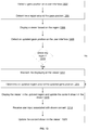
- FIG. 6 illustrates an example flow for protecting data based for a single user of a computing device, according to an embodiment.
- the example flow starts at operation 602, where a first presence of a first user relative to a computing device is determined.
- the first presence is determined based on images captured by an image sensor or based on gaze information tracked by an eye tracking system.
- the image sensor can be a component of the eye tracking system or can be a separate component.
- the eye tracking system can be a component of the computing device or can be a separate component.
- the first presence can be sensed by the eye tracking system and indication of the presence is provided from this system to the computing device. Additionally or alternatively, the computing device determines the presence from the captured images.
- an identifier of the first user is determined. Different types of identifiers are possible as described in connection with FIG. 4 .
- the first user logs into the computing device.
- the login information represents the identifier.
- facial recognition is applied to the images and the detected facial features (or a generated signature based on facial information) is used as the identifier.
- the identifier is used by the computing device to determine that the user is authorized to use the computing device.
- a second presence of a second user relative to the computing device is determined.
- the second presence is determined similarly to the operation 602.
- an update is caused to a user interface of the computing device based on the second presence such that the user interface changes from a first state to a second state.
- a number of other factors can be used to cause this update.
- a determination is made as to whether the second presence is authorized or not. This determination can depend on whether the first presence of the first user is still detected while the second presence is detected or not as described in connection with scenarios 410-440 of FIG. 4 . If the second presence is not authorized, the computing device changes the user interface to the second state that that properly perceiving the data presented on the user interface becomes harder or less user-friendly. Otherwise, the change may not be performed.
- the user interface is caused to change back to the first state.
- the computing device transitions the user interface from the second state to the first state based on the second presence no longer being sensed and the first presence of the first user still being sensed.
- FIG. 7 illustrates an example flow for protecting data based for multiple users of a computing device, according to an embodiment. Although two users are illustrated in connection with this flow (e.g., an authorized user and an authorized colleague), the flow similarly apply to a larger number of users.
- the example flow starts at operation 702, where a first presence of a first user relative to a computing device is determined.
- an identifier of the fist user is also determined.
- the operations 702 and 704 are similar to the operation 602 and 604 of FIG. 6 , respectively.
- a second presence of a second user relative to the computing device is determined.
- this determination involves images captured by the image sensor and/or eye tracking system, and/or gaze information generated by the eye tracking system.
- the start of the second presence can be in parallel to the start of the first presence or can occur later.
- the second user in this example flow represents an authorized colleague.
- ACL access control list
- an update to a user interface is caused based on the second presence being sensed while the first presence is no longer sensed, such that the user interface changes from a first state to a second state. For example, based on a user setting to automatically update the user interface when the first user is absent, the computing device transitions the user interface from the first state to the second state.
- this determination involves images captured by the image sensor and/or eye tracking system, gaze information generated by the eye tracking system, and/or the first user re-logging onto the computing device.
- the user interface is caused to change back to the first state.
- the computing device transitions the user interface from the second state to the first state based on the presence of the first user.
- a third presence of a second person relative to the computing device is determined.
- this determination involves images captured by the image sensor and/or eye tracking system, and/or gaze information generated by the eye tracking system.
- the third person is detected as being present while the first user and the second user are also present relative to the computing device.
- an update is caused to the user interface based on the third presence such that the user interface changes from the first state to a third state.
- This third state can be the same as the second state or can be a different state, where properly perceiving the presented data is made even harder, and/or where an image or video of the third person is presented in a window on the user interface.
- a number of other factors can be used to cause this update.
- a determination is made as to whether the third presence is authorized or not. This determination can depend on whether the first presence of the first user is still detected while the third presence is detected or not as described in connection with scenarios 450-480 of FIG. 4 . If the third presence is not authorized, the computing device changes the user interface to the third state. Otherwise, the change may not be performed.
- this determination involves images captured by the image sensor and/or eye tracking system, and/or gaze information generated by the eye tracking system.
- the user interface is caused to change back to the first state.
- the computing device transitions the user interface from the third state to the first state based on the third presence no longer being sensed and the first presence of the first user still being sensed.
- a computer system includes two (or more) computing devices that are communicatively coupled over a data network.
- Each of the computing device includes or is communicatively coupled with an eye tracking system and/or an image sensor.
- An image sensor can be a component of an eye tracking system or a separate component.
- a first presence of a first user relative to the first computing device is detected based on images captured by the image sensor and/or eye tracking system associated with this computing device, gaze information generated by the eye tracking system.
- the first presence of the user is validated (e.g., determined to be authorized or authenticated) based on a first identifier of the first user (e.g., login information or separate facial recognition).
- a first presence of a second user relative to the second computing device is determined and the second presence is validated (e.g., based on the relevant components of the second computing device and the relevant second identifier of the second user).
- an encryption key (or a set of keys) is used to encrypt data to be shared between the two computing devices over the data network.
- each computing device can share the symmetric key.
- Each computing device would use for encryption and decryption.
- each computing device is associated with a pair of a public key and a private key. The first computing device encrypts the data it sends to the second computing device with the public key of the second computing device. That second device decrypts the encrypted data with its private key. The same holds true for encryption by the second computing device and decryption by the first computing device.
- an encryption key (or, similarly, the set of keys).
- the encryption key is predefined or pre-negotiated between the two computing devices. Access thereto is controlled by detecting and validating the presences the presences of the two users. If one of the users is absent or if his or her presence is not validated, the access to the encryption key by the user's computing device is denied.
- the encryption key is generated based on the images sensed by the image sensors and/or eye tracking systems, or based on the gaze information.
- an key generation workflow is executed to generate the encryption key.
- a first image of the first user, a second image of the second user, first gaze information of the first user, and/or second gaze information of the second user are input to the workflow. For instance, this various information or hash therefrom are used to generate a random 128-bit key.
- FIG. 8 illustrates an example of a flow for encrypting data based on present detection, according to an embodiment.
- the example flow starts at operation 802, where the computer system determines the first presence of the first user relative to the first computing device.
- the first computing device detects the first presence based on images captured by the image sensor and/or eye tracking system of the first computing device, and/or gaze information generated by the eye tracking system.
- the computer system determines the first identifier of the first user. For example, the first computing device determines that the first user properly logged onto the first computing device based on login information and/or that the first user's presence is valid based on the images of this user (e.g., by applying facial recognition).
- the computer system determines the second presence of the second user relative to the second computing device.
- the second computing device detects the second presence based on images captured by the image sensor and/or eye tracking system of the second computing device, and/or gaze information generated by the eye tracking system.
- the computer system determines the second identifier of the second user. For example, the second computing device determines that the second user properly logged onto the second computing device based on login information and/or that the second user's presence is valid based on the images of this user (e.g., by applying facial recognition).
- the computer system causes data from the first computing device to be shared with the second computing device based on the first presence, the first identifier, the second presence, and the second identifier. For example, an encryption key is identified (e.g., accessed or generated) based on the presences and identifiers of the two users. The encryption is used in encrypting the data sent from the first computing device to the second computing device. if symmetric encryption is used, that same key can be used by the second computing device to decrypt the encrypted data and to encrypt other data to send to the first computing device. If asymmetric encryption is used, each of the computing devices uses the proper key to encrypt and decrypt data.
- an encryption key is identified (e.g., accessed or generated) based on the presences and identifiers of the two users. The encryption is used in encrypting the data sent from the first computing device to the second computing device. if symmetric encryption is used, that same key can be used by the second computing device to decrypt the encrypted data and to encrypt other
- the data includes a file on the first computing device. Based on the gaze of the first user on a user interface (or, similarly, display) of the first computing device, this file can be encrypted.
- FIGS. 9-13 relate to embodiments for using gaze information to bring forward data from an open window that is in a background of a user interface.
- the data is presented by a viewer that acts as a peephole through another window that is open in a foreground of the user interface and that occludes the background window.
- FIGS. 14-19 describe relate to embodiments for manipulating data based on gaze information. Data can be moved between locations on a computing device or between computing devices based on the gaze information. Presenting data in a viewer that would have been otherwise occluded and manipulating data are two examples of data access.
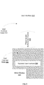
- FIG. 9 illustrates an example of a user interface 910 and a determination of a region 950 around a gaze position 940 of a user on the user interface 910, according to an embodiment.
- the user interface 910 when presented on a computing device (e.g., on a display of the computing device), the user interface 910 includes a first open window 920 in the foreground of the user interface 910 and a second open window 930 in the background of the user interface 910.
- An open window can be a window that presents data and can be rendered by the operating system (OS) of the computing device or an application (e.g., non-native application) running on the computing device.
- OS operating system
- application e.g., non-native application
- An open window in the foreground refers to a window that is open (e.g., could be minimized), active, and typically not occluded by other windows.
- An open window in the background refers to a window that is open, is not active, and can be but is not necessarily occluded by another open window.
- the first open window 920 in the foreground is referred to herein as a foreground window.
- the second open window 930 in the background is referred to herein as a background window.
- the foreground window 920 presents different elements including, for instance, text elements 922 and image elements 924 (e.g., an icon and a file name for a file in a file explorer window, or web content in a web browser). Portions of the background window 930 are occluded by the foreground window 920 as shown with the dashed lines in FIG. 9 .
- the background window also includes text elements 932 and 936 and image elements 934. The presentation of these elements 932-936 is hidden in the user interface 910 because of the occlusion by the foreground window 920.
- the gaze position 940 is detected by an eye tracking system of the computing device.
- the region 950 is defined around the gaze position 940.
- this region 950 is sub-region (or portion) of the user interface 910 that partially or fully surrounds the gaze position 940.
- the region 950 has predefined shape and size (e.g., a circle with a particular pixel radius) and is initially centered around the gaze position 940 (but maintaining this centering at all times is not necessary as further described next).
- the region 950 is used for multiple reasons. One reason is to define a viewer (e.g., a peephole as further described in connection with the next figures). Another reason relates to the gaze position 940. As the user's eyes tend to move and his or her gaze tend to change, the region 950 is used to define a margin around changes to the gaze position 940 before having to updated the viewer. For example, as long as the gaze falls within the region 950, the viewer can be maintained in place. As the gaze approaches the edge of the region 950, the update to the viewer can commence. Accordingly, the region 950 can be referred to herein as a gaze region.
- the size and/or shape of the region 950 can be specified in a user setting.
- the distance of the user to the user interface 910 (or the display) can be used to set the size and/or shape. This distance can be derived from the gaze information. In an illustration, the closer the user is, the larger the region 950 can become.
- the size and/or shape of the region 950 depends on the proximity of the gaze position 940 to the edge of the user interface 910 (or the display). For instance, while the gaze position 940 is in the center of the user interface, the region 950 has a predefined shape and size.
- the region 950 can be resized (e.g., made smaller) to maintain its shape (e.g., a circle) or, alternatively, its size and shape can stay the same but its position would be shifted such that the region 950 is fully contained in the user interface 910 while a portion of its edge is adjacent to the edge of the user interface 910.
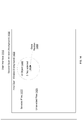
- FIG. 10 illustrates an example of a viewer 1010 presented on the user interface 910 of FIG 9 , according to an embodiment.
- the viewer 1010 is presented over the foreground window 920 and shows a snapshot of at least a portion of the background window 930.
- the viewer 1010 acts as a peephole through the foreground window 920 allowing the user to perceive the content of the background window 930 without having to activate and bring this window 930 to the foreground.
- the viewer 1010 has substantially the same shape as the region 950 or has a shape that can encompass the region 950. Further, the size of the viewer 1010 can be equal to or larger than the size of the region 950. Generally, the viewer 1010 is centered around the center of the region 950. Further and similarly to the sizing and shaping of the region 950, the size and/or shape of the viewer 1010 can depend on similar factors, including a user setting, the distance of the user to the user interface 910 (or the display), and the proximity of the gaze position 940 to the edge of the user interface 910 (or the display).
- the viewer 1010 can be activated by a keystroke or a combination of keystrokes or some other user input (e.g., a mouse click and hold).
- the activation trigger can be defined in a user setting. Once the activation trigger is detected, the computing device determines the gaze position 940, generates the region 950, takes a snapshot of the background window 930, determines a portion of the snapshot that corresponds to the location of the viewer 1010 on the user interface, and presents this portion of the snapshot in the viewer 1010.
- the viewer 1010 occludes portions of the text elements 922 and image elements 924 of the foreground window 920 because it is overlaid on top of the foreground window 920 (without necessarily deactivating the foreground window 920 or setting this window 920 to the background).
- the viewer 1010 also presents the text element 932 and the image elements 934 of the background window 930 because these elements 922 and 924 fall in the region 950 (as illustrated in FIG. 9 ).
- the other text element 936 of the background window 930 is not illustrated in FIG. 10 to emphasize that this element 936 is not in the viewer 1010 and would not be visible to the user because it is outside of the region 950.
- user input can select or switch between these windows (e.g., based on a mouse click or a keystroke).
- the viewer 1010 is updated to present the relevant portion of the selected background window.
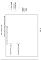
- FIG. 11 illustrates an example of updating the viewer 1010 to track the gaze position as the gaze of the user moves across the user interface 910, according to an embodiment.
- the updated viewer 1010 is shown as viewer 1110 in FIG. 11 .
- the viewer 1010 (and the region 950) are not updated on the user interface.
- an updated region is defined around the updated gaze positon. This updated region can be initially centered around the updated gaze position.
- the viewer 1110 is then generated and defined around the updated region.
- the viewer can be updated depending on the most current gaze position. In this way, the viewer is, in a way, a movable peephole that lets the user to move around the user interface and view different portions of the background window 930.
- the user's gaze shifts upward to the right.
- the updated viewer 1110 is accordingly presented upward to the right (relative to the viewer 1010 of FIG. 10 ).
- the updated viewer 1110 now shows only portions of the text elements 932 and image elements 934 from the background window 930.
- a portion of the other text elements 936 is falls within the updated viewer 1110.
- the updated viewer 1110 now shows this portion of the other text elements 936.
- the resolution of the shown portion of the background window 930 is updated.
- this user input indicates or the distance controls a warping operation or a zoom level to be applied to the snapshot of the background window 930.
- the closer the user is to the user interface 910 the more zooming out is applied to the snapshot in order to provide a wider view field of the background window 930. In this way, the viewer can act as a true peephole on a door, where the closer the user leans onto it on the inside, the wider the view of the outside becomes.
- FIG. 12 illustrates an example of relative positioning of the gaze position 940, the region 950, and the viewer 1010, and how the viewer 1010 is updated when the gaze position 940 approaches an edge of the region 950, according to an embodiment.
- the region 950 is initially centered around the gaze position 940.
- the viewer 1010 is also initially centered around the region 950.
- the gaze position 940 can approach the edge of the region 950 (illustrated in FIG. 12 as updated gaze position 1210).
- an inner perimeter of the region 950 is defined to determine whether this approaching occurred or not.
- the inner perimeter can be defined as a function of the outer boundary of the region 950 (e.g., 90% of the pixel radius of the region 950).
- the updated viewer 1220 can be presented simultaneously with the presentation of the viewer 1010 on the user interface 910 for a time period during which the updated gaze position 1210 is between the inner perimeter and the outer boundary of the region 950. If the updated gaze position 1220 moves back to the inside of the gaze region 950 by crossing the inner perimeter, the presentation of the updated viewer 1210 is removed from the user interface 910. If the updated gaze positon 1210 crosses the outer boundary of the region 950, an updated region is defined and the updated viewer 1220 can but need not be modified to be re-centered around the updated region.
- the transition between the viewers can be made more smooth and would appear more natural to the user.
- both viewers overlap (e.g., they have overlapping portions) and the updated viewer 1220 can be have a different transparency than that of the viewer 1010 (e.g., can be relatively more transparent).
- portions of the background window 930 can but need not be only shown in the viewer 1010 and not the updated viewer 1210.
- the properties (e.g., transparency) of the updated viewer 1220 to be similar to those of the viewer 1010 when presented.
- the relevant portions of the background window 930 are then presented in only the updated viewer 1220.
- FIG. 13 illustrates an example of a flow for presenting a viewer, according to an embodiment.
- the example flow is described in connection with a computer system.
- the computer system includes a computing device presenting a user interface and an eye tracking system communicatively coupled with the computing device. If the eye tracking system is integrated in the computing device, the computer system represents the computing device.
- the example flow starts at operation 1302, where the computer system detects a gaze position on the user interface.
- the computer system determines a region, such as a gaze region, around the gaze position.
- the computer system displays a viewer based on the region. For example, the viewer is centered around the region and has a size equal to or larger than the region.
- the viewer shows a snapshot of a portion of an open window that is in the background of the user interface.
- the computer system overlays the viewer on top of an open window that is in the foreground of the user interface without switching this window to the background.
- the computer system generates a snapshot of the background window and determines the portion of the snapshot that corresponds to the location of the viewer (e.g., based on coordinates of the viewer and coordinates of the snapshot, where a coordinate system can be defined relative to the user interface).
- the computer system presents this portion of the snapshot in the viewer.
- the computer system determines an updated gaze positon on the user interface.
- the computer system determines whether the updated gaze position falls within the region or not. If so, operation 1312 is performed. Otherwise, operation 1314 is performed.
- the updated gaze position is still within the region. Accordingly, the computer system maintains the displaying of the viewer. For example, the computer system does not update the presentation of the viewer. Further, the computer system may determine whether the updated gaze positon has approached an edge of the region and, if so, simultaneously presents an updated viewer as described in connection with FIG. 12 .
- the updated gaze position is outside of the region. Accordingly, the computer system determines an updated region around the updated gaze position.
- the computer system displays the viewer in the updated region and updates the content shown in the view. For example, the computer system displays an updated viewer that is centered around the updated region and determines a different portion of the snapshot that falls in the updated viewer. That position is presented in the updated viewer.
- the computer system receives user input associated with the shown content in the viewer.
- the user input indicates a warping operation or a zooming level to be applied to the snapshot.
- the user instead of receiving an explicit user input, the user leans towards (or away from the user interface).
- the user-to-user interface distance is estimated (e.g., based on the user's gaze) and that distance is used to control the warping operation or the zoom level.
- the computer system receives user input switching between the background windows.
- the computer system updates the content shown in the viewer based on the user input(s) and/or user-to-user interface distance of operation 1318. For instance, if the user input or the distance indicates a zooming out, the viewer is updated to show a zoomed out portion of the background window. If the user input indicates a selection of a different background window, the viewer is updated to show the relevant portion of a snapshot of this other background window.
- FIG. 14 illustrates an example of using a user interface (UI) object based on gaze information to manipulate data, according to an embodiment.
- UI user interface
- the embodiment is described in connection with examples of copying and pasting files from a source folder to a destination folder.
- a file is a type of the data that can be manipulated based on the UI object.
- the embodiment similarly apply to other type of data and/or of data manipulation.
- the data includes a document (e.g., a structured document like a Microsoft Word document) that is opened in an application (e.g. Microsoft Word application) on a first computing device.
- an application e.g. Microsoft Word application
- the UI object is usable to open the document in a different application (e.g., Google Docs application) on the first computing device or on a second computing device, and/or open the document in a different instance of the same application on the second computing device.
- the document opened in the application on the first computing device e.g., the first instance of the application
- has a state e.g., the Microsoft Word document is ten pages long, and page five is rendered in the Microsoft Word application on the first computing device.
- the other application e.g., Google Docs application
- the document is opened in the same state (e.g., page five is rendered).
- the user interface 1410 when presented on a computing device (e.g., on a display of the computing device), the user interface 1410 includes a first open window 1420 in the foreground of the user interface 1410 and a second open window 1430 in the background of the user interface 410.
- a different number of open windows is possible, whether in the foreground or the background.
- the foreground window 1420 can be a first open folder in the foreground (referred to herein as a foreground folder) listing the various available files data
- the background window 1430 can be a second open folder in the background (referred to herein as a background folder) to which some or all of the available files can be copied.
- the foreground folder is a source folder and the background folder is a destination folder.
- the two folders are on the same computing device. Nonetheless, and as illustrated in connection with FIG. 18 the two folders can be on separate computing devices.
- a UI object 1440 is used to place data available from the foreground window 1420 into the background window 1430. For example, selected files 1422 are copied from the foreground window 1420 (or the source folder) and pasted in the background window 1430 (or the destination folder). Other files 1424 available from the foreground window 1420 may not be selected and, thus, are not copied to the background window 1430.
- the placing of the data e.g., the pasting of the selected files 1422
- Various triggers are possible to invoke the UI object 1440.
- user input such as a particular combination of keystrokes, a particular keystroke after the selection and copying of the selected files 1422, can be used to activate the UI object 1440. This user input can be received prior to, in parallel with, or after selecting and/or copying the selected files 1422.
- the UI object 1440 is positioned on the user interface 1410 at the gaze position 1450 at the time the UI object 1440 was invoked.
- the UI object 1440 is centered around the gaze position 1450 and is presented in the foreground of the user interface 1410 as an overlay on top of the foreground window 1420. If the gaze position 1450 changes thereafter based on the movement of the user's gaze, the position of the UI object 1440 is changed to track the updated gaze position.
- the UI object 1440 can have a predefined shape and size such as a bubble or a circle. Of course, other geometric shapes are possible and can be specified in a user setting. The shape, size, and/or other visual properties of the UI object 1440 may change depending on the amount of manipulated data. For example, the larger the number of selected files 1422 is, the larger the bubble can be made or the more alerting its color becomes (e.g., gradually changes from green to yellow and from yellow to red with an increase in the number of selected files 1422).
- the UI object 1440 can present various types of information about the manipulated data.
- FIG. 14 illustrates one example of such information.
- the UI object 1440 shows the amount 1442 of the manipulated data (e.g., the total number of selected and copied files 1422).
- FIG. 15 illustrates another example of information presented in the UI object, according to an embodiment.
- user input such as a particular keystroke or a consistent gaze at a same gaze position of a time period exceeding a time threshold
- the UI object 1440 is updated and the updated UI object (shown as element 1510) is expanded to show the details 1420.
- the updated UI object 1510 has a different shape (e.g., a rectangle instead of a circular bubble) and its size is increased to provide relevant details (e.g., in the case of files, the file names and source locations of the selected files 1422).
- the same user input or a different one also pauses the movement of the updated UI object 1510.
- the updated UI object 1510 is shown at a constant location on the user interface 1410 (e.g., at a location corresponding to the last gaze position prior to receiving the user input).
- the user can pause the data manipulation. Additional user input can be received to resume or to cancel the data manipulation. If resumed, the updated UI object 1510 can be changed back to the original UI object 1440 and the UI object 1440 would follow the gaze position from that point on. If canceled, the updated UI object 1510 is removed from the user interface 1410.
- FIG. 16 illustrates an example of completing the data manipulation by using the UI object 1440, according to an embodiment.
- the UI object 1440 follows the user's gaze.
- the computing device upon detecting that the gaze position 1610 is over the background window 1430, the computing device presents the UI object 1440 at that position over the background window 1430 without bringing the background window 1430 to the foreground of the user interface 1410.
- the computing device Upon receiving user input to complete the data manipulation (e.g., a particular keystroke or keystroke combination, a mouse click, etc.) while the UI object 1440 is over the background window 1430 (or, equivalently, the gaze position 1610 is at that location), the computing device completes the data manipulation .
- the computing device places the selected and copied data in the background window 1430 without activating it (e.g., pastes the selected and copied files 1422 in the destination folder without bringing this folder to the foreground of the user interface 1410).
- the computing device can update the content of the UI object 1440 to show the progress of the data manipulation completion.
- the UI object 1440 indicates visually the percentage of the copied data (e.g., the number of the pasted files). This visual indication can be a number (e.g., a percentage), a status bar, and/or a check sign (e.g. upon the completion).
- FIG. 17 illustrates an example of the result of competing the data manipulation based on the UI object 1440, according to an embodiment.
- the UI object 1440 is dismissed and no longer presented on the user interface.
- the data is placed in the background window 1430 without activating it.
- element 1710 outlined with dashed lines to emphasize the placed data 1710 is now in the background window 1730 but the presentation of this placed data 1710 is occluded by the foreground window 1420.
- the copied files are pasted in the destination folder without bringing this folder to the foreground of the user interface 1410.
- FIG. 18 illustrates an example of data manipulation across two computing devices based on a UI object, according to an embodiment. Although two computing devices are illustrated, the embodiment similarly apply to a larger number of computing devices.
- the two computing devices are communicatively coupled over a data network and each of these devices uses a separate eye tracking system.
- the two eye tracking systems are also communicatively coupled over the data network.
- the two computing devices are in proximity of each other such that a user can gaze at one and then move his or her gaze to the next one.
- a single coordinate system is defined for the two eye tracking systems (e.g., its origin is at the bottom left corner of the user interface of the computing device that is on the left hand side of the other one). In this way, gaze position and information about the UI object (e.g., its coordinate location) can be referenced against the coordinate system and exchanged between the two computing devices.
- the first computing device presents a first user interface 1810 (e.g., on a display of the first computing device).
- the first user interface 1810 includes a first source folder 1820 that contains a number of files (or, more generally, a foreground window that presents data). Some of these files (or data) are selected based on user input (shown as selected files 1822) while remaining ones are not selected (shown as unselected files 1824).
- a UI object 1830 is invoked and follow the gaze position.
- the user's gaze moves 1840 from the user interface 1810 of the first computing device to a user interface 1850 of the second computing device (e.g., presented on a display of the second computing device).
- the information about the UI object 1830 is sent from the first computing device to the second computing device over the data network.
- the information includes identifiers of the copied files (or the copied files themselves) and/or other content of the UI object 1830 (e.g. the number of copied files or the total amount of copied data, details about the files or data, etc.), visual properties of the UI object 1830 (e.g., shape, size, color, etc.)
- the second computing device Based on the gaze position on the second user interface 1850 and the received information about the UI object 1830, the second computing device displays the UI object 1830 on the user interface (e.g., in the foreground). Conversely, the first computing device dismisses the presentation of the UI object 1830.
- the second computing device preserves the visual properties of the UI object 1830 such that the move from the firs user interface 1810 to the second user interface 1850 appears seamless to the user.
- the second computing device changes one or more of the visual properties of the UI object 1830 (e.g., changes its color) to alert the user of the transition of the UI object 1830 from the firs user interface 1810 to the second user interface 1850.
- the content of the UI object 1830 are generally not altered such that the UI object 1830 can show the same information on the second user interface 1850 that it would have been capable to show on the first user interface 1810.
- the second user interface 1850 When presented, the second user interface 1850 includes a second destination folder 1860 to which the files are to be copied (or, more generally, a background window in which the data should be placed).
- the second computing device Upon receiving user input and while the UI object 1830 is positioned over the destination folder 1860 (or, equivalently, the gaze position is over that folder 1860), the second computing device pasts the files to the destination folder 1860 (shown as copied files 1862), without activating the destination folder 1860 (e.g., without bringing it to the foreground).
- the selected files 1822 are automatically received from the first computing device via a push therefrom when the gaze position moves to the second computing device.
- the second computing device identifies the selected files 1822 based on the information passed with the UI object 1830 and pulls (e.g., request and receive) these files 1822 from the first computing device, in both examples, the second computing device pastes the received files to the second destination folder 1860.
- FIG. 18 describes sending selected files to a folder in a background of a user interface, the embodiment similarly applies to sending such files to a folder in a foreground of the user interface.
- FIG. 19 illustrates an example flow for manipulation data based on a UI object, according to an embodiment.
- the flow is described in connection with a computer system.
- the computer system can be a single computing device, where the data is copied from one foreground window and placed in a background window of a user interface of the computing device.
- the computer system can include a plurality of computing devices, where the data is copied from a foreground window of a first computing device and placed in an open window (whether foreground or background) of a second computing device.
- the example flow starts at operation 1902, where the computer system receives first user input that selects data from a source. For example, the user input selects a number of files from a source folder.
- the computer system detects a first gaze position on a user interface.
- the computer system presents a UI object on the user interface at the first gaze position.
- the UI object can be invoked based on the selection of the data and/or based on additional user input specific to invoking the UI object.
- the computer system moves the UI object as the gaze position changes.
- the UI object shows the total amount of selected data (e.g., the total number of selected files).
- the computer system tracks the gaze position as it moves around the user interface and updates the presentation of the UI object to follow the gaze position. Further, the computer system identifies the selected data and generates a summary thereof (e.g., the total amount of selected data) and presents this summary as content of the UI object.
- the computer system updates the UI object to show details about the selected data based on second user input. For example, the computer system receives the second user input requesting the UI object to be paused and its content to be expanded. The computer system accordingly responds.
- the computer system detects a second gaze position on a destination. For example, based on tracking the gaze position, the computer system determines that now the user is gazing over a location on the destination.
- the destination can be a background window on the user interface or another open window on a different interface (e.g., when two interfaces are available on two computing devices).
- the computer system presents the UI object over the destination. For example, the computer system updates the presentation of the UI object such that it is shown at the location of the second gaze position.
- the computer system receives third user input to place the data in the destination. Based on the UI object being positioned over the destination (or, equivalently, based on the second gaze position) and in response to the third use input, the computer system initiates the placing of the selected data in the destination. For example, in the context of copying files, the computer system starts pasting the copied files.
- the computer system shows the progress in the UI object of placing the data in the destination. For example, the computer system continuously monitors the amount of the copied data that has been placed in the destination (e.g., the number of the pasted files) and updates the presentation of the UI object to indicate this amount.
- the amount of the copied data that has been placed in the destination e.g., the number of the pasted files
- the computer system places the selected data in the destination. This operation can occur in parallel to operation 1918.
- the computer system updates the UI object to indicate the completion and can thereafter, automatically or based on user input, dismiss the UI object.
- any detail discussed with regard to one embodiment may or may not be present in all contemplated versions of that embodiment.
- any detail discussed with regard to one embodiment may or may not be present in all contemplated versions of other embodiments discussed herein.
- the absence of discussion of any detail with regard to embodiment herein shall be an implicit recognition that such detail may or may not be present in any version of any embodiment discussed herein.
- circuits, systems, networks, processes, and other elements in the disclosure may be shown as components in block diagram form in order not to obscure the embodiments in unnecessary detail.
- well-known circuits, processes, algorithms, structures, and techniques may be shown without unnecessary detail in order to avoid obscuring the embodiments.
- individual embodiments may be described as a process which is depicted as a flowchart, a flow diagram, a data flow diagram, a structure diagram, or a block diagram. Although a flowchart may describe the operations as a sequential process, many of the operations can be performed in parallel or concurrently. In addition, the order of the operations may be re-arranged. A process may be terminated when its operations are completed, but could have additional steps not discussed or included in a figure. Furthermore, not all operations in any particularly described process may occur in all embodiments. A process may correspond to a method, a function, a procedure, a subroutine, a subprogram, etc.
- a process corresponds to a function
- its termination corresponds to a return of the function to the calling function or the main function.
- a computer program comprises instructions which, when the program is executed by a computer system (or by one or more processors of a computer system), cause the computer system to perform the method according to any of the embodiments disclosed herein (for example those disclosed among the enumerated embodiments or the claims).
- machine-readable medium includes, but is not limited to transitory and non-transitory, portable or fixed storage devices, optical storage devices, wireless channels and various other mediums capable of storing, containing or carrying instruction(s) and/or data.
- a code segment or machine-executable instructions may represent a procedure, a function, a subprogram, a program, a routine, a subroutine, a module, a software package, a class, or any combination of instructions, data structures, or program statements.
- a code segment may be coupled to another code segment or a hardware circuit by passing and/or receiving information, data, arguments, parameters, or memory contents. Information, arguments, parameters, data, etc. may be passed, forwarded, or transmitted via any suitable means including memory sharing, message passing, token passing, network transmission, etc.
- embodiments of the disclosure may be implemented, at least in part, either manually or automatically.
- Manual or automatic implementations may be executed, or at least assisted, through the use of machines, hardware, software, firmware, middleware, microcode, hardware description languages, or any combination thereof.
- the program code or code segments to perform the necessary tasks may be stored in a machine readable medium.
- a processor or processors may perform the necessary tasks.
- a first thing based on a second thing may mean that the first thing is based solely on the second thing, or that the first thing is based on the second thing as well as one or more additional things.
Landscapes
- Engineering & Computer Science (AREA)
- Theoretical Computer Science (AREA)
- General Engineering & Computer Science (AREA)
- Physics & Mathematics (AREA)
- General Physics & Mathematics (AREA)
- Human Computer Interaction (AREA)
- Computer Security & Cryptography (AREA)
- Software Systems (AREA)
- Computer Hardware Design (AREA)
- General Health & Medical Sciences (AREA)
- Health & Medical Sciences (AREA)
- Bioethics (AREA)
- Nonlinear Science (AREA)
- Computer Networks & Wireless Communication (AREA)
- Signal Processing (AREA)
- Optics & Photonics (AREA)
- Databases & Information Systems (AREA)
- Data Mining & Analysis (AREA)
- Automation & Control Theory (AREA)
- Chemical & Material Sciences (AREA)
- Computing Systems (AREA)
- Crystallography & Structural Chemistry (AREA)
- Oral & Maxillofacial Surgery (AREA)
- Multimedia (AREA)
- Bioinformatics & Computational Biology (AREA)
- Bioinformatics & Cheminformatics (AREA)
- Evolutionary Computation (AREA)
- Computer Vision & Pattern Recognition (AREA)
- Evolutionary Biology (AREA)
- Artificial Intelligence (AREA)
- Life Sciences & Earth Sciences (AREA)
- User Interface Of Digital Computer (AREA)
Applications Claiming Priority (1)
| Application Number | Priority Date | Filing Date | Title |
|---|---|---|---|
| US201762583666P | 2017-11-09 | 2017-11-09 |
Publications (2)
| Publication Number | Publication Date |
|---|---|
| EP3486752A1 true EP3486752A1 (de) | 2019-05-22 |
| EP3486752B1 EP3486752B1 (de) | 2021-09-01 |
Family
ID=64270731
Family Applications (4)
| Application Number | Title | Priority Date | Filing Date |
|---|---|---|---|
| EP18205471.8A Ceased EP3483763A1 (de) | 2017-11-09 | 2018-11-09 | Verfahren zum senden von daten |
| EP18205468.4A Active EP3486752B1 (de) | 2017-11-09 | 2018-11-09 | Verfahren zur aktualisierung einer benutzerschnittstelle in einem computersystem |
| EP18205473.4A Withdrawn EP3483764A1 (de) | 2017-11-09 | 2018-11-09 | Verfahren zur aktualisierung eines benutzerschnittstelle |
| EP18205466.8A Ceased EP3486820A1 (de) | 2017-11-09 | 2018-11-09 | Verfahren zum austauschen von daten zwischen zwei datenverarbeitungsvorrichtungen |
Family Applications Before (1)
| Application Number | Title | Priority Date | Filing Date |
|---|---|---|---|
| EP18205471.8A Ceased EP3483763A1 (de) | 2017-11-09 | 2018-11-09 | Verfahren zum senden von daten |
Family Applications After (2)
| Application Number | Title | Priority Date | Filing Date |
|---|---|---|---|
| EP18205473.4A Withdrawn EP3483764A1 (de) | 2017-11-09 | 2018-11-09 | Verfahren zur aktualisierung eines benutzerschnittstelle |
| EP18205466.8A Ceased EP3486820A1 (de) | 2017-11-09 | 2018-11-09 | Verfahren zum austauschen von daten zwischen zwei datenverarbeitungsvorrichtungen |
Country Status (4)
| Country | Link |
|---|---|
| US (4) | US10678116B1 (de) |
| EP (4) | EP3483763A1 (de) |
| CN (3) | CN109766709A (de) |
| ES (1) | ES2894941T3 (de) |
Families Citing this family (44)
| Publication number | Priority date | Publication date | Assignee | Title |
|---|---|---|---|---|
| US11592723B2 (en) | 2009-12-22 | 2023-02-28 | View, Inc. | Automated commissioning of controllers in a window network |
| US11054792B2 (en) | 2012-04-13 | 2021-07-06 | View, Inc. | Monitoring sites containing switchable optical devices and controllers |
| US10964320B2 (en) | 2012-04-13 | 2021-03-30 | View, Inc. | Controlling optically-switchable devices |
| US12400651B2 (en) | 2012-04-13 | 2025-08-26 | View Operating Corporation | Controlling optically-switchable devices |
| KR102336168B1 (ko) | 2014-03-05 | 2021-12-07 | 뷰, 인크. | 스위칭가능한 광 디바이스들 및 제어기들을 포함하는 사이트들 모니터링 |
| EP4227728A1 (de) | 2017-03-08 | 2023-08-16 | Meta Platforms Technologies, LLC | Weitwinkelfilter mit variabler neutraler dichte |
| US11294113B2 (en) | 2017-07-17 | 2022-04-05 | Gary Sharp Innovations, Llc | Wide-angle compensation of uniaxial retarder stacks |
| US11294530B2 (en) * | 2017-08-07 | 2022-04-05 | Microsoft Technology Licensing, Llc | Displaying a translucent version of a user interface element |
| US10678116B1 (en) | 2017-11-09 | 2020-06-09 | Facebook Technologies, Llc | Active multi-color PBP elements |
| EP3484164B1 (de) * | 2017-11-13 | 2023-08-16 | Nagravision Sàrl | Verfahren zur steuerung der anzeige von mindestens einem inhalt auf einem bildschirm |
| US11249355B2 (en) | 2018-01-29 | 2022-02-15 | Gary Sharp Innovations, Llc | Color switch for reduced color cross-talk |
| EP3746822A4 (de) | 2018-01-29 | 2022-01-12 | Gary Sharp Innovations, LLC | Hohle optische dreiwege-elemente |
| JP7284182B2 (ja) | 2018-03-02 | 2023-05-30 | メタ プラットフォームズ テクノロジーズ, リミテッド ライアビリティ カンパニー | 偏光基底ベクトルの変換のためのリターダスタックペア |
| US11157077B2 (en) * | 2018-04-16 | 2021-10-26 | Google Llc | Method and system for dual mode eye tracking on wearable heads-up display |
| US10803288B2 (en) * | 2018-04-24 | 2020-10-13 | International Business Machines Corporation | Methods and systems for accessing computing systems with biometric identification |
| KR102621809B1 (ko) * | 2018-11-02 | 2024-01-09 | 삼성전자주식회사 | 저전력 상태에서 디스플레이를 통해 화면을 표시하기 위한 전자 장치 및 그의 동작 방법 |
| CN110389801B (zh) * | 2019-06-05 | 2022-08-30 | 北京梧桐车联科技有限责任公司 | 一种信息处理方法、装置、车载设备及存储介质 |
| CN110266881B (zh) * | 2019-06-18 | 2021-03-12 | Oppo广东移动通信有限公司 | 应用控制方法及相关产品 |
| US11686942B2 (en) * | 2019-09-12 | 2023-06-27 | Meta Platforms Technologies, Llc | Polarization-based processing of unpolarized image light |
| US11271747B2 (en) * | 2019-09-16 | 2022-03-08 | Lawrence Livermore National Security, Llc | Optical authentication of images |
| CN111176504B (zh) * | 2019-12-18 | 2021-12-24 | 华为技术有限公司 | 一种界面元素的显示方法及电子设备 |
| CN113448088A (zh) * | 2020-03-28 | 2021-09-28 | 华为技术有限公司 | 增强现实设备 |
| CN118192800B (zh) | 2020-03-31 | 2025-04-25 | 托比股份公司 | 用于对可视化数据进行预处理的方法、计算机程序产品和处理电路系统 |
| US20220091560A1 (en) * | 2020-09-24 | 2022-03-24 | Facebook Technologies, Llc | Lightguide based holographic display |
| US20220107517A1 (en) * | 2020-10-05 | 2022-04-07 | Facebook Technologies, Llc | Off-axis focusing geometric phase lens and system including the same |
| CN112506345B (zh) * | 2020-12-10 | 2024-04-16 | 北京达佳互联信息技术有限公司 | 一种页面显示方法、装置、电子设备及存储介质 |
| US11847248B2 (en) * | 2020-12-16 | 2023-12-19 | Cigna Intellectual Property, Inc. | Automated viewpoint detection and screen obfuscation of secure content |
| US20220221932A1 (en) * | 2021-01-12 | 2022-07-14 | Microsoft Technology Licensing, Llc | Controlling a function via gaze detection |
| US11094042B1 (en) | 2021-03-12 | 2021-08-17 | Flyreel, Inc. | Face detection and blurring methods and systems |
| KR20240000484A (ko) * | 2021-04-29 | 2024-01-02 | 루머스 리미티드 | 근안 디스플레이의 시야 확대 |
| US11871147B2 (en) | 2021-06-09 | 2024-01-09 | Microsoft Technology Licensing, Llc | Adjusting participant gaze in video conferences |
| US11709411B2 (en) * | 2021-07-16 | 2023-07-25 | Meta Platforms Technologies, Llc | Display with image light steering |
| US11953796B2 (en) * | 2021-07-21 | 2024-04-09 | Meta Platforms Technologies, Llc | Tunable polarization holographic lenses |
| US20230045957A1 (en) | 2021-08-12 | 2023-02-16 | Facebook Technologies, Llc | Multi-source light-guiding illuminator |
| US11876795B2 (en) * | 2021-08-27 | 2024-01-16 | Bank Of America Corporation | Resource processing terminal device with enhanced secure resource transmissions based on image capture |
| US12547694B2 (en) * | 2021-09-21 | 2026-02-10 | Lenovo (United States) Inc. | Systems and methods for managing access to data based on a geographic location requirement |
| JP7799430B2 (ja) * | 2021-10-25 | 2026-01-15 | キヤノン株式会社 | 画像処理装置、制御方法及びプログラム |
| US12560806B2 (en) | 2021-12-06 | 2026-02-24 | Meta Platforms Technologies, Llc | Directional illuminator and display apparatus with switchable diffuser |
| US20230176376A1 (en) * | 2021-12-06 | 2023-06-08 | Meta Platforms Technologies, Llc | Lightguides with color- and time-sequential gratings |
| WO2023156475A1 (en) * | 2022-02-15 | 2023-08-24 | Trinamix Gmbh | Method for protecting information displayed on a display device and display device |
| US12429651B2 (en) | 2022-05-12 | 2025-09-30 | Meta Platforms Technologies, Llc | Waveguide with tunable bulk reflectors |
| CN115310151B (zh) * | 2022-08-15 | 2025-12-02 | 北京胜龙全息科技发展有限公司 | 一种显示信息保护方法及装置 |
| US11823850B1 (en) * | 2022-10-28 | 2023-11-21 | Dell Products L.P. | Information handling system keyboard backlight having mini-LED integrated light guide arrangement |
| SE547371C2 (en) * | 2023-05-02 | 2025-07-15 | Tobii Ab | An eye tracking system and methods of using an eye tracking system |
Citations (8)
| Publication number | Priority date | Publication date | Assignee | Title |
|---|---|---|---|---|
| US6152563A (en) * | 1998-02-20 | 2000-11-28 | Hutchinson; Thomas E. | Eye gaze direction tracker |
| US6204828B1 (en) | 1998-03-31 | 2001-03-20 | International Business Machines Corporation | Integrated gaze/manual cursor positioning system |
| US7113170B2 (en) | 2000-05-16 | 2006-09-26 | Swisscom Mobile Ag | Method and terminal for entering instructions |
| US20110175932A1 (en) * | 2010-01-21 | 2011-07-21 | Tobii Technology Ab | Eye tracker based contextual action |
| US20120272179A1 (en) * | 2011-04-21 | 2012-10-25 | Sony Computer Entertainment Inc. | Gaze-Assisted Computer Interface |
| US20130169560A1 (en) | 2012-01-04 | 2013-07-04 | Tobii Technology Ab | System for gaze interaction |
| US20140247232A1 (en) | 2013-03-01 | 2014-09-04 | Tobii Technology Ab | Two step gaze interaction |
| US20150128075A1 (en) * | 2012-05-11 | 2015-05-07 | Umoove Services Ltd. | Gaze-based automatic scrolling |
Family Cites Families (32)
| Publication number | Priority date | Publication date | Assignee | Title |
|---|---|---|---|---|
| US20080177994A1 (en) * | 2003-01-12 | 2008-07-24 | Yaron Mayer | System and method for improving the efficiency, comfort, and/or reliability in Operating Systems, such as for example Windows |
| WO2008038368A1 (en) * | 2006-09-28 | 2008-04-03 | Navitime Japan Co., Ltd. | Window display system |
| GB2445373B (en) * | 2007-01-03 | 2010-12-29 | Advanced Risc Mach Ltd | A data processing apparatus and method for managing access to a display buffer |
| US7933408B2 (en) * | 2007-06-15 | 2011-04-26 | Microsoft Corporation | Asynchronous download |
| CN101334725B (zh) * | 2007-06-29 | 2011-05-25 | 联想(北京)有限公司 | 提高窗口显示性能的方法与装置 |
| US8922480B1 (en) * | 2010-03-05 | 2014-12-30 | Amazon Technologies, Inc. | Viewer-based device control |
| KR101660742B1 (ko) * | 2010-05-31 | 2016-09-28 | 엘지전자 주식회사 | 이동 단말기 및 그 제어방법 |
| US8625847B2 (en) * | 2011-03-21 | 2014-01-07 | Blackberry Limited | Login method based on direction of gaze |
| JP5907163B2 (ja) * | 2011-03-30 | 2016-04-20 | 日本電気株式会社 | データ関連度判定装置、データ関連度判定方法、および、プログラム |
| EP2551110B1 (de) * | 2011-07-29 | 2014-04-23 | Creator Technology B.V. | Stoßfeste Vorrichtung mit optischer Schicht |
| US8973149B2 (en) * | 2013-01-14 | 2015-03-03 | Lookout, Inc. | Detection of and privacy preserving response to observation of display screen |
| US20140201527A1 (en) * | 2013-01-17 | 2014-07-17 | Zohar KRIVOROT | Systems and methods for secure and private delivery of content |
| JP2014157466A (ja) * | 2013-02-15 | 2014-08-28 | Sony Corp | 情報処理装置及び記憶媒体 |
| US9791921B2 (en) * | 2013-02-19 | 2017-10-17 | Microsoft Technology Licensing, Llc | Context-aware augmented reality object commands |
| CN104216644A (zh) * | 2013-05-29 | 2014-12-17 | 顾红波 | 一种映射被遮挡区的系统和方法 |
| US9626493B2 (en) * | 2013-06-08 | 2017-04-18 | Microsoft Technology Licensing, Llc | Continuous digital content protection |
| JP2015088086A (ja) * | 2013-11-01 | 2015-05-07 | ソニー株式会社 | 情報処理装置および情報処理方法 |
| US20150170446A1 (en) * | 2013-12-12 | 2015-06-18 | Microsoft Corporation | Access tracking and restriction |
| US9846522B2 (en) * | 2014-07-23 | 2017-12-19 | Microsoft Technology Licensing, Llc | Alignable user interface |
| US10402061B2 (en) | 2014-09-28 | 2019-09-03 | Microsoft Technology Licensing, Llc | Productivity tools for content authoring |
| US20160124505A1 (en) * | 2014-11-05 | 2016-05-05 | Kobo Incorporated | Operating an electronic personal display using eye movement tracking |
| WO2016085212A1 (ko) | 2014-11-24 | 2016-06-02 | 삼성전자 주식회사 | 디스플레이를 제어하는 전자 장치 및 방법 |
| EP3038298A1 (de) * | 2014-12-23 | 2016-06-29 | Telefonica Digital España, S.L.U. | Computerimplementiertes Verfahren zum Schutz von klassifiziertem Inhalt in einer Computervorrichtung und Computerprogramme dafür |
| US9886598B2 (en) * | 2014-12-29 | 2018-02-06 | Paypal, Inc. | Automatic adjustment of a display to obscure data |
| EP3046007B1 (de) * | 2015-01-15 | 2019-03-27 | Nokia Technologies OY | Verfahren, Vorrichtung und Computerprogrammprodukt zur Ermöglichung von Kommunikation zwischen Vorrichtungen auf Basis von Blickkontakt |
| JP6580515B2 (ja) * | 2016-04-28 | 2019-09-25 | 株式会社ソニー・インタラクティブエンタテインメント | 情報処理装置およびデータコピー方法 |
| US10586535B2 (en) * | 2016-06-10 | 2020-03-10 | Apple Inc. | Intelligent digital assistant in a multi-tasking environment |
| US10353583B2 (en) * | 2016-06-14 | 2019-07-16 | International Business Machines Corporation | Efficient temporary dynamic anchor points within and between application document(s) |
| US9898901B1 (en) * | 2016-11-30 | 2018-02-20 | Bank Of America Corporation | Physical security system for computer terminals |
| KR102601052B1 (ko) * | 2017-02-23 | 2023-11-09 | 매직 립, 인코포레이티드 | 가변 파워 반사기를 갖는 디스플레이 시스템 |
| US10607035B2 (en) * | 2017-08-31 | 2020-03-31 | Yeo Messaging Ltd. | Method of displaying content on a screen of an electronic processing device |
| US10678116B1 (en) | 2017-11-09 | 2020-06-09 | Facebook Technologies, Llc | Active multi-color PBP elements |
-
2018
- 2018-05-25 US US15/990,393 patent/US10678116B1/en active Active
- 2018-11-09 US US16/186,195 patent/US11592898B2/en active Active
- 2018-11-09 EP EP18205471.8A patent/EP3483763A1/de not_active Ceased
- 2018-11-09 CN CN201811333151.3A patent/CN109766709A/zh active Pending
- 2018-11-09 EP EP18205468.4A patent/EP3486752B1/de active Active
- 2018-11-09 US US16/186,205 patent/US20190138093A1/en not_active Abandoned
- 2018-11-09 CN CN201811333149.6A patent/CN109765994B/zh active Active
- 2018-11-09 EP EP18205473.4A patent/EP3483764A1/de not_active Withdrawn
- 2018-11-09 EP EP18205466.8A patent/EP3486820A1/de not_active Ceased
- 2018-11-09 CN CN201811333145.8A patent/CN109766106A/zh active Pending
- 2018-11-09 US US16/186,201 patent/US10955912B2/en active Active
- 2018-11-09 ES ES18205468T patent/ES2894941T3/es active Active
Patent Citations (9)
| Publication number | Priority date | Publication date | Assignee | Title |
|---|---|---|---|---|
| US6152563A (en) * | 1998-02-20 | 2000-11-28 | Hutchinson; Thomas E. | Eye gaze direction tracker |
| US6204828B1 (en) | 1998-03-31 | 2001-03-20 | International Business Machines Corporation | Integrated gaze/manual cursor positioning system |
| US7113170B2 (en) | 2000-05-16 | 2006-09-26 | Swisscom Mobile Ag | Method and terminal for entering instructions |
| US20110175932A1 (en) * | 2010-01-21 | 2011-07-21 | Tobii Technology Ab | Eye tracker based contextual action |
| US20120272179A1 (en) * | 2011-04-21 | 2012-10-25 | Sony Computer Entertainment Inc. | Gaze-Assisted Computer Interface |
| US20130169560A1 (en) | 2012-01-04 | 2013-07-04 | Tobii Technology Ab | System for gaze interaction |
| US20150128075A1 (en) * | 2012-05-11 | 2015-05-07 | Umoove Services Ltd. | Gaze-based automatic scrolling |
| US20140247232A1 (en) | 2013-03-01 | 2014-09-04 | Tobii Technology Ab | Two step gaze interaction |
| US9619020B2 (en) | 2013-03-01 | 2017-04-11 | Tobii Ab | Delay warp gaze interaction |
Also Published As
| Publication number | Publication date |
|---|---|
| US10678116B1 (en) | 2020-06-09 |
| EP3483763A1 (de) | 2019-05-15 |
| CN109765994A (zh) | 2019-05-17 |
| ES2894941T3 (es) | 2022-02-16 |
| EP3483764A1 (de) | 2019-05-15 |
| CN109765994B (zh) | 2022-09-09 |
| US20190138740A1 (en) | 2019-05-09 |
| US11592898B2 (en) | 2023-02-28 |
| US10955912B2 (en) | 2021-03-23 |
| CN109766106A (zh) | 2019-05-17 |
| US20190138738A1 (en) | 2019-05-09 |
| CN109766709A (zh) | 2019-05-17 |
| US20190138093A1 (en) | 2019-05-09 |
| EP3486752B1 (de) | 2021-09-01 |
| EP3486820A1 (de) | 2019-05-22 |
Similar Documents
| Publication | Publication Date | Title |
|---|---|---|
| EP3486752B1 (de) | Verfahren zur aktualisierung einer benutzerschnittstelle in einem computersystem | |
| JP7840429B2 (ja) | ユーザ認証及びデバイス管理のためのデバイス、方法、及びグラフィカルユーザインタフェース | |
| US10591729B2 (en) | Wearable device | |
| US20170123491A1 (en) | Computer-implemented gaze interaction method and apparatus | |
| US20150124069A1 (en) | Information processing device and information processing method | |
| KR102862951B1 (ko) | 사용자 식별에 기초한 사용자 인터페이스들 및 디바이스 설정들 | |
| WO2016109092A1 (en) | Automatic adjustment of a display to obscure data | |
| US10185843B2 (en) | Public viewing security | |
| US20260086636A1 (en) | Controlling a function via gaze detection | |
| CN104331168A (zh) | 显示调整方法和电子设备 | |
| KR20150032019A (ko) | 시선 추적 기반의 사용자 인터페이스 방법 및 그 장치 | |
| KR20160074388A (ko) | 전자 장치의 제어 방법 및 장치 | |
| US20200221021A1 (en) | Electronic device, control device, and control method | |
| US20250373579A1 (en) | Message processing method, electronic device, and readable storage medium | |
| JP2016126687A (ja) | ヘッドマウントディスプレイ、操作受付方法および操作受付プログラム | |
| US11842119B2 (en) | Display system that displays virtual object, display device and method of controlling same, and storage medium | |
| US20250306744A1 (en) | Information handling system display privacy glasses with touch detection frame | |
| US20250307476A1 (en) | Information handling system display privacy glasses | |
| US12511443B2 (en) | System and method for data protection based on proximity and viewing angle | |
| CN121980629A (zh) | 一种屏幕隐私控制方法、系统、可读存储介质及电子设备 |
Legal Events
| Date | Code | Title | Description |
|---|---|---|---|
| PUAI | Public reference made under article 153(3) epc to a published international application that has entered the european phase |
Free format text: ORIGINAL CODE: 0009012 |
|
| STAA | Information on the status of an ep patent application or granted ep patent |
Free format text: STATUS: THE APPLICATION HAS BEEN PUBLISHED |
|
| AK | Designated contracting states |
Kind code of ref document: A1 Designated state(s): AL AT BE BG CH CY CZ DE DK EE ES FI FR GB GR HR HU IE IS IT LI LT LU LV MC MK MT NL NO PL PT RO RS SE SI SK SM TR |
|
| AX | Request for extension of the european patent |
Extension state: BA ME |
|
| STAA | Information on the status of an ep patent application or granted ep patent |
Free format text: STATUS: REQUEST FOR EXAMINATION WAS MADE |
|
| 17P | Request for examination filed |
Effective date: 20191122 |
|
| RBV | Designated contracting states (corrected) |
Designated state(s): AL AT BE BG CH CY CZ DE DK EE ES FI FR GB GR HR HU IE IS IT LI LT LU LV MC MK MT NL NO PL PT RO RS SE SI SK SM TR |
|
| REG | Reference to a national code |
Ref country code: DE Ref legal event code: R079 Ref document number: 602018022740 Country of ref document: DE Free format text: PREVIOUS MAIN CLASS: G06F0003010000 Ipc: G06F0003030000 |
|
| GRAP | Despatch of communication of intention to grant a patent |
Free format text: ORIGINAL CODE: EPIDOSNIGR1 |
|
| STAA | Information on the status of an ep patent application or granted ep patent |
Free format text: STATUS: GRANT OF PATENT IS INTENDED |
|
| RIC1 | Information provided on ipc code assigned before grant |
Ipc: G06F 3/01 20060101ALI20210216BHEP Ipc: G06F 21/32 20130101ALI20210216BHEP Ipc: G06F 3/0486 20130101ALI20210216BHEP Ipc: G06F 3/03 20060101AFI20210216BHEP Ipc: G06F 21/62 20130101ALI20210216BHEP Ipc: G06F 3/0484 20130101ALI20210216BHEP Ipc: G06F 3/0485 20130101ALI20210216BHEP |
|
| GRAJ | Information related to disapproval of communication of intention to grant by the applicant or resumption of examination proceedings by the epo deleted |
Free format text: ORIGINAL CODE: EPIDOSDIGR1 |
|
| STAA | Information on the status of an ep patent application or granted ep patent |
Free format text: STATUS: REQUEST FOR EXAMINATION WAS MADE |
|
| INTG | Intention to grant announced |
Effective date: 20210316 |
|
| INTC | Intention to grant announced (deleted) | ||
| GRAP | Despatch of communication of intention to grant a patent |
Free format text: ORIGINAL CODE: EPIDOSNIGR1 |
|
| STAA | Information on the status of an ep patent application or granted ep patent |
Free format text: STATUS: GRANT OF PATENT IS INTENDED |
|
| INTG | Intention to grant announced |
Effective date: 20210531 |
|
| GRAS | Grant fee paid |
Free format text: ORIGINAL CODE: EPIDOSNIGR3 |
|
| GRAA | (expected) grant |
Free format text: ORIGINAL CODE: 0009210 |
|
| STAA | Information on the status of an ep patent application or granted ep patent |
Free format text: STATUS: THE PATENT HAS BEEN GRANTED |
|
| AK | Designated contracting states |
Kind code of ref document: B1 Designated state(s): AL AT BE BG CH CY CZ DE DK EE ES FI FR GB GR HR HU IE IS IT LI LT LU LV MC MK MT NL NO PL PT RO RS SE SI SK SM TR |
|
| REG | Reference to a national code |
Ref country code: GB Ref legal event code: FG4D |
|
| REG | Reference to a national code |
Ref country code: CH Ref legal event code: EP Ref country code: AT Ref legal event code: REF Ref document number: 1426907 Country of ref document: AT Kind code of ref document: T Effective date: 20210915 |
|
| REG | Reference to a national code |
Ref country code: DE Ref legal event code: R096 Ref document number: 602018022740 Country of ref document: DE |
|
| REG | Reference to a national code |
Ref country code: IE Ref legal event code: FG4D |
|
| REG | Reference to a national code |
Ref country code: SE Ref legal event code: TRGR |
|
| REG | Reference to a national code |
Ref country code: LT Ref legal event code: MG9D |
|
| REG | Reference to a national code |
Ref country code: NL Ref legal event code: MP Effective date: 20210901 |
|
| PG25 | Lapsed in a contracting state [announced via postgrant information from national office to epo] |
Ref country code: RS Free format text: LAPSE BECAUSE OF FAILURE TO SUBMIT A TRANSLATION OF THE DESCRIPTION OR TO PAY THE FEE WITHIN THE PRESCRIBED TIME-LIMIT Effective date: 20210901 Ref country code: HR Free format text: LAPSE BECAUSE OF FAILURE TO SUBMIT A TRANSLATION OF THE DESCRIPTION OR TO PAY THE FEE WITHIN THE PRESCRIBED TIME-LIMIT Effective date: 20210901 Ref country code: FI Free format text: LAPSE BECAUSE OF FAILURE TO SUBMIT A TRANSLATION OF THE DESCRIPTION OR TO PAY THE FEE WITHIN THE PRESCRIBED TIME-LIMIT Effective date: 20210901 Ref country code: NO Free format text: LAPSE BECAUSE OF FAILURE TO SUBMIT A TRANSLATION OF THE DESCRIPTION OR TO PAY THE FEE WITHIN THE PRESCRIBED TIME-LIMIT Effective date: 20211201 Ref country code: LT Free format text: LAPSE BECAUSE OF FAILURE TO SUBMIT A TRANSLATION OF THE DESCRIPTION OR TO PAY THE FEE WITHIN THE PRESCRIBED TIME-LIMIT Effective date: 20210901 Ref country code: BG Free format text: LAPSE BECAUSE OF FAILURE TO SUBMIT A TRANSLATION OF THE DESCRIPTION OR TO PAY THE FEE WITHIN THE PRESCRIBED TIME-LIMIT Effective date: 20211201 |
|
| REG | Reference to a national code |
Ref country code: AT Ref legal event code: MK05 Ref document number: 1426907 Country of ref document: AT Kind code of ref document: T Effective date: 20210901 |
|
| REG | Reference to a national code |
Ref country code: ES Ref legal event code: FG2A Ref document number: 2894941 Country of ref document: ES Kind code of ref document: T3 Effective date: 20220216 |
|
| PG25 | Lapsed in a contracting state [announced via postgrant information from national office to epo] |
Ref country code: PL Free format text: LAPSE BECAUSE OF FAILURE TO SUBMIT A TRANSLATION OF THE DESCRIPTION OR TO PAY THE FEE WITHIN THE PRESCRIBED TIME-LIMIT Effective date: 20210901 Ref country code: LV Free format text: LAPSE BECAUSE OF FAILURE TO SUBMIT A TRANSLATION OF THE DESCRIPTION OR TO PAY THE FEE WITHIN THE PRESCRIBED TIME-LIMIT Effective date: 20210901 Ref country code: GR Free format text: LAPSE BECAUSE OF FAILURE TO SUBMIT A TRANSLATION OF THE DESCRIPTION OR TO PAY THE FEE WITHIN THE PRESCRIBED TIME-LIMIT Effective date: 20211202 |
|
| PG25 | Lapsed in a contracting state [announced via postgrant information from national office to epo] |
Ref country code: AT Free format text: LAPSE BECAUSE OF FAILURE TO SUBMIT A TRANSLATION OF THE DESCRIPTION OR TO PAY THE FEE WITHIN THE PRESCRIBED TIME-LIMIT Effective date: 20210901 |
|
| PG25 | Lapsed in a contracting state [announced via postgrant information from national office to epo] |
Ref country code: IS Free format text: LAPSE BECAUSE OF FAILURE TO SUBMIT A TRANSLATION OF THE DESCRIPTION OR TO PAY THE FEE WITHIN THE PRESCRIBED TIME-LIMIT Effective date: 20220101 Ref country code: SM Free format text: LAPSE BECAUSE OF FAILURE TO SUBMIT A TRANSLATION OF THE DESCRIPTION OR TO PAY THE FEE WITHIN THE PRESCRIBED TIME-LIMIT Effective date: 20210901 Ref country code: SK Free format text: LAPSE BECAUSE OF FAILURE TO SUBMIT A TRANSLATION OF THE DESCRIPTION OR TO PAY THE FEE WITHIN THE PRESCRIBED TIME-LIMIT Effective date: 20210901 Ref country code: RO Free format text: LAPSE BECAUSE OF FAILURE TO SUBMIT A TRANSLATION OF THE DESCRIPTION OR TO PAY THE FEE WITHIN THE PRESCRIBED TIME-LIMIT Effective date: 20210901 Ref country code: PT Free format text: LAPSE BECAUSE OF FAILURE TO SUBMIT A TRANSLATION OF THE DESCRIPTION OR TO PAY THE FEE WITHIN THE PRESCRIBED TIME-LIMIT Effective date: 20220103 Ref country code: NL Free format text: LAPSE BECAUSE OF FAILURE TO SUBMIT A TRANSLATION OF THE DESCRIPTION OR TO PAY THE FEE WITHIN THE PRESCRIBED TIME-LIMIT Effective date: 20210901 Ref country code: EE Free format text: LAPSE BECAUSE OF FAILURE TO SUBMIT A TRANSLATION OF THE DESCRIPTION OR TO PAY THE FEE WITHIN THE PRESCRIBED TIME-LIMIT Effective date: 20210901 Ref country code: CZ Free format text: LAPSE BECAUSE OF FAILURE TO SUBMIT A TRANSLATION OF THE DESCRIPTION OR TO PAY THE FEE WITHIN THE PRESCRIBED TIME-LIMIT Effective date: 20210901 Ref country code: AL Free format text: LAPSE BECAUSE OF FAILURE TO SUBMIT A TRANSLATION OF THE DESCRIPTION OR TO PAY THE FEE WITHIN THE PRESCRIBED TIME-LIMIT Effective date: 20210901 |
|
| REG | Reference to a national code |
Ref country code: DE Ref legal event code: R097 Ref document number: 602018022740 Country of ref document: DE |
|
| PG25 | Lapsed in a contracting state [announced via postgrant information from national office to epo] |
Ref country code: MC Free format text: LAPSE BECAUSE OF FAILURE TO SUBMIT A TRANSLATION OF THE DESCRIPTION OR TO PAY THE FEE WITHIN THE PRESCRIBED TIME-LIMIT Effective date: 20210901 |
|
| PLBE | No opposition filed within time limit |
Free format text: ORIGINAL CODE: 0009261 |
|
| STAA | Information on the status of an ep patent application or granted ep patent |
Free format text: STATUS: NO OPPOSITION FILED WITHIN TIME LIMIT |
|
| REG | Reference to a national code |
Ref country code: CH Ref legal event code: PL |
|
| PG25 | Lapsed in a contracting state [announced via postgrant information from national office to epo] |
Ref country code: LU Free format text: LAPSE BECAUSE OF NON-PAYMENT OF DUE FEES Effective date: 20211109 Ref country code: DK Free format text: LAPSE BECAUSE OF FAILURE TO SUBMIT A TRANSLATION OF THE DESCRIPTION OR TO PAY THE FEE WITHIN THE PRESCRIBED TIME-LIMIT Effective date: 20210901 Ref country code: BE Free format text: LAPSE BECAUSE OF NON-PAYMENT OF DUE FEES Effective date: 20211130 |
|
| REG | Reference to a national code |
Ref country code: BE Ref legal event code: MM Effective date: 20211130 |
|
| 26N | No opposition filed |
Effective date: 20220602 |
|
| PG25 | Lapsed in a contracting state [announced via postgrant information from national office to epo] |
Ref country code: SI Free format text: LAPSE BECAUSE OF FAILURE TO SUBMIT A TRANSLATION OF THE DESCRIPTION OR TO PAY THE FEE WITHIN THE PRESCRIBED TIME-LIMIT Effective date: 20210901 |
|
| PG25 | Lapsed in a contracting state [announced via postgrant information from national office to epo] |
Ref country code: IE Free format text: LAPSE BECAUSE OF NON-PAYMENT OF DUE FEES Effective date: 20211109 |
|
| PG25 | Lapsed in a contracting state [announced via postgrant information from national office to epo] |
Ref country code: CY Free format text: LAPSE BECAUSE OF FAILURE TO SUBMIT A TRANSLATION OF THE DESCRIPTION OR TO PAY THE FEE WITHIN THE PRESCRIBED TIME-LIMIT Effective date: 20210901 |
|
| PG25 | Lapsed in a contracting state [announced via postgrant information from national office to epo] |
Ref country code: LI Free format text: LAPSE BECAUSE OF NON-PAYMENT OF DUE FEES Effective date: 20220701 Ref country code: HU Free format text: LAPSE BECAUSE OF FAILURE TO SUBMIT A TRANSLATION OF THE DESCRIPTION OR TO PAY THE FEE WITHIN THE PRESCRIBED TIME-LIMIT; INVALID AB INITIO Effective date: 20181109 Ref country code: CH Free format text: LAPSE BECAUSE OF NON-PAYMENT OF DUE FEES Effective date: 20220701 |
|
| P01 | Opt-out of the competence of the unified patent court (upc) registered |
Effective date: 20230811 |
|
| PG25 | Lapsed in a contracting state [announced via postgrant information from national office to epo] |
Ref country code: MK Free format text: LAPSE BECAUSE OF FAILURE TO SUBMIT A TRANSLATION OF THE DESCRIPTION OR TO PAY THE FEE WITHIN THE PRESCRIBED TIME-LIMIT Effective date: 20210901 |
|
| PG25 | Lapsed in a contracting state [announced via postgrant information from national office to epo] |
Ref country code: TR Free format text: LAPSE BECAUSE OF FAILURE TO SUBMIT A TRANSLATION OF THE DESCRIPTION OR TO PAY THE FEE WITHIN THE PRESCRIBED TIME-LIMIT Effective date: 20210901 |
|
| PG25 | Lapsed in a contracting state [announced via postgrant information from national office to epo] |
Ref country code: MT Free format text: LAPSE BECAUSE OF FAILURE TO SUBMIT A TRANSLATION OF THE DESCRIPTION OR TO PAY THE FEE WITHIN THE PRESCRIBED TIME-LIMIT Effective date: 20210901 |
|
| PGFP | Annual fee paid to national office [announced via postgrant information from national office to epo] |
Ref country code: DE Payment date: 20251022 Year of fee payment: 8 |
|
| PGFP | Annual fee paid to national office [announced via postgrant information from national office to epo] |
Ref country code: GB Payment date: 20251022 Year of fee payment: 8 |
|
| PGFP | Annual fee paid to national office [announced via postgrant information from national office to epo] |
Ref country code: IT Payment date: 20251022 Year of fee payment: 8 |
|
| PGFP | Annual fee paid to national office [announced via postgrant information from national office to epo] |
Ref country code: FR Payment date: 20251022 Year of fee payment: 8 |
|
| PGFP | Annual fee paid to national office [announced via postgrant information from national office to epo] |
Ref country code: SE Payment date: 20251022 Year of fee payment: 8 |
|
| PGFP | Annual fee paid to national office [announced via postgrant information from national office to epo] |
Ref country code: ES Payment date: 20251202 Year of fee payment: 8 |