EP3486625A1 - Heat conductive assembly and temperature measuring device - Google Patents
Heat conductive assembly and temperature measuring device Download PDFInfo
- Publication number
- EP3486625A1 EP3486625A1 EP18206098.8A EP18206098A EP3486625A1 EP 3486625 A1 EP3486625 A1 EP 3486625A1 EP 18206098 A EP18206098 A EP 18206098A EP 3486625 A1 EP3486625 A1 EP 3486625A1
- Authority
- EP
- European Patent Office
- Prior art keywords
- temperature measuring
- thermally conductive
- measuring device
- connection portion
- conductive substrate
- Prior art date
- Legal status (The legal status is an assumption and is not a legal conclusion. Google has not performed a legal analysis and makes no representation as to the accuracy of the status listed.)
- Granted
Links
Images


Classifications
-
- G—PHYSICS
- G01—MEASURING; TESTING
- G01K—MEASURING TEMPERATURE; MEASURING QUANTITY OF HEAT; THERMALLY-SENSITIVE ELEMENTS NOT OTHERWISE PROVIDED FOR
- G01K1/00—Details of thermometers not specially adapted for particular types of thermometer
- G01K1/16—Special arrangements for conducting heat from the object to the sensitive element
Definitions
- the present disclosure relates to a structure for transferring heat, and more particularly, to a heat conductive assembly capable of transferring heat to a temperature measuring component, and a temperature measuring device.
- corresponding heat is generally required to be converted into a corresponding signal to produce a corresponding temperature value. Therefore, heat is required to be transferred to a temperature measuring component. How to rapidly transfer heat to a temperature measuring component plays a crucial role in increasing the response speed of the temperature measuring component.
- One of the objectives of the present disclosure is to provide a heat conductive assembly simple in structure and fast in heat transfer, and a temperature measuring device to overcome the drawbacks existing in the prior art.
- a heat conductive assembly for transferring heat from an object to be measured to a temperature measuring component.
- the heat conductive assembly comprises a thermally conductive substrate having an upper surface and a lower surface. The lower surface of the thermally conductive substrate is adapted to contact the object to be measured.
- An electrically conductive layer is fixedly disposed on the upper surface of the thermally conductive substrate.
- the electrically conductive layer comprises a supporting connection portion and an output connection portion connected to each other.
- the supporting connection portion is adapted to support a temperature measuring component, and to be electrically connected to and be in thermally conductive contact with the temperature measuring component.
- the output connection portion is adapted to be electrically connected to a connector configured to output a signal sensed by the temperature measuring component.
- the thermally conductive substrate and the electrically conductive layer has a uniform thickness.
- the upper surface of the thermally conductive substrate has a recess, and a portion of the electrically conductive layer is filled into the recess.
- the thermally conductive substrate is configured to be electrically insulating.
- the thermally conductive substrate is a ceramic plate.
- the thermally conductive substrate is made from an aluminum nitride material.
- the electrically conductive layer has a thickness smaller than that of the thermally conductive substrate.
- the electrically conductive layer comprises at least one of a physical vapor deposited structure, a metal screen printed structure and a metal slurry solidified structure.
- the electrically conductive layer is a physical vapor deposited layer.
- a pair of the supporting connection portions are disposed to be spaced apart from each other, and are adapted to be electrically connected with the temperature measuring component, respectively.
- the heat conductive assembly as described in any of the above embodiments further comprises a metal connection layer disposed on the electrically conductive layer, characterized in that the electrically conductive layer and the metal connection layer are made from different metal materials.
- the metal connection layer has a resistivity smaller than that of the electrically conductive layer.
- the metal connection layer is an electroplated structure.
- a temperature measuring device comprising the heat conductive assembly according to any one of the foregoing embodiments, and a temperature measuring component.
- the temperature measuring component is disposed on the upper surface of the thermally conductive substrate and electrically connected with the supporting connection portion.
- the temperature measuring component is disposed to be in thermally conductive contact with the heat conductive assembly.
- the temperature measuring component is fixedly connected with the supporting connection portion.
- the temperature measuring component is a patch component.
- the temperature measuring device further comprises a connector.
- An end of the connector is adapted to be in a contact electrical connection to the output connection portion and to output a signal sensed by the temperature measuring component.
- the end of the connector is fixedly connected with the output connection portion.
- the temperature measuring device further comprises a retaining housing.
- the retaining housing has a chamber wall.
- the chamber wall together with the thermally conductive substrate encloses a chamber adapted to contain a filling component, and at least a portion of the temperature measuring component is disposed within the chamber.
- an inner surface of the chamber wall is provided with a limiting groove, and a portion of the thermally conductive substrate is contained within the limiting groove.
- the retaining housing is provided with a guiding through-hole, which is disposed to extend through the chamber wall and to be in communication with the chamber.
- the temperature measuring device further comprises a connector.
- the retaining housing further comprises a reinforcement arm.
- the reinforcement arm is disposed to extend from the inner surface of the chamber wall for supporting a filling component.
- the reinforcement arm separates the chamber into at least two sub-chambers.
- the temperature measuring device as described in any of the above embodiments further comprises a filling component adapted to be filled into the chamber.
- the filling component is a photosensitive gel cured structure or a silicone cured structure.
- the thermally conductive substrate according to the present disclosure provides support for the conductive layer, and transfers heat thereto.
- the conductive layer can help achieve an electrical connection and thermally conductive contact with the temperature measuring component with a simple structure and a small amount of heat required for heating, so that the temperature measuring component can exhibit a rapid overall temperature measuring speed. In other words, the temperature measuring device exhibits a rapid response speed. Accordingly, the simply manufacturing of the heat conductive assembly with unified specifications can enable the overall response speed of temperature measurement to be consistent.
- the present disclosure provides a heat conductive assembly 101.
- the heat conductive assembly 101 may be adapted to transfer heat of an object to be measured (not shown in the figure) to a temperature measuring component 200.
- the heat conductive assembly 101 may comprise a thermally conductive substrate 10.
- An electrically conductive layer 30 may be disposed on an upper surface 10a of the thermally conductive substrate 10.
- the thermally conductive substrate 10 has the upper surface 10a and a lower surface 10b.
- the lower surface 10b of the thermally conductive substrate 10 may be adapted to be in contact with the object to be measured.
- the thermally conductive substrate 10 may be adapted to transfer heat of the object to be measured to the electrically conductive layer 30.
- the specific shape and configuration of the thermally conductive substrate 10 may be selected as required.
- the thermally conductive substrate 10 may be configured to be made from electrically insulating materials.
- the thermally conductive substrate 10 may be a ceramic plate.
- the thermally conductive substrate 10 may be aluminum nitride (with a chemical formula: AlN). Accordingly, the thermally conductive substrate 10 can greatly increase the heat conduction speed, thereby shortening the response time of the temperature measuring component 200.
- the upper surface 10a of the thermally conductive substrate 10 may be provided with a recess. In other words, the upper surface 10a of the thermally conductive substrate 10 has a degree of roughness.
- the thermally conductive substrate 10 has such a uniform and consistent thickness that all of the mass-produced thermally conductive substrates 10 can be ensured to be consistent in the heat conductive performance, so that the temperature measuring performance can be ensured to be consistent whenever the electrically conductive layer 30 comes into contact with any part of the upper surface 10a of the thermally conductive substrate 10.
- the electrically conductive layer 30 may be adapted to achieve an electrical connection between the temperature measuring component 200 and a connector 204, and to transfer heat to the temperature measuring component 200.
- the electrically conductive layer 30 may be fixedly disposed on the upper surface 10a of the thermally conductive substrate 10. Accordingly, the electrically conductive layer 30 may be disposed to be inseparable from the thermally conductive substrate 10.
- the electrically conductive layer 30 may comprise a supporting connection portion 32 and an output connection portion 34 connected to each other.
- the supporting connection portion 32 may be adapted to support the temperature measuring component 200.
- the supporting connection portion 32 may be in direct contact with the temperature measuring component 200, and may be in electrically conductive and thermally conductive connection therewith.
- the supporting connection portion 32 may be substantially plate-shaped.
- the shape of the supporting connection portion 32 may be substantially identical to that of the bottom surface of the temperature measuring component 200.
- the supporting connection portion 32 may be rectangular-shaped.
- a pair of supporting connection portions 32 and 32b may be disposed to be spaced apart from each other, and may be electrically connected with one corresponding temperature measuring component 200.
- the output connection portion 34 may be connected with the supporting connection portion 32. Further, to improve the heat conductive performance, the electrically conductive layer 30 may be an integrated unit. The output connection portion 34 may be adapted to output a signal sensed by the temperature measuring component 200 to a connector 204 described below. The specific shape and configuration of the output connection portion 34 are only required to be able to achieve a corresponding electrical connection. Preferably, to increase the heat conduction speed of the conductive layer 30, the output connection portion 34 may be disposed to be in contact with the upper surface 10a of the thermally conductive substrate 10.
- the output connection portion 34 may be substantially rectangular plate-shaped.
- a pair of output connection portions 34 and 34b may be connected with a corresponding pair of connectors 204 and 204b, respectively, thereby forming an electrically connected loop.
- connection arm 36 may be connectively arranged between the output connection portion 34 and the supporting connection portion 32, such that there is sufficient space between the temperature measuring component 200 and the connector 205. Two ends of the connection arm 36 may be connected with the output connection portion 34 and the supporting connection portion 32, respectively.
- the specific shape and configuration of the connection arm 36 are only required to be able to achieve a corresponding electrical connection.
- the connection arm 36 may be substantially plate-shaped.
- the connection arm 36 may have a volume smaller than those of the output connection portion 34 and the supporting connection portion 32.
- the connection arm 36 connects correspondingly the output connection portion 34 with the supporting connection portion 32; a connection arm 36b connects correspondingly the output connection portion 34b with the supporting connection portion 32b.
- the connection arm 36, the output connection portion 34 and the supporting connection portion 32 are connected together to form an integrated structure.
- the connection arm 36b, the output connection portion 34b and the supporting connection portion 32b are connected together to form another integrated structure.
- the electrically conductive layer 30 may be manufactured from any electrically conductive materials.
- the electrically conductive layer 30 is made from metal materials.
- the electrically conductive layer 30 may be formed by copper or aluminum materials.
- the electrically conductive layer 30 may be a physical vapor deposition (PVD for short) structure.
- PVD physical vapor deposition
- the electrically conductive layer 30 may be connected integrally with the upper surface 10a of the thermally conductive substrate 10 by means of physical vapor deposition.
- the electrically conductive layer 30 may be a metal screen printed structure.
- the electrically conductive layer 30 may be formed by applying a metal slurry to the upper surface 10a of the thermally conductive substrate 10 by means of screen printing and forming a corresponding solidified structure.
- the electrically conductive layer 30 may be a metal slurry solidified structure.
- the electrically conductive layer 30 may be formed by applying a slurry-like metal material to the upper surface 10a of the thermally conductive substrate 10 and connecting integrally with the upper surface 10a of the thermally conductive substrate 10 by solidification.
- the metal slurry may be formed into a solidified structure by means of high-temperature sintering.
- the electrically conductive layer 30 has such a uniform and consistent thickness that the temperature measuring performance can be ensured to be consistent whenever the temperature measuring component 30 comes into contact with any part of the upper surface of the electrically conductive layer 30.
- the electrically conductive layer 30 may have a thickness smaller than that of the thermally conductive substrate 10.
- the present disclosure provides a heat conductive assembly 101b.
- the heat conductive assembly 101b also comprises a metal connection layer 50.
- the metal connection layer 50 is disposed on the electrically conductive layer 30.
- the metal connection layer 50 may be adapted to be in a direct contact electrical connection to the temperature measuring component 200, and to transfer heat.
- the metal connection layer 50 may have a smaller thermal and/or electrical resistance than the electrically conductive layer 30.
- the metal connection layer 50 may be a metal plating layer.
- the metal connection layer 50 may be a metallic electrically conductive structure laid onto the electrically conductive layer 30 by means of metal plating.
- the metal connection layer 50 may be made from metal materials such as gold or silver, etc.
- the present disclosure also provides a temperature measuring device 301.
- the temperature measuring device 301 comprises the heat conductive assembly 101 as recited above in Embodiment 1 and a temperature measuring component 200.
- the temperature measuring component 200 may be disposed on the heat conductive assembly 101 to sense the temperature of an object to be measured through the heat transferred by the heat conductive assembly 101.
- the heat conductive assembly 101 (or 101b) may be disposed to be in thermally conductive contact with the temperature measuring component 200.
- the temperature measuring device 301 may be adapted to measure the temperature of a solid, and exhibit an extremely fast response speed.
- the temperature measuring component 200 may be disposed on an upper surface 10a of the thermally conductive substrate 10.
- the temperature measuring component 200 may be electrically connected with the supporting connection portion 32.
- a portion of the temperature measuring component 200 may be disposed on the supporting connection portion 32, and also adapted to be in a contact electrical connection to the supporting connection portion 32.
- the temperature measuring component 200 may be adapted to be in thermally conductive contact with the supporting connection portion 32.
- the temperature measuring component 200 may be fixedly connected with the supporting connection portion 32.
- the temperature measuring component 200 may be connected with the supporting connection portion 32 by means of welding.
- the temperature measuring component 200 may be a patch component.
- the temperature measuring component 200 may be a thermistor. More specifically, the temperature measuring component 200 may be a negative temperature coefficient (NTC for short) thermistor or a positive temperature coefficient (PTC for short) thermistor.
- NTC negative temperature coefficient
- PTC positive temperature coefficient
- the present disclosure provides yet another temperature measuring device 301b.
- the temperature measuring device 301b also comprises a retaining housing 202.
- the retaining housing 202 has a chamber wall 221.
- the chamber wall 221 encloses to form a chamber 223.
- the chamber wall 221 together with the thermally conductive substrate 10 encloses the chamber 223.
- the chamber 223 may be adapted to contain a filling component 206 described below.
- the chamber 223 may be adapted to contain at least a portion of the temperature measuring component 200.
- the chamber 223 may be a tubular chamber.
- the chamber 223 may extend through the retaining housing 202 in a vertical direction.
- the chamber 223 may have a top opening 223a and a bottom opening 223b that are formed on the chamber wall 221.
- the top opening 223a may be adapted to contain the filling component 206 described below.
- the bottom opening 223b may be adapted to contain a portion of the thermally conductive substrate 10.
- a limiting groove 225 may be disposed on an inner surface of the chamber wall 221.
- the limiting groove 225 may be adapted to contain and retain the thermally conductive substrate 10 so that the thermally conductive substrate 10 can also be prevented from completely falling down into the chamber 223.
- the limiting groove 225 may be a rectangular groove. Accordingly, the thermally conductive substrate 10 may be a rectangular plate.
- the thermally conductive substrate 10 may achieve an interference fit with the limiting groove 225. In other words, the thermally conductive substrate 10 may achieve an abutting fit with the groove wall of the limiting groove 225. Based on application requirements, the thermally conductive substrate 10 may also achieve an abutting fit with the chamber wall 221.
- the retaining housing 202 may also comprise a reinforcement arm 227.
- the reinforcement arm 227 may be disposed to extend from the inner surface of the chamber wall 221, to support the filling component 206 and to enhance the overall strength of the retaining housing 202.
- the specific shape and configuration of the reinforcement arm 227 may be selected as required.
- both ends of the reinforcement arm 227 may be connected with the inner surface of the chamber wall 221.
- the reinforcement arm 227 may separate the chamber 223 into at least two sub-chambers 224.
- the number and distribution of the reinforcement arm 227 may be selected as required.
- four reinforcement arms 227, 227b, 227c and 227d separate the chamber 223 into three sub-chambers 224, 224b and 224c.
- the three reinforcement arms 227, 227b and 227c together with the chamber wall 221 enclose a sub-chamber 224 capable of surrounding the temperature measuring component 200.
- the other reinforcement arm 227d is connected with the reinforcement arm 227c and the chamber wall 221, respectively, thereby forming two separate sub-chambers 224b and 224c.
- the two sub-chambers 224b and 224c are "L"-shaped and symmetric to each other.
- the sub-chambers 224, 224b and 224c may be disposed to be in communication with one another.
- the chamber wall 221 may be provided with a guiding through-hole 229.
- the guiding through-hole 229 may be disposed to extend through the chamber wall 221 and to be in communication with the chamber 223.
- two guiding through-holes 229 and 229b are disposed to extend parallelly to guide the two connectors 204 and 204b described below.
- the temperature measuring device 101 may also comprise a connector 204.
- An end 241 of the connector 204 may be adapted to be in a contact electrical connection to the output connection portion 34 so that a signal sensed by the temperature measuring component 200 can be output.
- the end 241 of the connector 204 may be connected with the output connection portion 34 by means of welding. Accordingly, the end 241 of the connector 204 may be fixedly connected with the output connection portion 34.
- the other end 242 of the connector 204 may be adapted to output a sensed signal sensed by the temperature measuring component 200.
- the specific shape and specifications of the connector 204 can be selected as required as long as a corresponding electrical connection can be achieved.
- the connector 204 may be a metal wire.
- the metal wire may be an enamel-covered wire; alternatively, the metal wire may be provided with an insulating sheath to improve security.
- the respective ends 241 and 241b of two connectors 204 and 204b are adapted to be in a contact electrical connection to the corresponding output connection portions 34 and 34b, respectively.
- the other respective ends 242 and 242b of the two connectors 204 and 204b are adapted to pass through two corresponding guiding through-holes 229 and 229b, respectively, and to extend to the outside of the retaining housing 202.
- the present disclosure further provides another temperature measuring device 301c.
- the temperature measuring device 301c also comprises a filling component 206.
- the filling component 206 is filled within the chamber 223 of the retaining housing 202.
- the filling component 206 can provide protections such as electrical insulation and watertightness for the temperature measuring component 200 and the heat conductive assembly 101.
- the specific material and specifications of the filling component 206 are only required to enable corresponding filling.
- the filling component 206 may be a silicone cured structure. In other words, a corresponding integrated structure may be formed by injecting molten silicone into the chamber 223 and curing.
- the filling component 206 is a photosensitive gel.
- the photosensitive gel also referred to as UV gel
- UV gel is a cured structure formed by irradiating by ultraviolet light.
- the term “thickness” as used in the present disclosure refers to an extension dimension in a vertical direction, unless specifically indicated otherwise.
- the terms “upper, lower;” “left, right;” “front, rear;” and “one, another one” as used in the present disclosure all are relative concepts, and intended to facilitate understanding of relative positions of various parts with reference to the figures.
- the terms “upper, lower” may refer to the vertical direction as shown in Figure 9 .
Landscapes
- Physics & Mathematics (AREA)
- General Physics & Mathematics (AREA)
- Measuring Temperature Or Quantity Of Heat (AREA)
Abstract
Description
- The present disclosure relates to a structure for transferring heat, and more particularly, to a heat conductive assembly capable of transferring heat to a temperature measuring component, and a temperature measuring device.
- In the case of temperature measurement, corresponding heat is generally required to be converted into a corresponding signal to produce a corresponding temperature value. Therefore, heat is required to be transferred to a temperature measuring component. How to rapidly transfer heat to a temperature measuring component plays a crucial role in increasing the response speed of the temperature measuring component.
- One of the objectives of the present disclosure is to provide a heat conductive assembly simple in structure and fast in heat transfer, and a temperature measuring device to overcome the drawbacks existing in the prior art.
- According to one aspect of the disclosure, there is provided a heat conductive assembly for transferring heat from an object to be measured to a temperature measuring component. The heat conductive assembly comprises a thermally conductive substrate having an upper surface and a lower surface. The lower surface of the thermally conductive substrate is adapted to contact the object to be measured. An electrically conductive layer is fixedly disposed on the upper surface of the thermally conductive substrate. The electrically conductive layer comprises a supporting connection portion and an output connection portion connected to each other. The supporting connection portion is adapted to support a temperature measuring component, and to be electrically connected to and be in thermally conductive contact with the temperature measuring component. The output connection portion is adapted to be electrically connected to a connector configured to output a signal sensed by the temperature measuring component.
- In an embodiment of the heat conductive assembly, at least one of the thermally conductive substrate and the electrically conductive layer has a uniform thickness. In another embodiment of the heat conductive assembly, the upper surface of the thermally conductive substrate has a recess, and a portion of the electrically conductive layer is filled into the recess. In yet another embodiment of the heat conductive assembly, the thermally conductive substrate is configured to be electrically insulating. In some embodiments of the heat conductive assembly, the thermally conductive substrate is a ceramic plate. Preferably, the thermally conductive substrate is made from an aluminum nitride material.
- In one embodiment of the heat conductive assembly, the electrically conductive layer has a thickness smaller than that of the thermally conductive substrate. In another embodiment of the heat conductive assembly, the electrically conductive layer comprises at least one of a physical vapor deposited structure, a metal screen printed structure and a metal slurry solidified structure. Preferably, the electrically conductive layer is a physical vapor deposited layer. In yet another embodiment of the heat conductive assembly, a pair of the supporting connection portions are disposed to be spaced apart from each other, and are adapted to be electrically connected with the temperature measuring component, respectively.
- The heat conductive assembly as described in any of the above embodiments further comprises a metal connection layer disposed on the electrically conductive layer, characterized in that the electrically conductive layer and the metal connection layer are made from different metal materials. In one embodiment, the metal connection layer has a resistivity smaller than that of the electrically conductive layer. In another embodiment, the metal connection layer is an electroplated structure.
- According to a second aspect of the disclosure, there is provided a temperature measuring device comprising the heat conductive assembly according to any one of the foregoing embodiments, and a temperature measuring component. The temperature measuring component is disposed on the upper surface of the thermally conductive substrate and electrically connected with the supporting connection portion. In one embodiment of the temperature measuring device, the temperature measuring component is disposed to be in thermally conductive contact with the heat conductive assembly. In another embodiment of the temperature measuring device, the temperature measuring component is fixedly connected with the supporting connection portion. In yet another embodiment of the temperature measuring device, the temperature measuring component is a patch component.
- In some embodiments, the temperature measuring device further comprises a connector. An end of the connector is adapted to be in a contact electrical connection to the output connection portion and to output a signal sensed by the temperature measuring component. In one embodiment, the end of the connector is fixedly connected with the output connection portion.
- In some other embodiments, the temperature measuring device further comprises a retaining housing. The retaining housing has a chamber wall. The chamber wall together with the thermally conductive substrate encloses a chamber adapted to contain a filling component, and at least a portion of the temperature measuring component is disposed within the chamber. In one embodiment, an inner surface of the chamber wall is provided with a limiting groove, and a portion of the thermally conductive substrate is contained within the limiting groove. In another embodiment, the retaining housing is provided with a guiding through-hole, which is disposed to extend through the chamber wall and to be in communication with the chamber. The temperature measuring device further comprises a connector. An end of the connector is adapted to pass through the guiding through-hole and to be in a contact electrical connection to the output connection portion, and another end of the connector is adapted to output a signal sensed by the temperature measuring component. In yet another embodiment, the retaining housing further comprises a reinforcement arm. The reinforcement arm is disposed to extend from the inner surface of the chamber wall for supporting a filling component. In still another embodiment, the reinforcement arm separates the chamber into at least two sub-chambers.
- The temperature measuring device as described in any of the above embodiments further comprises a filling component adapted to be filled into the chamber. As an alternative embodiment, the filling component is a photosensitive gel cured structure or a silicone cured structure.
- As compared with the prior art, the thermally conductive substrate according to the present disclosure provides support for the conductive layer, and transfers heat thereto. The conductive layer can help achieve an electrical connection and thermally conductive contact with the temperature measuring component with a simple structure and a small amount of heat required for heating, so that the temperature measuring component can exhibit a rapid overall temperature measuring speed. In other words, the temperature measuring device exhibits a rapid response speed. Accordingly, the simply manufacturing of the heat conductive assembly with unified specifications can enable the overall response speed of temperature measurement to be consistent.
-
-
Figure 1 is a schematic structural perspective view of a heat conductive assembly according to the present disclosure. -
Figure 2 is a partial sectional view of the heat conductive assembly ofFigure 1 provided with a metal connection layer. -
Figure 3 is a schematic structural perspective view of a temperature measuring device according to the present disclosure. -
Figure 4 is a schematic projection view of the temperature measuring device ofFigure 3 provided with a retaining housing and a connector. -
Figure 5 is a sectional view of the temperature measuring device ofFigure 4 along E-E. -
Figure 6 is a schematic structural perspective view of the retaining housing inFigure 4 showing top openings. -
Figure 7 is a schematic structural perspective view of the retaining housing inFigure 6 showing bottom openings. -
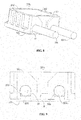
Figure 8 is a schematic structural perspective view of the temperature measuring device ofFigure 4 provided with a filling component. -
Figure 9 is a schematic projection view of the temperature measuring device ofFigure 8 . - The present disclosure will be described below in detail with reference to the accompanying drawings.
- With reference to
Figures 1 and 2 , the present disclosure provides a heatconductive assembly 101. The heatconductive assembly 101 may be adapted to transfer heat of an object to be measured (not shown in the figure) to atemperature measuring component 200. The heatconductive assembly 101 may comprise a thermallyconductive substrate 10. An electricallyconductive layer 30 may be disposed on anupper surface 10a of the thermallyconductive substrate 10. - The thermally
conductive substrate 10 has theupper surface 10a and alower surface 10b. Thelower surface 10b of the thermallyconductive substrate 10 may be adapted to be in contact with the object to be measured. The thermallyconductive substrate 10 may be adapted to transfer heat of the object to be measured to the electricallyconductive layer 30. The specific shape and configuration of the thermallyconductive substrate 10 may be selected as required. To improve the universality and facilitate the sensing of the stability of an electronic part, the thermallyconductive substrate 10 may be configured to be made from electrically insulating materials. To improve the heat conductive performance of the thermallyconductive substrate 10, the thermallyconductive substrate 10 may be a ceramic plate. More specifically, the thermallyconductive substrate 10 may be aluminum nitride (with a chemical formula: AlN). Accordingly, the thermallyconductive substrate 10 can greatly increase the heat conduction speed, thereby shortening the response time of thetemperature measuring component 200. To improve the stability of the connection between the thermallyconductive substrate 10 and the electricallyconductive layer 30, and increase the heat conduction speed, theupper surface 10a of the thermallyconductive substrate 10 may be provided with a recess. In other words, theupper surface 10a of the thermallyconductive substrate 10 has a degree of roughness. As a preferred embodiment, the thermallyconductive substrate 10 has such a uniform and consistent thickness that all of the mass-produced thermallyconductive substrates 10 can be ensured to be consistent in the heat conductive performance, so that the temperature measuring performance can be ensured to be consistent whenever the electricallyconductive layer 30 comes into contact with any part of theupper surface 10a of the thermallyconductive substrate 10. - The electrically
conductive layer 30 may be adapted to achieve an electrical connection between thetemperature measuring component 200 and aconnector 204, and to transfer heat to thetemperature measuring component 200. The electricallyconductive layer 30 may be fixedly disposed on theupper surface 10a of the thermallyconductive substrate 10. Accordingly, the electricallyconductive layer 30 may be disposed to be inseparable from the thermallyconductive substrate 10. The electricallyconductive layer 30 may comprise a supportingconnection portion 32 and anoutput connection portion 34 connected to each other. The supportingconnection portion 32 may be adapted to support thetemperature measuring component 200. The supportingconnection portion 32 may be in direct contact with thetemperature measuring component 200, and may be in electrically conductive and thermally conductive connection therewith. The specific shape and configuration of the supportingconnection portion 32 are only required to be able to achieve corresponding supporting. In this embodiment, to increase the contact area between the supportingconnection portion 32 and theupper surface 10a of the thermallyconductive substrate 10, the supportingconnection portion 32 may be substantially plate-shaped. To maximize material saving and increase the heat conduction speed, the shape of the supportingconnection portion 32 may be substantially identical to that of the bottom surface of thetemperature measuring component 200. Specifically, the supportingconnection portion 32 may be rectangular-shaped. In this embodiment, to save materials and reduce the substance required to be heated to a sensed temperature to increase the heat conduction speed, a pair of supportingconnection portions temperature measuring component 200. - The
output connection portion 34 may be connected with the supportingconnection portion 32. Further, to improve the heat conductive performance, the electricallyconductive layer 30 may be an integrated unit. Theoutput connection portion 34 may be adapted to output a signal sensed by thetemperature measuring component 200 to aconnector 204 described below. The specific shape and configuration of theoutput connection portion 34 are only required to be able to achieve a corresponding electrical connection. Preferably, to increase the heat conduction speed of theconductive layer 30, theoutput connection portion 34 may be disposed to be in contact with theupper surface 10a of the thermallyconductive substrate 10. To sufficiently reduce the volume of theoutput connection portion 34 so as to increase the heat conduction speed, and to ensure the stability of the connection between theoutput connection portion 34 and acorresponding connector 200, theoutput connection portion 34 may be substantially rectangular plate-shaped. In this embodiment, to facilitate transmission of corresponding signals, a pair ofoutput connection portions connectors - A
connection arm 36 may be connectively arranged between theoutput connection portion 34 and the supportingconnection portion 32, such that there is sufficient space between thetemperature measuring component 200 and the connector 205. Two ends of theconnection arm 36 may be connected with theoutput connection portion 34 and the supportingconnection portion 32, respectively. The specific shape and configuration of theconnection arm 36 are only required to be able to achieve a corresponding electrical connection. Specifically, theconnection arm 36 may be substantially plate-shaped. To increase the heat conduction speed, theconnection arm 36 may have a volume smaller than those of theoutput connection portion 34 and the supportingconnection portion 32. In this embodiment, theconnection arm 36 connects correspondingly theoutput connection portion 34 with the supportingconnection portion 32; aconnection arm 36b connects correspondingly theoutput connection portion 34b with the supportingconnection portion 32b. Preferably, theconnection arm 36, theoutput connection portion 34 and the supportingconnection portion 32 are connected together to form an integrated structure. Theconnection arm 36b, theoutput connection portion 34b and the supportingconnection portion 32b are connected together to form another integrated structure. - The electrically
conductive layer 30 may be manufactured from any electrically conductive materials. In this embodiment, the electricallyconductive layer 30 is made from metal materials. For example, the electricallyconductive layer 30 may be formed by copper or aluminum materials. To improve the stability of the connection between the electricallyconductive layer 30 and the thermallyconductive substrate 10 and increase the heat conduction speed, the electricallyconductive layer 30 may be a physical vapor deposition (PVD for short) structure. In other words, the electricallyconductive layer 30 may be connected integrally with theupper surface 10a of the thermallyconductive substrate 10 by means of physical vapor deposition. As another preferred embodiment, the electricallyconductive layer 30 may be a metal screen printed structure. In other words, the electricallyconductive layer 30 may be formed by applying a metal slurry to theupper surface 10a of the thermallyconductive substrate 10 by means of screen printing and forming a corresponding solidified structure. As yet another preferred embodiment, the electricallyconductive layer 30 may be a metal slurry solidified structure. In other words, the electricallyconductive layer 30 may be formed by applying a slurry-like metal material to theupper surface 10a of the thermallyconductive substrate 10 and connecting integrally with theupper surface 10a of the thermallyconductive substrate 10 by solidification. When required, the metal slurry may be formed into a solidified structure by means of high-temperature sintering. As a preferred embodiment, the electricallyconductive layer 30 has such a uniform and consistent thickness that the temperature measuring performance can be ensured to be consistent whenever thetemperature measuring component 30 comes into contact with any part of the upper surface of the electricallyconductive layer 30. To increase the heat conduction speed, the electricallyconductive layer 30 may have a thickness smaller than that of the thermallyconductive substrate 10. - With reference to
Figure 2 , to further reduce thermal and electrical resistances so as to increase the response speed of thetemperature measuring component 200, the present disclosure provides a heatconductive assembly 101b. As compared with Embodiment 1, the heatconductive assembly 101b also comprises ametal connection layer 50. Themetal connection layer 50 is disposed on the electricallyconductive layer 30. - The
metal connection layer 50 may be adapted to be in a direct contact electrical connection to thetemperature measuring component 200, and to transfer heat. Preferably, to further increase the response speed of thetemperature measuring component 200, themetal connection layer 50 may have a smaller thermal and/or electrical resistance than the electricallyconductive layer 30. Further, to improve the stability of the connection between themetal connection layer 50 and the electricallyconductive layer 30, and increase the heat conduction speed, themetal connection layer 50 may be a metal plating layer. In other words, themetal connection layer 50 may be a metallic electrically conductive structure laid onto the electricallyconductive layer 30 by means of metal plating. To improve corrosion resistance, themetal connection layer 50 may be made from metal materials such as gold or silver, etc. - With reference to
Figure 3 , the present disclosure also provides atemperature measuring device 301. Thetemperature measuring device 301 comprises the heatconductive assembly 101 as recited above in Embodiment 1 and atemperature measuring component 200. Thetemperature measuring component 200 may be disposed on the heatconductive assembly 101 to sense the temperature of an object to be measured through the heat transferred by the heatconductive assembly 101. Further, the heat conductive assembly 101 (or 101b) may be disposed to be in thermally conductive contact with thetemperature measuring component 200. As a preferred embodiment, thetemperature measuring device 301 may be adapted to measure the temperature of a solid, and exhibit an extremely fast response speed. - The
temperature measuring component 200 may be disposed on anupper surface 10a of the thermallyconductive substrate 10. Thetemperature measuring component 200 may be electrically connected with the supportingconnection portion 32. Preferably, a portion of thetemperature measuring component 200 may be disposed on the supportingconnection portion 32, and also adapted to be in a contact electrical connection to the supportingconnection portion 32. Further, thetemperature measuring component 200 may be adapted to be in thermally conductive contact with the supportingconnection portion 32. Still further, thetemperature measuring component 200 may be fixedly connected with the supportingconnection portion 32. Specifically, thetemperature measuring component 200 may be connected with the supportingconnection portion 32 by means of welding. To sufficiently save space and facilitate assembly, thetemperature measuring component 200 may be a patch component. Based on requirements of temperature measurement, thetemperature measuring component 200 may be a thermistor. More specifically, thetemperature measuring component 200 may be a negative temperature coefficient (NTC for short) thermistor or a positive temperature coefficient (PTC for short) thermistor. - With reference to
Figures 4 and5 , to facilitate improvements on the overall performance of thetemperature measuring device 301, the present disclosure provides yet anothertemperature measuring device 301b. As compared with the foregoingtemperature measuring device 301, thetemperature measuring device 301b also comprises a retaininghousing 202. - With reference to
Figures 6 and7 together, the retaininghousing 202 has achamber wall 221. Thechamber wall 221 encloses to form achamber 223. Specifically, thechamber wall 221 together with the thermallyconductive substrate 10 encloses thechamber 223. Thechamber 223 may be adapted to contain afilling component 206 described below. Thechamber 223 may be adapted to contain at least a portion of thetemperature measuring component 200. - To facilitate the mounting of the
filling component 206 described below, thechamber 223 may be a tubular chamber. In other words, thechamber 223 may extend through the retaininghousing 202 in a vertical direction. Accordingly, thechamber 223 may have atop opening 223a and abottom opening 223b that are formed on thechamber wall 221. Thetop opening 223a may be adapted to contain thefilling component 206 described below. Thebottom opening 223b may be adapted to contain a portion of the thermallyconductive substrate 10. - To further stably retain the thermally
conductive substrate 10, and facilitate the correct and rapid assembly of the thermallyconductive substrate 10, a limitinggroove 225 may be disposed on an inner surface of thechamber wall 221. The limitinggroove 225 may be adapted to contain and retain the thermallyconductive substrate 10 so that the thermallyconductive substrate 10 can also be prevented from completely falling down into thechamber 223. To further facilitate the correct and rapid assembly of the thermallyconductive substrate 10 into the limitinggroove 225, the limitinggroove 225 may be a rectangular groove. Accordingly, the thermallyconductive substrate 10 may be a rectangular plate. To further improve the stability of assembly of the thermallyconductive substrate 10 to the retaininghousing 202, the thermallyconductive substrate 10 may achieve an interference fit with the limitinggroove 225. In other words, the thermallyconductive substrate 10 may achieve an abutting fit with the groove wall of the limitinggroove 225. Based on application requirements, the thermallyconductive substrate 10 may also achieve an abutting fit with thechamber wall 221. - To improve the stability of retention of the
filling component 206 described below by the retaininghousing 202, and reduce the negative influence exerted on other parts by the fillingcomponent 206 as a result of deformation caused by changes in temperature difference, the retaininghousing 202 may also comprise areinforcement arm 227. Thereinforcement arm 227 may be disposed to extend from the inner surface of thechamber wall 221, to support thefilling component 206 and to enhance the overall strength of the retaininghousing 202. The specific shape and configuration of thereinforcement arm 227 may be selected as required. Further, both ends of thereinforcement arm 227 may be connected with the inner surface of thechamber wall 221. Preferably, thereinforcement arm 227 may separate thechamber 223 into at least two sub-chambers 224. The number and distribution of thereinforcement arm 227 may be selected as required. In this embodiment, fourreinforcement arms chamber 223 into threesub-chambers reinforcement arms chamber wall 221 enclose a sub-chamber 224 capable of surrounding thetemperature measuring component 200. Theother reinforcement arm 227d is connected with thereinforcement arm 227c and thechamber wall 221, respectively, thereby forming two separate sub-chambers 224b and 224c. The two sub-chambers 224b and 224c are "L"-shaped and symmetric to each other. To help fill thefilling component 206 described below, thesub-chambers - To facilitate the extension of the
connector 204 described below, thechamber wall 221 may be provided with a guiding through-hole 229. The guiding through-hole 229 may be disposed to extend through thechamber wall 221 and to be in communication with thechamber 223. In this embodiment, two guiding through-holes connectors - To help output the temperature signal sensed by the
temperature measuring component 200, thetemperature measuring device 101 may also comprise aconnector 204. Anend 241 of theconnector 204 may be adapted to be in a contact electrical connection to theoutput connection portion 34 so that a signal sensed by thetemperature measuring component 200 can be output. Specifically, theend 241 of theconnector 204 may be connected with theoutput connection portion 34 by means of welding. Accordingly, theend 241 of theconnector 204 may be fixedly connected with theoutput connection portion 34. Theother end 242 of theconnector 204 may be adapted to output a sensed signal sensed by thetemperature measuring component 200. The specific shape and specifications of theconnector 204 can be selected as required as long as a corresponding electrical connection can be achieved. In this embodiment, theconnector 204 may be a metal wire. Further, the metal wire may be an enamel-covered wire; alternatively, the metal wire may be provided with an insulating sheath to improve security. In this embodiment, the respective ends 241 and 241b of twoconnectors output connection portions connectors holes housing 202. - With reference to
Figures 8 and 9 , to improve the protection for corresponding devices within thechamber 223, the present disclosure further provides anothertemperature measuring device 301c. As compared with the foregoingtemperature measuring device 301b, thetemperature measuring device 301c also comprises afilling component 206. The fillingcomponent 206 is filled within thechamber 223 of the retaininghousing 202. The fillingcomponent 206 can provide protections such as electrical insulation and watertightness for thetemperature measuring component 200 and the heatconductive assembly 101. The specific material and specifications of thefilling component 206 are only required to enable corresponding filling. The fillingcomponent 206 may be a silicone cured structure. In other words, a corresponding integrated structure may be formed by injecting molten silicone into thechamber 223 and curing. In this embodiment, the fillingcomponent 206 is a photosensitive gel. The photosensitive gel (also referred to as UV gel) is a cured structure formed by irradiating by ultraviolet light. - It should be noted that the term "thickness" as used in the present disclosure refers to an extension dimension in a vertical direction, unless specifically indicated otherwise. In addition, the terms "upper, lower;" "left, right;" "front, rear;" and "one, another one" as used in the present disclosure all are relative concepts, and intended to facilitate understanding of relative positions of various parts with reference to the figures. Herein, the terms "upper, lower" may refer to the vertical direction as shown in
Figure 9 . - What have been described above are merely preferred embodiments of the present disclosure, and are not intended to limit the scope of the present disclosure. Any modifications, equivalents or improvements within the spirit of the present disclosure shall be covered by the scope of the claims of the present disclosure.
Claims (15)
- A heat conductive assembly for transferring heat of an object to be measured to a temperature measuring component, characterized in that: the heat conductive assembly comprises:a thermally conductive substrate having an upper surface and a lower surface, characterized in that the lower surface of the thermally conductive substrate is adapted to contact the object to be measured, andan electrically conductive layer fixedly disposed on the upper surface of the thermally conductive substrate; andthe electrically conductive layer comprises a supporting connection portion and an output connection portion connected to each other;the supporting connection portion is adapted to support the temperature measuring component and to be electrically connected to and be in thermally conductive contact with the temperature measuring component; andthe output connection portion is adapted to be electrically connected to a connector configured to output a signal sensed by the temperature measuring component.
- The heat conductive assembly of claim 1, characterized in that: the upper surface of the thermally conductive substrate has a recess; and a portion of the electrically conductive layer is filled into the recess.
- The heat conductive assembly of claim 1, characterized in that: the thermally conductive substrate is configured to be electrically insulating, or a ceramic plate.
- The heat conductive assembly of claim 1, characterized in that: the electrically conductive layer comprises at least one of a physical vapor deposited structure, a metal screen printed structure and a metal slurry solidified structure.
- The heat conductive assembly of any one of claims 1 to 4, characterized in that: it further comprises a metal connection layer disposed on the electrically conductive layer; and the electrically conductive layer and the metal connection layer are made from different metal materials.
- The heat conductive assembly of claim 5, characterized in that: the metal connection layer has a resistivity smaller than that of the electrically conductive layer.
- A temperature measuring device, characterized in that: it comprises the heat conductive assembly of any of claims 1 to 6 and a temperature measuring component disposed on the upper surface of the thermally conductive substrate and electrically connected with the supporting connection portion.
- The temperature measuring device of claim 7, characterized in that: the temperature measuring component is disposed to be in thermally conductive contact with the heat conductive assembly.
- The temperature measuring device of claim 7, characterized in that: it further comprises a connector, and an end of the connector is adapted to be in a contact electrical connection to the output connection portion and to output a signal sensed by the temperature measuring component.
- The temperature measuring device of claim 7, characterized in that: it further comprises a retaining housing having a chamber wall; the chamber wall together with the thermally conductive substrate encloses a chamber adapted to accommodate a filling component; and at least a portion of the temperature measuring component is disposed within the chamber.
- The temperature measuring device of claim 10, characterized in that: an inner surface of the chamber wall is provided with a limiting groove; and a portion of the thermally conductive substrate is contained within the limiting groove.
- The temperature measuring device of claim 10, characterized in that:the retaining housing is provided with a guiding through-hole;the guiding through-hole is disposed to extend through the chamber wall and to be in communication with the chamber; andthe temperature measuring device further comprises a connector, characterized in thatan end of the connector is adapted to pass through the guiding through-hole and to be in a contact electrical connection to the output connection portion; andanother end of the connector is adapted to output a signal sensed by the temperature measuring component.
- The temperature measuring device of claim 10, characterized in that: the retaining housing further comprises a reinforcement arm; and the reinforcement arm is disposed to extend from the inner surface of the chamber wall for supporting a filling component.
- The temperature measuring device of any one of claims 7 to 13, characterized in that: it further comprises a filling component adapted to be filled into the chamber.
- The temperature measuring device of claim 14, characterized in that: the filling component is a photosensitive gel cured structure or a silicone cured structure.
Applications Claiming Priority (1)
| Application Number | Priority Date | Filing Date | Title |
|---|---|---|---|
| CN201711145738.7A CN109798993B (en) | 2017-11-17 | 2017-11-17 | Thermal conductivity components and temperature measuring devices |
Publications (2)
| Publication Number | Publication Date |
|---|---|
| EP3486625A1 true EP3486625A1 (en) | 2019-05-22 |
| EP3486625B1 EP3486625B1 (en) | 2022-09-07 |
Family
ID=64316313
Family Applications (1)
| Application Number | Title | Priority Date | Filing Date |
|---|---|---|---|
| EP18206098.8A Active EP3486625B1 (en) | 2017-11-17 | 2018-11-14 | Heat conductive assembly and temperature measuring device |
Country Status (3)
| Country | Link |
|---|---|
| EP (1) | EP3486625B1 (en) |
| CN (1) | CN109798993B (en) |
| ES (1) | ES2928967T3 (en) |
Cited By (2)
| Publication number | Priority date | Publication date | Assignee | Title |
|---|---|---|---|---|
| CN110657894A (en) * | 2019-10-15 | 2020-01-07 | 日盈汽车电子(上海)有限公司 | Temperature detection device |
| CN115135977A (en) * | 2020-02-14 | 2022-09-30 | 施勒格尔塑料技术有限公司 | Device for determining the temperature of an object |
Families Citing this family (1)
| Publication number | Priority date | Publication date | Assignee | Title |
|---|---|---|---|---|
| CN114295241B (en) * | 2021-12-24 | 2026-01-23 | 昆山长盈精密技术有限公司 | Temperature sensing module |
Citations (2)
| Publication number | Priority date | Publication date | Assignee | Title |
|---|---|---|---|---|
| EP0547750A1 (en) * | 1991-12-19 | 1993-06-23 | Texas Instruments Incorporated | Temperature sensor |
| US6159386A (en) * | 1996-12-10 | 2000-12-12 | Heraeus Electro-Nite International N.V. | Electrical resistance with at least two contact fields on a ceramic substrate and process for manufacturing the same |
Family Cites Families (15)
| Publication number | Priority date | Publication date | Assignee | Title |
|---|---|---|---|---|
| GB881622A (en) * | 1958-06-30 | 1961-11-08 | Nat Res Dev | Improvements in or relating to temperature measuring devices |
| US4575705A (en) * | 1984-02-17 | 1986-03-11 | Weed Instrument Co., Inc. | Temperature probe |
| US7473030B2 (en) * | 2002-04-01 | 2009-01-06 | Palo Alto Research Center Incorporated | Thermal sensing |
| CN2922068Y (en) * | 2006-05-15 | 2007-07-11 | 奇鋐科技股份有限公司 | Radiator structure |
| TWI397200B (en) * | 2009-01-08 | 2013-05-21 | Chi Mei Lighting Tech Corp | Light-emitting diode device, and package structure and manufacturing method thereof |
| CN101858793B (en) * | 2010-05-22 | 2012-07-04 | 东方电气集团东方汽轮机有限公司 | Narrow gap weld seam temperature measuring device and method |
| FR2963674B1 (en) * | 2010-08-05 | 2013-05-17 | Astrium Sas | DEVICE FOR MEASURING THE TEMPERATURE OF A SUBSTRATE |
| TWM446327U (en) * | 2012-09-13 | 2013-02-01 | Thinking Electronic Ind Co Ltd | Temperature sensing device of contact type |
| CN202886007U (en) * | 2012-09-19 | 2013-04-17 | 兴勤电子工业股份有限公司 | Contact type temperature sensing device |
| KR101648421B1 (en) * | 2014-07-17 | 2016-08-16 | 한국산업기술시험원 | Function test apparatus for heat sink |
| CN106574875B (en) * | 2014-07-31 | 2019-11-05 | 株式会社村田制作所 | Temperature detection device and electronic apparatus |
| CN204924473U (en) * | 2015-08-05 | 2015-12-30 | 华帝股份有限公司 | Double-layer heat-insulation suspension type temperature sensor |
| CN206177474U (en) * | 2016-08-12 | 2017-05-17 | 泰科电子(上海)有限公司 | Thermometric component and electrical equipment |
| CN206274279U (en) * | 2016-12-23 | 2017-06-23 | 佛山市顺德区美的电热电器制造有限公司 | Temperature measurement component and heating pan for measuring the mean temperature of testee |
| CN207379622U (en) * | 2017-11-17 | 2018-05-18 | 泰科电子(上海)有限公司 | Heat conduction components and temperature measuring devices |
-
2017
- 2017-11-17 CN CN201711145738.7A patent/CN109798993B/en active Active
-
2018
- 2018-11-14 ES ES18206098T patent/ES2928967T3/en active Active
- 2018-11-14 EP EP18206098.8A patent/EP3486625B1/en active Active
Patent Citations (2)
| Publication number | Priority date | Publication date | Assignee | Title |
|---|---|---|---|---|
| EP0547750A1 (en) * | 1991-12-19 | 1993-06-23 | Texas Instruments Incorporated | Temperature sensor |
| US6159386A (en) * | 1996-12-10 | 2000-12-12 | Heraeus Electro-Nite International N.V. | Electrical resistance with at least two contact fields on a ceramic substrate and process for manufacturing the same |
Cited By (2)
| Publication number | Priority date | Publication date | Assignee | Title |
|---|---|---|---|---|
| CN110657894A (en) * | 2019-10-15 | 2020-01-07 | 日盈汽车电子(上海)有限公司 | Temperature detection device |
| CN115135977A (en) * | 2020-02-14 | 2022-09-30 | 施勒格尔塑料技术有限公司 | Device for determining the temperature of an object |
Also Published As
| Publication number | Publication date |
|---|---|
| ES2928967T3 (en) | 2022-11-24 |
| CN109798993B (en) | 2024-09-27 |
| EP3486625B1 (en) | 2022-09-07 |
| CN109798993A (en) | 2019-05-24 |
Similar Documents
| Publication | Publication Date | Title |
|---|---|---|
| EP3486625B1 (en) | Heat conductive assembly and temperature measuring device | |
| US8935843B2 (en) | Temperature sensor and method for its manufacture | |
| CN206332954U (en) | Electric appliance component | |
| JP4935225B2 (en) | Electronic component assembly | |
| TW379336B (en) | Surface mountable electronic devices | |
| EP0547750A1 (en) | Temperature sensor | |
| CN109073473A (en) | temperature sensor | |
| JP5766348B2 (en) | Tubular heater | |
| WO2013118481A1 (en) | Infrared sensor and infrared sensor device | |
| US8529127B2 (en) | Construction and manufacturing method for a sensor of a thermal flow measuring device | |
| KR101624105B1 (en) | Terminal block for temperature compensating of thermocouple | |
| CN207379622U (en) | Heat conduction components and temperature measuring devices | |
| US20200149974A1 (en) | Contact Temperature Sensor | |
| US20030127445A1 (en) | Heater for heating waveguide and waveguide with heater | |
| CN212254416U (en) | Glass liner temperature sensing probe mounting structure capable of rapidly and accurately sensing temperature | |
| CN104602445B (en) | A kind of direct insertion terminal suitable for aluminum base circuit board | |
| JP7274676B1 (en) | temperature sensor | |
| CN215893803U (en) | Battery pack temperature sensor | |
| US20200080896A1 (en) | Infrared sensor mounting member | |
| US20120093192A1 (en) | Method and measuring sensor for temperature measurement | |
| CN109640407A (en) | A kind of plate thick film heater and manufacturing process | |
| CN209559346U (en) | Components, measuring devices for measuring the case temperature of discrete components | |
| ITMI942547A1 (en) | HEATING DEVICE FOR VAPORIZERS OF INSECTICIDES OR PERFUMES IN SOLID OR LIQUID FORMULATIONS | |
| CN216353612U (en) | Cement resistance | |
| CN210774410U (en) | Temperature sensor and electronic device |
Legal Events
| Date | Code | Title | Description |
|---|---|---|---|
| PUAI | Public reference made under article 153(3) epc to a published international application that has entered the european phase |
Free format text: ORIGINAL CODE: 0009012 |
|
| STAA | Information on the status of an ep patent application or granted ep patent |
Free format text: STATUS: THE APPLICATION HAS BEEN PUBLISHED |
|
| AK | Designated contracting states |
Kind code of ref document: A1 Designated state(s): AL AT BE BG CH CY CZ DE DK EE ES FI FR GB GR HR HU IE IS IT LI LT LU LV MC MK MT NL NO PL PT RO RS SE SI SK SM TR |
|
| AX | Request for extension of the european patent |
Extension state: BA ME |
|
| STAA | Information on the status of an ep patent application or granted ep patent |
Free format text: STATUS: REQUEST FOR EXAMINATION WAS MADE |
|
| 17P | Request for examination filed |
Effective date: 20191122 |
|
| RBV | Designated contracting states (corrected) |
Designated state(s): AL AT BE BG CH CY CZ DE DK EE ES FI FR GB GR HR HU IE IS IT LI LT LU LV MC MK MT NL NO PL PT RO RS SE SI SK SM TR |
|
| STAA | Information on the status of an ep patent application or granted ep patent |
Free format text: STATUS: EXAMINATION IS IN PROGRESS |
|
| 17Q | First examination report despatched |
Effective date: 20200814 |
|
| GRAP | Despatch of communication of intention to grant a patent |
Free format text: ORIGINAL CODE: EPIDOSNIGR1 |
|
| STAA | Information on the status of an ep patent application or granted ep patent |
Free format text: STATUS: GRANT OF PATENT IS INTENDED |
|
| INTG | Intention to grant announced |
Effective date: 20220406 |
|
| GRAS | Grant fee paid |
Free format text: ORIGINAL CODE: EPIDOSNIGR3 |
|
| GRAA | (expected) grant |
Free format text: ORIGINAL CODE: 0009210 |
|
| STAA | Information on the status of an ep patent application or granted ep patent |
Free format text: STATUS: THE PATENT HAS BEEN GRANTED |
|
| AK | Designated contracting states |
Kind code of ref document: B1 Designated state(s): AL AT BE BG CH CY CZ DE DK EE ES FI FR GB GR HR HU IE IS IT LI LT LU LV MC MK MT NL NO PL PT RO RS SE SI SK SM TR |
|
| REG | Reference to a national code |
Ref country code: GB Ref legal event code: FG4D |
|
| REG | Reference to a national code |
Ref country code: CH Ref legal event code: EP Ref country code: AT Ref legal event code: REF Ref document number: 1517422 Country of ref document: AT Kind code of ref document: T Effective date: 20220915 |
|
| REG | Reference to a national code |
Ref country code: DE Ref legal event code: R096 Ref document number: 602018040267 Country of ref document: DE |
|
| REG | Reference to a national code |
Ref country code: IE Ref legal event code: FG4D |
|
| REG | Reference to a national code |
Ref country code: ES Ref legal event code: FG2A Ref document number: 2928967 Country of ref document: ES Kind code of ref document: T3 Effective date: 20221124 |
|
| REG | Reference to a national code |
Ref country code: LT Ref legal event code: MG9D |
|
| REG | Reference to a national code |
Ref country code: NL Ref legal event code: MP Effective date: 20220907 |
|
| PG25 | Lapsed in a contracting state [announced via postgrant information from national office to epo] |
Ref country code: SE Free format text: LAPSE BECAUSE OF FAILURE TO SUBMIT A TRANSLATION OF THE DESCRIPTION OR TO PAY THE FEE WITHIN THE PRESCRIBED TIME-LIMIT Effective date: 20220907 Ref country code: RS Free format text: LAPSE BECAUSE OF FAILURE TO SUBMIT A TRANSLATION OF THE DESCRIPTION OR TO PAY THE FEE WITHIN THE PRESCRIBED TIME-LIMIT Effective date: 20220907 Ref country code: NO Free format text: LAPSE BECAUSE OF FAILURE TO SUBMIT A TRANSLATION OF THE DESCRIPTION OR TO PAY THE FEE WITHIN THE PRESCRIBED TIME-LIMIT Effective date: 20221207 Ref country code: LV Free format text: LAPSE BECAUSE OF FAILURE TO SUBMIT A TRANSLATION OF THE DESCRIPTION OR TO PAY THE FEE WITHIN THE PRESCRIBED TIME-LIMIT Effective date: 20220907 Ref country code: LT Free format text: LAPSE BECAUSE OF FAILURE TO SUBMIT A TRANSLATION OF THE DESCRIPTION OR TO PAY THE FEE WITHIN THE PRESCRIBED TIME-LIMIT Effective date: 20220907 Ref country code: FI Free format text: LAPSE BECAUSE OF FAILURE TO SUBMIT A TRANSLATION OF THE DESCRIPTION OR TO PAY THE FEE WITHIN THE PRESCRIBED TIME-LIMIT Effective date: 20220907 |
|
| REG | Reference to a national code |
Ref country code: AT Ref legal event code: MK05 Ref document number: 1517422 Country of ref document: AT Kind code of ref document: T Effective date: 20220907 |
|
| PG25 | Lapsed in a contracting state [announced via postgrant information from national office to epo] |
Ref country code: HR Free format text: LAPSE BECAUSE OF FAILURE TO SUBMIT A TRANSLATION OF THE DESCRIPTION OR TO PAY THE FEE WITHIN THE PRESCRIBED TIME-LIMIT Effective date: 20220907 Ref country code: GR Free format text: LAPSE BECAUSE OF FAILURE TO SUBMIT A TRANSLATION OF THE DESCRIPTION OR TO PAY THE FEE WITHIN THE PRESCRIBED TIME-LIMIT Effective date: 20221208 |
|
| PG25 | Lapsed in a contracting state [announced via postgrant information from national office to epo] |
Ref country code: SM Free format text: LAPSE BECAUSE OF FAILURE TO SUBMIT A TRANSLATION OF THE DESCRIPTION OR TO PAY THE FEE WITHIN THE PRESCRIBED TIME-LIMIT Effective date: 20220907 Ref country code: RO Free format text: LAPSE BECAUSE OF FAILURE TO SUBMIT A TRANSLATION OF THE DESCRIPTION OR TO PAY THE FEE WITHIN THE PRESCRIBED TIME-LIMIT Effective date: 20220907 Ref country code: PT Free format text: LAPSE BECAUSE OF FAILURE TO SUBMIT A TRANSLATION OF THE DESCRIPTION OR TO PAY THE FEE WITHIN THE PRESCRIBED TIME-LIMIT Effective date: 20230109 Ref country code: CZ Free format text: LAPSE BECAUSE OF FAILURE TO SUBMIT A TRANSLATION OF THE DESCRIPTION OR TO PAY THE FEE WITHIN THE PRESCRIBED TIME-LIMIT Effective date: 20220907 Ref country code: AT Free format text: LAPSE BECAUSE OF FAILURE TO SUBMIT A TRANSLATION OF THE DESCRIPTION OR TO PAY THE FEE WITHIN THE PRESCRIBED TIME-LIMIT Effective date: 20220907 |
|
| PG25 | Lapsed in a contracting state [announced via postgrant information from national office to epo] |
Ref country code: SK Free format text: LAPSE BECAUSE OF FAILURE TO SUBMIT A TRANSLATION OF THE DESCRIPTION OR TO PAY THE FEE WITHIN THE PRESCRIBED TIME-LIMIT Effective date: 20220907 Ref country code: PL Free format text: LAPSE BECAUSE OF FAILURE TO SUBMIT A TRANSLATION OF THE DESCRIPTION OR TO PAY THE FEE WITHIN THE PRESCRIBED TIME-LIMIT Effective date: 20220907 Ref country code: IS Free format text: LAPSE BECAUSE OF FAILURE TO SUBMIT A TRANSLATION OF THE DESCRIPTION OR TO PAY THE FEE WITHIN THE PRESCRIBED TIME-LIMIT Effective date: 20230107 Ref country code: EE Free format text: LAPSE BECAUSE OF FAILURE TO SUBMIT A TRANSLATION OF THE DESCRIPTION OR TO PAY THE FEE WITHIN THE PRESCRIBED TIME-LIMIT Effective date: 20220907 |
|
| REG | Reference to a national code |
Ref country code: DE Ref legal event code: R097 Ref document number: 602018040267 Country of ref document: DE |
|
| PG25 | Lapsed in a contracting state [announced via postgrant information from national office to epo] |
Ref country code: NL Free format text: LAPSE BECAUSE OF FAILURE TO SUBMIT A TRANSLATION OF THE DESCRIPTION OR TO PAY THE FEE WITHIN THE PRESCRIBED TIME-LIMIT Effective date: 20220907 Ref country code: MC Free format text: LAPSE BECAUSE OF FAILURE TO SUBMIT A TRANSLATION OF THE DESCRIPTION OR TO PAY THE FEE WITHIN THE PRESCRIBED TIME-LIMIT Effective date: 20220907 Ref country code: AL Free format text: LAPSE BECAUSE OF FAILURE TO SUBMIT A TRANSLATION OF THE DESCRIPTION OR TO PAY THE FEE WITHIN THE PRESCRIBED TIME-LIMIT Effective date: 20220907 |
|
| REG | Reference to a national code |
Ref country code: CH Ref legal event code: PL |
|
| PLBE | No opposition filed within time limit |
Free format text: ORIGINAL CODE: 0009261 |
|
| STAA | Information on the status of an ep patent application or granted ep patent |
Free format text: STATUS: NO OPPOSITION FILED WITHIN TIME LIMIT |
|
| REG | Reference to a national code |
Ref country code: BE Ref legal event code: MM Effective date: 20221130 |
|
| PG25 | Lapsed in a contracting state [announced via postgrant information from national office to epo] |
Ref country code: LI Free format text: LAPSE BECAUSE OF NON-PAYMENT OF DUE FEES Effective date: 20221130 Ref country code: DK Free format text: LAPSE BECAUSE OF FAILURE TO SUBMIT A TRANSLATION OF THE DESCRIPTION OR TO PAY THE FEE WITHIN THE PRESCRIBED TIME-LIMIT Effective date: 20220907 Ref country code: CH Free format text: LAPSE BECAUSE OF NON-PAYMENT OF DUE FEES Effective date: 20221130 |
|
| 26N | No opposition filed |
Effective date: 20230608 |
|
| GBPC | Gb: european patent ceased through non-payment of renewal fee |
Effective date: 20221207 |
|
| PG25 | Lapsed in a contracting state [announced via postgrant information from national office to epo] |
Ref country code: SI Free format text: LAPSE BECAUSE OF FAILURE TO SUBMIT A TRANSLATION OF THE DESCRIPTION OR TO PAY THE FEE WITHIN THE PRESCRIBED TIME-LIMIT Effective date: 20220907 Ref country code: LU Free format text: LAPSE BECAUSE OF NON-PAYMENT OF DUE FEES Effective date: 20221114 |
|
| PG25 | Lapsed in a contracting state [announced via postgrant information from national office to epo] |
Ref country code: IE Free format text: LAPSE BECAUSE OF NON-PAYMENT OF DUE FEES Effective date: 20221114 Ref country code: GB Free format text: LAPSE BECAUSE OF NON-PAYMENT OF DUE FEES Effective date: 20221207 |
|
| PG25 | Lapsed in a contracting state [announced via postgrant information from national office to epo] |
Ref country code: BE Free format text: LAPSE BECAUSE OF NON-PAYMENT OF DUE FEES Effective date: 20221130 |
|
| PG25 | Lapsed in a contracting state [announced via postgrant information from national office to epo] |
Ref country code: HU Free format text: LAPSE BECAUSE OF FAILURE TO SUBMIT A TRANSLATION OF THE DESCRIPTION OR TO PAY THE FEE WITHIN THE PRESCRIBED TIME-LIMIT; INVALID AB INITIO Effective date: 20181114 |
|
| PG25 | Lapsed in a contracting state [announced via postgrant information from national office to epo] |
Ref country code: CY Free format text: LAPSE BECAUSE OF FAILURE TO SUBMIT A TRANSLATION OF THE DESCRIPTION OR TO PAY THE FEE WITHIN THE PRESCRIBED TIME-LIMIT Effective date: 20220907 |
|
| PG25 | Lapsed in a contracting state [announced via postgrant information from national office to epo] |
Ref country code: MK Free format text: LAPSE BECAUSE OF FAILURE TO SUBMIT A TRANSLATION OF THE DESCRIPTION OR TO PAY THE FEE WITHIN THE PRESCRIBED TIME-LIMIT Effective date: 20220907 |
|
| PG25 | Lapsed in a contracting state [announced via postgrant information from national office to epo] |
Ref country code: BG Free format text: LAPSE BECAUSE OF FAILURE TO SUBMIT A TRANSLATION OF THE DESCRIPTION OR TO PAY THE FEE WITHIN THE PRESCRIBED TIME-LIMIT Effective date: 20220907 |
|
| PG25 | Lapsed in a contracting state [announced via postgrant information from national office to epo] |
Ref country code: MT Free format text: LAPSE BECAUSE OF FAILURE TO SUBMIT A TRANSLATION OF THE DESCRIPTION OR TO PAY THE FEE WITHIN THE PRESCRIBED TIME-LIMIT Effective date: 20220907 |
|
| PGFP | Annual fee paid to national office [announced via postgrant information from national office to epo] |
Ref country code: FR Payment date: 20240909 Year of fee payment: 7 |
|
| PGFP | Annual fee paid to national office [announced via postgrant information from national office to epo] |
Ref country code: IT Payment date: 20241010 Year of fee payment: 7 Ref country code: ES Payment date: 20241206 Year of fee payment: 7 |
|
| PG25 | Lapsed in a contracting state [announced via postgrant information from national office to epo] |
Ref country code: TR Free format text: LAPSE BECAUSE OF FAILURE TO SUBMIT A TRANSLATION OF THE DESCRIPTION OR TO PAY THE FEE WITHIN THE PRESCRIBED TIME-LIMIT Effective date: 20220907 |
|
| PGFP | Annual fee paid to national office [announced via postgrant information from national office to epo] |
Ref country code: DE Payment date: 20250916 Year of fee payment: 8 |