EP3486499B1 - Cooler ventilation module - Google Patents
Cooler ventilation module Download PDFInfo
- Publication number
- EP3486499B1 EP3486499B1 EP18204663.1A EP18204663A EP3486499B1 EP 3486499 B1 EP3486499 B1 EP 3486499B1 EP 18204663 A EP18204663 A EP 18204663A EP 3486499 B1 EP3486499 B1 EP 3486499B1
- Authority
- EP
- European Patent Office
- Prior art keywords
- struts
- strut
- cooling fan
- fan module
- motor
- Prior art date
- Legal status (The legal status is an assumption and is not a legal conclusion. Google has not performed a legal analysis and makes no representation as to the accuracy of the status listed.)
- Active
Links
- 238000009423 ventilation Methods 0.000 title 1
- 238000001816 cooling Methods 0.000 claims description 35
- 230000002787 reinforcement Effects 0.000 claims description 20
- 229920003023 plastic Polymers 0.000 claims description 7
- 239000004033 plastic Substances 0.000 claims description 7
- 238000002347 injection Methods 0.000 claims description 2
- 239000007924 injection Substances 0.000 claims description 2
- 238000005728 strengthening Methods 0.000 claims 1
- 238000013461 design Methods 0.000 description 8
- 238000002485 combustion reaction Methods 0.000 description 6
- 239000002826 coolant Substances 0.000 description 6
- 238000011161 development Methods 0.000 description 6
- 230000018109 developmental process Effects 0.000 description 6
- 238000010586 diagram Methods 0.000 description 5
- 230000000694 effects Effects 0.000 description 5
- 238000011144 upstream manufacturing Methods 0.000 description 5
- 238000012937 correction Methods 0.000 description 4
- 239000000463 material Substances 0.000 description 4
- 229910000831 Steel Inorganic materials 0.000 description 3
- 229910052782 aluminium Inorganic materials 0.000 description 3
- XAGFODPZIPBFFR-UHFFFAOYSA-N aluminium Chemical compound [Al] XAGFODPZIPBFFR-UHFFFAOYSA-N 0.000 description 3
- 230000005855 radiation Effects 0.000 description 3
- 239000010959 steel Substances 0.000 description 3
- 238000012360 testing method Methods 0.000 description 3
- XEEYBQQBJWHFJM-UHFFFAOYSA-N Iron Chemical compound [Fe] XEEYBQQBJWHFJM-UHFFFAOYSA-N 0.000 description 2
- 238000009825 accumulation Methods 0.000 description 2
- 238000009434 installation Methods 0.000 description 2
- 229910052751 metal Inorganic materials 0.000 description 2
- 239000002184 metal Substances 0.000 description 2
- 239000000126 substance Substances 0.000 description 2
- 238000010408 sweeping Methods 0.000 description 2
- 230000007704 transition Effects 0.000 description 2
- 241001136792 Alle Species 0.000 description 1
- 229910001369 Brass Inorganic materials 0.000 description 1
- FYYHWMGAXLPEAU-UHFFFAOYSA-N Magnesium Chemical compound [Mg] FYYHWMGAXLPEAU-UHFFFAOYSA-N 0.000 description 1
- 238000007792 addition Methods 0.000 description 1
- 230000002528 anti-freeze Effects 0.000 description 1
- 230000009286 beneficial effect Effects 0.000 description 1
- 230000000903 blocking effect Effects 0.000 description 1
- 239000010951 brass Substances 0.000 description 1
- 230000008859 change Effects 0.000 description 1
- 150000001875 compounds Chemical class 0.000 description 1
- 230000007797 corrosion Effects 0.000 description 1
- 238000005260 corrosion Methods 0.000 description 1
- 239000012530 fluid Substances 0.000 description 1
- 230000006870 function Effects 0.000 description 1
- 230000001771 impaired effect Effects 0.000 description 1
- 239000003112 inhibitor Substances 0.000 description 1
- 238000011835 investigation Methods 0.000 description 1
- 229910052742 iron Inorganic materials 0.000 description 1
- 230000001050 lubricating effect Effects 0.000 description 1
- 229910052749 magnesium Inorganic materials 0.000 description 1
- 239000011777 magnesium Substances 0.000 description 1
- 230000000873 masking effect Effects 0.000 description 1
- 239000007769 metal material Substances 0.000 description 1
- 238000000034 method Methods 0.000 description 1
- 239000000203 mixture Substances 0.000 description 1
- 230000008447 perception Effects 0.000 description 1
- 230000008092 positive effect Effects 0.000 description 1
- 230000008569 process Effects 0.000 description 1
- 230000009467 reduction Effects 0.000 description 1
- 230000003014 reinforcing effect Effects 0.000 description 1
- 230000008646 thermal stress Effects 0.000 description 1
- XLYOFNOQVPJJNP-UHFFFAOYSA-N water Substances O XLYOFNOQVPJJNP-UHFFFAOYSA-N 0.000 description 1
Images


Classifications
-
- F—MECHANICAL ENGINEERING; LIGHTING; HEATING; WEAPONS; BLASTING
- F01—MACHINES OR ENGINES IN GENERAL; ENGINE PLANTS IN GENERAL; STEAM ENGINES
- F01P—COOLING OF MACHINES OR ENGINES IN GENERAL; COOLING OF INTERNAL-COMBUSTION ENGINES
- F01P5/00—Pumping cooling-air or liquid coolants
- F01P5/02—Pumping cooling-air; Arrangements of cooling-air pumps, e.g. fans or blowers
- F01P5/06—Guiding or ducting air to, or from, ducted fans
-
- F—MECHANICAL ENGINEERING; LIGHTING; HEATING; WEAPONS; BLASTING
- F01—MACHINES OR ENGINES IN GENERAL; ENGINE PLANTS IN GENERAL; STEAM ENGINES
- F01D—NON-POSITIVE DISPLACEMENT MACHINES OR ENGINES, e.g. STEAM TURBINES
- F01D5/00—Blades; Blade-carrying members; Heating, heat-insulating, cooling or antivibration means on the blades or the members
- F01D5/12—Blades
- F01D5/14—Form or construction
- F01D5/141—Shape, i.e. outer, aerodynamic form
-
- F—MECHANICAL ENGINEERING; LIGHTING; HEATING; WEAPONS; BLASTING
- F04—POSITIVE - DISPLACEMENT MACHINES FOR LIQUIDS; PUMPS FOR LIQUIDS OR ELASTIC FLUIDS
- F04D—NON-POSITIVE-DISPLACEMENT PUMPS
- F04D29/00—Details, component parts, or accessories
- F04D29/66—Combating cavitation, whirls, noise, vibration or the like; Balancing
- F04D29/661—Combating cavitation, whirls, noise, vibration or the like; Balancing especially adapted for elastic fluid pumps
- F04D29/666—Combating cavitation, whirls, noise, vibration or the like; Balancing especially adapted for elastic fluid pumps by means of rotor construction or layout, e.g. unequal distribution of blades or vanes
-
- F—MECHANICAL ENGINEERING; LIGHTING; HEATING; WEAPONS; BLASTING
- F01—MACHINES OR ENGINES IN GENERAL; ENGINE PLANTS IN GENERAL; STEAM ENGINES
- F01P—COOLING OF MACHINES OR ENGINES IN GENERAL; COOLING OF INTERNAL-COMBUSTION ENGINES
- F01P5/00—Pumping cooling-air or liquid coolants
- F01P5/02—Pumping cooling-air; Arrangements of cooling-air pumps, e.g. fans or blowers
- F01P5/04—Pump-driving arrangements
-
- F—MECHANICAL ENGINEERING; LIGHTING; HEATING; WEAPONS; BLASTING
- F04—POSITIVE - DISPLACEMENT MACHINES FOR LIQUIDS; PUMPS FOR LIQUIDS OR ELASTIC FLUIDS
- F04D—NON-POSITIVE-DISPLACEMENT PUMPS
- F04D19/00—Axial-flow pumps
- F04D19/002—Axial flow fans
-
- F—MECHANICAL ENGINEERING; LIGHTING; HEATING; WEAPONS; BLASTING
- F04—POSITIVE - DISPLACEMENT MACHINES FOR LIQUIDS; PUMPS FOR LIQUIDS OR ELASTIC FLUIDS
- F04D—NON-POSITIVE-DISPLACEMENT PUMPS
- F04D29/00—Details, component parts, or accessories
- F04D29/18—Rotors
- F04D29/181—Axial flow rotors
-
- F—MECHANICAL ENGINEERING; LIGHTING; HEATING; WEAPONS; BLASTING
- F04—POSITIVE - DISPLACEMENT MACHINES FOR LIQUIDS; PUMPS FOR LIQUIDS OR ELASTIC FLUIDS
- F04D—NON-POSITIVE-DISPLACEMENT PUMPS
- F04D29/00—Details, component parts, or accessories
- F04D29/18—Rotors
- F04D29/22—Rotors specially for centrifugal pumps
- F04D29/24—Vanes
- F04D29/242—Geometry, shape
- F04D29/245—Geometry, shape for special effects
-
- F—MECHANICAL ENGINEERING; LIGHTING; HEATING; WEAPONS; BLASTING
- F04—POSITIVE - DISPLACEMENT MACHINES FOR LIQUIDS; PUMPS FOR LIQUIDS OR ELASTIC FLUIDS
- F04D—NON-POSITIVE-DISPLACEMENT PUMPS
- F04D29/00—Details, component parts, or accessories
- F04D29/26—Rotors specially for elastic fluids
- F04D29/32—Rotors specially for elastic fluids for axial flow pumps
- F04D29/325—Rotors specially for elastic fluids for axial flow pumps for axial flow fans
-
- F—MECHANICAL ENGINEERING; LIGHTING; HEATING; WEAPONS; BLASTING
- F04—POSITIVE - DISPLACEMENT MACHINES FOR LIQUIDS; PUMPS FOR LIQUIDS OR ELASTIC FLUIDS
- F04D—NON-POSITIVE-DISPLACEMENT PUMPS
- F04D29/00—Details, component parts, or accessories
- F04D29/26—Rotors specially for elastic fluids
- F04D29/32—Rotors specially for elastic fluids for axial flow pumps
- F04D29/38—Blades
- F04D29/384—Blades characterised by form
- F04D29/386—Skewed blades
-
- F—MECHANICAL ENGINEERING; LIGHTING; HEATING; WEAPONS; BLASTING
- F04—POSITIVE - DISPLACEMENT MACHINES FOR LIQUIDS; PUMPS FOR LIQUIDS OR ELASTIC FLUIDS
- F04D—NON-POSITIVE-DISPLACEMENT PUMPS
- F04D29/00—Details, component parts, or accessories
- F04D29/26—Rotors specially for elastic fluids
- F04D29/32—Rotors specially for elastic fluids for axial flow pumps
- F04D29/38—Blades
- F04D29/388—Blades characterised by construction
-
- F—MECHANICAL ENGINEERING; LIGHTING; HEATING; WEAPONS; BLASTING
- F04—POSITIVE - DISPLACEMENT MACHINES FOR LIQUIDS; PUMPS FOR LIQUIDS OR ELASTIC FLUIDS
- F04D—NON-POSITIVE-DISPLACEMENT PUMPS
- F04D29/00—Details, component parts, or accessories
- F04D29/40—Casings; Connections of working fluid
- F04D29/52—Casings; Connections of working fluid for axial pumps
- F04D29/54—Fluid-guiding means, e.g. diffusers
- F04D29/541—Specially adapted for elastic fluid pumps
- F04D29/542—Bladed diffusers
- F04D29/544—Blade shapes
-
- F—MECHANICAL ENGINEERING; LIGHTING; HEATING; WEAPONS; BLASTING
- F01—MACHINES OR ENGINES IN GENERAL; ENGINE PLANTS IN GENERAL; STEAM ENGINES
- F01P—COOLING OF MACHINES OR ENGINES IN GENERAL; COOLING OF INTERNAL-COMBUSTION ENGINES
- F01P11/00—Component parts, details, or accessories not provided for in, or of interest apart from, groups F01P1/00 - F01P9/00
- F01P11/10—Guiding or ducting cooling-air, to, or from, liquid-to-air heat exchangers
-
- F—MECHANICAL ENGINEERING; LIGHTING; HEATING; WEAPONS; BLASTING
- F01—MACHINES OR ENGINES IN GENERAL; ENGINE PLANTS IN GENERAL; STEAM ENGINES
- F01P—COOLING OF MACHINES OR ENGINES IN GENERAL; COOLING OF INTERNAL-COMBUSTION ENGINES
- F01P5/00—Pumping cooling-air or liquid coolants
- F01P5/02—Pumping cooling-air; Arrangements of cooling-air pumps, e.g. fans or blowers
- F01P5/04—Pump-driving arrangements
- F01P2005/046—Pump-driving arrangements with electrical pump drive
-
- F—MECHANICAL ENGINEERING; LIGHTING; HEATING; WEAPONS; BLASTING
- F01—MACHINES OR ENGINES IN GENERAL; ENGINE PLANTS IN GENERAL; STEAM ENGINES
- F01P—COOLING OF MACHINES OR ENGINES IN GENERAL; COOLING OF INTERNAL-COMBUSTION ENGINES
- F01P2070/00—Details
- F01P2070/50—Details mounting fans to heat-exchangers
-
- F—MECHANICAL ENGINEERING; LIGHTING; HEATING; WEAPONS; BLASTING
- F04—POSITIVE - DISPLACEMENT MACHINES FOR LIQUIDS; PUMPS FOR LIQUIDS OR ELASTIC FLUIDS
- F04D—NON-POSITIVE-DISPLACEMENT PUMPS
- F04D29/00—Details, component parts, or accessories
- F04D29/002—Details, component parts, or accessories especially adapted for elastic fluid pumps
-
- F—MECHANICAL ENGINEERING; LIGHTING; HEATING; WEAPONS; BLASTING
- F04—POSITIVE - DISPLACEMENT MACHINES FOR LIQUIDS; PUMPS FOR LIQUIDS OR ELASTIC FLUIDS
- F04D—NON-POSITIVE-DISPLACEMENT PUMPS
- F04D29/00—Details, component parts, or accessories
- F04D29/26—Rotors specially for elastic fluids
- F04D29/263—Rotors specially for elastic fluids mounting fan or blower rotors on shafts
-
- F—MECHANICAL ENGINEERING; LIGHTING; HEATING; WEAPONS; BLASTING
- F04—POSITIVE - DISPLACEMENT MACHINES FOR LIQUIDS; PUMPS FOR LIQUIDS OR ELASTIC FLUIDS
- F04D—NON-POSITIVE-DISPLACEMENT PUMPS
- F04D29/00—Details, component parts, or accessories
- F04D29/60—Mounting; Assembling; Disassembling
- F04D29/64—Mounting; Assembling; Disassembling of axial pumps
- F04D29/644—Mounting; Assembling; Disassembling of axial pumps especially adapted for elastic fluid pumps
Definitions
- the present invention relates to a radiator fan module, in particular an electrically operated radiator fan module, in particular for motor vehicles, with struts located at the rear as seen in the main flow direction.
- the cooling system in an internal combustion engine mainly removes the heat that is released to the walls of the combustion chamber and cylinder because the combustion process is not ideal. Since temperatures that are too high would damage the engine (tearing off the lubricating film, burning the valves, etc.), the internal combustion engine must be actively cooled.
- the coolant is pumped through hoses, pipes and/or channels through the engine (cylinder head and engine block) and, if necessary, through parts of the engine that are subject to high thermal stress, such as the exhaust turbocharger, generator or exhaust gas recirculation cooler.
- the coolant absorbs heat energy and carries it away from the above-mentioned components.
- the heated coolant flows on to a cooler.
- This cooler previously often made of brass, today mostly made of Aluminum - is usually installed at the front of the vehicle, where an air flow absorbs heat energy from the coolant and cools it down before it flows back to the engine, thus closing the coolant circuit.
- a radiator fan module is provided in front of (upstream) or behind (downstream) the radiator in the (main) flow direction, which can be driven mechanically via a belt drive or electrically via an electric motor.
- the following statements refer to an electrically driven radiator fan module.
- a cooling fan module traditionally consists of a fan frame, which has a fan wheel recess.
- a motor holder is arranged in the fan wheel recess, which is mechanically connected to the fan frame via struts.
- the struts can be arranged on the downstream or upstream side of the fan frame, based on the air volume flow.
- a motor in particular an electric motor, is held in the motor holder.
- a fan wheel is arranged on an output shaft of the electric motor, which - driven by the electric motor - rotates in the fan wheel recess.
- the struts are arranged on the upstream or downstream side of the fan shroud, which is due to the fundamentally different aerodynamic properties of these two variants: While the air flows rather slowly and at least essentially laminarly on the upstream side (suction side) of the fan shroud, it is faster, denser and more turbulent than before on the downstream side (pressure side) of the fan shroud, i.e. after passing through the fan wheel recess.
- front and rear struts - apart from the main requirement of holding the motor mount - differ fundamentally from one another: While front struts can also take on supply and/or air conduction functions, these are at least essentially irrelevant for rear struts. Here it is more important to make the struts as "invisible” as possible from an aerodynamic point of view, i.e. to design the struts in such a way that they influence the downstream air flow as little as possible.
- the EN 10 2012 112 211 A1 relates to a blower unit for a heat exchanger.
- the disclosed blower unit has straight, rear spokes which connect an annular support element for receiving an electric drive motor to a plate-like support structure.
- the WO 2005/003569 A1 discloses a cooling fan module according to the preamble of claim 1.
- the GB 2 344 619 A reveals a cooling fan module that has exactly two struts more than blade elements.
- the present invention is based on the object of providing an improved cooling fan module which is particularly advantageous with regard to noise development.
- a cooling fan module has a fan frame, a fan wheel recess which is formed in the fan frame, a motor holder which is mechanically connected to the fan frame via struts which are located at the rear as seen in the flow direction, a motor, in particular an electric motor, which is at least partially mounted in the motor holder, and a fan wheel which is arranged in the fan wheel recess and which is driven by the motor in rotation about a rotation axis, wherein the fan wheel has a plurality of blade elements, wherein at least all elements of a group which has at least one of the struts and at least one of the blade elements are forward-sickled or backward-sickled.
- a “radiator fan module” in the sense of the present invention is in particular an assembly which, as seen in the flow direction, is arranged before or after a radiator of a vehicle and which is intended, in particular designed, to generate an air volume flow which extends through the radiator and/or around the radiator, wherein the air volume flow absorbs thermal energy from the radiator.
- a "fan frame” in the sense of the present invention is in particular a frame in which the fan wheel is held and is itself preferably arranged, in particular fastened, on or near the cooler.
- a fan frame in the sense of the present invention preferably comprises a plastic material, in particular a plastic compound, in particular the fan frame is formed from this.
- the fan frame comprises a metal material, for example iron, steel, aluminum, magnesium or the like, in particular is at least partially, in particular at least substantially, in particular completely, formed from this.
- a fan frame can also have more than one fan wheel recess, a motor holder, a motor and a fan wheel; in particular, the present invention is suitable for use in radiator fan modules with two or more, in particular two, fan wheels.
- the fan frame additionally has at least one closable opening, in particular at least one flap, in particular a plurality of the same. This is particularly advantageous since further air guidance properties can be realized in this way.
- a "fan wheel recess" in the sense of the present invention is in particular a material recess within the fan frame.
- struts extend in the fan wheel recess, which mechanically, in particular electrically and/or electronically, connect a motor holder, which is also arranged in the fan wheel recess, to the fan frame.
- the fan wheel recess is delimited by a frame ring.
- a "motor holder" in the sense of the present invention is in particular a device for mechanically fastening the motor to the fan frame, in particular for providing the torque that counteracts the fan wheel.
- the motor holder is an at least substantially ring-shaped structure in which the motor is held. This is particularly advantageous because in this way a beneficial cooling air flow through the motor is not impaired.
- Flow direction in the sense of the present invention refers in particular to the so-called main flow direction, i.e. the flow which passes parallel to the axis of rotation of the fan wheel through the fan wheel recess of the fan frame and is used to cool the cooler.
- “Struts” in the sense of the present invention are in particular bar- or sickle-shaped structures which provide a mechanical connection between the motor mount and the fan frame.
- the struts can have a teardrop-shaped cross-section in order to achieve advantageous aerodynamic and/or acoustic effects.
- a "motor” in the sense of the present invention is in particular a machine that performs mechanical work by converting a form of energy, for example thermal/chemical or electrical energy, into kinetic energy, in particular a torque.
- a form of energy for example thermal/chemical or electrical energy
- kinetic energy in particular a torque.
- An “electric motor” in the sense of the present invention is an electromechanical converter (electric machine) that converts electrical power into mechanical power, in particular into torque.
- the term electric motor in the sense of the present invention includes, but is not limited to, direct current motors, alternating current motors and three-phase motors or brushed and brushless electric motors or internal rotor and external rotor motors. This is particularly advantageous because electrical energy is easy to transmit compared to mechanical or chemical energy. Form of energy with which the required torque is provided to drive the fan wheel.
- a "fan wheel” in the sense of the present invention is in particular a rotationally symmetrical component which has a hub, in particular a hub pot, which connects the fan wheel to a motor, in particular via a shaft protruding from it, in such a way that the torque generated by the motor is at least substantially completely transmitted to the fan wheel.
- a "vane element" in the sense of the present invention is an at least substantially flat body which is inclined relative to a plane on which the axis of rotation is perpendicular, which is arranged on the hub pot and which is intended, in particular designed, to generate an air volume flow as soon as the fan wheel is set in a rotary motion.
- the vane elements are preferably inclined relative to the axis of rotation in an angular range of -90° to +90°, in particular from -75° to +75°, in particular from -60° to +60°, in particular from -45° to +45°, in particular from -30° to +30° and particularly preferably from -15° to +15°.
- Vane elements in the sense of the present invention are also understood to mean in particular vanes, blades or rotor blades.
- Formar sickle in the sense of the present invention means in particular that the tip of the wing element, viewed in the direction of rotation, leads the center of the wing element.
- Backward sickle in the sense of the present invention means in particular that the tip of the wing element lags behind the center of the wing element when viewed in the direction of rotation.
- the geometry of the at least one strut at least essentially follows the geometry of the at least one wing element with respect to the extension in a plane perpendicular to the axis of rotation.
- the geometry of the strut skeleton line of the at least one strut at least essentially follows the geometry of the wing element skeleton line of the at least one wing element with respect to the extension in a plane perpendicular to the axis of rotation.
- the volume flow generated by the fan wheel has an increased density, particularly in the direction of flow, just behind the fan wheel, and the individual air molecules move forward at very high speed and with a swirl generated by the fan wheel.
- the air molecules hit the struts "standing in the way", which causes the air molecules to slow down and change direction. This creates undesirable noise, particularly when the blade, in particular its leading edge, passes over the strut. This creates unwanted noise, particularly the so-called “blocking”, which is described in more detail below.
- the group comprises a plurality, in particular all, of the struts and/or a plurality, in particular all, of the wing elements.
- a "strut skeleton line" in the sense of the present invention also called profile center line, camber line or curvature line, refers to the connecting line of the circle centers inscribed in a profile, whereby the skeleton line runs straight from the nose circle center to the profile nose.
- Important geometric parameters are the camber height and the camber offset, whereby strut profiles with a straight or S-shaped skeleton line have a pressure point that changes only slightly with the angle of attack.
- a "wing element skeleton line" in the sense of the above invention also called profile center line, camber line or curvature line, refers to the connecting line of the circle centers inscribed in a profile, with the skeleton line running straight from the nose circle center to the profile nose.
- Another alternative definition which is explicitly included in the sense of the invention, defines the wing element skeleton line as consisting of the centers between the upper and lower sides perpendicular to the X coordinate or profile chord. The course of the skeleton line significantly determines the flow properties.
- Important geometric parameters are the camber height and the camber offset, with wing element profiles with a straight or S-shaped skeleton line having a pressure point that changes only slightly with the angle of attack.
- n max equidistant profile sections whereby the relationships described here apply to at least one, in particular a majority, in particular a predominant majority, n max profile sections must be fulfilled.
- the geometry of the wing element is directly incorporated into the design of the strut via the wing element skeleton line, which creates the sickle of the wing element.
- the formula contains parameters of the wing element skeleton line in the form of the sickle angle ⁇ s (n) at the profile section n of the wing element. This means that for the first time there is a functional connection between the geometry of the wing element and the strut, which leads to a particularly advantageous sound image of the overall system. This is particularly relevant for electrically powered vehicles, which emit significantly less noise, which is why a previously known radiator fan module would lead to an unpleasant noise perception, since the masking noise of the classic main drive system, i.e. the combustion engine, is eliminated.
- the defined functional relationships for X and Y coordinates apply to all sections n ⁇ [0; n max ].
- the struts have a semi-symmetrical profile.
- a “profile” in the sense of the present invention is in particular the shape of the cross section of the strut, with the cutting plane being perpendicular to a radial vector of the cooling fan module.
- This radial vector is defined on the one hand by the orientation of the axis of rotation to which this vector is perpendicular, and the point of the strut skeleton line in the cutting plane to be considered.
- a “semi-symmetrical profile” in the sense of the present invention is to be understood as a profile with a low curvature, in particular in the range of 1-3%, which has a curvature but no concave contours.
- the struts are arranged with an angle of attack ⁇ in the range between 5 degrees and 45 degrees, preferably between 10 degrees and 25 degrees, relative to the axis of rotation.
- angle of attack in the sense of the present invention, also called “angle of attack”, is the angle between the direction of the incoming fluid and the core of the profile, i.e. the imaginary straight line connection between the profile nose and the profile trailing edge.
- the struts emerge from the engine mount at an angle ⁇ which has a value in the range of -30° to +30°, in particular in the range of -20° to +20°, in particular in the range of -10° to +10°.
- the struts enter the fan frame at a predetermined angle ⁇ , which has a value in the range of -90° and +30°, in particular in the range of -75° and +15°, in particular in the range of -60° to 0°.
- ⁇ has a value in the range of -90° and +30°, in particular in the range of -75° and +15°, in particular in the range of -60° to 0°.
- a reinforcement is provided which is formed between the engine mount and one of the struts, in particular between the engine mount and a plurality of the struts, in particular between the engine mount and each strut.
- This is particularly advantageous because it improves the rigidity of the cooling fan module as a whole and especially of the struts.
- This stiffening between the engine mount and the strut is particularly advantageous because the counter torque to the drive torque of the engine causes high shear forces to occur at the transition between the engine mount and the strut.
- the above-mentioned advantages of a material accumulation in the strut area directly on the engine mount at least partially compensate for the associated aerodynamic disadvantages because the rotation and volume flow speed in this area is comparatively low compared to the outer radius of the blade elements.
- the reinforcement is designed in particular in the form of a material accumulation which increases the radius at the transition from the strut to the engine mount in order to enable, in particular, improved force introduction.
- the reinforcement increases the strength of a strut, so that the strut is very dimensionally stable.
- the reinforcement is preferably formed in one piece with the strut and/or the motor mount.
- the fan shroud, the motor mount and the struts are formed as a one-piece plastic injection-molded part.
- the struts have a reinforcement.
- the reinforcement comprises at least some metal.
- the reinforcement is in the form of a steel sheet. This is particularly advantageous according to one embodiment, since the dimensional stability and strength of the struts can be increased in this way.
- the cooling fan module has exactly two struts more than blade elements, in particular the cooling fan module has eleven struts and nine blade elements. This design is particularly advantageous because in this way each blade element is in a different phase of sweeping over the strut, which leads to a more homogeneous noise emission with regard to the overall system.
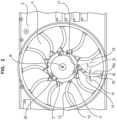
- Fig.1 shows a schematic plan view of a fan frame 2 of a radiator fan module 1 from the prior art with an indicated strut 10 according to an embodiment of the present invention.
- the cooling fan module 1 has a fan frame 2, a fan wheel recess 4 which is formed in the fan frame 2, a motor holder 3 which is mechanically connected to the fan frame 2 via (previously known, straight) struts 100 which are located at the rear as seen in the flow direction, a motor, in particular an electric motor, 5 which is at least partially mounted in the motor holder 3, a fan wheel 6 which is arranged in the fan wheel recess 4 and which is driven by the motor 5 in rotation about a rotation axis R, wherein the fan wheel 6 has a plurality of blade elements 6a.
- the motor mount 3 is connected to the fan frame 2 via straight struts 100, as are well known from the prior art.
- the reference number 10 in the Fig.1 already indicated a strut according to the invention, as will be described in detail below.
- Fig.1 In particular, the geometric difference between previously known struts 100 and the struts 10 according to the invention can be seen.
- Fig.2 shows a schematic plan view of a section of a fan frame 2 according to an embodiment of the present invention.
- the fan frame 2 is made of plastic, in particular in the form of a one-piece plastic injection-molded part.
- the struts 10 extend parabolically from the edge of the fan wheel recess 4 to the motor holder 3 and hold the motor holder in position in the fan wheel recess 4.
- the struts 10 each have a reinforcement 11 which secures the connection between the motor holder 3 and one of the Struts 10 are reinforced.
- the reinforcement 11 is preferably formed in one piece with the strut 10.
- the fan frame 2, the struts 10 and the motor mount 3 are a one-piece plastic injection molded part.
- Fastening interfaces 30 are provided on the motor mount 3, to which a motor 5 can be attached. Furthermore, the angle ⁇ is shown, which indicates the angle at which the strut 10 enters the motor mount 3.
- ⁇ has a value in the range from -30° to +30°.
- an angle ⁇ is shown, which indicates at which angle the strut 10 enters the edge of the fan wheel recess 4.
- the sides of the angle ⁇ are, on the one hand, an extension vector 16 of the strut 10 at the entry point of the strut 10 into the fan frame 2 and, on the other hand, a radial vector 16a through the entry point of the strut 10 into the fan frame 2.
- ⁇ has a value in the range of -90° and +30°.
- a starting point 17 and an end point 18 are occasionally mentioned.
- the starting point 17 is the exit point of the strut 10 from the motor mount 3 and the end point 18 is defined by the entry point of the strut 10 into the fan frame 2.
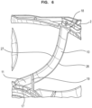
- Fig.3 shows a schematic plan view of a fan frame 2 according to a further embodiment of the present Invention together with two sectional views.
- the cooling fan module 1 shown is a cooling fan module with rear struts 10, ie viewed in the flow direction, which according to the illustration of the Fig.3 out of the blade, the air is first accelerated and compressed by the rotating fan wheel 6 before it hits the struts 10, which represents a particular challenge in the design of such cooling fan modules and in particular the struts 10.
- the fan wheel 6 with the plurality of blade elements 6a is shown for the first time.
- the effect according to the invention can be seen particularly well, how the blade elements 6a - from the perspective of the illustration of the Fig.3 - behind the struts 10 and past them.
- the fan frame 2 has eleven struts 10 according to the invention and the fan wheel 6 has nine blade elements 6a.
- This structural property ensures that each blade element 6a is in a different phase of sweeping over one of the struts 10 at any time during the rotation of the fan wheel. This leads to advantageous, in particular more homogeneous, noise radiation of the entire system.
- Fig.4 shows a schematic perspective view of a single strut 10 according to an embodiment of the present invention.
- This connects the motor holder 3 to the fan frame 2 and holds the motor holder 3 in position in the fan wheel recess 4 of the fan frame 2.
- the struts 10 provide the counter torque which is opposite to the torque generated by the motor with which the fan wheel 6 is driven. For this reason, the struts 10 high forces are conducted, which leads to increased rigidity requirements for it.
- the strut 10 has a parabolic shape.
- a skeleton line 12 of the strut 10 runs from the starting point 17 on the motor mount to the end point 18 on the fan frame 2.
- the apex 13 of the strut is located in the axial direction at least substantially in the middle of the strut 10.
- the strut 10 also has an airfoil profile.
- An area around a leading edge 26 of a profile 20, in particular a cross-sectional profile, is thicker than an area around a trailing edge 27 of the profile 20.
- the airfoil profile of the strut 10 is a semi-symmetrical profile.
- Fig.5 shows a schematic perspective representation of the profile and the course of the strut skeleton line of a single strut 10 according to an embodiment of the present invention.
- the profile 20 of the strut 10 is designed as a semi-symmetrical profile according to this embodiment, wherein the skeleton line 12 of the strut 10 runs parabolically.
- Fig.6 shows a schematic three-dimensional detailed view of a single strut 10 between the motor mount 3 and the fan frame 2 according to an embodiment of the present invention.
- the reinforcement 11 between the strut 10 and the motor mount 3 can be seen.
- the reinforcement 11 has a wall 19 which extends from the strut 10 at an angle. According to one embodiment, this angle corresponds in amount to the angle ⁇ , so that the strut 10 and the wall 19 are arranged mirror-symmetrically to a vertical of the circular motor mount 3.
- the strut 10 is made more stable by the wall 19 and can therefore hold the motor 5 securely in position in the motor mount 3.
- the reinforcement 11 is formed integrally with the strut 10 and the motor mount 3 according to the embodiment shown.
- Fig.7 shows a schematic sectional view of a single strut 10 according to an embodiment of the present invention.
- the profile 20 of the strut 10 according to this embodiment is a semi-symmetrical profile 20.
- a profile curvature of the upper side 21 and a profile curvature of the lower side 22 of the profile 20 run in the same direction.
- the upper side 21 is concavely curved while the lower side 22 has a convex curvature.
- the profile 20 has a profile thickness 23 and a profile depth 25.
- the profile 20 has a nose radius 24, which indicates the radius of the nose of the profile.
- the area of the trailing edge 27 of the profile 20 is narrower than the area of the leading edge 26 of the profile 20.
- the angle of attack ⁇ of the profile according to this embodiment is approximately 45 degrees normal to the blade surface. The air flows in the direction of the arrow 29 around the strut 10.
- Fig.8 shows a schematic sectional view of a single strut 10 according to a further embodiment of the present invention.
- a reinforcement 31 is provided in the strut 10.
- the reinforcement 31 can at least partially comprise metal.
- the reinforcement 31 is made of a steel sheet.
- the reinforcement 31 can also be made of aluminum. This design allows the strut 10 to be made particularly dimensionally stable.
- Fig. 9a shows a diagram with measured values of a state-of-the-art cooling fan module
- Fig. 9b a diagram with measured values of a cooling fan module according to an embodiment of the present invention.
- FIG. 9a and 9b The diagrams shown each show the course of a total level and a fan blade order generated by the system.
- the total level indicates the total noise radiation across all frequencies. In both figures, this is the eleventh fan blade order, which depends on the number of blades, their geometric arrangement and sickle.
- the 10 dB criterion is particularly relevant for evaluating the sound of a fan noise:
- the 10 dB criterion states that those frequency components that are below this 10 dB criterion are not perceived as disturbing. You can imagine it as in an open-plan office, where individual voices are drowned out by the general murmur. Conversely, noise components that violate this 10 dB criterion are perceived as particularly disturbing. If all frequency components are below the 10 dB criterion, the noise radiation is perceived as a pleasant, "rich" hum.
- the pictured Fig. 9a and 9b have been measured at component level in a semi-anechoic chamber with a heat exchanger.
- the design of the struts according to an embodiment of the present invention significantly improves the eleventh fan blade order compared to the state of the art.
- the total level improves by up to 4 dB compared to the state of the art and thus now meets the 10 dB criterion for the first time.
- the struts can, for example, be provided on the pressure side and/or on the vacuum side.
Description
Die vorliegende Erfindung betrifft ein Kühlerlüftermodul, insbesondere ein elektrisch betriebenes Kühlerlüftermodul, insbesondere für Kraftfahrzeuge, mit in Hauptströmungsrichtung gesehen hinten liegenden Streben.The present invention relates to a radiator fan module, in particular an electrically operated radiator fan module, in particular for motor vehicles, with struts located at the rear as seen in the main flow direction.
Das Kühlsystem in einem Verbrennungsmotor, insbesondere eines Kraftfahrzeugs, führt hauptsächlich diejenige Wärme ab, die an die Wände von Brennraum und Zylinder abgegeben wird, weil der Verbrennungsprozess nicht ideal verläuft. Da zu hohe Temperaturen den Motor beschädigen würden (Abreißen des Schmierfilms, Verbrennen der Ventile etc.), muss der Verbrennungsmotor aktiv gekühlt werden.The cooling system in an internal combustion engine, especially in a motor vehicle, mainly removes the heat that is released to the walls of the combustion chamber and cylinder because the combustion process is not ideal. Since temperatures that are too high would damage the engine (tearing off the lubricating film, burning the valves, etc.), the internal combustion engine must be actively cooled.
Moderne Verbrennungsmotoren, insbesondere Viertaktmotoren in Kraftfahrzeugen, werden bis auf wenige Ausnahmen flüssigkeitsgekühlt, wobei in der Regel ein Gemisch aus Wasser, Frostschutzmittel und Korrosionsschutzmittel als Kühlflüssigkeit dient.With a few exceptions, modern internal combustion engines, especially four-stroke engines in motor vehicles, are liquid-cooled, with a mixture of water, antifreeze and corrosion inhibitor usually serving as the coolant.
Die Kühlflüssigkeit wird über Schläuche, Rohre und/oder Kanäle durch den Motor (Zylinderkopf und Motorblock) sowie ggfs. durch thermisch stark beanspruchte Anbauteile des Motors, wie Abgasturbolader, Generator oder Abgasrückführkühler, gepumpt. Hierbei nimmt die Kühlflüssigkeit Wärmeenergie auf und führt sie aus den oben genannten Komponenten ab. Die erwärmte Kühlflüssigkeit fließt weiter zu einem Kühler. Dieser Kühler - früher oftmals aus Messing, heute zumeist aus Aluminium - ist meist an der Front des Kraftahrzeuges angebracht, wo ein Luftstrom Wärmeenergie vom Kühlmittel aufnimmt und dieses damit abkühlt, bevor es wieder zum Motor zurückfließt, wodurch der Kühlmittelkreislauf geschlossen ist.The coolant is pumped through hoses, pipes and/or channels through the engine (cylinder head and engine block) and, if necessary, through parts of the engine that are subject to high thermal stress, such as the exhaust turbocharger, generator or exhaust gas recirculation cooler. The coolant absorbs heat energy and carries it away from the above-mentioned components. The heated coolant flows on to a cooler. This cooler - previously often made of brass, today mostly made of Aluminum - is usually installed at the front of the vehicle, where an air flow absorbs heat energy from the coolant and cools it down before it flows back to the engine, thus closing the coolant circuit.
Um die Luft durch den Kühler zu treiben, wird in (Haupt-) Strömungsrichtung gesehen vor (stromaufwärtig) oder nach (stromabwärtig) dem Kühler ein Kühlerlüftermodul vorgesehen, welches mechanisch über einen Riementrieb oder elektrisch über einen Elektromotor angetrieben sein kann. Die folgenden Ausführungen beziehen sich auf ein elektrisch angetriebenes Kühlerlüftermodul.In order to drive the air through the radiator, a radiator fan module is provided in front of (upstream) or behind (downstream) the radiator in the (main) flow direction, which can be driven mechanically via a belt drive or electrically via an electric motor. The following statements refer to an electrically driven radiator fan module.
Ein Kühlerlüftermodul besteht klassisch aus einer Lüfterzarge, welche eine Lüfterradausnehmung aufweist. In der Lüfterradausnehmung ist ein Motorhalter angeordnet, welcher über Streben mit der Lüfterzarge mechanisch verbunden ist. Die Streben können ausgehend vom Luftvolumenstrom auf der stromabwärtigen oder stromaufwärtigen Seite der Lüfterzarge angeordnet sein. In dem Motorhalter ist ein Motor, insbesondere ein Elektromotor, gehalten. An einer Abtriebswelle des Elektromotors ist ein Lüfterrad angeordnet, welches sich - durch den Elektromotor angetrieben - in der Lüfterradausnehmung dreht.A cooling fan module traditionally consists of a fan frame, which has a fan wheel recess. A motor holder is arranged in the fan wheel recess, which is mechanically connected to the fan frame via struts. The struts can be arranged on the downstream or upstream side of the fan frame, based on the air volume flow. A motor, in particular an electric motor, is held in the motor holder. A fan wheel is arranged on an output shaft of the electric motor, which - driven by the electric motor - rotates in the fan wheel recess.
Bei der Auslegung und Entwicklung von Kühlerlüftermodulen sind neben dem geförderten Luftvolumen pro Zeiteinheit stets auch der zur Verfügung stehende Bauraum, insbesondere seine Anordnung ausgehend vom Luftvolumenstrom stromaufwärtig oder stromabwärtig des Kühlers und/oder seine Abmessungen, und die Geräuschentwicklung relevant.When designing and developing cooling fan modules, in addition to the air volume conveyed per unit of time, the available installation space, in particular its arrangement based on the air volume flow upstream or downstream of the cooler and/or its dimensions, and the noise development are always relevant.
Insbesondere hinsichtlich der Geräuschentwicklung ist es wesentlich, ob die Streben auf der stromaufwärtigen oder stromabwärtigen Seite der Lüfterzarge angeordnet sind, was an den grundverschiedenen aerodynamischen Eigenschaften dieser beiden Varianten liegt: Während die Luft auf der stromaufwärtigen Seite (Saugseite) der Lüfterzarge eher langsam und wenigstens im Wesentlichen laminar strömt, ist sie auf der stromabwärtigen Seite (Druckseite) der Lüfterzarge, d.h. nach dem Hindurchtritt durch die Lüfterradausnehmung, schneller, dichter und verwirbelter als vorher. Aus diesem Grund unterscheiden sich die Anforderungen an vorne- und hintenliegenden Streben - abgesehen von der Hauptanforderung des Haltens des Motorhalters - grundlegend voneinander: Während vorneliegende Streben auch Zuführ- und/oder Luftleitungsfunktionen übernehmen können, sind solche für hintenliegende Streben wenigstens im Wesentlichen irrelevant. Hier kommt es vielmehr darauf an, die Streben aerodynamisch betrachtet möglichst "unsichtbar" zu gestalten, d.h. die Streben so zu gestalten, dass sie die stromabwärtige Luftströmung so wenig wie möglich beeinflussen.With regard to noise development in particular, it is important whether the struts are arranged on the upstream or downstream side of the fan shroud, which is due to the fundamentally different aerodynamic properties of these two variants: While the air flows rather slowly and at least essentially laminarly on the upstream side (suction side) of the fan shroud, it is faster, denser and more turbulent than before on the downstream side (pressure side) of the fan shroud, i.e. after passing through the fan wheel recess. For this reason, the requirements for front and rear struts - apart from the main requirement of holding the motor mount - differ fundamentally from one another: While front struts can also take on supply and/or air conduction functions, these are at least essentially irrelevant for rear struts. Here it is more important to make the struts as "invisible" as possible from an aerodynamic point of view, i.e. to design the struts in such a way that they influence the downstream air flow as little as possible.
Die
Die
Die
Vor diesem Hintergrund liegt der vorliegenden Erfindung die Aufgabe zugrunde, ein verbessertes Kühlerlüftermodul zur Verfügung zu stellen, welches insbesondere hinsichtlich der Geräuschentwicklung vorteilhaft ist.Against this background, the present invention is based on the object of providing an improved cooling fan module which is particularly advantageous with regard to noise development.
Erfindungsgemäß wird diese Aufgabe durch ein Kühlerlüftermodul mit den Merkmalen des Patentanspruchs 1 gelöst.According to the invention, this object is achieved by a cooling fan module having the features of patent claim 1.
Demgemäß weist ein erfindungsgemäßes Kühlerlüftermodul eine Lüfterzarge, eine Lüfterradausnehmung, welche in der Lüfterzarge ausgebildet ist, einen Motorhalter, welcher über in Strömungsrichtung gesehen hintenliegenden Streben mit der Lüfterzarge mechanisch verbunden ist, einen Motor, insbesondere Elektromotor, welcher zumindest teilweise in dem Motorhalter gelagert ist, und ein Lüfterrad, welches in der Lüfterradausnehmung angeordnet ist und welches von dem Motor rotatorisch um eine Rotationachse angetrieben wird, wobei das Lüfterrad eine Mehrzahl von Flügelelementen aufweist, auf, wobei wenigstens alle Elemente einer Gruppe, welche wenigstens eine der Streben und wenigstens eines der Flügelelemente aufweist, vorwärtsgesichelt oder rückwärtsgesichelt sind.Accordingly, a cooling fan module according to the invention has a fan frame, a fan wheel recess which is formed in the fan frame, a motor holder which is mechanically connected to the fan frame via struts which are located at the rear as seen in the flow direction, a motor, in particular an electric motor, which is at least partially mounted in the motor holder, and a fan wheel which is arranged in the fan wheel recess and which is driven by the motor in rotation about a rotation axis, wherein the fan wheel has a plurality of blade elements, wherein at least all elements of a group which has at least one of the struts and at least one of the blade elements are forward-sickled or backward-sickled.
Ein "Kühlerlüftermodul" im Sinne der vorliegenden Erfindung ist insbesondere eine Baugruppe, welche in Strömungsrichtung gesehen vor oder nach einem Kühler eines Fahrzeugs angeordnet ist und welche dafür vorgesehen, insbesondere eingerichtet, ist, einen Luftvolumenstrom zu erzeugen, welcher sich durch den Kühler hindurch und/oder um den Kühler herum erstreckt, wobei der Luftvolumenstrom thermische Energie von dem Kühler aufnimmt.A "radiator fan module" in the sense of the present invention is in particular an assembly which, as seen in the flow direction, is arranged before or after a radiator of a vehicle and which is intended, in particular designed, to generate an air volume flow which extends through the radiator and/or around the radiator, wherein the air volume flow absorbs thermal energy from the radiator.
Eine "Lüfterzarge" im Sinne der vorliegenden Erfindung ist insbesondere ein Rahmen, in welchem das Lüfterrad gehalten ist, und selbst wiederum bevorzugt an oder in der Nähe des Kühlers angeordnet, insbesondere befestigt, ist. Eine Lüfterzarge im Sinne der vorliegenden Erfindung weist bevorzugt ein Kunststoffmaterial, insbesondere einen Kunststoff-Compound, auf, insbesondere ist die Lüfterzarge aus diesem gebildet. Zusätzlich und/oder alternativ weist die Lüfterzarge ein Metallmaterial, zum Beispiel Eisen, Stahl, Aluminium, Magnesium oder dergleichen, auf, insbesondere ist zumindest teilweise, insbesondere wenigstens im Wesentlichen, insbesondere vollständig, aus diesem gebildet. Nach einer Ausführung kann eine Lüfterzarge auch mehr als eine Lüfterradausnehmung, einen Motorhalter, einen Motor und ein Lüfterrad aufweisen, insbesondere ist die vorliegende Erfindung zum Einsatz in Kühlerlüftermodulen mit zwei oder mehr, insbesondere zwei, Lüfterrädern geeignet. Nach einer Ausführung weist die Lüfterzarge zusätzlich wenigstens eine verschließbare Öffnung, insbesondere wenigstens eine Klappe, insbesondere eine Mehrzahl derselben, auf. Dies ist insbesondere vorteilhaft, da auf diese Weise weitere Luftführungseigenschaften realisiert werden können.A "fan frame" in the sense of the present invention is in particular a frame in which the fan wheel is held and is itself preferably arranged, in particular fastened, on or near the cooler. A fan frame in the sense of the present invention preferably comprises a plastic material, in particular a plastic compound, in particular the fan frame is formed from this. Additionally and/or alternatively, the fan frame comprises a metal material, for example iron, steel, aluminum, magnesium or the like, in particular is at least partially, in particular at least substantially, in particular completely, formed from this. According to one embodiment, a fan frame can also have more than one fan wheel recess, a motor holder, a motor and a fan wheel; in particular, the present invention is suitable for use in radiator fan modules with two or more, in particular two, fan wheels. According to one embodiment, the fan frame additionally has at least one closable opening, in particular at least one flap, in particular a plurality of the same. This is particularly advantageous since further air guidance properties can be realized in this way.
Eine "Lüfterradausnehmung" im Sinne der vorliegenden Erfindung ist insbesondere eine Materialaussparung innerhalb der Lüfterzarge. In der Lüfterradausnehmung erstrecken sich nach einer Ausführung der vorliegenden Erfindung Streben, welche einen ebenfalls in der Lüfterradausnehmung angeordneten Motorhalter mit der Lüfterzarge mechanisch, insbesondere und elektrisch und/oder elektronisch, verbinden. Gemäß einer Ausführung der vorliegenden Erfindung wird die Lüfterradausnehmung durch einen Zargenring begrenzt.A "fan wheel recess" in the sense of the present invention is in particular a material recess within the fan frame. According to one embodiment of the present invention, struts extend in the fan wheel recess, which mechanically, in particular electrically and/or electronically, connect a motor holder, which is also arranged in the fan wheel recess, to the fan frame. According to one embodiment of the present invention, the fan wheel recess is delimited by a frame ring.
Ein "Motorhalter" im Sinne der vorliegenden Erfindung ist insbesondere eine Einrichtung zur mechanischen Befestigung des Motors an der Lüfterzarge, insbesondere zur Bereitstellung des dem Lüfterrad entgegenwirkenden Drehmoments. Nach einer Ausführung ist der Motorhalter eine wenigstens im Wesentlichen ringförmige Struktur, in welcher der Motor gehalten ist. Dies ist insbesondere vorteilhaft, da auf diese Weise eine vorteilhafte Kühlluftströmung durch den Motor nicht beeinträchtigt wird.A "motor holder" in the sense of the present invention is in particular a device for mechanically fastening the motor to the fan frame, in particular for providing the torque that counteracts the fan wheel. According to one embodiment, the motor holder is an at least substantially ring-shaped structure in which the motor is held. This is particularly advantageous because in this way a beneficial cooling air flow through the motor is not impaired.
"Strömungsrichtung" im Sinne der vorliegenden Erfindung bezeichnet insbesondere die sogenannte Hauptströmungsrichtung, also diejenige Strömung, welche parallel zur Rotationsachse des Lüfterrades durch die Lüfterradausnehmung der Lüfterzarge hindurchtritt, und zur Kühlung des Kühlers genutzt wird."Flow direction" in the sense of the present invention refers in particular to the so-called main flow direction, i.e. the flow which passes parallel to the axis of rotation of the fan wheel through the fan wheel recess of the fan frame and is used to cool the cooler.
"Streben" im Sinne der vorliegenden Erfindung sind insbesondere balken- oder sichelförmige Strukturen, welche eine mechanische Verbindung zwischen dem Motorhalter und der Lüfterzarge bereitstellen. Gemäß einer Ausführung der vorliegenden Erfindung können die Streben einen tropfenförmigen Querschnitt aufweisen, um vorteilhafte aerodynamische und/oder akustische Effekte zu erzielen."Struts" in the sense of the present invention are in particular bar- or sickle-shaped structures which provide a mechanical connection between the motor mount and the fan frame. According to one embodiment of the present invention, the struts can have a teardrop-shaped cross-section in order to achieve advantageous aerodynamic and/or acoustic effects.
Ein "Motor" im Sinne der vorliegenden Erfindung ist insbesondere eine Maschine, die mechanische Arbeit verrichtet, indem sie eine Energieform, zum Beispiel thermische/chemische oder elektrische Energie, in Bewegungsenergie, insbesondere ein Drehmoment, umwandelt. Dies ist insbesondere vorteilhaft, da auf diese Weise die Lüfterzarge bis auf die Zufuhr von Energie wenigstens im Wesentlichen autark betrieben werden kann, das heißt ohne von extern mit Bewegungsenergie versorgt zu werden, wie zum Beispiel über einen Keil- oder Zahnriemen.A "motor" in the sense of the present invention is in particular a machine that performs mechanical work by converting a form of energy, for example thermal/chemical or electrical energy, into kinetic energy, in particular a torque. This is particularly advantageous because in this way the fan frame can be operated at least essentially autonomously apart from the supply of energy, i.e. without being supplied with kinetic energy from outside, for example via a V-belt or toothed belt.
Ein "Elektromotor" im Sinne der vorliegenden Erfindung ist ein elektromechanischer Wandler (elektrische Maschine), der elektrische Leistung in mechanische Leistung, insbesondere in ein Drehmoment, umwandelt. Der Begriff Elektromotor im Sinne der vorliegenden Erfindung umfasst, ist aber nicht beschränkt auf Gleichstrommotoren, Wechselstrommotoren und Drehstrommotoren bzw. bürstenbehaftete und bürstenlose Elektromotoren bzw. Innenläufer- und Außenläufermotoren. Dies ist insbesondere vorteilhaft, da elektrische Energie eine im Vergleich zu mechanischer oder chemischer Energie leicht zu übertragende Energieform darstellt, mit welcher das erforderliche Drehmoment zum Antrieb des Lüfterrades bereitgestellt wird.An "electric motor" in the sense of the present invention is an electromechanical converter (electric machine) that converts electrical power into mechanical power, in particular into torque. The term electric motor in the sense of the present invention includes, but is not limited to, direct current motors, alternating current motors and three-phase motors or brushed and brushless electric motors or internal rotor and external rotor motors. This is particularly advantageous because electrical energy is easy to transmit compared to mechanical or chemical energy. Form of energy with which the required torque is provided to drive the fan wheel.
Ein "Lüfterrad" im Sinne der vorliegenden Erfindung ist insbesondere eine rotationssymmetrische Komponente, welche eine Nabe, insbesondere einen Nabentopf, welcher das Lüfterrad mit einem Motor, insbesondere über eine aus diesem herausragende Welle, verbindet in einer Weise, dass das Drehmoment, welches von dem Motor erzeugt wird, wenigstens im Wesentlichen vollständig auf das Lüfterrad übertragen wird.A "fan wheel" in the sense of the present invention is in particular a rotationally symmetrical component which has a hub, in particular a hub pot, which connects the fan wheel to a motor, in particular via a shaft protruding from it, in such a way that the torque generated by the motor is at least substantially completely transmitted to the fan wheel.
Ein "Flügelelement" im Sinne der vorliegenden Erfindung ist ein gegenüber einer Ebene, auf welcher die Rotationsachse senkrecht steht, geneigter wenigstens im Wesentlichen flacher Körper, welcher an dem Nabentopf angeordnet ist und welcher dafür vorgesehen, insbesondere eingerichtet, ist, einen Luftvolumenstrom zu erzeugen, sobald das Lüfterrad in eine rotatorische Bewegung versetzt wird. Die Flügelelemente sind dabei bevorzugt gegenüber der Rotationsachse geneigt in einem Winkelbereich von -90° bis +90°, insbesondere von -75° bis +75°, insbesondere von -60° bis +60°, insbesondere von -45° bis +45°, insbesondere von -30° bis +30° und besonders bevorzugt von -15° bis +15°. Unter Flügelelementen im Sinne der vorliegenden Erfindung werden insbesondere auch Flügel, Schaufelblätter oder Rotorblätter verstanden.A "vane element" in the sense of the present invention is an at least substantially flat body which is inclined relative to a plane on which the axis of rotation is perpendicular, which is arranged on the hub pot and which is intended, in particular designed, to generate an air volume flow as soon as the fan wheel is set in a rotary motion. The vane elements are preferably inclined relative to the axis of rotation in an angular range of -90° to +90°, in particular from -75° to +75°, in particular from -60° to +60°, in particular from -45° to +45°, in particular from -30° to +30° and particularly preferably from -15° to +15°. Vane elements in the sense of the present invention are also understood to mean in particular vanes, blades or rotor blades.
"Vorwärtsgesichelt" im Sinne der vorliegenden Erfindung bedeutet insbesondere, dass die Spitze des Flügelelementes in Drehrichtung betrachtet der Mitte des Flügelelementes vorauseilt."Forward sickle" in the sense of the present invention means in particular that the tip of the wing element, viewed in the direction of rotation, leads the center of the wing element.
"Rückwärtsgesichelt" im Sinne der vorliegenden Erfindung bedeutet insbesondere, dass die Spitze des Flügelelementes in Drehrichtung betrachtet der Mitte des Flügelelementes nacheilt."Backward sickle" in the sense of the present invention means in particular that the tip of the wing element lags behind the center of the wing element when viewed in the direction of rotation.
Erfindungsgemäß folgt die Geometrie der wenigstens einen Strebe wenigstens im Wesentlichen der Geometrie des wenigstens einen Flügelelementes bezüglich der Ausdehnung in einer Ebene senkrecht zur Rotationsachse. Erfindungsgemäß folgt die Geometrie der Strebenskelettlinie der wenigstens einen Strebe wenigstens im Wesentlichen der Geometrie der Flügelelementskelettlinie des wenigstens einen Flügelelementes bezüglich der Ausdehnung in einer Ebene senkrecht zur Rotationsachse Dies ist insbesondere vorteilhaft, da auf diese Weise wenigstens einer der negativen Effekte der, insbesondere hintenliegenden, Streben vermindert werden kann, insbesondere bezüglich der Akustik. Dazu muss man wissen, dass Streben bei der Entwicklung von Lüfterzargen stets störend sind. Der Volumenstrom, welcher durch das Lüfterrad erzeugt wird, besitzt insbesondere in Strömungsrichtung gesehen kurz hinter dem Lüfterrad eine erhöhte Dichte und die einzelnen Luftmoleküle bewegen sich mit sehr hoher Geschwindigkeit und einem durch das Lüfterrad erzeugten Drall vorwärts. In dieser Ausgangssituation treffen die Luftmoleküle auf die "im Weg stehenden" Streben, wodurch eine Abbremsung und Richtungsänderung der Luftmoleküle erfolgt. Hierbei entstehen unerwünschte Geräusche, insbesondere dann wenn der Flügel, insbesondere dessen Vorderkante, über die Strebe hinwegstreicht. Dies erzeugt unerwünschte Geräusche, insbesondere das sogenannte "Blocken", welches weiter unten nochmals eingehend beschrieben wird. Indem die Geometrie der Strebe hinsichtlich der radialen Erstreckung wenigstens im Wesentlichen der Geometrie des Flügelelementes folgt, kann erzielt werden, dass die Vorderkante des Flügelelements nicht auf gesamter Länge gleichzeitig auf die Strebe trifft, sondern dass es hier lediglich stets einen Überlagerungspunkt gibt, welcher in radialer Richtung wandert. Man denke hierbei beispielsweise an eine handelsübliche Papierschere, bei welcher der Schnittpunkt der beiden Schneiden entlang der Erstreckungsrichtung wandert, sobald die Schere geschlossen wird.According to the invention, the geometry of the at least one strut at least essentially follows the geometry of the at least one wing element with respect to the extension in a plane perpendicular to the axis of rotation. According to the invention, the geometry of the strut skeleton line of the at least one strut at least essentially follows the geometry of the wing element skeleton line of the at least one wing element with respect to the extension in a plane perpendicular to the axis of rotation. This is particularly advantageous because in this way at least one of the negative effects of the struts, in particular those at the rear, can be reduced, in particular with respect to acoustics. It is important to know that struts are always disruptive when developing fan frames. The volume flow generated by the fan wheel has an increased density, particularly in the direction of flow, just behind the fan wheel, and the individual air molecules move forward at very high speed and with a swirl generated by the fan wheel. In this initial situation, the air molecules hit the struts "standing in the way", which causes the air molecules to slow down and change direction. This creates undesirable noise, particularly when the blade, in particular its leading edge, passes over the strut. This creates unwanted noise, particularly the so-called "blocking", which is described in more detail below. By ensuring that the geometry of the strut follows the geometry of the wing element at least essentially in terms of radial extension, it is possible to ensure that the leading edge of the wing element does not hit the strut at the same time over its entire length, but that there is always only one overlap point that moves in the radial direction. For example, consider a commercially available Paper scissors in which the intersection point of the two cutting edges moves along the direction of extension as soon as the scissors are closed.
Nach einer Ausführung der vorliegenden Erfindung umfasst die Gruppe eine Mehrzahl, insbesondere alle, der Streben und/oder eine Mehrzahl, insbesondere alle, der Flügelelemente.According to one embodiment of the present invention, the group comprises a plurality, in particular all, of the struts and/or a plurality, in particular all, of the wing elements.
Dies ist insbesondere vorteilhaft, da auf diese Weise der oben beschriebene Effekt verstärkt wird. Je mehr Streben bzw. Flügelelemente erfindungsgemäß aufeinander abgestimmt sind, desto vorteilhafter sind die Eigenschaften des Kühlerlüftermoduls hinsichtlich der Geräuschentwicklung.This is particularly advantageous because the effect described above is enhanced in this way. The more struts or wing elements are coordinated with one another according to the invention, the more advantageous the properties of the cooling fan module are in terms of noise development.
Nach einer weiteren Ausführung der vorliegenden Erfindung stehen eine Flügelelementskelettlinie der Flügelelemente der Gruppe und eine Strebenskelettlinie der Streben der Gruppe in einem Profilschnitt miteinander in Beziehung über: 

- X-Koordinate
- beschreibt die X-Koordinate des Schnittpunktes der Strebenskelettlinie mit einer Schnittebene in einem x-y-Koordinatensystem in der Schnittebene
- Y-Koordinate
- beschreibt die Y-Koordinate des Schnittpunktes der Strebenskelettlinie mit einer Schnittebene in einem x-y-Koordinatensystem in der Schnittebene
- n
- beschreibt einen aktuell betrachteten Profilschnitt
- nmax
- beschreibt, in wie viele äquidistante Profilschnitte die Strebe und das Flügelelement über ihre radiale Erstreckung hinweg unterteilt werden; wobei
- αs(n)
- beschreibt einen Sichelungswinkel am Profilschnitt n des Flügelelements, d.h. einen Winkel zwischen einem zur Rotationsachse parallel verschobenen ersten Schenkel und einem zweiten Schenkel, welcher durch die Punkte von Vorderund Hinterkante der Strebe in der Schnittebene definiert ist;
- DH
- beschreibt den Außendurchmesser des Motorhalters (3) ;
- LP
- beschreibt die Profillänge der Strebe (10), d.h. den Abstand zwischen Vorder- und Hinterkante der Strebe in der Schnittebene;
- βs(n)
- beschreibt einen Korrekturfaktor der Sichelung, wobei

βR(n) beschreibt einen Korrekturfaktor der Profilrotation, wobei
- X-coordinate
- describes the X-coordinate of the intersection point of the strut skeleton line with a cutting plane in an xy-coordinate system in the cutting plane
- Y-coordinate
- describes the Y-coordinate of the intersection point of the strut skeleton line with a cutting plane in an xy-coordinate system in the cutting plane
- n
- describes a currently viewed profile section
- nmax
- describes how many equidistant profile sections the strut and the wing element are divided into over their radial extension; where
- αs(n)
- describes a sickle angle at the profile section n of the wing element, ie an angle between a first leg displaced parallel to the axis of rotation and a second leg, which is defined by the points of the leading and trailing edges of the strut in the cutting plane;
- DH
- describes the outer diameter of the motor mount (3);
- LP
- describes the profile length of the strut (10), ie the distance between the front and rear edges of the strut in the cutting plane;
- βs(n)
- describes a correction factor of the sickle, where
β R (n) describes a correction factor of the profile rotation, where
Eine "Strebenskelettlinie" im Sinne der vorliegenden Erfindung, auch Profilmittellinie, Wölbungslinie oder Krümmungslinie genannt, bezeichnet die Verbindungslinie der in ein Profil einbeschriebenen Kreismittelpunkte, wobei die Skelettlinie vom Nasenkreismittelpunkt bis zur Profilnase gerade verläuft. Eine weitere alternative Definition, welche im Sinne der Erfindung explizit mit umfasst ist, definiert die Strebenskelettlinie dahingehend, dass diese aus den Mittelpunkten zwischen der Ober- und Unterseite senkrecht zur X-Koordinate oder Profilsehne besteht. Der Verlauf der Skelettlinie bestimmt die Strömungseigenschaften wesentlich mit. Wichtige geometrische Kennzahlen sind die Wölbungshöhe und die Wölbungsrücklage, wobei Strebenprofile mit gerader oder S-förmiger Skelettlinie einen Druckpunkt haben, der sich nur wenig mit dem Anstellwinkel ändert.A "strut skeleton line" in the sense of the present invention, also called profile center line, camber line or curvature line, refers to the connecting line of the circle centers inscribed in a profile, whereby the skeleton line runs straight from the nose circle center to the profile nose. Another alternative definition, which in the sense the invention is explicitly included, defines the strut skeleton line in such a way that it consists of the midpoints between the top and bottom perpendicular to the X coordinate or profile chord. The course of the skeleton line determines the flow properties to a large extent. Important geometric parameters are the camber height and the camber offset, whereby strut profiles with a straight or S-shaped skeleton line have a pressure point that changes only slightly with the angle of attack.
Unter einer "Flügelelementskelettlinie" im Sinne der obenliegenden Erfindung, auch Profilmittellinie, Wölbungslinie oder Krümmungslinie genannt, bezeichnet die Verbindungslinie der in ein Profil einbeschriebenen Kreismittelpunkte, wobei die Skelettlinie vom Nasenkreismittelpunkt bis zur Profilnase gerade verläuft. Eine weitere alternative Definition, welche im Sinne der Erfindung explizit mit umfasst ist, definiert die Flügelelementskelettlinie dahingehend, dass diese aus den Mittelpunkten zwischen der Ober- und Unterseite senkrecht zur X-Koordinate oder Profilsehne besteht. Der Verlauf der Skelettlinie bestimmt die Strömungseigenschaften wesentlich mit. Wichtige geometrische Kennzahlen sind die Wölbungshöhe und die Wölbungsrücklage, wobei Flügelelementprofile mit gerader oder S-förmiger Skelettlinie einen Druckpunkt haben, der sich nur wenig mit dem Anstellwinkel ändert.A "wing element skeleton line" in the sense of the above invention, also called profile center line, camber line or curvature line, refers to the connecting line of the circle centers inscribed in a profile, with the skeleton line running straight from the nose circle center to the profile nose. Another alternative definition, which is explicitly included in the sense of the invention, defines the wing element skeleton line as consisting of the centers between the upper and lower sides perpendicular to the X coordinate or profile chord. The course of the skeleton line significantly determines the flow properties. Important geometric parameters are the camber height and the camber offset, with wing element profiles with a straight or S-shaped skeleton line having a pressure point that changes only slightly with the angle of attack.
Die o.g. funktionalen Zusammenhänge sind das Ergebnis umfangreicher wissenschaftlicher Untersuchungen und Versuche, welche erstmals eine Beziehung zwischen Strebenskelettlinie und Flügelelementskelettlinie beschreiben. Hierzu wird die radiale Erstreckungsrichtung der Flügelelemente bzw. Streben in eine Anzahl nmax äquidistante Profilschnitte unterteilt, wobei die hier beschriebenen Zusammenhänge für wenigstens einen, insbesondere eine Mehrzahl, insbesondere eine überwiegende Mehrzahl, nmax Profilschnitte erfüllt sein müssen.The above functional relationships are the result of extensive scientific investigations and tests, which describe for the first time a relationship between the strut skeleton line and the wing element skeleton line. For this purpose, the radial extension direction of the wing elements or struts is divided into a number n max equidistant profile sections, whereby the relationships described here apply to at least one, in particular a majority, in particular a predominant majority, n max profile sections must be fulfilled.
Über die Flügelelementskelettlinie welche die Sichelung des Flügelelements erzeugt, fließt die Geometrie des Flügelelements unmittelbar in die Auslegung der Strebe mit ein.The geometry of the wing element is directly incorporated into the design of the strut via the wing element skeleton line, which creates the sickle of the wing element.
Die Formel beinhaltet Parameter der Flügelelementskelettlinie im Form des Sichelungswinkels αs(n) am Profilschnitt n des Flügelelements. Somit besteht erstmals ein funktionaler Zusammenhang zwischen der Geometrie des Flügelelements und der Strebe, was zu einem besonders vorteilhaften Klangbild des Gesamtsystems führt. Dies ist insbesondere für elektrisch betriebene Fahrzeuge relevant, die eine deutlich geringere Geräuschabstrahlung aufweisen, weshalb ein vorbekanntes Kühlerlüftermodul zu einer unangenehmen Geräuschwahrnehmung führen würde, da die überdeckenden Geräusche des klassischen Hauptantriebssystems, d.h. des Verbrennungsmotors, wegfallen.The formula contains parameters of the wing element skeleton line in the form of the sickle angle α s (n) at the profile section n of the wing element. This means that for the first time there is a functional connection between the geometry of the wing element and the strut, which leads to a particularly advantageous sound image of the overall system. This is particularly relevant for electrically powered vehicles, which emit significantly less noise, which is why a previously known radiator fan module would lead to an unpleasant noise perception, since the masking noise of the classic main drive system, i.e. the combustion engine, is eliminated.
Nach einer weiteren Ausführung der vorliegenden Erfindung gelten die definierten funktionalen Zusammenhänge für X- und Y-Koordinaten für alle Schnitte n ∈ [0;n max].According to a further embodiment of the present invention, the defined functional relationships for X and Y coordinates apply to all sections n ∈ [0; n max ].
Dies ist insbesondere vorteilhaft, da auf diese Weise die definierten funktionalen Zusammenhänge für X- und Y-Koordinaten, welche sich in umfangreichen Versuchsreihen als vorteilhaft herausgestellt haben, für die gesamte radiale Erstreckung von Flügelelement und Strebe gelten. Somit kann der vorteilhafte Effekt, der Geräuschreduzierung weiter verbessert werden, da das Überstreichen der Streben durch das Flügelelement "sanft" erfolgen kann, d.h. mit einer verminderten Beeinflussung des Strömungsvektors des Hauptvolumenstroms.This is particularly advantageous because the defined functional relationships for X and Y coordinates, which have proven to be advantageous in extensive series of tests, apply to the entire radial extension of the wing element and strut. This means that the advantageous effect of noise reduction can be further improved because the wing element can sweep over the struts "gently", i.e. with a reduced influence on the flow vector of the main volume flow.
Nach einer weiteren Ausführung der vorliegenden Erfindung weisen die Streben ein halbsymmetrisches Profil auf.According to a further embodiment of the present invention, the struts have a semi-symmetrical profile.
Ein "Profil" im Sinne der vorliegenden Erfindung ist insbesondere die Form des Querschnitts der Strebe, wobei die Schnittebene senkrecht auf einem Radialvektor des Kühlerlüftermoduls steht. Dieser Radialvektor ist zum einen definiert durch die Ausrichtung der Rotationsachse, auf welcher dieser Vektor senkrecht steht, sowie dem Punkt der Strebenskelettlinie in der zu betrachtenden Schnittebene.A "profile" in the sense of the present invention is in particular the shape of the cross section of the strut, with the cutting plane being perpendicular to a radial vector of the cooling fan module. This radial vector is defined on the one hand by the orientation of the axis of rotation to which this vector is perpendicular, and the point of the strut skeleton line in the cutting plane to be considered.
Als "halbsymmetrisches Profil" im Sinne der vorliegenden Erfindung, auch bikonvexes Profil genannt, ist ein Profil geringer Wölbung, insbesondere im Bereich von 1-3%, zu verstehen, welches zwar eine Wölbung aufweist, aber keine konkaven Konturen.A "semi-symmetrical profile" in the sense of the present invention, also called a biconvex profile, is to be understood as a profile with a low curvature, in particular in the range of 1-3%, which has a curvature but no concave contours.
Dies ist insbesondere vorteilhaft, da auf diese Weise die oben beschriebenen Vorteile des erfindungsgemäßen Kühlerlüftermoduls weiter verbessert werden können, indem nicht nur die Lage der Strebe im Verhältnis zum Flügelelement optimiert wird, sondern auch die Ausgestaltung der Strebe, sodass sich diese möglichst vorteilhaft in den Hauptvolumenstrom einfügt, um somit ein Ab- und/oder Umlenken des Luftvolumenstroms so gut es eben geht zu vermeiden.This is particularly advantageous because in this way the above-described advantages of the cooling fan module according to the invention can be further improved by not only optimizing the position of the strut in relation to the wing element, but also the design of the strut so that it fits into the main volume flow as advantageously as possible in order to avoid diversion and/or redirection of the air volume flow as much as possible.
Nach einer weiteren Ausführung der vorliegenden Erfindung sind die Streben zur Rotationsachse mit einem Anstellwinkel α im Bereich zwischen 5 Grad und 45 Grad, vorzugsweise zwischen 10 Grad und 25 Grad, angeordnet.According to a further embodiment of the present invention, the struts are arranged with an angle of attack α in the range between 5 degrees and 45 degrees, preferably between 10 degrees and 25 degrees, relative to the axis of rotation.
Der "Anstellwinkel" im Sinne der vorliegenden Erfindung auch "Anströmwinkel" benannt, ist der Winkel zwischen der Richtung des anströmenden Fluids und der Seele des Profils, also der gedachten geradlinigen Verbindung zwischen der Profilnase und der Profilhinterkante.The "angle of attack" in the sense of the present invention, also called "angle of attack", is the angle between the direction of the incoming fluid and the core of the profile, i.e. the imaginary straight line connection between the profile nose and the profile trailing edge.
Dies ist insbesondere vorteilhaft, da auf diese Weise ein weiterer Parameter angegeben ist, mit welchem die Strebe so ausgelegt werden kann, dass die Ab- und/oder Umlenkung des Hauptvolumenstroms weiter vermindert wird.This is particularly advantageous because it provides a further parameter with which the strut can be designed in such a way that the diversion and/or deflection of the main volume flow is further reduced.
Nach einer weiteren Ausführung der vorliegenden Erfindung treten die Streben aus dem Motorhalter mit einem Winkel β aus, welcher einen Wert im Bereich von -30° bis +30°, insbesondere im Bereich von -20° bis +20°, insbesondere im Bereich von -10° bis +10°, aufweist.According to a further embodiment of the present invention, the struts emerge from the engine mount at an angle β which has a value in the range of -30° to +30°, in particular in the range of -20° to +20°, in particular in the range of -10° to +10°.
Dies ist insbesondere vorteilhaft, da umfangreiche Versuchs- und Vergleichstudien ergeben haben, dass ein zu steiles Austreten der Strebe aus dem Motorhalter dazu führt, dass die Länge erheblich vergrößert wird, wodurch ein positiver Effekt, welcher durch ein "sanftes" Übereinandergleiten der Kanten durch die Länge der Strebe wieder aufgehoben oder ggf. ins Gegenteil verkehrt wird.This is particularly advantageous because extensive test and comparison studies have shown that if the strut emerges from the engine mount too steeply, the length is increased considerably, thereby canceling out or possibly reversing a positive effect caused by a "gentle" sliding of the edges over each other through the length of the strut.
Nach einer weiteren Ausführung der vorliegenden Erfindung treten die Streben in die Lüfterzarge ein mit einem vorgegebenen Winkel ϕ, welcher einen Wert im Bereich von -90° und +30°, insbesondere im Bereich von -75° und +15°, insbesondere im Bereich von -60° bis 0°, aufweist. Dies ist insbesondere vorteilhaft, da auf diese Weise die Streben auch als Eingriffsschutz angeordnet und bei der Auslegung des Systems auf den vorhandenen Bauraum angepasst werden können.According to a further embodiment of the present invention, the struts enter the fan frame at a predetermined angle ϕ, which has a value in the range of -90° and +30°, in particular in the range of -75° and +15°, in particular in the range of -60° to 0°. This is particularly advantageous because in this way the struts can also be arranged as protection against interference and can be adapted to the available installation space when designing the system.
Nach einer weiteren Ausführung der vorliegenden Erfindung ist eine Verstärkung vorgesehen, die zwischen dem Motorhalter und einer der Streben, insbesondere zwischen dem Motorhalter und einer Mehrzahl der Streben, insbesondere zwischen dem Motorhalter und jeder Strebe, ausgebildet ist.According to a further embodiment of the present invention, a reinforcement is provided which is formed between the engine mount and one of the struts, in particular between the engine mount and a plurality of the struts, in particular between the engine mount and each strut.
Dies ist insbesondere vorteilhaft, da auf diese Weise die Steifigkeit des Kühlerlüftermoduls insgesamt und besonders der Streben verbessert werden kann. Diese Versteifung gerade zwischen Motorhalter und Strebe ist besonders vorteilhaft, da durch das Gegenmoment zum Antriebsdrehmoment des Motors gerade am Übergang zwischen Motorhalter und Strebe hohe Scherkräfte auftreten. Des Weiteren gleichen die o.g. Vorteile einer Materialanhäufung im Strebenbereich unmittelbar am Motorhalter die damit einhergehenden aerodynamischen Nachteile zumindest teilweise aus, da die Rotations- und Volumenstromgeschwindigkeit in diesem Bereich im Vergleich zum Außenradius der Flügelelemente vergleichsweise niedrig ist.This is particularly advantageous because it improves the rigidity of the cooling fan module as a whole and especially of the struts. This stiffening between the engine mount and the strut is particularly advantageous because the counter torque to the drive torque of the engine causes high shear forces to occur at the transition between the engine mount and the strut. Furthermore, the above-mentioned advantages of a material accumulation in the strut area directly on the engine mount at least partially compensate for the associated aerodynamic disadvantages because the rotation and volume flow speed in this area is comparatively low compared to the outer radius of the blade elements.
Die Verstärkung ist insbesondere in Form einer Materialansammlung ausgebildet, welche den Radius am Übergang von der Strebe zum Motorhalter vergrößert, um somit insbesondere eine verbesserte Krafteinleitung zu ermöglichen.The reinforcement is designed in particular in the form of a material accumulation which increases the radius at the transition from the strut to the engine mount in order to enable, in particular, improved force introduction.
Dies ist nach einer Ausführung insbesondere vorteilhaft, da die Verstärkung die Festigkeit einer Strebe steigert, sodass die Strebe sehr formstabil ist. Die Verstärkung ist vorzugsweise einstückig mit der Strebe und/oder dem Motorhalter ausgebildet.This is particularly advantageous according to one embodiment, since the reinforcement increases the strength of a strut, so that the strut is very dimensionally stable. The reinforcement is preferably formed in one piece with the strut and/or the motor mount.
Nach einer weiteren Ausführung der vorliegenden Erfindung sind die Lüfterzarge, der Motorhalter und die Streben als einstückiges Kunststoffspritzgussteil ausgebildet.According to a further embodiment of the present invention, the fan shroud, the motor mount and the struts are formed as a one-piece plastic injection-molded part.
Dies ist insbesondere vorteilhaft, da auf diese Weise ein kosteneffizientes near-to-end-shape-Urformverfahren verwendet werden kann, um die Lüfterzarge zusammen mit Motorhalter und Streben bereitzustellen.This is particularly advantageous because it allows a cost-effective near-to-end-shape primary forming process to be used to provide the fan shroud together with the motor mount and struts.
Nach einer weiteren Ausführung der vorliegenden Erfindung weisen die Streben eine Armierung auf.According to a further embodiment of the present invention, the struts have a reinforcement.
Nach einer weiteren Ausführung weist die Armierung zumindest teilweise Metall auf. Beispielsweise ist die Armierung in Form eines Stahlblechs ausgebildet. Dies ist nach einer Ausführung insbesondere vorteilhaft, da auf diese Weise die Formstabilität und die Festigkeit der Streben gesteigert werden kann.According to a further embodiment, the reinforcement comprises at least some metal. For example, the reinforcement is in the form of a steel sheet. This is particularly advantageous according to one embodiment, since the dimensional stability and strength of the struts can be increased in this way.
Das Kühlerlüftermodul weist genau zwei Streben mehr auf als Flügelelemente, insbesondere weist das Kühlerlüftermodul elf Streben und neun Flügelelemente auf. Diese Ausgestaltung ist insbesondere vorteilhaft, da auf diese Weise sich jedes Flügelelement in einer anderen Phase des Überstreichens der Strebe befindet, was mit Blick auf das Gesamtsystem zu einer homogeneren Geräuschabstrahlung führt.The cooling fan module has exactly two struts more than blade elements, in particular the cooling fan module has eleven struts and nine blade elements. This design is particularly advantageous because in this way each blade element is in a different phase of sweeping over the strut, which leads to a more homogeneous noise emission with regard to the overall system.
Die obigen Ausgestaltungen und Weiterbildungen lassen sich, sofern sich aus der Beschreibung für den Fachmann nicht in eindeutiger Weise ein Anderes ergibt, beliebig miteinander kombinieren. Weitere mögliche Ausgestaltungen, Weiterbildungen und Implementierungen der Erfindung umfassen auch nicht explizit genannte Kombinationen von zuvor oder im Folgenden bezüglich der Ausführungsbeispiele beschriebenen Merkmale der Erfindung. Insbesondere wird dabei der Fachmann auch Einzelaspekte als Verbesserungen oder Ergänzungen zu der jeweiligen Grundform der vorliegenden Erfindung hinzufügen.The above embodiments and developments can be combined with one another as desired, unless the description clearly indicates otherwise to the person skilled in the art. Other possible embodiments, developments and implementations of the invention also include combinations of features of the invention described above or below with regard to the exemplary embodiments that were not explicitly mentioned. In particular, the person skilled in the art will also add individual aspects as improvements or additions to the respective basic form of the present invention.
Die vorliegende Erfindung wird nachfolgend anhand der in den schematischen Figuren der Zeichnung angegebenen Ausführungsbeispiele näher erläutert. Es zeigen dabei:
- Fig. 1
- eine schematische Draufsicht auf eine Lüfterzarge aus dem Stand der Technik mit einer angedeuteten Strebe gemäß einer Ausführungsform der vorliegenden Erfindung;
- Fig. 2
- eine schematische Draufsicht auf einen Ausschnitt einer Lüfterzarge nach einer Ausführungsform der vorliegenden Erfindung;
- Fig. 3
- eine schematische Draufsicht auf einer Lüfterzarge nach einer weiteren Ausführungsform der vorliegenden Erfindung, nebst zweier Schnittdarstellungen;
- Fig. 4
- eine schematische perspektivische Darstellung einer einzelnen Strebe gemäß einer Ausführungsform der vorliegenden Erfindung;
- Fig. 5
- eine schematische perspektivische Darstellung des Profils und des Verlaufs der Strebenskelettlinie einer einzelnen Strebe gemäß einer Ausführungsform der vorliegenden Erfindung;
- Fig. 6
- eine schematische dreidimensionale Detailansicht einer einzelnen Strebe zwischen Motorhalter und Lüfterzarge gemäß einer Ausführungsform der vorliegenden Erfindung;
- Fig. 7
- eine schematische Schnittansicht einer einzelnen Strebe gemäß einer Ausführungsform der vorliegenden Erfindung;
- Fig. 8
- eine schematische Schnittansicht einer einzelnen Strebe mit Armierung gemäß einer weiteren Ausführungsform der vorliegenden Erfindung;
- Fig. 9a
- ein Diagramm mit Messwerten eines Kühlerlüftermoduls des Standes der Technik; und
- Fig. 9b
- ein Diagramm mit Messwerten eines Kühlerlüftermoduls gemäß einer Ausführung der vorliegenden Erfindung.
- Fig.1
- a schematic plan view of a fan frame from the prior art with an indicated strut according to an embodiment of the present invention;
- Fig.2
- a schematic plan view of a section of a fan frame according to an embodiment of the present invention;
- Fig.3
- a schematic plan view of a fan frame according to a further embodiment of the present invention, together with two sectional views;
- Fig.4
- a schematic perspective view of a single strut according to an embodiment of the present invention;
- Fig.5
- a schematic perspective representation of the profile and the course of the strut skeleton line of a single strut according to an embodiment of the present invention;
- Fig.6
- a schematic three-dimensional detailed view of a single strut between the engine mount and the fan shroud according to an embodiment of the present invention;
- Fig.7
- a schematic sectional view of a single strut according to an embodiment of the present invention;
- Fig.8
- a schematic sectional view of a single strut with reinforcement according to another embodiment of the present invention;
- Fig. 9a
- a diagram with measured values of a prior art cooling fan module; and
- Fig. 9b
- a diagram with measured values of a cooling fan module according to an embodiment of the present invention.
Die beiliegenden Figuren der Zeichnung sollen ein weiteres Verständnis der Ausführungsformen der Erfindung vermitteln. Sie veranschaulichen Ausführungsformen und dienen im Zusammenhang mit der Beschreibung der Erklärung von Prinzipien und Konzepten der Erfindung. Andere Ausführungsformen und viele der genannten Vorteile ergeben sich im Hinblick auf die Zeichnungen. Die Elemente der Zeichnungen sind nicht notwendigerweise maßstabsgetreu zueinander gezeigt.The accompanying drawing figures are intended to provide a further understanding of embodiments of the invention. They illustrate embodiments and, in conjunction with the description, serve to explain principles and concepts of the invention. Other embodiments and many of the aforementioned advantages will be apparent upon reference to the drawings. The elements of the drawings are not necessarily shown to scale with respect to one another.
In den Figuren der Zeichnung sind gleiche, funktionsgleiche und gleich wirkende Elemente, Merkmale und Komponenten - sofern nichts Anderes ausgeführt ist - jeweils mit denselben Bezugszeichen versehen.In the figures of the drawing, identical, functionally identical and acting elements, features and components are provided with the same reference symbols, unless otherwise stated.
Der Motorhalter 3 ist mit der Lüfterzarge 2 über geradlinige Streben 100 verbunden, wie sie aus dem Stand der Technik hinlänglich bekannt sind. Mit der Bezugsziffer 10 ist in der
Die Lüfterzarge 2 ist aus Kunststoff ausgebildet, insbesondere in Form eines einteiligen Kunststoffspritzgussteils.The
Die Streben 10 erstrecken sich parabelförmig von dem Rand der Lüfterradausnehmung 4 zu dem Motorhalter 3 und halten den Motorhalter in der Lüfterradausnehmung 4 in Position. Die Streben 10 weisen jeweils eine Verstärkung 11 auf, welche die Verbindung zwischen dem Motorhalter 3 und jeweils einer der Streben 10 verstärkt. Die Verstärkung 11 ist bevorzug einstückig mit der Strebe 10 ausgebildet. Vorzugsweise sind die Lüfterzarge 2, die Streben 10 und der Motorhalter 3 ein einstückiges Kunststoffspritzgussteil. Am Motorhalter 3 sind Befestigungsschnittstellen 30 vorgesehen, an welchen ein Motor 5 befestigt werden kann. Ferner ist der Winkel β dargestellt, welcher angibt unter welchem Winkel die Strebe 10 in den Motorhalter 3 eintritt. Schenkel des Winkels β sind dabei zum einen ein Erstreckungsvektor 14 der Strebe 10 im Austrittspunkt der Strebe 10 aus dem Motorhalter 3 und zum anderen einem radialen Vektor 15 durch den Austrittspunkt der Strebe 10 aus dem Motorhalter 3. Nach einer Ausführungsform der vorliegenden Erfindung weist β einen Wert im Bereich von -30° bis +30° auf.The
Ferner ist ein Winkel ϕ dargestellt, welcher angibt unter welchem Winkel die Strebe 10 in den Rand der Lüfterradausnehmung 4 eintritt. Schenkel des Winkels ϕ sind zum einen ein Erstreckungsvektor 16 der Strebe 10 im Eintrittspunkt der Strebe 10 in die Lüfterzarge 2 und zum anderen ein radialer Vektor 16a durch den Eintrittspunkt der Strebe 10 in die Lüfterzarge 2. Nach einer Ausführungsform der vorliegenden Erfindung weist ϕ einen Wert im Bereich von -90° und +30° auf.Furthermore, an angle ϕ is shown, which indicates at which angle the
Im weiteren Verlauf wird im Zusammenhang mit der Ausgestaltung der erfindungsgemäßen Strebe 10 vereinzelt von einem Startpunkt 17 und einem Endpunkt 18 gesprochen. Der Startpunkt 17 ist der Austrittspunkt der Strebe 10 aus dem Motorhalter 3 und der Endpunkt 18 definiert sich durch den Eintrittspunkt der Strebe 10 in die Lüfterzarge 2.In the further course, in connection with the design of the
In dieser Abbildung ist erstmals das Lüfterrad 6 mit der Mehrzahl von Flügelelementen 6a gezeigt. Man erkennt in dieser Darstellung besonders gut den erfindungsgemäßen Effekt, wie sich die Flügelelemente 6a - aus Sicht der Darstellung der
Die Strebe 10 weist darüber hinaus ein Tragflächenprofil auf. Ein Bereich um eine Vorderkante 26 eines Profils 20, insbesondere eines Querschnittprofils, ist dicker als ein Bereich um eine Hinterkante 27 des Profils 20. Nach einer besonders bevorzugten Ausführungsform ist das Tragflächenprofil der Strebe 10 ein halbsymmetrisches Profil.The
Insbesondere stehen eine Flügelelementskelettlinie des Flügelelements 6a und die Strebenskelettlinie 12 in einen Profilschnitt miteinander in Beziehung über folgende mathematische Zusammenhänge: 

- X-Koordinate
- beschreibt die X-Koordinate des Schnittpunktes der Strebenskelettlinie mit einer Schnittebene in einem x-y-Koordinatensystem in der Schnittebene
- Y-Koordinate
- beschreibt die Y-Koordinate des Schnittpunktes der Strebenskelettlinie mit einer Schnittebene in einem x-y-Koordinatensystem in der Schnittebene
- n
- beschreibt einen aktuell betrachteten Profilschnitt
- nmax
- beschreibt, in wie viele äquidistante Profilschnitte die Strebe und das Flügelelement über ihre radiale Erstreckung hinweg unterteilt werden; wobei
- αs(n)
- beschreibt einen Sichelungswinkel am Profilschnitt n des Flügelelements, d.h. einen Winkel zwischen einem zur Rotationsachse parallel verschobenen ersten Schenkel und einem zweiten Schenkel, welcher durch die Punkte von Vorder- und Hinterkante der Strebe in der Schnittebene definiert ist;
- DH
- beschreibt den Außendurchmesser des Motorhalters (3);
- Lp
- beschreibt die Profillänge der Strebe (10), d.h. den Abstand zwischen Vorderund Hinterkante der Strebe in der Schnittebene;
- βs(n)
- beschreibt einen Korrekturfaktor der Sichelung, wobei

- βR(n)
- beschreibt einen Korrekturfaktor der Profilrotation, wobei
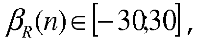
- X-coordinate
- describes the X-coordinate of the intersection point of the strut skeleton line with a cutting plane in an xy-coordinate system in the cutting plane
- Y-coordinate
- describes the Y-coordinate of the intersection point of the strut skeleton line with a cutting plane in an xy-coordinate system in the cutting plane
- n
- describes a currently viewed profile section
- nmax
- describes how many equidistant profile sections the strut and the wing element are divided into over their radial extension; where
- αs(n)
- describes a sickle angle at the profile section n of the wing element, ie an angle between a first leg displaced parallel to the axis of rotation and a second leg, which is defined by the points of the leading and trailing edges of the strut in the cutting plane;
- DH
- describes the outer diameter of the motor mount (3);
- LP
- describes the profile length of the strut (10), ie the distance between the front and rear edges of the strut in the cutting plane;
- βs(n)
- describes a correction factor of the sickle, where
- βR(n)
- describes a correction factor of the profile rotation, where
Die in
Des Weiteren ist das sog. 10-dB-Kriterium angegeben, welches mit einem Abstand von 10 dB unterhalb des Summenpegels verläuft. Das 10-dB-Kriterium ist insbesondere für die Bewertung des Klangbildes eines Lüftergeräusches relevant: Das 10-dB-Kriterium besagt, dass diejenigen Frequenzanteile, welche unterhalb dieses 10-dB-Kriteriums liegen, nicht als störend wahrgenommen werden. Man kann sich das so vorstellen, wie in einem Großraumbüro, wo einzelne Stimmen in einem allgemeinen Gemurmel untergehen. Im Umkehrschluss werden Geräuschanteile, welche dieses 10-dB-Kriterium verletzen, als besonders störend wahrgenommen. Verlaufen alle Frequenzanteile unterhalb des 10-dB-Kriteriums wird die Geräuschabstrahlung als angenehmes, "sattes" Brummen wahrgenommen.Furthermore, the so-called 10 dB criterion is specified, which runs at a distance of 10 dB below the total level. The 10 dB criterion is particularly relevant for evaluating the sound of a fan noise: The 10 dB criterion states that those frequency components that are below this 10 dB criterion are not perceived as disturbing. You can imagine it as in an open-plan office, where individual voices are drowned out by the general murmur. Conversely, noise components that violate this 10 dB criterion are perceived as particularly disturbing. If all frequency components are below the 10 dB criterion, the noise radiation is perceived as a pleasant, "rich" hum.
Die abgebildeten
Die Streben können beispielsweise auf der Druckseite und/oder auf der Unterdruckseite vorgesehen sein.The struts can, for example, be provided on the pressure side and/or on the vacuum side.
- 11
- KühlerlüftermodulRadiator fan module
- 22
- LüfterzargeFan frame
- 33
- MotorhalterEngine mount
- 44
- LüfterradausnehmungFan wheel recess
- 55
- LüfterradFan wheel
- 5a5a
- FlügelelementeWing elements
- 1010
- Strebestrut
- 1111
- VerstärkungReinforcement
- 1212
- SkelettlinieSkeleton line
- 1313
- Scheitel der SkelettlinieVertex of the skeletal line
- 1414
- Erstreckungsvektor der Strebe im Austrittspunkt der Strebe aus dem MotorhalterExtension vector of the strut at the exit point of the strut from the engine mount
- 1515
- Radialenvektor durch den Austrittspunkt der Strebe aus dem MotorhalterRadial vector through the exit point of the strut from the engine mount
- 1616
- Erstreckungsvektor der Strebe im Eintrittspunkt der Strebe in die LüfterzargeExtension vector of the strut at the entry point of the strut into the fan frame
- 16a16a
- Radialenvektor durch den Eintrittspunkt der Strebe in die LüfterzargeRadial vector through the entry point of the strut into the fan shroud
- 1717
- StartpunktStarting point
- 1818
- EndpunktEndpoint
- 1919
- VerstärkungswandReinforcing wall
- 2020
- Profilprofile
- 2121
- Profilwölbung der OberseiteProfile curvature of the top
- 2222
- Profilwölbung der UnterseiteProfile curvature of the underside
- 2323
- ProfildickeProfile thickness
- 2424
- NasenradiusNose radius
- 2525
- ProfiltiefeTread depth
- 2626
- VorderkanteFront edge
- 2727
- HinterkanteTrailing edge
- 2828
- Lotrechte zum MotorhalterPerpendicular to the engine mount
- 2929
- Richtung der LuftströmungDirection of air flow
- 3030
- BefestigungsschnittstelleMounting interface
- 3131
- Armierungreinforcement
- 100100
- vorbekannte, geradlinige Strebenpreviously known, straight struts
- 11
- ProfillängeProfile length
- r2r2
- Radius OberseitenkrümmungRadius top curvature
- r3r3
- Radius UnterseitenkrümmungRadius bottom curvature
- hH
- HöheHeight
- d1d1
- ProfilnasendurchmesserProfile nose diameter
- d2d2
- HinterkantendurchmesserTrailing edge diameter
- RR
- RotationsachseRotation axis
- αα
- AnstellwinkelAngle of attack
- ββ
- Winkelangle
- ϕϕ
- Winkelangle
Claims (10)
- Cooling fan module (1) comprising:a fan shroud (2);a fan propeller cutout (4), which is formed in the fan shroud (2);a motor mount (3) which is mechanically connected to the fan shroud (2) by means of struts (10) which are located at the rear viewed in the flow direction;a motor, in particular electric motor (5), which is mounted at least partially in the motor mount (3);a fan propeller (6) which is arranged in the fan propeller cutout (4) and which is driven rotationally about a rotational axis (R) by the motor (5), wherein the fan propeller has a plurality of blade elements (6a),wherein at least all the elements of a group which has at least one of the struts (10) and at least one of the blade elements (6a) are forward-sickled or rearward-sickled,wherein a blade element mean line of at least one of the blade elements (6a) of the group and a strut mean line of the struts (10) of the group in a profile section are related to one another such that the geometry of the at least one strut (10) of the group follows at least essentially the geometry of the at least one blade element (6a) of the group with respect to the extent in a plane perpendicular to the rotational axis (R),characterized in thatthe cooling fan module (1) has exactly two struts (10) more than blade elements (6a).
- Cooling fan module according to Claim 1, wherein the group comprises a plurality, in particular all, of the struts and/or a plurality, in particular all, of the blade elements (6a).
- Cooling fan module according to Claim 1 or 2, wherein the cooling fan module (1) has eleven struts and nine blade elements.
- Cooling fan module according to one of the preceding claims, wherein the struts (10) have a semi-symmetrical aerofoil profile.
- Cooling fan module according to one of the preceding claims, wherein the struts (10) are arranged with respect to the rotational axis (R) at a blade angle α in the range between 5 degrees and 45 degrees, preferably between 10 degrees and 25 degrees.
- Cooling fan module according to one of the preceding claims, wherein the struts (10) emerge from the motor mount (3) at an angle β which has a value in the range from -30° to +30°.
- Cooling fan module according to one of the preceding claims, wherein the struts (10) enter the fan shroud (2) at a predefined angle ϕ which has a value in the range from -90° to +30°.
- Cooling fan module according to one of the preceding claims, wherein a strengthening element (11) is provided which is formed between the motor mount (3) and one of the struts (10).
- Cooling fan module according to one of the preceding claims, wherein the fan shroud (2), the motor mount (3) and the struts (10) are formed as a single-piece plastics injection mould part.
- Cooling fan module according to one of the preceding claims, wherein the struts (10) have a reinforcement element (31).
Applications Claiming Priority (1)
| Application Number | Priority Date | Filing Date | Title |
|---|---|---|---|
| DE102017126823.5A DE102017126823A1 (en) | 2017-11-15 | 2017-11-15 | Cooling fan module |
Publications (2)
| Publication Number | Publication Date |
|---|---|
| EP3486499A1 EP3486499A1 (en) | 2019-05-22 |
| EP3486499B1 true EP3486499B1 (en) | 2024-05-01 |
Family
ID=64267546
Family Applications (1)
| Application Number | Title | Priority Date | Filing Date |
|---|---|---|---|
| EP18204663.1A Active EP3486499B1 (en) | 2017-11-15 | 2018-11-06 | Cooler ventilation module |
Country Status (7)
| Country | Link |
|---|---|
| US (1) | US10989055B2 (en) |
| EP (1) | EP3486499B1 (en) |
| JP (2) | JP2019105269A (en) |
| KR (1) | KR102296564B1 (en) |
| CN (1) | CN110030211B (en) |
| DE (1) | DE102017126823A1 (en) |
| MX (1) | MX2018013960A (en) |
Families Citing this family (7)
| Publication number | Priority date | Publication date | Assignee | Title |
|---|---|---|---|---|
| DE102017126823A1 (en) * | 2017-11-15 | 2019-05-16 | Brose Fahrzeugteile GmbH & Co. Kommanditgesellschaft, Würzburg | Cooling fan module |
| DE102018214782A1 (en) * | 2018-08-30 | 2020-03-05 | Brose Fahrzeugteile GmbH & Co. Kommanditgesellschaft, Würzburg | Fan frame of a motor vehicle |
| US10995772B2 (en) * | 2019-03-21 | 2021-05-04 | Cnh Industrial America Llc | Agricultural harvester cooler box with debris guard |
| CN111677689A (en) * | 2020-06-23 | 2020-09-18 | 东方电气集团东方电机有限公司 | Design method of vibration and noise reduction mixed flow pump or axial flow pump |
| US11448231B2 (en) | 2020-07-21 | 2022-09-20 | Brose Fahrzeugteile SE & Co. Kommanditgesellschaft, Würzburg | Cooling fan module |
| CN112797026A (en) * | 2020-12-30 | 2021-05-14 | 上海马陆日用友捷汽车电气有限公司 | Axial-flow type cooling fan matched with family car |
| US11713679B1 (en) * | 2022-01-27 | 2023-08-01 | Raytheon Technologies Corporation | Tangentially bowed airfoil |
Family Cites Families (34)
| Publication number | Priority date | Publication date | Assignee | Title |
|---|---|---|---|---|
| JPS57186097A (en) * | 1981-05-13 | 1982-11-16 | Hitachi Ltd | Axial-flow fan |
| JPS62265499A (en) * | 1986-05-13 | 1987-11-18 | Mitsubishi Heavy Ind Ltd | Axial fan with moving blade of variable |
| DE4020952A1 (en) | 1990-06-30 | 1992-01-02 | Bosch Gmbh Robert | Rotating fan with sickle-shaped blades - has each blade made with curved recess in leading edge near root |
| DE4222264C2 (en) * | 1992-07-07 | 1997-08-21 | Temic Auto Electr Motors Gmbh | Cooling device for a motor vehicle |
| DE69529379T2 (en) * | 1994-09-29 | 2003-10-09 | Valeo Thermique Moteur Le Mesn | Fan |
| US5582507A (en) * | 1994-09-29 | 1996-12-10 | Valeo Thermique Moteur | Automotive fan structure |
| US5961289A (en) | 1995-11-22 | 1999-10-05 | Deutsche Forshungsanstalt Fur Luft-Und Raumfahrt E.V. | Cooling axial flow fan with reduced noise levels caused by swept laminar and/or asymmetrically staggered blades |
| DE19638518A1 (en) * | 1996-09-20 | 1998-04-02 | Distelkamp Stroemungstechnik | Axial impeller for cooling motor vehicle IC engine |
| EP0945627B1 (en) * | 1998-03-23 | 2004-01-02 | SPAL S.r.l. | Axial flow fan |
| IT1304683B1 (en) * | 1998-10-08 | 2001-03-28 | Gate Spa | AIR CONVEYOR FOR AN ELECTRIC FAN, ESPECIALLY FOR A MOTOR VEHICLE RADIATOR. |
| TW488497U (en) * | 1999-03-02 | 2002-05-21 | Delta Electronics Inc | Supercharged fan stator for wind diversion |
| JP2002039098A (en) * | 2000-07-21 | 2002-02-06 | Atago Seisakusho:Kk | Duct of air blower |
| JP3978083B2 (en) * | 2001-06-12 | 2007-09-19 | 漢拏空調株式会社 | Axial fan |
| KR100761152B1 (en) | 2001-06-12 | 2007-09-21 | 한라공조주식회사 | Axial flow fan |
| TW523652B (en) * | 2001-08-01 | 2003-03-11 | Delta Electronics Inc | Combination fan and applied fan frame structure |
| KR100937929B1 (en) * | 2003-07-01 | 2010-01-21 | 한라공조주식회사 | Stator of Axial flow fan shroud |
| DE102005019421B4 (en) * | 2004-04-26 | 2014-02-13 | Behr Gmbh & Co. Kg | Fan cover for a heat exchanger, in particular for motor vehicles |
| EP1600640A3 (en) * | 2004-04-26 | 2009-11-04 | Behr GmbH & Co. KG | Fan shroud for a heat exchanger, in particular for vehicles. |
| JP2007192217A (en) * | 2005-12-19 | 2007-08-02 | Nippon Densan Corp | Axial-flow fan |
| US20070140844A1 (en) * | 2005-12-19 | 2007-06-21 | Nidec Corporation | Axial Flow Fan |
| US8197204B2 (en) * | 2005-12-23 | 2012-06-12 | Behr Gmbh & Co. Kg | Fan system, heat exchanger module, method for manufacturing a fan system and/or a heat exchanger module |
| DE102006062118A1 (en) * | 2005-12-23 | 2007-06-28 | Behr Gmbh & Co. Kg | Fan arrangement for heat exchanger, in particular for motor vehicles, has holder for fan drive unit connected to housing by struts part of whose surfaces are aligned to impeller axis to aid air flow |
| TWI398579B (en) * | 2009-12-18 | 2013-06-11 | Yen Sun Technology Corp | A cooling fan with reduced noise |
| DE102010032097A1 (en) * | 2010-07-23 | 2012-01-26 | Formtech Gmbh | Compressor blade of a gas turbine engine with self-sharpening leading edge structure |
| CN103649548B (en) * | 2011-06-14 | 2017-07-28 | 罗伯特·博世有限公司 | Air-flow component with improved acoustic characteristic |
| ITTO20110140U1 (en) * | 2011-12-15 | 2013-06-16 | Gate Srl | VENTILATION GROUP FOR A HEAT EXCHANGER, PARTICULARLY FOR A MOTOR VEHICLE |
| FR2989999B1 (en) * | 2012-04-26 | 2016-01-01 | Sdmo Ind | COOLING DEVICE COMPRISING AN AXIAL FAN WITH CENTRAL FLOW RECTIFICATION AND CORRESPONDING ELECTROGEN GROUP. |
| DE102012109545A1 (en) * | 2012-10-08 | 2014-04-10 | Ebm-Papst Mulfingen Gmbh & Co. Kg | "Housing for a fan or fan" |
| JP6229157B2 (en) * | 2013-12-04 | 2017-11-15 | パナソニックIpマネジメント株式会社 | Blower and outdoor unit equipped with the blower |
| FR3015379B1 (en) * | 2013-12-20 | 2017-06-09 | Valeo Systemes Thermiques | AUTOMOTIVE FAN HAVING A STATOR BEFORE THE PROPELLER |
| CN203926066U (en) | 2014-05-22 | 2014-11-05 | 浙江志江风机有限公司 | Wind Volume subtracts sound blower fan |
| CN108603512B (en) * | 2016-02-08 | 2021-03-12 | 罗伯特·博世有限公司 | Engine cooling fan shroud with unplugged outlets |
| DE102016203327A1 (en) | 2016-03-01 | 2017-09-07 | Röchling Automotive SE & Co. KG | Press-formed fan cowl, vehicle with such a fan cowl and method for producing such a fan cowl |
| DE102017126823A1 (en) * | 2017-11-15 | 2019-05-16 | Brose Fahrzeugteile GmbH & Co. Kommanditgesellschaft, Würzburg | Cooling fan module |
-
2017
- 2017-11-15 DE DE102017126823.5A patent/DE102017126823A1/en active Pending
-
2018
- 2018-11-01 JP JP2018206263A patent/JP2019105269A/en active Pending
- 2018-11-06 EP EP18204663.1A patent/EP3486499B1/en active Active
- 2018-11-14 MX MX2018013960A patent/MX2018013960A/en unknown
- 2018-11-14 US US16/190,414 patent/US10989055B2/en active Active
- 2018-11-14 KR KR1020180140292A patent/KR102296564B1/en active IP Right Grant
- 2018-11-15 CN CN201811359171.8A patent/CN110030211B/en active Active
-
2021
- 2021-07-15 JP JP2021117384A patent/JP2021165556A/en active Pending
Also Published As
| Publication number | Publication date |
|---|---|
| US20190353083A1 (en) | 2019-11-21 |
| DE102017126823A1 (en) | 2019-05-16 |
| EP3486499A1 (en) | 2019-05-22 |
| KR102296564B1 (en) | 2021-08-31 |
| CN110030211B (en) | 2020-10-27 |
| US10989055B2 (en) | 2021-04-27 |
| JP2019105269A (en) | 2019-06-27 |
| JP2021165556A (en) | 2021-10-14 |
| MX2018013960A (en) | 2019-05-16 |
| KR20190055764A (en) | 2019-05-23 |
| CN110030211A (en) | 2019-07-19 |
Similar Documents
| Publication | Publication Date | Title |
|---|---|---|
| EP3486499B1 (en) | Cooler ventilation module | |
| EP3450717B1 (en) | Fan wheel | |
| DE69919672T2 (en) | Stator for axial fans | |
| DE69827764T2 (en) | CENTRIFUGAL FAN, MANUFACTURING METHOD AND AIR CONDITIONING WITH SUCH A FAN | |
| DE69724868T2 (en) | Multi-blade rotor for centrifugal fans | |
| DE2756880C2 (en) | Axial fan | |
| EP3289223B1 (en) | Diagonal or radial fan having a guide device | |
| EP2823184B1 (en) | Axial fan | |
| EP1759091B1 (en) | Turbine wheel in a waste gas turbine of a waste gas turbocharger | |
| DE3137114A1 (en) | AXIAL BLOWERS, ESPECIALLY FOR MOTOR VEHICLES | |
| DE112014001308T5 (en) | Axial fan assembly with free blade tips | |
| DE102008050848A1 (en) | ring generator | |
| EP3450716B1 (en) | Fan wheel and cooling fan module comprising such a fan wheel | |
| DE2756800A1 (en) | AXIAL FAN WITH AUXILIARY BLADES | |
| EP1387053A1 (en) | Fan arrangement for cooling of motor vehicle engines | |
| DE102008000168A1 (en) | Blower arrangement with pre-swirl generator | |
| DE2939385A1 (en) | Centrifugal blower for car heating - has impeller with central entry on one side and openings, giving cooling air flow over motor, on other | |
| DE19710606B4 (en) | Fans, in particular for radiators of internal combustion engines | |
| DE102017012255A1 (en) | Cooling fan module | |
| DE102018211809A1 (en) | Housing for a fan and fan | |
| EP3617529B1 (en) | Fan frame of a motor vehicle | |
| WO2020152211A1 (en) | Impeller of a motor vehicle | |
| DE60128616T2 (en) | Fan for a motor vehicle with vanes | |
| DE102019213315A1 (en) | fan | |
| EP4345277A2 (en) | A swirler, an aerodynamic profile, and a method of manufacturing a swirler |
Legal Events
| Date | Code | Title | Description |
|---|---|---|---|
| PUAI | Public reference made under article 153(3) epc to a published international application that has entered the european phase |
Free format text: ORIGINAL CODE: 0009012 |
|
| STAA | Information on the status of an ep patent application or granted ep patent |
Free format text: STATUS: THE APPLICATION HAS BEEN PUBLISHED |
|
| AK | Designated contracting states |
Kind code of ref document: A1 Designated state(s): AL AT BE BG CH CY CZ DE DK EE ES FI FR GB GR HR HU IE IS IT LI LT LU LV MC MK MT NL NO PL PT RO RS SE SI SK SM TR |
|
| AX | Request for extension of the european patent |
Extension state: BA ME |
|
| STAA | Information on the status of an ep patent application or granted ep patent |
Free format text: STATUS: REQUEST FOR EXAMINATION WAS MADE |
|
| 17P | Request for examination filed |
Effective date: 20191122 |
|
| RBV | Designated contracting states (corrected) |
Designated state(s): AL AT BE BG CH CY CZ DE DK EE ES FI FR GB GR HR HU IE IS IT LI LT LU LV MC MK MT NL NO PL PT RO RS SE SI SK SM TR |
|
| RAP1 | Party data changed (applicant data changed or rights of an application transferred) |
Owner name: BROSE FAHRZEUGTEILE SE & CO. KOMMANDITGESELLSCHAFT, WUERZBURG |
|
| STAA | Information on the status of an ep patent application or granted ep patent |
Free format text: STATUS: EXAMINATION IS IN PROGRESS |
|
| 17Q | First examination report despatched |
Effective date: 20220331 |
|
| GRAP | Despatch of communication of intention to grant a patent |
Free format text: ORIGINAL CODE: EPIDOSNIGR1 |
|
| STAA | Information on the status of an ep patent application or granted ep patent |
Free format text: STATUS: GRANT OF PATENT IS INTENDED |
|
| RIC1 | Information provided on ipc code assigned before grant |
Ipc: F04D 19/00 20060101ALI20231115BHEP Ipc: F04D 29/66 20060101ALI20231115BHEP Ipc: F04D 29/38 20060101ALI20231115BHEP Ipc: F01P 5/02 20060101ALI20231115BHEP Ipc: F01P 5/06 20060101ALI20231115BHEP Ipc: F04D 29/54 20060101AFI20231115BHEP |
|
| INTG | Intention to grant announced |
Effective date: 20231206 |
|
| GRAS | Grant fee paid |
Free format text: ORIGINAL CODE: EPIDOSNIGR3 |
|
| GRAA | (expected) grant |
Free format text: ORIGINAL CODE: 0009210 |
|
| STAA | Information on the status of an ep patent application or granted ep patent |
Free format text: STATUS: THE PATENT HAS BEEN GRANTED |
|
| AK | Designated contracting states |
Kind code of ref document: B1 Designated state(s): AL AT BE BG CH CY CZ DE DK EE ES FI FR GB GR HR HU IE IS IT LI LT LU LV MC MK MT NL NO PL PT RO RS SE SI SK SM TR |
|
| REG | Reference to a national code |
Ref country code: GB Ref legal event code: FG4D Free format text: NOT ENGLISH |