EP3486420A2 - Method for positioning a window or a door - Google Patents
Method for positioning a window or a door Download PDFInfo
- Publication number
- EP3486420A2 EP3486420A2 EP18206244.8A EP18206244A EP3486420A2 EP 3486420 A2 EP3486420 A2 EP 3486420A2 EP 18206244 A EP18206244 A EP 18206244A EP 3486420 A2 EP3486420 A2 EP 3486420A2
- Authority
- EP
- European Patent Office
- Prior art keywords
- window
- spindle
- threaded spindle
- door
- spindle nut
- Prior art date
- Legal status (The legal status is an assumption and is not a legal conclusion. Google has not performed a legal analysis and makes no representation as to the accuracy of the status listed.)
- Granted
Links
- 238000000034 method Methods 0.000 title description 3
- 230000008878 coupling Effects 0.000 claims abstract description 57
- 238000010168 coupling process Methods 0.000 claims abstract description 57
- 238000005859 coupling reaction Methods 0.000 claims abstract description 57
- 125000006850 spacer group Chemical group 0.000 claims abstract description 48
- 238000012360 testing method Methods 0.000 claims description 8
- 241000238633 Odonata Species 0.000 claims description 7
- 239000011295 pitch Substances 0.000 claims description 3
- 238000006073 displacement reaction Methods 0.000 abstract description 6
- 230000002093 peripheral effect Effects 0.000 abstract description 2
- 238000009434 installation Methods 0.000 description 9
- 210000002105 tongue Anatomy 0.000 description 4
- 238000003780 insertion Methods 0.000 description 3
- 230000037431 insertion Effects 0.000 description 3
- 230000000295 complement effect Effects 0.000 description 1
- 239000012141 concentrate Substances 0.000 description 1
- 238000010276 construction Methods 0.000 description 1
- 230000001419 dependent effect Effects 0.000 description 1
- 238000013461 design Methods 0.000 description 1
- 238000011161 development Methods 0.000 description 1
- 230000018109 developmental process Effects 0.000 description 1
- 238000005187 foaming Methods 0.000 description 1
- 238000004519 manufacturing process Methods 0.000 description 1
- 239000000463 material Substances 0.000 description 1
Images


Classifications
-
- E—FIXED CONSTRUCTIONS
- E06—DOORS, WINDOWS, SHUTTERS, OR ROLLER BLINDS IN GENERAL; LADDERS
- E06B—FIXED OR MOVABLE CLOSURES FOR OPENINGS IN BUILDINGS, VEHICLES, FENCES OR LIKE ENCLOSURES IN GENERAL, e.g. DOORS, WINDOWS, BLINDS, GATES
- E06B1/00—Border constructions of openings in walls, floors, or ceilings; Frames to be rigidly mounted in such openings
- E06B1/56—Fastening frames to the border of openings or to similar contiguous frames
- E06B1/60—Fastening frames to the border of openings or to similar contiguous frames by mechanical means, e.g. anchoring means
- E06B1/6015—Anchoring means
- E06B1/6023—Anchoring means completely hidden between the frame and the border of the opening, at least part of the means being previously fixed to the wall
- E06B1/603—Anchoring means completely hidden between the frame and the border of the opening, at least part of the means being previously fixed to the wall adjustable
-
- E—FIXED CONSTRUCTIONS
- E04—BUILDING
- E04F—FINISHING WORK ON BUILDINGS, e.g. STAIRS, FLOORS
- E04F21/00—Implements for finishing work on buildings
- E04F21/0007—Implements for finishing work on buildings for mounting doors, windows or frames; their fitting
- E04F21/0015—Implements for finishing work on buildings for mounting doors, windows or frames; their fitting for mounting frames
-
- E—FIXED CONSTRUCTIONS
- E06—DOORS, WINDOWS, SHUTTERS, OR ROLLER BLINDS IN GENERAL; LADDERS
- E06B—FIXED OR MOVABLE CLOSURES FOR OPENINGS IN BUILDINGS, VEHICLES, FENCES OR LIKE ENCLOSURES IN GENERAL, e.g. DOORS, WINDOWS, BLINDS, GATES
- E06B1/00—Border constructions of openings in walls, floors, or ceilings; Frames to be rigidly mounted in such openings
- E06B1/56—Fastening frames to the border of openings or to similar contiguous frames
- E06B1/60—Fastening frames to the border of openings or to similar contiguous frames by mechanical means, e.g. anchoring means
- E06B1/6015—Anchoring means
-
- E—FIXED CONSTRUCTIONS
- E06—DOORS, WINDOWS, SHUTTERS, OR ROLLER BLINDS IN GENERAL; LADDERS
- E06B—FIXED OR MOVABLE CLOSURES FOR OPENINGS IN BUILDINGS, VEHICLES, FENCES OR LIKE ENCLOSURES IN GENERAL, e.g. DOORS, WINDOWS, BLINDS, GATES
- E06B1/00—Border constructions of openings in walls, floors, or ceilings; Frames to be rigidly mounted in such openings
- E06B1/56—Fastening frames to the border of openings or to similar contiguous frames
- E06B1/60—Fastening frames to the border of openings or to similar contiguous frames by mechanical means, e.g. anchoring means
- E06B1/6069—Separate spacer means acting exclusively in the plane of the opening; Shims; Wedges; Tightening of a complete frame inside a wall opening
- E06B1/6076—Separate spacer means acting exclusively in the plane of the opening; Shims; Wedges; Tightening of a complete frame inside a wall opening of screw-type
-
- F—MECHANICAL ENGINEERING; LIGHTING; HEATING; WEAPONS; BLASTING
- F16—ENGINEERING ELEMENTS AND UNITS; GENERAL MEASURES FOR PRODUCING AND MAINTAINING EFFECTIVE FUNCTIONING OF MACHINES OR INSTALLATIONS; THERMAL INSULATION IN GENERAL
- F16B—DEVICES FOR FASTENING OR SECURING CONSTRUCTIONAL ELEMENTS OR MACHINE PARTS TOGETHER, e.g. NAILS, BOLTS, CIRCLIPS, CLAMPS, CLIPS OR WEDGES; JOINTS OR JOINTING
- F16B21/00—Means for preventing relative axial movement of a pin, spigot, shaft or the like and a member surrounding it; Stud-and-socket releasable fastenings
- F16B21/06—Releasable fastening devices with snap-action
- F16B21/08—Releasable fastening devices with snap-action in which the stud, pin, or spigot has a resilient part
- F16B21/086—Releasable fastening devices with snap-action in which the stud, pin, or spigot has a resilient part the shank of the stud, pin or spigot having elevations, ribs, fins or prongs intended for deformation or tilting predominantly in a direction perpendicular to the direction of insertion
-
- F—MECHANICAL ENGINEERING; LIGHTING; HEATING; WEAPONS; BLASTING
- F16—ENGINEERING ELEMENTS AND UNITS; GENERAL MEASURES FOR PRODUCING AND MAINTAINING EFFECTIVE FUNCTIONING OF MACHINES OR INSTALLATIONS; THERMAL INSULATION IN GENERAL
- F16B—DEVICES FOR FASTENING OR SECURING CONSTRUCTIONAL ELEMENTS OR MACHINE PARTS TOGETHER, e.g. NAILS, BOLTS, CIRCLIPS, CLAMPS, CLIPS OR WEDGES; JOINTS OR JOINTING
- F16B5/00—Joining sheets or plates, e.g. panels, to one another or to strips or bars parallel to them
- F16B5/02—Joining sheets or plates, e.g. panels, to one another or to strips or bars parallel to them by means of fastening members using screw-thread
- F16B5/0216—Joining sheets or plates, e.g. panels, to one another or to strips or bars parallel to them by means of fastening members using screw-thread the position of the plates to be connected being adjustable
- F16B5/0233—Joining sheets or plates, e.g. panels, to one another or to strips or bars parallel to them by means of fastening members using screw-thread the position of the plates to be connected being adjustable allowing for adjustment perpendicular to the plane of the plates
-
- F—MECHANICAL ENGINEERING; LIGHTING; HEATING; WEAPONS; BLASTING
- F16—ENGINEERING ELEMENTS AND UNITS; GENERAL MEASURES FOR PRODUCING AND MAINTAINING EFFECTIVE FUNCTIONING OF MACHINES OR INSTALLATIONS; THERMAL INSULATION IN GENERAL
- F16B—DEVICES FOR FASTENING OR SECURING CONSTRUCTIONAL ELEMENTS OR MACHINE PARTS TOGETHER, e.g. NAILS, BOLTS, CIRCLIPS, CLAMPS, CLIPS OR WEDGES; JOINTS OR JOINTING
- F16B5/00—Joining sheets or plates, e.g. panels, to one another or to strips or bars parallel to them
- F16B5/02—Joining sheets or plates, e.g. panels, to one another or to strips or bars parallel to them by means of fastening members using screw-thread
- F16B5/025—Joining sheets or plates, e.g. panels, to one another or to strips or bars parallel to them by means of fastening members using screw-thread specially designed to compensate for misalignement or to eliminate unwanted play
Definitions
- the present invention relates to an apparatus for positioning a window or a door in a building opening, comprising at least one spacer element having a coupling portion for coupling with the window or the door and an abutment portion formed for abutment with a border of the building opening, wherein for a Displacement of the window or the door within the building opening an adjusting device is provided, by means of which the contact portion is adjustable relative to the coupling portion in and against an adjustment direction.
- the installation of windows and doors in structures is relatively time consuming and cumbersome, because it is important to ensure an exact horizontal and vertical alignment and in general, the width of the joint between the window frame or the door and the border of the building opening are within a predetermined tolerance range should.
- the support and positioning of windows and doors during installation can be done by means of blocks or wedges, which are moved against each other for height adjustment. The handling of the blocks or wedges is difficult, especially in large and therefore heavy windows and doors.
- the adjusting device has a first threaded spindle extending along the displacement direction, which can be supported in or against the adjustment direction on the coupling section or on the contact section and cooperates with a first spindle nut which can be supported in the opposite direction on the other element of coupling section and contact section.
- the distance between the coupling section and the contact section predetermined by the spacer element can be changed. If the frame of the window to be installed or the door to be installed is supported by one or more spacer elements according to the invention at the bottom of the building opening, can thus quickly and easily make a height adjustment of the window by turning the first threaded spindle or the first spindle nut. In the case of a support of the frame at two spaced locations can also be adjusted by different height adjustment, the horizontal inclination of the window or the door. Similarly, the lateral position of the window or door may be adjusted by means of one or more laterally inserted spacer elements according to the invention. After positioning, the window or door can be secured in the building opening, for example by screwing. The spacer elements can remain in the gap between the window or the door and the border of the building opening and be foamed, for example.
- the rotation of a spindle nut relative to a threaded spindle is much faster and easier to accomplish than, for example, moving wedges or blocks against each other.
- the spindle drive formed by the threaded spindle and the spindle nut allows a particularly exact position adjustment.
- the invention facilitates the installation of windows having a frame and a wing movable relative thereto.
- a device according to the invention or several devices according to the invention the installation of such a window can be carried out with the sash closed, because the fitter does not have to reach through the window opening or reach around the window frame profile.
- a correct orientation of the wing is ensured relative to the frame.
- there may be a relative distortion between the frame and the sash which in the worst case leads to striking, rubbing or jamming of the sash during the closing process.
- first spindle nut does not have to be in the form of a conventional nut. Rather, each component is to be regarded as a spindle nut which has an internal thread which fits to the external thread of the threaded spindle. Depending on the embodiment, either the spindle nut or the threaded spindle can be acted upon in rotation to actuate the adjusting device.
- the coupling section does not necessarily have to be attachable to the window or door. Rather, the coupling portion may in principle be designed for mere application to a frame profile of the window or the door. Such application is also to be regarded as "coupling" in the sense of the present disclosure.
- a supportability of the first threaded spindle on the coupling portion or on the abutment portion may also be given by a one-piece design of the threaded spindle with the coupling portion or the abutment portion. The same applies to the supportability of the first spindle nut on the other element of the coupling section and contact section.
- the adjustment direction preferably extends in the wing plane of the window or the door when the spacer is coupled to the window or the door and optionally the wing is closed.
- an actuating portion for a direct manual rotation of the first threaded spindle relative to the first spindle nut by a user is provided on the first threaded spindle and / or on the first spindle nut.
- the manual twisting can be done without tools or with the help of a tool such as a fork wrench.
- an embodiment of the invention provides that the actuating portion has a gripping feature and / or a positive locking feature, in particular a corrugation and / or a square profile. While, for example, a corrugation is particularly suitable for a tool-free manual actuation of the adjustment, allows a edge profile such as a hexagonal profile easy operation by means of a corresponding tool.
- the actuating portion may be formed integrally with the first threaded spindle or with the first spindle nut. Preferably, it is therefore the first threaded spindle or the first spindle nut itself, which is to be rotated by a user. This allows a particularly intuitive operation of the adjustment. In principle, however, the actuating portion may also be provided on a separate component, which is rotatably coupled to the first threaded spindle or with the first spindle nut.
- the abutment portion may comprise a support plate. This can easily be brought into contact with the side, top or bottom of a building opening.
- the contact section could also be shaped in a complex manner, if, for example, a corresponding complementary shape is formed in the region of the border of the building opening.
- An embodiment of the invention provides that the first threaded spindle cooperates with a lock nut provided for locking the first spindle nut.
- a lock nut provided for locking the first spindle nut.
- the lock nut can have an actuation section for direct manual twisting, that is, for example, a grip feature and / or a positive locking feature.
- a further embodiment of the invention provides that the adjusting device has a second threaded spindle which extends along the adjustment direction and cooperates with a second spindle nut such that both by a rotation of the first spindle nut relative to the first threaded spindle and by a rotation of the second spindle nut relative to the second threaded spindle of the abutment portion is adjustable relative to the coupling portion in and against the adjustment direction. The user can then selectively rotate the first spindle nut or the second spindle nut to actuate the adjusting device.
- the first spindle nut and / or the second spindle nut can be rotatably mounted relative to the coupling portion.
- a sliding bearing can be provided.
- the coupling section then does not have to be rotated during a rotation of the first spindle nut and / or the second spindle nut, so that it can be fixedly attached to the window or the door accordingly.
- the first threaded spindle and the second threaded spindle preferably have different thread pitches. This allows a different pitch adjustment, depending on which of the two spindle nuts is rotated.
- first threaded spindle can have a standard thread and the second threaded spindle can have a fine thread, or vice versa.
- a spindle nut can then be used for a coarse adjustment and the other spindle nut for a fine adjustment.
- the positioning of a window or a door in a building opening can be further simplified.
- the coupling section, the contact section, the first threaded spindle and / or the first spindle nut is made of a plastic, in particular of a regranulate, is / are.
- the corresponding spacer element can be manufactured particularly cost-effectively, so that it can be handled as a disposable article.
- the coupling portion may be formed for a positive or non-positive connection, in particular for a latching, snap or clip connection, with a window frame profile of the window or the door.
- the spacer can then be easily attached to the window or door before installation. In particular, it is possible in a simple manner to deliver windows and doors already with attached spacer elements. A laborious insertion of spacers between the frame and the border of the building opening is then not required.
- the coupling portion has at least one resilient latching element for engaging behind a profile projection provided on the frame profile.
- Profile projections are available in many common frame profiles.
- the resilient latching element can be designed as a latching tongue or as a latching hook.
- the coupling portion may have a shaft which is designed for insertion into a receptacle provided on the frame profile. Since the coupling portion is here after assembly at least partially within the frame profile, a particularly low height is achieved.
- the spacer element may have a passage for a fastening means which extends from the coupling section to the contact section through the entire spacer element.
- the final attachment of the window or the door to the masonry can be done in this embodiment by the spacer element.
- a screw can be passed through the frame profile and the spacer element into the masonry.
- no additional components such as angle, plates or the like are required.
- a form-fitting feature in particular an edge profile, is formed on the first threaded spindle or on the first spindle nut, which is accessible through a recess of the coupling portion.
- a subsequent position adjustment is possible - even if the gap between the frame and the masonry is already closed or covered.
- the coupling section and the contact section can communicate with each other via a joint, in particular via a ball joint. As a result, alignment tolerances, bumps and the like can be compensated.
- a device according to the invention may comprise a set of two, preferably at least four, spacer elements as described above having respective first threaded spindles and respective first spindle nuts. This allows positioning in multiple directions.
- the invention also relates to an apparatus for positioning a window or door in a building opening, having at least one inclination tester to be brought into contact with the window or the door and the inclination of the window brought into contact with or in contact therewith displayed door relative to a vertical plane and / or relative to a horizontal plane.
- a tilt tester usually a portable spirit level is used, which is applied to a flat surface of the window or the door and removed after checking again and put away.
- a portable spirit level is used, which is applied to a flat surface of the window or the door and removed after checking again and put away.
- the inclination checking device has fastening means for a detachable or permanent fastening of the inclination checking device to the window or the door.
- the inclination test device can be fastened to the window or the door, it does not have to be held during the positioning process.
- the user can concentrate entirely on the slope change of the window or the door, for example by means of a positioning device designed as described above.
- the correct position installation of windows of doors is considerably simplified.
- a device for positioning a window or door in a building opening comprising at least one spacer as described above, and additionally at least one inclination tester with attachment means for releasably or permanently attaching the inclination tester to the window or door.
- the inclination testing device may comprise at least one dragonfly, preferably two differently oriented dragonflies.
- the inclination tester is thus designed as a spirit level, which can be attached to the window or door.
- dragonflies work batteryless and are also available at low cost.
- the fastening means for a positive or non-positive connection in particular for a latching, snap or clip connection, are formed with a window frame profile of the window or the door. This allows a particularly quick and easy attachment of the tilt test device on the window or door.
- the inclination testing device can be arranged on an elongate basic body. This allows a particularly reliable and accurate tilt test, because the tilt tester is in the mounted state over a relatively large area with the window frame profile of the window or the door in contact.
- the main body may comprise a bar with a length of at least 20 cm, preferably at least 40 cm.
- the base body is made of a plastic, in particular of a regranulate.
- a plastic in particular of a regranulate.
- This allows a particularly cost-effective production of the inclination tester, so that it is not a disadvantage if it is also installed, so for example, foamed.
- it is also possible to remove the inclination checking device from the window or the door after completion of the positioning operation for reuse.
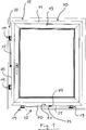
- window 10 comprises a frame 11 and a rotatable wing 13 and is intended for installation in a building opening 15.
- a positioning device 17 is provided, which will be described in more detail below.
- the positioning device 17 designed according to one embodiment of the invention comprises four spacer elements 19, of which two are arranged on the underside of the window frame 11 and two on the left side of the window frame 11, as shown.
- the window 10 is supported by the spacer elements 19 with respect to the border 20 of the building opening 15.
- the positioning device 17 comprises two inclination checking devices 25, one of which is arranged on the underside of the frame 11 and one on the left side of the frame 11 in the image.
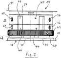
- Fig. 2 shows one of the spacer elements 19 in a side view.
- the spacer element 19 has an at least substantially cylindrical basic shape.
- the spacer element 19 can be fastened to the window frame 11 via a coupling section 27.
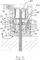
- 27 two resilient latching hooks 29 are provided on the coupling portion, as in the Section view according to Fig. 3 can be seen.
- the latching hooks 29 are arranged opposite as shown and engage behind respective profile projections 30 of the frame 11th
- the coupling portion 27 is supported on the border 20 of the building opening 15 via a first threaded spindle 31, a first spindle nut 32 cooperating therewith, a second threaded spindle 33, a second spindle nut 34 cooperating therewith and a contact portion 35.
- the abutment portion 35 is a support plate 37 having a flat abutment surface 38. On the support plate 37, a ball head 39 is formed, which is received in a ball head receptacle 40 of the spacer element 19. The coupling portion 27 and the abutment portion 35 are thus connected via a ball joint 41 with each other.
- the ball head receptacle 40 is formed in that component which also carries the first threaded spindle 31.
- the first spindle nut 32 is integrally formed with the second threaded spindle 33 as shown.
- the second spindle nut 34 is slidably supported on the coupling portion 27.
- the first threaded spindle 31 cooperates not only with the first spindle nut 32 but also with a lock nut 43 arranged adjacent thereto.
- Fig. 3 shows a state in which the first spindle nut 32 is turned up to the stop on the first threaded spindle 31 and equally the second spindle nut 34 is turned up to the stop on the second threaded spindle 33.
- the predetermined by the spacer element 19 distance between the coupling portion 27 and the contact portion 35 is minimal.
- the first spindle nut 32 is rotated relative to the first threaded spindle 31 so that it moves away from the stop, there is an increase in the distance between the coupling portion 27 and the abutment portion 35 and thus a shift Similarly, with a rotation of the second spindle nut 34 relative to the second threaded spindle 33 away from the stop a displacement of the frame 11 relative to the border 20 of the building opening 15 in the adjustment direction V takes place opposite the border 20 of the building opening 15.
- the first threaded spindle 31 and the first spindle nut 32 have a standard thread, while the second threaded spindle 33 and the second spindle nut 34 have a fine thread.
- the first spindle nut 32 and for a fine displacement of the frame 11, the second spindle nut 34 are rotated.
- the rotation of the spindle nuts 32, 34 can be done by direct manual means and in particular without tools, since the spindle nuts 32, 34 respective operating sections 44, 45 with handle features 46 (FIGS. Fig. 2 ) respectively.
- the lock nut 43 carries a peripheral corrugation 48.
- a user When positioning the window 10 within the building opening 15, a user can first make a coarse positioning by turning the first spindle nut 32 and then fix the position of the first spindle nut 32 by means of the lock nut 43. Then he can turn the second spindle nut 34 for fine positioning, wherein an undesired co-rotation of the first spindle nut 32 is prevented due to the lock nut 43.
- the lock nut 43 and the second spindle nut 34 are indicia 47 ( Fig. 2 ) are provided, which illustrate the sequence of steps in positioning.
- the spacer element 19 is provided for this purpose with a passage 80 for a screw 81.
- all components of the spacer element 19, in particular the coupling portion 27, the first threaded spindle 31, the first spindle nut 32, the second threaded spindle 33, the second spindle nut 34, the lock nut 43 and the support plate 37 made of a plastic, in particular from a regranulate ,
- the spacer element 19 can thus be manufactured particularly cost-effectively, so that it is suitable for use as a disposable article.
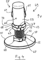
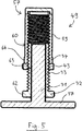
- the 4 to 6 show an alternative embodiment of a spacer element 49, which is constructed similar to that in the Fig. 1 to 3 shown spacer element 19, but designed for a lower height.
- the coupling portion 57 has a shaft 59 which, for insertion into a shank receptacle 58 provided on the frame 11 (FIG. Fig. 6 ) is trained.
- the shaft 57 has a cylindrical outer surface 60. From this stand two resilient latching tongues 61 ( Fig. 4 ). The resilient latching tongues 61 allow the coupling section 57 to snap into the shaft receptacle 58.
- spacer element 49 also has a first threaded spindle 31, a cooperating with this first spindle nut 32, a second threaded spindle 33, a cooperating with this second spindle nut 34, a lock nut 43 and a contact portion 35 in the form of a support plate 37.
- first threaded spindle 31 and the first spindle nut 32 have a fine thread
- second threaded spindle 33 and the second spindle nut 34 have a standard thread.
- the first threaded spindle 31 is formed integrally with the support plate 37.
- the second spindle nut 34 is further formed integrally with the shaft 59.
- the first spindle nut 32, the lock nut 43 and the second spindle nut 34 have respective actuating portions 62, 63, 64 which are provided with edge profiles 68. This allows twisting by means of a tool such as a fork wrench. Flags 47 are also provided. The adjustment of the second spindle nut 34 is to be made before the attachment of the coupling portion 57 on the window 10.
- the height of the in the 4 to 6 shown spacer element 49 is reduced in that the coupling portion 57 is partially disposed within the window frame 11 when the window 10 is installed.
- the edge profiles 68 require only a small height.
- Fig. 7 shows a further embodiment of a spacer element 69 of a positioning device 17 according to the invention.
- This is largely like the spacer element 49 according to 4 to 6 designed, however, wherein on the first screw 31, a form-fitting feature 83 is formed in the form of a hexagon socket, which is accessible through a recess 85 of the coupling portion 57. Since a corresponding recess 87 is also provided in the frame 11, the first threaded spindle 31 can also be rotated by means of a tool 88 if no lateral access to the gap between the frame 11 and the building opening 15 is possible.
- Each of the two inclination checking devices 25 comprises a strip-shaped main body 70, which is preferably made of a plastic, in particular of a regranulate. This has a flat contact surface 71 for applying the base body 70 to an outer surface of the frame 11. At the contact surface 71 are in Fig. 1 arranged invisible fasteners, which are in particular to similar latching hooks as in Fig. 3 for the spacer element 19 shown Snap hook 29 can act.
- the inclination test device 25 can be detachably attached to the frame 11.
- two dragonflies 75 are integrated, which are aligned offset by 90 ° to each other.
- the inclination of the window 10 can thus be continuously checked, without the need for a spirit level to be applied to the window frame 11 and held thereon.
- the inclination testers 25 are composed of inexpensive components, it is not absolutely necessary to remove them from the frame 11 before screwing and foaming the window 10. However, reuse of the tilt testers 25 may be desirable depending on the application. In principle, it is also possible to use a digital inclination indicator or the like instead of one or more dragonflies 75.
- the invention enables a considerably simplified installation of windows 10 and doors in building openings 15, wherein a particular advantage is that in a delivery of a window 10 with attached spacers 19, 49, 69 and inclination testing 25 in principle no own material and no own equipment must be provided by the fitter.
Abstract
Eine Vorrichtung zum Positionieren eines Fensters oder einer Tür in einer Gebäudeöffnung umfasst ein Distanzelement, das einen Kopplungsabschnitt für eine Kopplung mit dem Fenster oder der Tür und einen zum Anlegen an eine Umrandung der Gebäudeöffnung ausgebildeten Anlageabschnitt aufweist, wobei für eine Verschiebung des Fensters oder der Tür innerhalb der Gebäudeöffnung eine Verstelleinrichtung vorgesehen ist, mittels welcher der Anlageabschnitt relativ zu dem Kopplungsabschnitt in und entgegen einer Verstellrichtung verstellbar ist. Die Verstelleinrichtung weist eine sich entlang der Verstellrichtung erstreckende erste Gewindespindel auf, die in oder entgegen der Verstellrichtung am Kopplungsabschnitt oder am Anlageabschnitt abstützbar ist und mit einer in der entgegengesetzten Richtung am anderen Element von Kopplungsabschnitt und Anlageabschnitt abstützbaren ersten Spindelmutter zusammenwirkt.An apparatus for positioning a window or door in a building opening comprises a spacer having a coupling portion for coupling with the window or the door and an abutment portion formed for abutment with a peripheral of the building opening, for displacement of the window or door an adjusting device is provided within the building opening, by means of which the contact section is adjustable relative to the coupling section in and against an adjustment direction. The adjusting device has a first threaded spindle extending along the adjustment direction, which can be supported in or against the adjustment direction on the coupling section or on the contact section and cooperates with a first spindle nut which can be supported in the opposite direction on the other element of coupling section and contact section.
Description
Die vorliegende Erfindung betrifft eine Vorrichtung zum Positionieren eines Fensters oder einer Tür in einer Gebäudeöffnung, mit wenigstens einem Distanzelement, das einen Kopplungsabschnitt für eine Kopplung mit dem Fenster oder der Tür und einen zum Anlegen an eine Umrandung der Gebäudeöffnung ausgebildeten Anlageabschnitt aufweist, wobei für eine Verschiebung des Fensters oder der Tür innerhalb der Gebäudeöffnung eine Verstelleinrichtung vorgesehen ist, mittels welcher der Anlageabschnitt relativ zu dem Kopplungsabschnitt in und entgegen einer Verstellrichtung verstellbar ist.The present invention relates to an apparatus for positioning a window or a door in a building opening, comprising at least one spacer element having a coupling portion for coupling with the window or the door and an abutment portion formed for abutment with a border of the building opening, wherein for a Displacement of the window or the door within the building opening an adjusting device is provided, by means of which the contact portion is adjustable relative to the coupling portion in and against an adjustment direction.
Der Einbau von Fenstern und Türen in Bauwerken ist relativ zeitaufwändig und mühsam, weil auf eine exakte horizontale und vertikale Ausrichtung zu achten ist und im Allgemeinen die Breite der Fuge zwischen dem Blendrahmen des Fensters oder der Tür und der Umrandung der Gebäudeöffnung in einem vorgegebenen Toleranzbereich liegen soll. Die Abstützung und Positionierung von Fenstern und Türen beim Einbau kann mittels Klötzen oder Keilen erfolgen, die zur Höhenverstellung gegeneinander verschoben werden. Die Handhabung der Klötze oder Keile ist aber schwierig, insbesondere bei großflächigen und dementsprechend schweren Fenstern und Türen.The installation of windows and doors in structures is relatively time consuming and cumbersome, because it is important to ensure an exact horizontal and vertical alignment and in general, the width of the joint between the window frame or the door and the border of the building opening are within a predetermined tolerance range should. The support and positioning of windows and doors during installation can be done by means of blocks or wedges, which are moved against each other for height adjustment. The handling of the blocks or wedges is difficult, especially in large and therefore heavy windows and doors.
Es ist eine Aufgabe der Erfindung, einen schnelleren und einfacheren Einbau von Fenstern und Türen in Gebäudeöffnungen zu ermöglichen.It is an object of the invention to enable faster and easier installation of windows and doors in building openings.
Die Lösung der Aufgabe erfolgt durch eine Vorrichtung mit den Merkmalen des Anspruchs 1.The object is achieved by a device having the features of claim 1.
Erfindungsgemäß weist die Verstelleinrichtung eine sich entlang der Verstellrichtung erstreckende erste Gewindespindel auf, die in oder entgegen der Verstellrichtung am Kopplungsabschnitt oder am Anlageabschnitt abstützbar ist und mit einer in der entgegengesetzten Richtung am anderen Element von Kopplungsabschnitt und Anlageabschnitt abstützbaren ersten Spindelmutter zusammenwirkt.According to the invention, the adjusting device has a first threaded spindle extending along the displacement direction, which can be supported in or against the adjustment direction on the coupling section or on the contact section and cooperates with a first spindle nut which can be supported in the opposite direction on the other element of coupling section and contact section.
Durch ein Verdrehen der ersten Spindelmutter gegenüber der ersten Gewindespindel kann der durch das Distanzelement vorgegebene Abstand zwischen dem Kopplungsabschnitt und dem Anlageabschnitt verändert werden. Wenn der Blendrahmen des einzubauenden Fensters oder der einzubauenden Tür über ein oder mehrere erfindungsgemäße Distanzelemente am unteren Rand der Gebäudeöffnung abgestützt ist, lässt sich somit auf schnelle und einfache Weise durch Verdrehen der ersten Gewindespindel oder der ersten Spindelmutter eine Höhenverstellung des Fensters vornehmen. Im Falle einer Abstützung des Blendrahmens an zwei voneinander beabstandeten Stellen lässt sich zudem durch unterschiedliche Höheneinstellung die horizontale Neigung des Fensters oder der Tür anpassen. In ähnlicher Weise kann die seitliche Position des Fensters oder der Tür mittels eines oder mehrerer seitlich eingefügter erfindungsgemäßer Distanzelemente angepasst werden. Nach der Positionierung kann das Fenster oder die Tür in der Gebäudeöffnung befestigt werden, zum Beispiel durch Verschrauben. Die Distanzelemente können in dem Spalt zwischen dem Fenster oder der Tür und der Umrandung der Gebäudeöffnung verbleiben und beispielsweise eingeschäumt werden.By rotating the first spindle nut relative to the first threaded spindle, the distance between the coupling section and the contact section predetermined by the spacer element can be changed. If the frame of the window to be installed or the door to be installed is supported by one or more spacer elements according to the invention at the bottom of the building opening, can thus quickly and easily make a height adjustment of the window by turning the first threaded spindle or the first spindle nut. In the case of a support of the frame at two spaced locations can also be adjusted by different height adjustment, the horizontal inclination of the window or the door. Similarly, the lateral position of the window or door may be adjusted by means of one or more laterally inserted spacer elements according to the invention. After positioning, the window or door can be secured in the building opening, for example by screwing. The spacer elements can remain in the gap between the window or the door and the border of the building opening and be foamed, for example.
Das Verdrehen einer Spindelmutter gegenüber einer Gewindespindel ist wesentlich schneller und einfacher zu bewerkstelligen als beispielsweise das Verschieben von Keilen oder Klötzen gegeneinander. Zudem ermöglicht der durch die Gewindespindel und die Spindelmutter gebildete Spindeltrieb eine besonders exakte Positionsverstellung.The rotation of a spindle nut relative to a threaded spindle is much faster and easier to accomplish than, for example, moving wedges or blocks against each other. In addition, the spindle drive formed by the threaded spindle and the spindle nut allows a particularly exact position adjustment.
Die Erfindung erleichtert insbesondere den Einbau von Fenstern, die einen Blendrahmen und einen gegenüber diesem beweglichen Flügel aufweisen. Unter Verwendung einer erfindungsgemäßen Vorrichtung oder mehrerer erfindungsgemäßer Vorrichtungen kann die Montage eines solchen Fensters bei geschlossenem Flügel erfolgen, weil der Monteur nicht durch die Fensteröffnung hindurchgreifen oder um das Blendrahmenprofil herumgreifen muss. Dadurch ist trotz unvermeidlicher Bauteiltoleranzen eine korrekte Ausrichtung des Flügels relativ zum Blendrahmen gewährleistet. Im Falle einer Montage bei geöffnetem Flügel kann es dagegen zu einem relativen Verzug zwischen Blendrahmen und Flügel kommen, der schlimmstenfalls zu einem Anschlagen, Reiben oder Klemmen des Flügels beim Schließvorgang führt.In particular, the invention facilitates the installation of windows having a frame and a wing movable relative thereto. Using a device according to the invention or several devices according to the invention, the installation of such a window can be carried out with the sash closed, because the fitter does not have to reach through the window opening or reach around the window frame profile. As a result, in spite of unavoidable component tolerances a correct orientation of the wing is ensured relative to the frame. In the case of mounting with the sash open, on the other hand, there may be a relative distortion between the frame and the sash, which in the worst case leads to striking, rubbing or jamming of the sash during the closing process.
Es ist darauf hinzuweisen, dass die erste Spindelmutter nicht die Form einer herkömmlichen Schraubenmutter haben muss. Vielmehr ist jedes Bauteil als Spindelmutter anzusehen, das ein Innengewinde aufweist, welches zu dem Außengewinde der Gewindespindel passt. Je nach Ausführungsform kann entweder die Spindelmutter oder die Gewindespindel drehend beaufschlagt werden, um die Verstelleinrichtung zu betätigen.It should be noted that the first spindle nut does not have to be in the form of a conventional nut. Rather, each component is to be regarded as a spindle nut which has an internal thread which fits to the external thread of the threaded spindle. Depending on the embodiment, either the spindle nut or the threaded spindle can be acted upon in rotation to actuate the adjusting device.
Der Kopplungsabschnitt muss im Übrigen nicht zwingend am Fenster oder der Tür befestigbar sein. Vielmehr kann der Kopplungsabschnitt grundsätzlich auch zum bloßen Anlegen an ein Rahmenprofil des Fensters oder der Tür ausgebildet sein. Ein solches Anlegen ist im Sinne der vorliegenden Offenbarung ebenfalls als "Kopplung" anzusehen.Incidentally, the coupling section does not necessarily have to be attachable to the window or door. Rather, the coupling portion may in principle be designed for mere application to a frame profile of the window or the door. Such application is also to be regarded as "coupling" in the sense of the present disclosure.
Eine Abstützbarkeit der ersten Gewindespindel am Kopplungsabschnitt oder am Anlageabschnitt kann auch durch eine einteilige Ausbildung der Gewindespindel mit dem Kopplungsabschnitt oder dem Anlageabschnitt gegeben sein. Analoges gilt auch für die Abstützbarkeit der ersten Spindelmutter am anderen Element von Kopplungsabschnitt und Anlageabschnitt.A supportability of the first threaded spindle on the coupling portion or on the abutment portion may also be given by a one-piece design of the threaded spindle with the coupling portion or the abutment portion. The same applies to the supportability of the first spindle nut on the other element of the coupling section and contact section.
Die Verstellrichtung verläuft vorzugsweise in der Flügelebene des Fensters oder der Tür, wenn das Distanzelement mit dem Fenster oder der Tür gekoppelt ist und gegebenenfalls der Flügel geschlossen ist.The adjustment direction preferably extends in the wing plane of the window or the door when the spacer is coupled to the window or the door and optionally the wing is closed.
Bevorzugt ist an der ersten Gewindespindel und/oder an der ersten Spindelmutter ein Betätigungsabschnitt für ein direktes manuelles Verdrehen der ersten Gewindespindel gegenüber der ersten Spindelmutter durch einen Benutzer vorgesehen. Dies ermöglicht eine besonders einfache Konstruktion. Das manuelle Verdrehen kann werkzeuglos oder mit Hilfe eines Werkzeugs wie zum Beispiel eines Gabelschlüssels erfolgen.Preferably, an actuating portion for a direct manual rotation of the first threaded spindle relative to the first spindle nut by a user is provided on the first threaded spindle and / or on the first spindle nut. This allows a particularly simple construction. The manual twisting can be done without tools or with the help of a tool such as a fork wrench.
Eine Ausführungsform der Erfindung sieht vor, dass der Betätigungsabschnitt ein Griffmerkmal und/oder ein Formschlussmerkmal, insbesondere eine Riffelung und/oder ein Kantprofil, aufweist. Während sich beispielsweise eine Riffelung in besonderer Weise für eine werkzeuglose manuelle Betätigung der Verstelleinrichtung eignet, ermöglicht ein Kantprofil wie zum Beispiel ein Sechskantprofil die einfache Betätigung mittels eines entsprechenden Werkzeugs.An embodiment of the invention provides that the actuating portion has a gripping feature and / or a positive locking feature, in particular a corrugation and / or a square profile. While, for example, a corrugation is particularly suitable for a tool-free manual actuation of the adjustment, allows a edge profile such as a hexagonal profile easy operation by means of a corresponding tool.
Der Betätigungsabschnitt kann einstückig mit der ersten Gewindespindel oder mit der ersten Spindelmutter ausgebildet sein. Vorzugsweise ist es also die erste Gewindespindel oder die erste Spindelmutter selbst, die von einem Benutzer zu verdrehen ist. Dies ermöglicht eine besonders intuitive Bedienung der Verstelleinrichtung. Grundsätzlich kann der Betätigungsabschnitt jedoch auch an einem separaten Bauteil vorgesehen sein, das mit der ersten Gewindespindel oder mit der ersten Spindelmutter drehfest gekoppelt ist.The actuating portion may be formed integrally with the first threaded spindle or with the first spindle nut. Preferably, it is therefore the first threaded spindle or the first spindle nut itself, which is to be rotated by a user. This allows a particularly intuitive operation of the adjustment. In principle, however, the actuating portion may also be provided on a separate component, which is rotatably coupled to the first threaded spindle or with the first spindle nut.
Der Anlageabschnitt kann eine Stützplatte umfassen. Diese kann leicht in Anlage mit dem seitlichen, oberen oder unteren Rand einer Gebäudeöffnung gebracht werden. Grundsätzlich könnte der Anlageabschnitt auch komplex geformt sein, wenn zum Beispiel im Bereich der Umrandung der Gebäudeöffnung eine entsprechende komplementäre Form ausgebildet ist.The abutment portion may comprise a support plate. This can easily be brought into contact with the side, top or bottom of a building opening. In principle, the contact section could also be shaped in a complex manner, if, for example, a corresponding complementary shape is formed in the region of the border of the building opening.
Eine Ausführungsform der Erfindung sieht vor, dass die erste Gewindespindel mit einer zum Feststellen der ersten Spindelmutter vorgesehenen Kontermutter zusammenwirkt. Mittels der Kontermutter kann ein weiteres Verdrehen der Spindelmutter gegenüber der Gewindespindel nach Erreichen der gewünschten Positionierung verhindert werden. Dadurch wird das insbesondere bei der Verwendung von Klötzen häufig auftretende Problem einer nachträglichen Positionsverstellung vermieden. Die Kontermutter kann wie die erste Spindelmutter einen Betätigungsabschnitt für ein direktes manuelles Verdrehen, also beispielsweise ein Griffmerkmal und/oder ein Formschlussmerkmal, aufweisen.An embodiment of the invention provides that the first threaded spindle cooperates with a lock nut provided for locking the first spindle nut. By means of the lock nut further rotation of the spindle nut relative to the threaded spindle can be prevented after reaching the desired position. This avoids the problem of subsequent positional adjustment that frequently occurs, especially when using blocks. The lock nut, like the first spindle nut, can have an actuation section for direct manual twisting, that is, for example, a grip feature and / or a positive locking feature.
Eine weitere Ausführungsform der Erfindung sieht vor, dass die Verstelleinrichtung eine zweite Gewindespindel aufweist, die sich entlang der Verstellrichtung erstreckt und derart mit einer zweiten Spindelmutter zusammenwirkt, dass sowohl durch ein Verdrehen der ersten Spindelmutter gegenüber der ersten Gewindespindel als auch durch ein Verdrehen der zweiten Spindelmutter gegenüber der zweiten Gewindespindel der Anlageabschnitt relativ zu dem Kopplungsabschnitt in und entgegen der Verstellrichtung verstellbar ist. Der Benutzer kann dann wahlweise die erste Spindelmutter oder die zweite Spindelmutter verdrehen, um die Verstelleinrichtung zu betätigen.A further embodiment of the invention provides that the adjusting device has a second threaded spindle which extends along the adjustment direction and cooperates with a second spindle nut such that both by a rotation of the first spindle nut relative to the first threaded spindle and by a rotation of the second spindle nut relative to the second threaded spindle of the abutment portion is adjustable relative to the coupling portion in and against the adjustment direction. The user can then selectively rotate the first spindle nut or the second spindle nut to actuate the adjusting device.
Es kann vorgesehen sein, dass die zweite Gewindespindel drehfest mit der ersten Spindelmutter gekoppelt und vorzugsweise einstückig mit dieser ausgebildet ist oder dass die erste Gewindespindel drehfest mit der zweiten Spindelmutter gekoppelt und vorzugsweise einstückig mit dieser ausgebildet ist. Dadurch ergibt sich eine teleskopartige Konfiguration, welche besonders einfach und platzsparend ist.It can be provided that the second threaded spindle rotatably coupled to the first spindle nut and is preferably integrally formed therewith or that the first threaded spindle rotatably coupled to the second spindle nut and is preferably formed integrally therewith. This results in a telescopic configuration, which is particularly simple and space-saving.
Die erste Spindelmutter und/oder die zweite Spindelmutter kann gegenüber dem Kopplungsabschnitt drehbar gelagert sein. Insbesondere kann eine Gleitlagerung vorgesehen sein. Der Kopplungsabschnitt muss dann bei einem Verdrehen der ersten Spindelmutter und/oder der zweiten Spindelmutter nicht mitgedreht werden, so dass er dementsprechend fest am Fenster oder der Tür angebracht werden kann.The first spindle nut and / or the second spindle nut can be rotatably mounted relative to the coupling portion. In particular, a sliding bearing can be provided. The coupling section then does not have to be rotated during a rotation of the first spindle nut and / or the second spindle nut, so that it can be fixedly attached to the window or the door accordingly.
Vorzugsweise weisen die erste Gewindespindel und die zweite Gewindespindel unterschiedliche Gewindesteigungen auf. Dies ermöglicht eine unterschiedlich starke Abstandsverstellung, je nachdem, welche der beiden Spindelmuttern verdreht wird.The first threaded spindle and the second threaded spindle preferably have different thread pitches. This allows a different pitch adjustment, depending on which of the two spindle nuts is rotated.
Insbesondere kann die erste Gewindespindel ein Regelgewinde und die zweite Gewindespindel ein Feingewinde aufweisen, oder umgekehrt. Eine Spindelmutter kann dann für eine Grobverstellung und die andere Spindelmutter für eine Feinverstellung genutzt werden. Die Positionierung eines Fensters oder einer Tür in einer Gebäudeöffnung kann dadurch weiter vereinfacht werden.In particular, the first threaded spindle can have a standard thread and the second threaded spindle can have a fine thread, or vice versa. A spindle nut can then be used for a coarse adjustment and the other spindle nut for a fine adjustment. The positioning of a window or a door in a building opening can be further simplified.
Gemäß einer weiteren Ausführungsform der Erfindung ist vorgesehen, dass der Kopplungsabschnitt, der Anlageabschnitt, die erste Gewindespindel und/oder die erste Spindelmutter aus einem Kunststoff, insbesondere aus einem Regranulat, gefertigt ist/sind. Das entsprechende Distanzelement kann besonders kostengünstig gefertigt werden, so dass es als Einwegartikel gehandhabt werden kann.According to a further embodiment of the invention, it is provided that the coupling section, the contact section, the first threaded spindle and / or the first spindle nut is made of a plastic, in particular of a regranulate, is / are. The corresponding spacer element can be manufactured particularly cost-effectively, so that it can be handled as a disposable article.
Der Kopplungsabschnitt kann für eine form- oder kraftschlüssige Verbindung, insbesondere für eine Rast-, Schnapp- oder Klipsverbindung, mit einem Blendrahmenprofil des Fensters oder der Tür ausgebildet sein. Das Distanzelement kann dann in einfacher Weise bereits vor der Montage am Fenster oder der Tür befestigt werden. Insbesondere ist es auf einfache Weise möglich, Fenster und Türen bereits mit angebrachten Distanzelementen auszuliefern. Ein mühseliges Einfügen von Distanzelementen zwischen den Blendrahmen und die Umrandung der Gebäudeöffnung ist dann nicht erforderlich.The coupling portion may be formed for a positive or non-positive connection, in particular for a latching, snap or clip connection, with a window frame profile of the window or the door. The spacer can then be easily attached to the window or door before installation. In particular, it is possible in a simple manner to deliver windows and doors already with attached spacer elements. A laborious insertion of spacers between the frame and the border of the building opening is then not required.
Vorzugsweise weist der Kopplungsabschnitt wenigstens ein federndes Rastelement zum Hintergreifen eines am Blendrahmenprofil vorgesehen Profilvorsprungs auf. Profilvorsprünge sind bei vielen gängigen Blendrahmenprofilen vorhanden. Insbesondere kann das federnde Rastelement als Rastzunge oder als Rasthaken ausgeführt sein.Preferably, the coupling portion has at least one resilient latching element for engaging behind a profile projection provided on the frame profile. Profile projections are available in many common frame profiles. In particular, the resilient latching element can be designed as a latching tongue or as a latching hook.
Alternativ oder zusätzlich kann der Kopplungsabschnitt einen Schaft aufweisen, der zum Einstecken in eine am Blendrahmenprofil vorgesehene Aufnahme ausgebildet ist. Da sich der Kopplungsabschnitt hierbei nach der Montage wenigstens zum Teil innerhalb des Blendrahmenprofils befindet, wird eine besonders niedrige Bauhöhe erzielt.Alternatively or additionally, the coupling portion may have a shaft which is designed for insertion into a receptacle provided on the frame profile. Since the coupling portion is here after assembly at least partially within the frame profile, a particularly low height is achieved.
Das Distanzelement kann eine Durchführung für ein Befestigungsmittel aufweisen, die sich von dem Kopplungsabschnitt bis zum Anlageabschnitt durch das gesamte Distanzelement hindurch erstreckt. Die endgültige Befestigung des Fensters oder der Tür am Mauerwerk kann bei dieser Ausgestaltung durch das Distanzelement hindurch erfolgen. Beispielsweise kann eine Schraube durch das Blendrahmenprofil und das Distanzelement hindurch bis in das Mauerwerk geführt werden. Für die Befestigung des Fensters oder der Tür sind dann keine Zusatzbauteile wie Winkel, Platten oder dergleichen erforderlich.The spacer element may have a passage for a fastening means which extends from the coupling section to the contact section through the entire spacer element. The final attachment of the window or the door to the masonry can be done in this embodiment by the spacer element. For example, a screw can be passed through the frame profile and the spacer element into the masonry. For the attachment of the window or door no additional components such as angle, plates or the like are required.
Gemäß einer weiteren Ausgestaltung der Erfindung ist an der ersten Gewindespindel oder an der ersten Spindelmutter ein Formschlussmerkmal, insbesondere ein Kantprofil, ausgebildet, das durch eine Ausnehmung des Kopplungsabschnitts zugänglich ist. Bei dieser Ausgestaltung ist eine nachträgliche Positionsverstellung möglich - selbst wenn der Spalt zwischen dem Blendrahmen und dem Mauerwerk bereits geschlossen oder abgedeckt ist.According to a further embodiment of the invention, a form-fitting feature, in particular an edge profile, is formed on the first threaded spindle or on the first spindle nut, which is accessible through a recess of the coupling portion. In this embodiment, a subsequent position adjustment is possible - even if the gap between the frame and the masonry is already closed or covered.
Der Kopplungsabschnitt und der Anlageabschnitt können über ein Gelenk miteinander in Verbindung stehen, insbesondere über ein Kugelgelenk. Dadurch können Ausrichtungstoleranzen, Unebenheiten und dergleichen ausgeglichen werden.The coupling section and the contact section can communicate with each other via a joint, in particular via a ball joint. As a result, alignment tolerances, bumps and the like can be compensated.
Eine erfindungsgemäße Vorrichtung kann einen Satz von zwei, vorzugsweise von wenigstens vier wie vorstehend beschriebenen Distanzelementen umfassen, die jeweilige erste Gewindespindeln und jeweilige erste Spindelmuttern aufweisen. Dies ermöglicht eine Positionierung in mehreren Richtungen.A device according to the invention may comprise a set of two, preferably at least four, spacer elements as described above having respective first threaded spindles and respective first spindle nuts. This allows positioning in multiple directions.
Die Erfindung betrifft auch eine Vorrichtung zum Positionieren eines Fensters oder einer Tür in einer Gebäudeöffnung, mit wenigstens einer Neigungsprüfeinrichtung, die mit dem Fenster oder der Tür in Kontakt zu bringen ist und die Neigung des mit ihr in Kontakt gebrachten Fensters oder der mit ihr in Kontakt gebrachten Tür gegenüber einer Vertikalebene und/oder gegenüber einer Horizontalebene anzeigt.The invention also relates to an apparatus for positioning a window or door in a building opening, having at least one inclination tester to be brought into contact with the window or the door and the inclination of the window brought into contact with or in contact therewith displayed door relative to a vertical plane and / or relative to a horizontal plane.
Als Neigungsprüfeinrichtung wird üblicherweise eine tragbare Wasserwaage verwendet, die an eine ebene Fläche des Fensters oder der Tür angelegt und nach dem Prüfen wieder entfernt und weggelegt wird. Es ist jedoch mühsam, gleichzeitig die Wasserwaage in der gewünschten Position zu halten und eine Neigungsveränderung des Fensters oder der Tür herbeizuführen.As a tilt tester usually a portable spirit level is used, which is applied to a flat surface of the window or the door and removed after checking again and put away. However, it is cumbersome to simultaneously hold the spirit level in the desired position and bring about a change in inclination of the window or the door.
Erfindungsgemäß weist die Neigungsprüfeinrichtung Befestigungsmittel für eine lösbare oder dauerhafte Befestigung der Neigungsprüfeinrichtung an dem Fenster oder der Tür auf.According to the invention, the inclination checking device has fastening means for a detachable or permanent fastening of the inclination checking device to the window or the door.
Dadurch dass die Neigungsprüfeinrichtung am Fenster oder der Tür befestigbar ist, muss diese beim Positioniervorgang nicht festgehalten werden. Der Benutzer kann sich ganz auf die Neigungsveränderung des Fensters oder der Tür konzentrieren, beispielsweise mittels einer wie eingangs beschrieben gestalteten Positioniervorrichtung. Der lagerichtige Einbau von Fenstern von Türen wird dadurch beträchtlich vereinfacht.Because the inclination test device can be fastened to the window or the door, it does not have to be held during the positioning process. The user can concentrate entirely on the slope change of the window or the door, for example by means of a positioning device designed as described above. The correct position installation of windows of doors is considerably simplified.
Von besonderem Vorteil ist eine Vorrichtung zum Positionieren eines Fensters oder einer Tür in einer Gebäudeöffnung, die wenigstens ein wie vorstehend beschriebenes Distanzelement und zusätzlich wenigstens eine Neigungsprüfeinrichtung mit Befestigungsmitteln für eine lösbare oder dauerhafte Befestigung der Neigungsprüfeinrichtung an dem Fenster oder der Tür umfasst.Of particular advantage is a device for positioning a window or door in a building opening comprising at least one spacer as described above, and additionally at least one inclination tester with attachment means for releasably or permanently attaching the inclination tester to the window or door.
Die Neigungsprüfeinrichtung kann wenigstens eine Libelle, vorzugsweise zwei unterschiedlich ausgerichtete Libellen, umfassen. Bevorzugt ist die Neigungsprüfeinrichtung also als Wasserwaage ausgeführt, die am Fenster oder der Tür befestigt werden kann. Von besonderem Vorteil ist hierbei, dass Libellen batterielos arbeiten und zudem kostengünstig erhältlich sind.The inclination testing device may comprise at least one dragonfly, preferably two differently oriented dragonflies. Preferably, the inclination tester is thus designed as a spirit level, which can be attached to the window or door. Of particular advantage here is that dragonflies work batteryless and are also available at low cost.
Es kann vorgesehen sein, dass die Befestigungsmittel für eine form- oder kraftschlüssige Verbindung, insbesondere für eine Rast-, Schnapp- oder Klipsverbindung, mit einem Blendrahmenprofil des Fensters oder der Tür ausgebildet sind. Dies ermöglicht ein besonders schnelles und einfaches Anbringen der Neigungsprüfeinrichtung am Fenster oder der Tür.It can be provided that the fastening means for a positive or non-positive connection, in particular for a latching, snap or clip connection, are formed with a window frame profile of the window or the door. This allows a particularly quick and easy attachment of the tilt test device on the window or door.
Die Neigungsprüfeinrichtung kann an einem länglichen Grundkörper angeordnet sein. Dies ermöglicht eine besonders zuverlässige und exakte Neigungsprüfung, weil die Neigungsprüfeinrichtung im befestigten Zustand über eine relativ große Fläche mit dem Blendrahmenprofil des Fensters oder der Tür in Kontakt steht.The inclination testing device can be arranged on an elongate basic body. This allows a particularly reliable and accurate tilt test, because the tilt tester is in the mounted state over a relatively large area with the window frame profile of the window or the door in contact.
Der Grundkörper kann eine Leiste mit einer Länge von wenigstens 20 cm, vorzugsweise von wenigstens 40 cm, umfassen.The main body may comprise a bar with a length of at least 20 cm, preferably at least 40 cm.
Vorzugsweise ist der Grundkörper aus einem Kunststoff, insbesondere aus einem Regranulat, gefertigt. Dies ermöglicht eine besonders kostengünstige Fertigung der Neigungsprüfeinrichtung, so dass es nicht von Nachteil ist, wenn diese mit eingebaut wird, also beispielsweise eingeschäumt wird. Grundsätzlich ist es aber auch möglich, die Neigungsprüfeinrichtung nach Beendigung des Positioniervorgangs für eine Wiederverwendung vom Fenster oder der Tür abzunehmen.Preferably, the base body is made of a plastic, in particular of a regranulate. This allows a particularly cost-effective production of the inclination tester, so that it is not a disadvantage if it is also installed, so for example, foamed. In principle, however, it is also possible to remove the inclination checking device from the window or the door after completion of the positioning operation for reuse.
Weiterbildungen der Erfindung sind auch den abhängigen Ansprüchen, der Beschreibung sowie den beigefügten Zeichnungen zu entnehmen.Further developments of the invention can be found in the dependent claims, the description and the accompanying drawings.
Die Erfindung wird nachfolgend beispielhaft unter Bezugnahme auf die Zeichnungen beschrieben.
- Fig. 1
- zeigt ein Fenster, das mittels einer erfindungsgemäßen Positioniervorrichtung in einer Gebäudeöffnung zu positionieren ist.
- Fig. 2
- ist eine Seitenansicht eines Distanzelements der in
Fig. 1 gezeigten Positioniervorrichtung. - Fig. 3
- ist eine Schnittansicht des in
Fig. 2 gezeigten Distanzelements bei Abstützung eines Blendrahmens des Fensters gegenüber der Umrandung der Gebäudeöffnung. - Fig. 4
- ist eine perspektivische Darstellung eines alternativ gestalteten Distanzelements einer erfindungsgemäßen Positioniervorrichtung.
- Fig. 5
- zeigt einen seitlichen Schnitt durch das in
Fig. 4 gezeigte Distanzelement. - Fig. 6
- zeigt das Distanzelement gemäß
Fig. 5 bei Abstützung eines Blendrahmens des Fensters gegenüber der Umrandung der Gebäudeöffnung. - Fig. 7
- ist eine perspektivische Darstellung eines weiteren alternativ gestalteten Distanzelements einer erfindungsgemäßen Positioniervorrichtung.
- Fig. 1
- shows a window to be positioned by means of a positioning device according to the invention in a building opening.
- Fig. 2
- is a side view of a spacer of in
Fig. 1 shown positioning device. - Fig. 3
- is a sectional view of the in
Fig. 2 shown spacer element in support of a window frame of the window with respect to the border of the building opening. - Fig. 4
- is a perspective view of an alternative designed spacer element of a positioning device according to the invention.
- Fig. 5
- shows a lateral section through the in
Fig. 4 shown spacer element. - Fig. 6
- shows the spacer according to
Fig. 5 in support of a window frame of the window opposite the edge of the building opening. - Fig. 7
- is a perspective view of another alternative designed spacer element of a positioning device according to the invention.
Das in
Die gemäß einer Ausführungsform der Erfindung gestaltete Positioniervorrichtung 17 umfasst vier Distanzelemente 19, von denen wie dargestellt zwei an der Unterseite des Blendrahmens 11 und zwei an der im Bild linken Seite des Blendrahmens 11 angeordnet sind. Das Fenster 10 ist durch die Distanzelemente 19 gegenüber der Umrandung 20 der Gebäudeöffnung 15 abgestützt.The
Weiterhin umfasst die Positioniervorrichtung 17 zwei Neigungsprüfeinrichtungen 25, von denen eine an der Unterseite des Blendrahmens 11 und eine an der im Bild linken Seite des Blendrahmens 11 angeordnet ist.Furthermore, the
Der Kopplungsabschnitt 27 ist über eine erste Gewindespindel 31, eine mit dieser zusammenwirkende erste Spindelmutter 32, eine zweite Gewindespindel 33, eine mit dieser zusammenwirkende zweite Spindelmutter 34 sowie einen Anlageabschnitt 35 an der Umrandung 20 der Gebäudeöffnung 15 abgestützt. Bei dem Anlageabschnitt 35 handelt es sich um eine Stützplatte 37 mit einer ebenen Anlagefläche 38. An der Stützplatte 37 ist ein Kugelkopf 39 ausgebildet, der in einer Kugelkopfaufnahme 40 des Distanzelements 19 aufgenommen ist. Der Kopplungsabschnitt 27 und der Anlageabschnitt 35 stehen somit über ein Kugelgelenk 41 miteinander in Verbindung.The
Die Kugelkopfaufnahme 40 ist in demjenigen Bauteil ausgebildet, welches auch die erste Gewindespindel 31 trägt. Die erste Spindelmutter 32 ist wie dargestellt einstückig mit der zweiten Gewindespindel 33 ausgebildet. Die zweite Spindelmutter 34 ist gleitend drehbar am Kopplungsabschnitt 27 gelagert. Die erste Gewindespindel 31 wirkt außer mit der ersten Spindelmutter 32 auch mit einer zu dieser benachbart angeordneten Kontermutter 43 zusammen.
Wenn ausgehend von dem in
Die erste Gewindespindel 31 und die erste Spindelmutter 32 weisen ein Regelgewinde auf, während die zweite Gewindespindel 33 und die zweite Spindelmutter 34 ein Feingewinde aufweisen. Somit kann für eine Grobverschiebung des Blendrahmens 11 die erste Spindelmutter 32 und für eine Feinverschiebung des Blendrahmens 11 die zweite Spindelmutter 34 verdreht werden. Das Verdrehen der Spindelmuttern 32, 34 kann auf direktem manuellem Wege und insbesondere werkzeuglos erfolgen, da die Spindelmuttern 32, 34 jeweilige Betätigungsabschnitte 44, 45 mit Griffmerkmalen 46 (
Beim Positionieren des Fensters 10 innerhalb der Gebäudeöffnung 15 kann ein Benutzer zunächst durch Verdrehen der ersten Spindelmutter 32 eine Grobpositionierung vornehmen und anschließend die Stellung der ersten Spindelmutter 32 mittels der Kontermutter 43 fixieren. Anschließend kann er zur Feinpositionierung die zweite Spindelmutter 34 verdrehen, wobei ein unerwünschtes Mitdrehen der ersten Spindelmutter 32 aufgrund der Kontermutter 43 unterbunden wird. Um die Handhabung des Distanzelements 19 zu vereinfachen, sind an der ersten Spindelmutter 32, der Kontermutter 43 sowie der zweiten Spindelmutter 34 Hinweiszeichen 47 (
Die endgültige Befestigung des Fensters 10 am Mauerwerk erfolgt wie in
Die
Das in den
Die erste Spindelmutter 32, die Kontermutter 43 sowie die zweite Spindelmutter 34 weisen jeweilige Betätigungsabschnitte 62, 63, 64 auf, die mit Kantprofilen 68 versehen sind. Dies ermöglicht ein Verdrehen mittels eines Werkzeugs wie zum Beispiel eines Gabelschlüssels. Hinweiszeichen 47 sind ebenfalls vorgesehen. Die Verstellung der zweiten Spindelmutter 34 ist vor der Befestigung des Kopplungsabschnitts 57 am Fenster 10 vorzunehmen.The
Die Bauhöhe des in den
Unter Bezugnahme auf
In den Grundkörper 70 sind zwei Libellen 75 integriert, die um 90° zueinander versetzt ausgerichtet sind. Während der Positionierung des Fensters 10 in der Gebäudeöffnung 15 kann somit fortlaufend die Neigung des Fensters 10 überprüft werden, ohne dass hierfür eine Wasserwaage an den Blendrahmen 11 angelegt und an diesem gehalten werden muss. Da die Neigungsprüfeinrichtungen 25 aus kostengünstigen Komponenten zusammengesetzt sind, ist es nicht zwingend erforderlich, sie vor dem Verschrauben und Einschäumen des Fensters 10 vom Blendrahmen 11 zu entfernen. Eine Wiederverwendung der Neigungsprüfeinrichtungen 25 kann jedoch je nach Anwendung wünschenswert sein. Grundsätzlich ist es auch möglich, anstatt einer oder mehrerer Libellen 75 einen digitalen Neigungsanzeiger oder dergleichen zu verwenden.In the
Die Erfindung ermöglicht einen beträchtlich vereinfachten Einbau von Fenstern 10 und Türen in Gebäudeöffnungen 15, wobei ein besonderer Vorteil darin besteht, dass bei einer Auslieferung eines Fensters 10 mit angebrachten Distanzelementen 19, 49, 69 und Neigungsprüfeinrichtungen 25 im Prinzip kein eigenes Material und keine eigenen Gerätschaften vom Monteur bereitgestellt werden müssen.The invention enables a considerably simplified installation of
- 1010
- Fensterwindow
- 1111
- Blendrahmenframe
- 1313
- Flügelwing
- 1515
- Gebäudeöffnungbuilding opening
- 1717
- Positioniervorrichtungpositioning
- 1919
- Distanzelementspacer
- 2020
- Umrandungborder
- 2525
- NeigungsprüfeinrichtungNeigungsprüfeinrichtung
- 2727
- Kopplungsabschnittcoupling portion
- 2929
- Rasthakenlatch hook
- 3030
- Profilvorsprunglobe
- 3131
- erste Gewindespindelfirst threaded spindle
- 3232
- erste Spindelmutterfirst spindle nut
- 3333
- zweite Gewindespindelsecond threaded spindle
- 3434
- zweite Spindelmuttersecond spindle nut
- 3535
- Anlageabschnittcontact section
- 3737
- Stützplattesupport plate
- 3838
- Anlageflächecontact surface
- 3939
- Kugelkopfball head
- 4040
- KugelkopfaufnahmeBall head mount
- 4141
- Kugelgelenkball joint
- 4343
- Kontermutterlocknut
- 4444
- Betätigungsabschnittactuating section
- 4545
- Betätigungsabschnittactuating section
- 4646
- Griffmerkmalhandle feature
- 4747
- HinweiszeichenInsignia
- 4848
- Riffelungknurl
- 4949
- Distanzelementspacer
- 5757
- Kopplungsabschnittcoupling portion
- 5858
- Schaftaufnahmestem retainer
- 5959
- Schaftshaft
- 6060
- Mantelflächelateral surface
- 6161
- Rastzungecatch tongue
- 6262
- Betätigungsabschnittactuating section
- 6363
- Betätigungsabschnittactuating section
- 6464
- Betätigungsabschnittactuating section
- 6868
- KantprofilKant profile
- 7070
- Grundkörperbody
- 7171
- Anlageflächecontact surface
- 7575
- Libelledragon-fly
- 8080
- Durchführungexecution
- 8181
- Schraubescrew
- 8383
- FormschlussmerkmalPositive locking feature
- 8585
- Ausnehmungrecess
- 8787
- Aussparungrecess
- 8888
- WerkzeugTool
- VV
- Verstellrichtungadjustment
Claims (15)
dadurch gekennzeichnet, dass
die Verstelleinrichtung eine sich entlang der Verstellrichtung (V) erstreckende erste Gewindespindel (31) aufweist, die in oder entgegen der Verstellrichtung (V) am Kopplungsabschnitt (27, 57) oder am Anlageabschnitt (35) abstützbar ist und mit einer in der entgegengesetzten Richtung am anderen Element von Kopplungsabschnitt (27, 57) und Anlageabschnitt (35) abstützbaren ersten Spindelmutter (32) zusammenwirkt.Device (17) for positioning a window (10) or a door in a building opening (15), comprising at least one spacer element (19, 49, 69) having a coupling section (27, 67) for coupling to the window (10). or the door and an abutment section (35) designed to be applied to a border (20) of the building opening (15), an adjustment device being provided for displacing the window (10) or the door within the building opening (15) by means of which the abutment section (35) is adjustable relative to the coupling section (27, 57) in and against an adjustment direction (V),
characterized in that
the adjusting device has a first threaded spindle (31) extending along the adjustment direction (V), which can be supported in or against the adjustment direction (V) on the coupling section (27, 57) or on the contact section (35) and with one in the opposite direction on the other element of the coupling portion (27, 57) and contact portion (35) supportable first spindle nut (32) cooperates.
dadurch gekennzeichnet, dass
an der ersten Gewindespindel (31) und/oder an der ersten Spindelmutter (32) ein Betätigungsabschnitt (44) für ein direktes manuelles Verdrehen der ersten Gewindespindel (31) gegenüber der ersten Spindelmutter (32) durch einen Benutzer vorgesehen ist.Device according to claim 1,
characterized in that
on the first threaded spindle (31) and / or on the first spindle nut (32) an actuating portion (44) for a direct manual rotation of the first threaded spindle (31) relative to the first spindle nut (32) is provided by a user.
dadurch gekennzeichnet, dass
der Betätigungsabschnitt (44) ein Griffmerkmal (46) und/oder ein Formschlussmerkmal (68), insbesondere eine Riffelung und/oder ein Kantprofil, aufweist und/oder dass
der Betätigungsabschnitt (44) einstückig mit der ersten Gewindespindel (31) oder mit der ersten Spindelmutter (32) ausgebildet ist.Device according to claim 2,
characterized in that
the actuating section (44) has a gripping feature (46) and / or a positive locking feature (68), in particular a corrugation and / or a square profile, and / or that
the actuating portion (44) is formed integrally with the first threaded spindle (31) or with the first spindle nut (32).
dadurch gekennzeichnet, dass
der Anlageabschnitt (35) eine Stützplatte (37) umfasst und/oder dass die erste Gewindespindel (31) mit einer zum Feststellen der ersten Spindelmutter (32) vorgesehenen Kontermutter (43) zusammenwirkt.Device according to at least one of the preceding claims,
characterized in that
the contact section (35) comprises a support plate (37) and / or that the first threaded spindle (31) cooperates with a lock nut (43) provided for locking the first spindle nut (32).
dadurch gekennzeichnet, dass
die Verstelleinrichtung eine zweite Gewindespindel (33) aufweist, die sich entlang der Verstellrichtung (V) erstreckt und derart mit einer zweiten Spindelmutter (34) zusammenwirkt, dass sowohl durch ein Verdrehen der ersten Spindelmutter (32) gegenüber der ersten Gewindespindel (31) als auch durch ein Verdrehen der zweiten Spindelmutter (34) gegenüber der zweiten Gewindespindel (33) der Anlageabschnitt (35) relativ zu dem Kopplungsabschnitt (27, 57) in und entgegen der Verstellrichtung (V) verstellbar ist.Device according to at least one of the preceding claims,
characterized in that
the adjusting device has a second threaded spindle (33) which extends along the adjustment direction (V) and cooperates with a second spindle nut (34) such that both by turning the first spindle nut (32) relative to the first threaded spindle (31) by a rotation of the second spindle nut (34) relative to the second threaded spindle (33) of the contact portion (35) relative to the coupling portion (27, 57) in and against the adjustment direction (V) is adjustable.
dadurch gekennzeichnet, dass
die zweite Gewindespindel (33) drehfest mit der ersten Spindelmutter (32) gekoppelt und vorzugsweise einstückig mit dieser ausgebildet ist oder dass die erste Gewindespindel (31) drehfest mit der zweiten Spindelmutter (34) gekoppelt und vorzugsweise einstückig mit dieser ausgebildet ist.Device according to claim 5,
characterized in that
the second threaded spindle (33) rotatably coupled to the first spindle nut (32) and is preferably integrally formed therewith or that the first threaded spindle (31) rotatably coupled to the second spindle nut (34) and is preferably formed integrally therewith.
dadurch gekennzeichnet, dass
die erste Spindelmutter (32) und/oder die zweite Spindelmutter (34) gegenüber dem Kopplungsabschnitt (27, 57) drehbar gelagert ist.Device according to claim 6,
characterized in that
the first spindle nut (32) and / or the second spindle nut (34) is rotatably mounted relative to the coupling section (27, 57).
dadurch gekennzeichnet, dass
die erste Gewindespindel (31) und die zweite Gewindespindel (33) unterschiedliche Gewindesteigungen aufweisen, insbesondere wobei die erste Gewindespindel (31) ein Regelgewinde und die zweite Gewindespindel (33) ein Feingewinde aufweist, oder umgekehrt.Device according to one of claims 5 to 7,
characterized in that
the first threaded spindle (31) and the second threaded spindle (33) have different thread pitches, in particular wherein the first threaded spindle (31) has a standard thread and the second threaded spindle (33) has a fine thread, or vice versa.
dadurch gekennzeichnet, dass
der Kopplungsabschnitt (27, 57), der Anlageabschnitt (35), die erste Gewindespindel (31) und/oder die erste Spindelmutter (32) aus einem Kunststoff, insbesondere aus einem Regranulat, gefertigt ist/sind.Device according to at least one of the preceding claims,
characterized in that
the coupling section (27, 57), the abutment section (35), the first threaded spindle (31) and / or the first spindle nut (32) is / are made of a plastic, in particular of a regranulate.
dadurch gekennzeichnet, dass
der Kopplungsabschnitt (27, 57) für eine form- oder kraftschlüssige Verbindung, insbesondere für eine Rast-, Schnapp- oder Klipsverbindung, mit einem Blendrahmenprofil des Fensters (10) oder der Tür ausgebildet ist und/oder dass
der Kopplungsabschnitt (27, 57) wenigstens ein federndes Rastelement (29, 61) zum Hintergreifen eines am Blendrahmenprofil vorgesehenen Profilvorsprungs (30) aufweist und/oder dass
der Kopplungsabschnitt (27, 57) einen Schaft (59) aufweist, der zum Einstecken in eine am Blendrahmenprofil vorgesehene Aufnahme (58) ausgebildet ist.Device according to at least one of the preceding claims,
characterized in that
the coupling portion (27, 57) for a positive or non-positive connection, in particular for a latching, snap or clip connection, with a frame profile of the window (10) or the door is formed and / or
the coupling portion (27, 57) has at least one resilient latching element (29, 61) for engaging behind a profile projection (30) provided on the frame profile and / or
the coupling portion (27, 57) has a shaft (59) which is designed to be inserted into a receptacle (58) provided on the frame profile.
dadurch gekennzeichnet, dass
das Distanzelement (19) eine Durchführung (80) für ein Befestigungsmittel (81) aufweist, die sich von dem Kopplungsabschnitt (27) bis zum Anlageabschnitt (35) durch das gesamte Distanzelement (19) hindurch erstreckt und/oder dass
an der ersten Gewindespindel (31) oder an der ersten Spindelmutter (32) ein Formschlussmerkmal (83), insbesondere ein Kantprofil, ausgebildet ist, das durch eine Ausnehmung (85) des Kopplungsabschnitts (57) zugänglich ist, und/oder dass
der Kopplungsabschnitt (27) und der Anlageabschnitt (35) über ein Gelenk (41) miteinander in Verbindung stehen, insbesondere über ein Kugelgelenk.Device according to at least one of the preceding claims,
characterized in that
the spacer element (19) has a passage (80) for a fastening means (81) which extends from the coupling section (27) to the contact section (35) through the entire spacer element (19) and / or
on the first threaded spindle (31) or on the first spindle nut (32) a form-fitting feature (83), in particular a edge profile is formed, which is accessible through a recess (85) of the coupling portion (57), and / or
the coupling portion (27) and the abutment portion (35) via a joint (41) communicate with each other, in particular via a ball joint.
dadurch gekennzeichnet, dass
die Neigungsprüfeinrichtung (25) Befestigungsmittel für eine lösbare oder dauerhafte Befestigung der Neigungsprüfeinrichtung (25) an dem Fenster (10) oder der Tür aufweist.A device (17) for positioning a window (10) or a door in a building opening (15), having at least one inclination checking device (25) to be brought into contact with the window (10) or the door and inclining it with it window (10) or the door brought into contact with it relative to a vertical plane and / or with respect to a horizontal plane,
characterized in that
the tilt tester (25) has attachment means for releasably or permanently attaching the tilt tester (25) to the window (10) or the door.
dadurch gekennzeichnet, dass
die Vorrichtung nach einem der Ansprüche 1 bis 11 ausgebildet ist.Device according to claim 12,
characterized in that
the device is designed according to one of claims 1 to 11.
dadurch gekennzeichnet, dass
die Neigungsprüfeinrichtung (25) wenigstens eine Libelle (75), vorzugsweise zwei unterschiedlich ausgerichtete Libellen (75), umfasst und/oder dass die Befestigungsmittel für eine form- oder kraftschlüssige Verbindung, insbesondere für eine Rast-, Schnapp- oder Klipsverbindung, mit einem Blendrahmenprofil des Fensters (10) oder der Tür ausgebildet sind.Device according to claim 12 or 13,
characterized in that
the inclination checking device (25) comprises at least one dragonfly (75), preferably two differently oriented dragonflies (75), and / or that the fastening means for a positive or non-positive connection, in particular for a latching, snap or clip connection, with a frame profile of the window (10) or the door are formed.
dadurch gekennzeichnet, dass
die Neigungsprüfeinrichtung (25) an einem länglichen Grundkörper (70) angeordnet ist, insbesondere wobei der Grundkörper (70) eine Leiste mit einer Länge von wenigstens 20 cm, vorzugsweise von wenigstens 40 cm, umfasst, und/oder dass
der Grundkörper (70) aus einem Kunststoff, insbesondere aus einem Regranulat, gefertigt ist.Device according to one of claims 12 to 14,
characterized in that
the inclination test device (25) is arranged on an elongated main body (70), in particular wherein the main body (70) comprises a bar with a length of at least 20 cm, preferably of at least 40 cm, and / or
the base body (70) is made of a plastic, in particular of a regranulate.
Applications Claiming Priority (1)
| Application Number | Priority Date | Filing Date | Title |
|---|---|---|---|
| DE102017127119.8A DE102017127119A1 (en) | 2017-11-17 | 2017-11-17 | Device for positioning a window or a door |
Publications (3)
| Publication Number | Publication Date |
|---|---|
| EP3486420A2 true EP3486420A2 (en) | 2019-05-22 |
| EP3486420A3 EP3486420A3 (en) | 2019-08-14 |
| EP3486420B1 EP3486420B1 (en) | 2020-12-30 |
Family
ID=64316395
Family Applications (1)
| Application Number | Title | Priority Date | Filing Date |
|---|---|---|---|
| EP18206244.8A Active EP3486420B1 (en) | 2017-11-17 | 2018-11-14 | Method for positioning a window or a door |
Country Status (2)
| Country | Link |
|---|---|
| EP (1) | EP3486420B1 (en) |
| DE (1) | DE102017127119A1 (en) |
Cited By (3)
| Publication number | Priority date | Publication date | Assignee | Title |
|---|---|---|---|---|
| CN110552588A (en) * | 2019-09-20 | 2019-12-10 | 云南艺康装饰工程有限公司 | Door and window fixed mounting construction process |
| EP3754144A1 (en) * | 2019-06-18 | 2020-12-23 | SCHÜCO International KG | Spacer, mounting assembly and method for mounting a fitting to a profile |
| CN114150978A (en) * | 2021-12-16 | 2022-03-08 | 天津木艺家新材料科技有限公司 | Door and window and door and window installation method |
Families Citing this family (1)
| Publication number | Priority date | Publication date | Assignee | Title |
|---|---|---|---|---|
| CN112983191B (en) * | 2021-03-19 | 2022-11-18 | 北京润亚建设工程发展有限责任公司 | Door and window mounting structure |
Family Cites Families (17)
| Publication number | Priority date | Publication date | Assignee | Title |
|---|---|---|---|---|
| US4910876A (en) * | 1989-09-07 | 1990-03-27 | Channell John F | Level attachment |
| DE4421127A1 (en) * | 1994-06-16 | 1995-12-21 | Peter Pfeifer | Window frame mountable with gap for adjustment clamp |
| DE19531862A1 (en) * | 1995-08-30 | 1997-03-06 | Peter Pfeifer | Adjustment device for component in opening enclosed by brickwork, esp. for window or door |
| DE19603413A1 (en) * | 1996-01-31 | 1997-08-07 | Hawik Innovative Baubeschlaege | Height adjustment device for a lower closure of doors or windows with a widening |
| AU3469297A (en) * | 1996-07-04 | 1998-02-02 | Kurt Soderstrom | Fastener for adjustable fastening of a frame in a wall-opening |
| DE29709238U1 (en) * | 1997-05-27 | 1997-10-16 | Schermann Hans | Height-adjustable fastening system for floor-to-ceiling door and window elements |
| DE19722531A1 (en) * | 1997-05-30 | 1998-12-03 | Peter Willrich | Height adjustment for bottom edging of door or window with base |
| JPH1113346A (en) * | 1997-06-25 | 1999-01-19 | Fukuju Oshima | Vertical horizontal level establisher of fitting frame |
| DE29715991U1 (en) * | 1997-09-05 | 1997-11-20 | Glusa Dieter | Fastening and cladding system for plastic window elements |
| DE19808194A1 (en) * | 1998-02-27 | 1999-09-09 | Fabricius | Adjustment and fixture device for window installation in building openings |
| DE19860269A1 (en) * | 1998-12-24 | 2000-06-29 | Bessey & Sohn | Wedge for fitting door and window frames in wall openings is of an elastic material fixed durably to the frame unit to work with a second wedge with manual adjustment to lock them together in the required setting |
| WO2001066896A1 (en) * | 2000-03-07 | 2001-09-13 | Mtd Industries Ltd. | A window frame construction system and connector units for use therein |
| DE20311513U1 (en) * | 2003-07-25 | 2004-11-25 | Sfs Intec Holding Ag | Device for supporting and securing window or door frames to the boundary of a wall opening |
| DE20311512U1 (en) * | 2003-07-25 | 2004-11-25 | Sfs Intec Holding Ag | Console for supporting and fixing window or door frames at the boundary of a wall opening |
| DE202004007226U1 (en) * | 2004-05-06 | 2005-09-15 | Buschmann Thomas | Fastening for door or window frame in masonry has guide case fitting in hole in frame to receive stud with foot on lower end to engage masonry |
| DE202006012518U1 (en) * | 2006-08-14 | 2006-10-12 | Kneisen, Waldemar | Device for adjusting window frame in building opening has adjusting bolt connected to fixing element on window frame side and to support element at other end in a sleeve attachment of same |
| DE102009056587A1 (en) * | 2009-11-27 | 2011-06-01 | Thomas Gerlach | Door frame aligner, has door frames accommodated in framework after installation, and water level whose vertical and horizontal adjustment is enabled during installation, where aligner is made up of plastic |
-
2017
- 2017-11-17 DE DE102017127119.8A patent/DE102017127119A1/en active Pending
-
2018
- 2018-11-14 EP EP18206244.8A patent/EP3486420B1/en active Active
Cited By (3)
| Publication number | Priority date | Publication date | Assignee | Title |
|---|---|---|---|---|
| EP3754144A1 (en) * | 2019-06-18 | 2020-12-23 | SCHÜCO International KG | Spacer, mounting assembly and method for mounting a fitting to a profile |
| CN110552588A (en) * | 2019-09-20 | 2019-12-10 | 云南艺康装饰工程有限公司 | Door and window fixed mounting construction process |
| CN114150978A (en) * | 2021-12-16 | 2022-03-08 | 天津木艺家新材料科技有限公司 | Door and window and door and window installation method |
Also Published As
| Publication number | Publication date |
|---|---|
| EP3486420A3 (en) | 2019-08-14 |
| DE102017127119A1 (en) | 2019-05-23 |
| EP3486420B1 (en) | 2020-12-30 |
Similar Documents
| Publication | Publication Date | Title |
|---|---|---|
| EP3486420B1 (en) | Method for positioning a window or a door | |
| EP2851497B1 (en) | Adjustable mounting device for a sliding element and sliding device | |
| EP3445935B1 (en) | Sliding door assembly | |
| DE102016125683B3 (en) | Mounting device for inserting frame elements in wall openings | |
| EP2742199B1 (en) | Fastening assembly for fastening a component to a groove of a window, a door, or the like | |
| EP3859105B1 (en) | Locking device | |
| EP1794053B1 (en) | Device for fixing an object to a rail | |
| EP1394347B1 (en) | Device for guiding sliding partitions and elastic guiding element | |
| EP2078812A2 (en) | Covering element for a glide rail | |
| EP2792830B1 (en) | Fitting element mit retaining element for holding said fitting element | |
| EP3118404A1 (en) | Hinge, in particular for plastic doors and plastic windows | |
| DE202016106504U1 (en) | Assembly tool for mounting a cabinet door to a cabinet housing and a corresponding cabinet assembly | |
| DE102018100360A1 (en) | rose furniture | |
| DE10357589B3 (en) | Fastening element for guide rails of sun protection systems | |
| EP3786405B1 (en) | Furniture drive for moving a movable furniture part | |
| DE202021100558U1 (en) | Locking device for a pair of actuating handles for a door | |
| EP3379013A1 (en) | Adjustable guiding device for a sliding element | |
| DE10251430A1 (en) | Rectangular frame for swinging window or door has outer frame members with screws holding inner frame members and screw bolts at bottom actuated by bevel gear drive | |
| DE102018101285A1 (en) | Corner connector | |
| DE102010046228A1 (en) | Assembly aid for supporting e.g. upper- and lower door frames at e.g. top or bottom wall in building room, has expansion element displaceable over surface of base body, which is slidable in form of carriage in holder in direction | |
| DE3345119A1 (en) | DEVICE FOR LOCKING DOORS OR WINDOWS | |
| EP3088639A1 (en) | Device for aligning fitting parts opposite from each other | |
| EP1760243A2 (en) | Device for positioning and/or fixing of elements in wall openings | |
| DE202005014093U1 (en) | Hinge, e.g. for swing doors and windows, has a threaded bush around the hinge pin which can be displaced on the swing axis | |
| WO2001034926A1 (en) | Angle correction sleeve for adapting the assembly angle of latches or handles on windows and doors |
Legal Events
| Date | Code | Title | Description |
|---|---|---|---|
| PUAI | Public reference made under article 153(3) epc to a published international application that has entered the european phase |
Free format text: ORIGINAL CODE: 0009012 |
|
| STAA | Information on the status of an ep patent application or granted ep patent |
Free format text: STATUS: THE APPLICATION HAS BEEN PUBLISHED |
|
| AK | Designated contracting states |
Kind code of ref document: A2 Designated state(s): AL AT BE BG CH CY CZ DE DK EE ES FI FR GB GR HR HU IE IS IT LI LT LU LV MC MK MT NL NO PL PT RO RS SE SI SK SM TR |
|
| AX | Request for extension of the european patent |
Extension state: BA ME |
|
| PUAL | Search report despatched |
Free format text: ORIGINAL CODE: 0009013 |
|
| AK | Designated contracting states |
Kind code of ref document: A3 Designated state(s): AL AT BE BG CH CY CZ DE DK EE ES FI FR GB GR HR HU IE IS IT LI LT LU LV MC MK MT NL NO PL PT RO RS SE SI SK SM TR |
|
| AX | Request for extension of the european patent |
Extension state: BA ME |
|
| RIC1 | Information provided on ipc code assigned before grant |
Ipc: F16B 5/02 20060101ALI20190709BHEP Ipc: E06B 1/60 20060101AFI20190709BHEP Ipc: F16B 21/08 20060101ALI20190709BHEP Ipc: E04F 21/00 20060101ALI20190709BHEP |
|
| STAA | Information on the status of an ep patent application or granted ep patent |
Free format text: STATUS: REQUEST FOR EXAMINATION WAS MADE |
|
| 17P | Request for examination filed |
Effective date: 20191023 |
|
| RBV | Designated contracting states (corrected) |
Designated state(s): AL AT BE BG CH CY CZ DE DK EE ES FI FR GB GR HR HU IE IS IT LI LT LU LV MC MK MT NL NO PL PT RO RS SE SI SK SM TR |
|
| GRAP | Despatch of communication of intention to grant a patent |
Free format text: ORIGINAL CODE: EPIDOSNIGR1 |
|
| STAA | Information on the status of an ep patent application or granted ep patent |
Free format text: STATUS: GRANT OF PATENT IS INTENDED |
|
| INTG | Intention to grant announced |
Effective date: 20200806 |
|
| GRAS | Grant fee paid |
Free format text: ORIGINAL CODE: EPIDOSNIGR3 |
|
| GRAA | (expected) grant |
Free format text: ORIGINAL CODE: 0009210 |
|
| STAA | Information on the status of an ep patent application or granted ep patent |
Free format text: STATUS: THE PATENT HAS BEEN GRANTED |
|
| AK | Designated contracting states |
Kind code of ref document: B1 Designated state(s): AL AT BE BG CH CY CZ DE DK EE ES FI FR GB GR HR HU IE IS IT LI LT LU LV MC MK MT NL NO PL PT RO RS SE SI SK SM TR |
|
| REG | Reference to a national code |
Ref country code: GB Ref legal event code: FG4D Free format text: NOT ENGLISH |
|
| REG | Reference to a national code |
Ref country code: AT Ref legal event code: REF Ref document number: 1350085 Country of ref document: AT Kind code of ref document: T Effective date: 20210115 |
|
| REG | Reference to a national code |
Ref country code: DE Ref legal event code: R096 Ref document number: 502018003469 Country of ref document: DE |
|
| REG | Reference to a national code |
Ref country code: IE Ref legal event code: FG4D Free format text: LANGUAGE OF EP DOCUMENT: GERMAN |
|
| PG25 | Lapsed in a contracting state [announced via postgrant information from national office to epo] |
Ref country code: NO Free format text: LAPSE BECAUSE OF FAILURE TO SUBMIT A TRANSLATION OF THE DESCRIPTION OR TO PAY THE FEE WITHIN THE PRESCRIBED TIME-LIMIT Effective date: 20210330 Ref country code: GR Free format text: LAPSE BECAUSE OF FAILURE TO SUBMIT A TRANSLATION OF THE DESCRIPTION OR TO PAY THE FEE WITHIN THE PRESCRIBED TIME-LIMIT Effective date: 20210331 Ref country code: RS Free format text: LAPSE BECAUSE OF FAILURE TO SUBMIT A TRANSLATION OF THE DESCRIPTION OR TO PAY THE FEE WITHIN THE PRESCRIBED TIME-LIMIT Effective date: 20201230 Ref country code: FI Free format text: LAPSE BECAUSE OF FAILURE TO SUBMIT A TRANSLATION OF THE DESCRIPTION OR TO PAY THE FEE WITHIN THE PRESCRIBED TIME-LIMIT Effective date: 20201230 |
|
| PG25 | Lapsed in a contracting state [announced via postgrant information from national office to epo] |
Ref country code: LV Free format text: LAPSE BECAUSE OF FAILURE TO SUBMIT A TRANSLATION OF THE DESCRIPTION OR TO PAY THE FEE WITHIN THE PRESCRIBED TIME-LIMIT Effective date: 20201230 Ref country code: SE Free format text: LAPSE BECAUSE OF FAILURE TO SUBMIT A TRANSLATION OF THE DESCRIPTION OR TO PAY THE FEE WITHIN THE PRESCRIBED TIME-LIMIT Effective date: 20201230 Ref country code: BG Free format text: LAPSE BECAUSE OF FAILURE TO SUBMIT A TRANSLATION OF THE DESCRIPTION OR TO PAY THE FEE WITHIN THE PRESCRIBED TIME-LIMIT Effective date: 20210330 |
|
| REG | Reference to a national code |
Ref country code: NL Ref legal event code: MP Effective date: 20201230 |
|
| PG25 | Lapsed in a contracting state [announced via postgrant information from national office to epo] |
Ref country code: HR Free format text: LAPSE BECAUSE OF FAILURE TO SUBMIT A TRANSLATION OF THE DESCRIPTION OR TO PAY THE FEE WITHIN THE PRESCRIBED TIME-LIMIT Effective date: 20201230 |
|
| REG | Reference to a national code |
Ref country code: LT Ref legal event code: MG9D |
|
| PG25 | Lapsed in a contracting state [announced via postgrant information from national office to epo] |
Ref country code: LT Free format text: LAPSE BECAUSE OF FAILURE TO SUBMIT A TRANSLATION OF THE DESCRIPTION OR TO PAY THE FEE WITHIN THE PRESCRIBED TIME-LIMIT Effective date: 20201230 Ref country code: PT Free format text: LAPSE BECAUSE OF FAILURE TO SUBMIT A TRANSLATION OF THE DESCRIPTION OR TO PAY THE FEE WITHIN THE PRESCRIBED TIME-LIMIT Effective date: 20210430 Ref country code: RO Free format text: LAPSE BECAUSE OF FAILURE TO SUBMIT A TRANSLATION OF THE DESCRIPTION OR TO PAY THE FEE WITHIN THE PRESCRIBED TIME-LIMIT Effective date: 20201230 Ref country code: SK Free format text: LAPSE BECAUSE OF FAILURE TO SUBMIT A TRANSLATION OF THE DESCRIPTION OR TO PAY THE FEE WITHIN THE PRESCRIBED TIME-LIMIT Effective date: 20201230 Ref country code: EE Free format text: LAPSE BECAUSE OF FAILURE TO SUBMIT A TRANSLATION OF THE DESCRIPTION OR TO PAY THE FEE WITHIN THE PRESCRIBED TIME-LIMIT Effective date: 20201230 Ref country code: CZ Free format text: LAPSE BECAUSE OF FAILURE TO SUBMIT A TRANSLATION OF THE DESCRIPTION OR TO PAY THE FEE WITHIN THE PRESCRIBED TIME-LIMIT Effective date: 20201230 |
|
| PG25 | Lapsed in a contracting state [announced via postgrant information from national office to epo] |
Ref country code: PL Free format text: LAPSE BECAUSE OF FAILURE TO SUBMIT A TRANSLATION OF THE DESCRIPTION OR TO PAY THE FEE WITHIN THE PRESCRIBED TIME-LIMIT Effective date: 20201230 |
|
| PG25 | Lapsed in a contracting state [announced via postgrant information from national office to epo] |
Ref country code: IS Free format text: LAPSE BECAUSE OF FAILURE TO SUBMIT A TRANSLATION OF THE DESCRIPTION OR TO PAY THE FEE WITHIN THE PRESCRIBED TIME-LIMIT Effective date: 20210430 |
|
| REG | Reference to a national code |
Ref country code: DE Ref legal event code: R097 Ref document number: 502018003469 Country of ref document: DE |
|
| PG25 | Lapsed in a contracting state [announced via postgrant information from national office to epo] |
Ref country code: AL Free format text: LAPSE BECAUSE OF FAILURE TO SUBMIT A TRANSLATION OF THE DESCRIPTION OR TO PAY THE FEE WITHIN THE PRESCRIBED TIME-LIMIT Effective date: 20201230 |
|
| PLBE | No opposition filed within time limit |
Free format text: ORIGINAL CODE: 0009261 |
|
| STAA | Information on the status of an ep patent application or granted ep patent |
Free format text: STATUS: NO OPPOSITION FILED WITHIN TIME LIMIT |
|
| PG25 | Lapsed in a contracting state [announced via postgrant information from national office to epo] |
Ref country code: DK Free format text: LAPSE BECAUSE OF FAILURE TO SUBMIT A TRANSLATION OF THE DESCRIPTION OR TO PAY THE FEE WITHIN THE PRESCRIBED TIME-LIMIT Effective date: 20201230 |
|
| 26N | No opposition filed |
Effective date: 20211001 |
|
| PG25 | Lapsed in a contracting state [announced via postgrant information from national office to epo] |
Ref country code: ES Free format text: LAPSE BECAUSE OF FAILURE TO SUBMIT A TRANSLATION OF THE DESCRIPTION OR TO PAY THE FEE WITHIN THE PRESCRIBED TIME-LIMIT Effective date: 20201230 |
|
| PG25 | Lapsed in a contracting state [announced via postgrant information from national office to epo] |
Ref country code: SI Free format text: LAPSE BECAUSE OF FAILURE TO SUBMIT A TRANSLATION OF THE DESCRIPTION OR TO PAY THE FEE WITHIN THE PRESCRIBED TIME-LIMIT Effective date: 20201230 |
|
| PG25 | Lapsed in a contracting state [announced via postgrant information from national office to epo] |
Ref country code: IS Free format text: LAPSE BECAUSE OF FAILURE TO SUBMIT A TRANSLATION OF THE DESCRIPTION OR TO PAY THE FEE WITHIN THE PRESCRIBED TIME-LIMIT Effective date: 20210430 |
|
| PG25 | Lapsed in a contracting state [announced via postgrant information from national office to epo] |
Ref country code: MC Free format text: LAPSE BECAUSE OF FAILURE TO SUBMIT A TRANSLATION OF THE DESCRIPTION OR TO PAY THE FEE WITHIN THE PRESCRIBED TIME-LIMIT Effective date: 20201230 |
|
| REG | Reference to a national code |
Ref country code: CH Ref legal event code: PL |
|
| PG25 | Lapsed in a contracting state [announced via postgrant information from national office to epo] |
Ref country code: LU Free format text: LAPSE BECAUSE OF NON-PAYMENT OF DUE FEES Effective date: 20211114 Ref country code: BE Free format text: LAPSE BECAUSE OF NON-PAYMENT OF DUE FEES Effective date: 20211130 |
|
| REG | Reference to a national code |
Ref country code: BE Ref legal event code: MM Effective date: 20211130 |
|
| PG25 | Lapsed in a contracting state [announced via postgrant information from national office to epo] |
Ref country code: LI Free format text: LAPSE BECAUSE OF NON-PAYMENT OF DUE FEES Effective date: 20211130 Ref country code: CH Free format text: LAPSE BECAUSE OF NON-PAYMENT OF DUE FEES Effective date: 20211130 |
|
| PG25 | Lapsed in a contracting state [announced via postgrant information from national office to epo] |
Ref country code: IE Free format text: LAPSE BECAUSE OF NON-PAYMENT OF DUE FEES Effective date: 20211114 |
|
| PG25 | Lapsed in a contracting state [announced via postgrant information from national office to epo] |
Ref country code: NL Free format text: LAPSE BECAUSE OF NON-PAYMENT OF DUE FEES Effective date: 20201230 Ref country code: CY Free format text: LAPSE BECAUSE OF FAILURE TO SUBMIT A TRANSLATION OF THE DESCRIPTION OR TO PAY THE FEE WITHIN THE PRESCRIBED TIME-LIMIT Effective date: 20201230 |
|
| GBPC | Gb: european patent ceased through non-payment of renewal fee |
Effective date: 20221114 |
|
| PG25 | Lapsed in a contracting state [announced via postgrant information from national office to epo] |
Ref country code: SM Free format text: LAPSE BECAUSE OF FAILURE TO SUBMIT A TRANSLATION OF THE DESCRIPTION OR TO PAY THE FEE WITHIN THE PRESCRIBED TIME-LIMIT Effective date: 20201230 Ref country code: HU Free format text: LAPSE BECAUSE OF FAILURE TO SUBMIT A TRANSLATION OF THE DESCRIPTION OR TO PAY THE FEE WITHIN THE PRESCRIBED TIME-LIMIT; INVALID AB INITIO Effective date: 20181114 |
|
| PG25 | Lapsed in a contracting state [announced via postgrant information from national office to epo] |
Ref country code: GB Free format text: LAPSE BECAUSE OF NON-PAYMENT OF DUE FEES Effective date: 20221114 |
|
| PGFP | Annual fee paid to national office [announced via postgrant information from national office to epo] |
Ref country code: IT Payment date: 20231124 Year of fee payment: 6 Ref country code: FR Payment date: 20231120 Year of fee payment: 6 Ref country code: DE Payment date: 20231121 Year of fee payment: 6 Ref country code: AT Payment date: 20231121 Year of fee payment: 6 |
|
| PG25 | Lapsed in a contracting state [announced via postgrant information from national office to epo] |
Ref country code: MK Free format text: LAPSE BECAUSE OF FAILURE TO SUBMIT A TRANSLATION OF THE DESCRIPTION OR TO PAY THE FEE WITHIN THE PRESCRIBED TIME-LIMIT Effective date: 20201230 |