EP3485776B1 - Staubsauger - Google Patents
Staubsauger Download PDFInfo
- Publication number
- EP3485776B1 EP3485776B1 EP17843789.3A EP17843789A EP3485776B1 EP 3485776 B1 EP3485776 B1 EP 3485776B1 EP 17843789 A EP17843789 A EP 17843789A EP 3485776 B1 EP3485776 B1 EP 3485776B1
- Authority
- EP
- European Patent Office
- Prior art keywords
- battery
- terminal
- cleaner
- main body
- contact portion
- Prior art date
- Legal status (The legal status is an assumption and is not a legal conclusion. Google has not performed a legal analysis and makes no representation as to the accuracy of the status listed.)
- Active
Links
Images











Classifications
-
- H—ELECTRICITY
- H01—ELECTRIC ELEMENTS
- H01M—PROCESSES OR MEANS, e.g. BATTERIES, FOR THE DIRECT CONVERSION OF CHEMICAL ENERGY INTO ELECTRICAL ENERGY
- H01M50/00—Constructional details or processes of manufacture of the non-active parts of electrochemical cells other than fuel cells, e.g. hybrid cells
- H01M50/20—Mountings; Secondary casings or frames; Racks, modules or packs; Suspension devices; Shock absorbers; Transport or carrying devices; Holders
- H01M50/204—Racks, modules or packs for multiple batteries or multiple cells
- H01M50/207—Racks, modules or packs for multiple batteries or multiple cells characterised by their shape
-
- A—HUMAN NECESSITIES
- A47—FURNITURE; DOMESTIC ARTICLES OR APPLIANCES; COFFEE MILLS; SPICE MILLS; SUCTION CLEANERS IN GENERAL
- A47L—DOMESTIC WASHING OR CLEANING; SUCTION CLEANERS IN GENERAL
- A47L9/00—Details or accessories of suction cleaners, e.g. mechanical means for controlling the suction or for effecting pulsating action; Storing devices specially adapted to suction cleaners or parts thereof; Carrying-vehicles specially adapted for suction cleaners
- A47L9/28—Installation of the electric equipment, e.g. adaptation or attachment to the suction cleaner; Controlling suction cleaners by electric means
- A47L9/2868—Arrangements for power supply of vacuum cleaners or the accessories thereof
- A47L9/2884—Details of arrangements of batteries or their installation
-
- A—HUMAN NECESSITIES
- A47—FURNITURE; DOMESTIC ARTICLES OR APPLIANCES; COFFEE MILLS; SPICE MILLS; SUCTION CLEANERS IN GENERAL
- A47L—DOMESTIC WASHING OR CLEANING; SUCTION CLEANERS IN GENERAL
- A47L5/00—Structural features of suction cleaners
- A47L5/12—Structural features of suction cleaners with power-driven air-pumps or air-compressors, e.g. driven by motor vehicle engine vacuum
- A47L5/22—Structural features of suction cleaners with power-driven air-pumps or air-compressors, e.g. driven by motor vehicle engine vacuum with rotary fans
- A47L5/24—Hand-supported suction cleaners
-
- A—HUMAN NECESSITIES
- A47—FURNITURE; DOMESTIC ARTICLES OR APPLIANCES; COFFEE MILLS; SPICE MILLS; SUCTION CLEANERS IN GENERAL
- A47L—DOMESTIC WASHING OR CLEANING; SUCTION CLEANERS IN GENERAL
- A47L9/00—Details or accessories of suction cleaners, e.g. mechanical means for controlling the suction or for effecting pulsating action; Storing devices specially adapted to suction cleaners or parts thereof; Carrying-vehicles specially adapted for suction cleaners
- A47L9/28—Installation of the electric equipment, e.g. adaptation or attachment to the suction cleaner; Controlling suction cleaners by electric means
-
- A—HUMAN NECESSITIES
- A47—FURNITURE; DOMESTIC ARTICLES OR APPLIANCES; COFFEE MILLS; SPICE MILLS; SUCTION CLEANERS IN GENERAL
- A47L—DOMESTIC WASHING OR CLEANING; SUCTION CLEANERS IN GENERAL
- A47L9/00—Details or accessories of suction cleaners, e.g. mechanical means for controlling the suction or for effecting pulsating action; Storing devices specially adapted to suction cleaners or parts thereof; Carrying-vehicles specially adapted for suction cleaners
- A47L9/32—Handles
- A47L9/322—Handles for hand-supported suction cleaners
-
- H—ELECTRICITY
- H01—ELECTRIC ELEMENTS
- H01M—PROCESSES OR MEANS, e.g. BATTERIES, FOR THE DIRECT CONVERSION OF CHEMICAL ENERGY INTO ELECTRICAL ENERGY
- H01M10/00—Secondary cells; Manufacture thereof
- H01M10/42—Methods or arrangements for servicing or maintenance of secondary cells or secondary half-cells
- H01M10/425—Structural combination with electronic components, e.g. electronic circuits integrated to the outside of the casing
-
- H—ELECTRICITY
- H01—ELECTRIC ELEMENTS
- H01M—PROCESSES OR MEANS, e.g. BATTERIES, FOR THE DIRECT CONVERSION OF CHEMICAL ENERGY INTO ELECTRICAL ENERGY
- H01M50/00—Constructional details or processes of manufacture of the non-active parts of electrochemical cells other than fuel cells, e.g. hybrid cells
- H01M50/20—Mountings; Secondary casings or frames; Racks, modules or packs; Suspension devices; Shock absorbers; Transport or carrying devices; Holders
- H01M50/204—Racks, modules or packs for multiple batteries or multiple cells
- H01M50/207—Racks, modules or packs for multiple batteries or multiple cells characterised by their shape
- H01M50/213—Racks, modules or packs for multiple batteries or multiple cells characterised by their shape adapted for cells having curved cross-section, e.g. round or elliptic
-
- H—ELECTRICITY
- H01—ELECTRIC ELEMENTS
- H01M—PROCESSES OR MEANS, e.g. BATTERIES, FOR THE DIRECT CONVERSION OF CHEMICAL ENERGY INTO ELECTRICAL ENERGY
- H01M50/00—Constructional details or processes of manufacture of the non-active parts of electrochemical cells other than fuel cells, e.g. hybrid cells
- H01M50/50—Current conducting connections for cells or batteries
-
- Y—GENERAL TAGGING OF NEW TECHNOLOGICAL DEVELOPMENTS; GENERAL TAGGING OF CROSS-SECTIONAL TECHNOLOGIES SPANNING OVER SEVERAL SECTIONS OF THE IPC; TECHNICAL SUBJECTS COVERED BY FORMER USPC CROSS-REFERENCE ART COLLECTIONS [XRACs] AND DIGESTS
- Y02—TECHNOLOGIES OR APPLICATIONS FOR MITIGATION OR ADAPTATION AGAINST CLIMATE CHANGE
- Y02E—REDUCTION OF GREENHOUSE GAS [GHG] EMISSIONS, RELATED TO ENERGY GENERATION, TRANSMISSION OR DISTRIBUTION
- Y02E60/00—Enabling technologies; Technologies with a potential or indirect contribution to GHG emissions mitigation
- Y02E60/10—Energy storage using batteries
-
- Y—GENERAL TAGGING OF NEW TECHNOLOGICAL DEVELOPMENTS; GENERAL TAGGING OF CROSS-SECTIONAL TECHNOLOGIES SPANNING OVER SEVERAL SECTIONS OF THE IPC; TECHNICAL SUBJECTS COVERED BY FORMER USPC CROSS-REFERENCE ART COLLECTIONS [XRACs] AND DIGESTS
- Y02—TECHNOLOGIES OR APPLICATIONS FOR MITIGATION OR ADAPTATION AGAINST CLIMATE CHANGE
- Y02P—CLIMATE CHANGE MITIGATION TECHNOLOGIES IN THE PRODUCTION OR PROCESSING OF GOODS
- Y02P70/00—Climate change mitigation technologies in the production process for final industrial or consumer products
- Y02P70/50—Manufacturing or production processes characterised by the final manufactured product
Definitions
- the present disclosure relates to a cleaner.
- Cleaners may be classified into a manual cleaner that a user moves in person for cleaning and an automatic cleaner that automatically moves for cleaning.
- Manual cleaners may fall into, depending on the types, a canister cleaner, an upright cleaner, a handy cleaner, and a stick cleaner.
- the handheld vacuum cleaner includes a suction pipe, an airflow generator, a cyclone, a power supply, and a handle.
- the cyclone is disposed between the handle and the suction pipe, the airflow generator is disposed right over the handle, and the power supply is disposed right under the handle. Accordingly, the airflow generator and the power supply are disposed behind the cyclone.
- the power supply includes a plurality of battery cells laid in parallel.
- EP 2 811 886 A1 relates to a battery pack suitable for handheld appliance, the battery pack including a plurality of cells and a circuit board associated with the cells, wherein a power terminal is associated with the circuit board and configured to transmit power to an appliance, in use.
- US 2005/014423 A1 relates to a contact arrangement for providing an electrical plug connection between an electrical device and an exchangeable storage battery for a current supply of the electrical device.
- JP 2013 196816 A relates to a terminal mechanism comprising a male terminal, and a female terminal having at least one set of elastic plate sections. The male terminal 55 is inserted between at least one set of the elastic plate sections of the female terminal from a constant direction, and is pressurized from both width direction sides by elastic forces of the elastic plate sections, so that the male terminal is electrically connected to the female terminal.
- the present disclosure provides a cleaner that allows a battery to be easily mounted and separated.
- the present disclosure provides a cleaner in which contact between a battery terminal and a main body terminal can be stably maintained even if the battery is frequently mounted and separated.
- the present disclosure provides a cleaner in which deformation of a circuit board on which a battery terminal is mounted is prevented when a battery is mounted and separated.
- a cleaner includes: a battery housing: a main terminal that is disposed in the battery housing; and a battery that is separably coupled to the battery housing, wherein the battery includes: a plurality of battery cells; a battery management unit to manage voltage of the plurality of battery cells; and a battery terminal that is connected to the battery management unit and is connected to the main body terminal when the battery is inserted into the battery housing, wherein the battery terminal includes: a first clip terminal that is elastically deformable and has a first contact portion; and a second clip terminal that is elastically deformable and has a second contact portion, and the main body terminal is in contact with the first contact portion and the second contact portion between the first contact portion and the second contact portion.
- the battery further includes a battery holder that allows the battery cells to be arranged in erected positions and in a plurality of rows, and the first contact portion and the second contact portion of the battery terminal are spaced apart from each other in parallel with a coupling direction of the battery terminal and the main body terminal.
- a cleaner includes: a battery housing; a main body terminal that is disposed in the battery housing; and a battery that is separably coupled to the battery housing, wherein the battery includes: a plurality of battery cells; a battery management unit to manage voltage of the battery cells; and a battery terminal that is connected to the battery management unit and is connected to the main body terminal when the battery is inserted into the battery housing, wherein the battery terminal includes a first clip terminal having a first contact portion and a second contact portion spaced apart from each other in a second direction crossing a first direction in which the battery is inserted into the battery housing; and a second clip terminal having a third contact portion and a fourth contact portion spaced apart from each other in the second direction crossing the first direction, the first contact portion and the second contact portion are spaced apart from each other in a third direction that is the arrangement direction of the first clip terminal and the second clip terminal, and the third contact portion and the fourth contact portions are spaced apart from each other in
- first contact portions and the second contact portions of the battery terminals that are in contact with the main body terminals are spaced from each other in the direction parallel with the coupling direction of the battery terminals and the main body terminals, reliability in contact with the battery terminals can be improved.
- the circuit board comes in contact with the anti-deformation ribs when the battery is mounted and separated, so deformation of the circuit board can be prevented.
- first, second, A, B, (a) and (b) may be used.
- Each of the terms is merely used to distinguish the corresponding component from other components, and does not delimit an essence, an order or a sequence of the corresponding component. It should be understood that when one component is “connected”, “coupled” or “joined” to another component, the former may be directly connected or jointed to the latter or may be “connected”, coupled” or “joined” to the latter with a third component interposed therebetween.
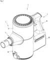
- FIG. 1 is a perspective view of a cleaner according to an embodiment of the present invention
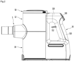
- FIG. 2 is a side view of the cleaner according to an embodiment of the present invention
- FIG. 3 is a plan view of the cleaner according to an embodiment of the present invention
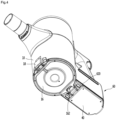
- FIG. 4 is a perspective view of the cleaner according to an embodiment of the present invention when seen from under the cleaner
- FIG. 5 is a cross-sectional view of the cleaner according to an embodiment of the present invention.
- a cleaner 1 may include a main body 2.
- the cleaner 1 may further include a suction unit 5 coupled to the front of the main body 2.
- the suction unit 5 can guide air containing dust into the main body 2.
- the cleaner 1 may further include a handle unit 3 coupled to the main body 2.
- the handle unit 3 may be positioned opposite to the suction unit 5 on the main body 2.
- the main body 2 may be disposed between the suction unit 5 and the handle unit 3.
- the main body 2 may include a first body 10 and a second body 12 on the first body 10.
- the first body 10 and the second body 12 may be directly combined or may be indirectly combined through an intermediate member.
- the first body 10 and the second body 12 may be, though not limited thereto, formed in a cylindrical shape.
- the first body 10 and the second body 12 are open at the top and the bottom, respectively. That is, the bodies 10 and 12 may have a top opening and a bottom opening, respectively.
- the suction unit 5 may be coupled to the main body 2 such that the center of the suction unit 5 is positioned approximately at the boundary between the first body 10 and the second body 12.
- the main body 2 may further include a dust separation unit that separates dust from air sucked through the suction unit 5.
- the dust separation unit may include a first cyclone unit 180 that can separate dust, for example, using cyclonic flow.
- the first body 10 includes the first cyclone unit 180 in this configuration.
- the air and dust sucked through the suction unit 5 helically flow along the inner side of the first cyclone unit 180.
- the axis of the cyclonic flow in the first cyclone unit 110 may vertically extend.
- the dust separation unit may further include a second cyclone unit 130 that secondarily separates dust from the air discharged out of the first cyclone unit 110.
- the second cyclone unit 130 may be disposed inside the first cyclone unit 110 to minimize the size of the dust separation unit.
- the second cyclone unit 130 may include a plurality of cyclone bodies arranged in a raw.
- the dust separation unit may include one cyclone unit, in which the axis of the cyclonic flow may also vertically extend.
- the first body 10 functions as a dust container that stores dust separated by the cyclone units 110 and 130.
- the main body 2 may further include a body cover 16 for opening/closing the bottom of the first body 10.
- the body cover 16 can open/close the first body 10 by being rotated.
- a button 18 for rotating the body cover 16 may be disposed on the first body 10.
- a hinge 162 of the body cover 16 may be coupled to hinge coupling portions 620 of the battery housing 60.
- At least a portion of the second cyclone unit 130 may be positioned inside the first body 10.
- a dust storage guide 124 that guides the dust separated by the second cyclone unit 130 to be stored may be disposed in the first body 10.
- the dust storage guide 124 may be coupled to the bottom of the second cyclone unit 130 in contact with the top of the body cover 16.
- the dust storage guide 124 may divide the internal space of the first body 10 into a first dust storage part 121 where the dust separated by the first cyclone unit 110 is stored and a second dust storage part 123 where the dust separated by the second cyclone unit 130 is stored.
- the internal space of the dust storage guide 124 is the second dust storage part 123 and the space between the dust storage guide 124 and the first body 10 is the first dust storage part 121.
- the body cover 16 can open/close both of the first dust storage part 121 and the second dust storage part 123.
- the cleaner 1 may further include a suction motor 20 for generating suction force and a battery 40 for supplying power to the suction motor 20.
- the suction motor 20 may be disposed in the second body 12. At least a portion of the suction motor 20 may be disposed over the dust separation unit. Accordingly, the suction motor 20 is disposed over the first body 10.
- the suction motor 20 may communicate with an outlet of the second cyclone unit 130.
- the main body 2 may further include a discharge guide 28 connected to the second cyclone unit 130 and a flow guide 22 that communicates with the discharge guide 28.
- the discharge guide 28 is disposed on the second cyclone unit 130 and the flow guide 22 is disposed over the discharge guide 28.
- suction motor 20 is positioned inside the flow guide 22.
- the axis of the cyclonic flow in the first cyclone unit 110 may pass through the suction motor 20.
- the suction motor 20 When the suction motor 20 is disposed over the second cyclone unit 130, the air discharged from the second cyclone unit 130 can flow directly to the suction motor 20, so the channel between the dust separation unit and the suction motor 20 can be minimized.
- the suction motor 20 may include a rotary impeller 200.
- the impeller 200 may be fitted on a shaft 202.
- the shaft 202 is vertically disposed.
- An extension line from the shaft 202 (which may be considered as the rotational axis of the impeller 200) may pass through the first body 10.
- the rotational axis of the impeller 200 and the axis of the cyclonic flow in the first cyclone unit 180 may be on the same line.
- the path through which the air discharged from the dust separation unit, that is, the air discharged upward from the second cyclone unit 190 flows to the suction motor 20 can be reduced and a change in direction of air can be decreased, so a loss of airflow can be reduced.
- suction force can be increased and the lifetime of the battery 40 for supplying power to the suction motor 20 can be increased.
- the cleaner 1 may further include an upper motor housing 26 covering a portion of the top of the suction motor 20 and a lower motor housing 27 covering a portion of the bottom of the suction motor 20.
- the suction motor 20 may be disposed inside the motor housings 26 and 27 and the flow guide 22 may be disposed to cover the upper motor housing 26.
- At least a portion of the flow guide 22 may be spaced apart from the upper motor housing 26. Further, at least a portion of the flow guide 22 may be spaced apart from the second body 12.
- a first air passage 232 is defined by the inner side of the flow guide 22 and the outer side of the upper motor housing 26 and a second air passage 234 is defined by the outer side of the flow guide 22 and the inner side of the second body 12.
- the air discharged from the second cyclone unit 190 flows to the suction motor 20 through the first air passage 232 and the air discharged from the suction motor 20 flows through the second air passage 234 and is then discharged outside. Accordingly, the second air passage 234 functions as an exhaust channel.
- the handle unit 3 may include a handle 30 for a user to hold and a battery housing 60 under the handle 30.
- the handle 30 may be disposed behind the suction motor 20.
- the direction in which the suction unit 5 is positioned is the front direction and the direction in which the handle 30 is positioned is the rear direction.
- the battery 40 may be disposed behind the first body 10. Accordingly, the suction motor 20 and the battery 40 may be arranged not to vertically overlap each other and may be disposed at different heights.
- the suction motor 20 that is heavy is disposed ahead of the handle 30 and the battery 40 that is heavy is disposed behind the handle 30, so weight can be uniformly distributed throughout the cleaner 1. It is possible to prevent injuries to the user's wrist when a user cleans with the handle 30 in his/her hand. That is, since the heavy components are distributed at the front and rear portions and at different heights in the cleaner 1, it is possible to prevent the center of gravity of the cleaner 1 from concentrating on any one side.
- the battery 40 is disposed under the handle 30 and the suction motor 20 is disposed in front of the handle 30, there is no component over the handle 30. That is, the top of the handle 30 forms a portion of the external appearance of the top of the cleaner 1.
- the handle 30 may include a first extension 310 extending vertically to be held by a user and a second extension 320 extending toward the suction motor 20 over the first extension 310.
- the second extension 320 may at least partially horizontally extend.
- the first extension 310 which is a portion that a user can hold (a portion that a user's palm can come in contact with), may be referred to as a grip part.
- a stopper 312 for preventing a user's hand holding the first extension 310 from moving in the longitudinal direction of the first extension 310 (vertically in FIG. 2 ) may be formed on the first extension 310.
- the stopper 312 may extend toward the suction unit 5 from the first extension 310.
- the stopper 312 is spaced apart from the second extension 320. Accordingly, a user is supposed to hold the first extension 310, with some of the fingers over the stopper 312 and the other fingers under the stopper 312.
- the stopper 312 may be positioned between the index finger and the middle finger.
- the longitudinal axis A1 of the suction unit 5 may pass through the user's wrist.
- the longitudinal axis A1 of the suction unit 5 When the longitudinal axis A1 of the suction unit 5 passes through the user's wrist and the user's arm is stretched, the longitudinal axis A1 of the suction unit 5 may be substantially aligned with the user's stretched arm. Accordingly, there is the advantage in this state that the user uses minimum force when pushing or pulling the cleaner 1 with the handle 30 in his/her hand.
- the handle 30 may include an operation unit 326.
- the operation unit 326 may be disposed on an inclined surface of the second extension 320. It is possible to input instructions to turn on/off the cleaner (suction motor) through the operation unit 326. For example, it is possible to input instructions to turn on/off the suction motor through the operation unit 326. Further, it is possible to control the intensity of the suction force of the suction motor 20 that has been turned on through the operation unit 326.
- the operation unit 326 may be disposed to face a user.
- the operation unit 326 may be disposed opposite to the stopper 312 with the handle 30 therebetween.
- the operation unit 326 is positioned higher than the stopper 312. Accordingly, a user can easily operate the operation unit 326 with his/her thumb with the first extension 310 in his/her hand.
- the operation unit 326 is positioned outside the first extension 310, it is possible to prevent the operation unit 326 from being unexpectedly operated when a user cleans with the first extension 310 in his/her hand.
- a display unit 322 for showing operational states may be disposed on the second extension 320.
- the display unit 322 may be, for example, disposed on the top of the second extension 320. Accordingly, a user can easily check the display unit 322 on the top of the second extension 320 while cleaning.
- the display 322, for example, can show the remaining capacity of the battery 40 and the intensity of the suction motor.
- the display unit 322 may include a plurality of light emitting devices.
- the light emitting devices may be spaced apart from each other in the longitudinal direction of the second extension 320.
- the battery housing 60 may be disposed under the first extension 310.
- the battery 40 may be detachably combined with the battery housing 60.
- the battery 40 may be inserted into the battery housing 60 from under the battery housing 60.
- the rear side of the battery housing 60 and the rear side of the first extension 310 may form a continuous surface. Accordingly, the battery housing 60 and the first extension 310 can be shown like a single unit.
- the bottom of the battery 40 may be exposed to the outside. Accordingly, when the cleaner 1 is placed on the floor, the battery 40 can be in contact with the floor.
- the bottom of the battery 40 since the bottom of the battery 40 is exposed to the outside, the bottom of the battery 40 can come in direct contact with the air outside the cleaner 1, so the battery 40 can be more efficiently cooled.
- the cleaner 1 may further include a filter unit 50 having air exits 522 for discharging the air that has passed through the suction motor 20.
- the air exits 522 may include a plurality of openings and the openings may be circumferentially arranged. Accordingly, the air exist 522 may be arranged in a ring shape.
- the filter unit 50 may be detachably coupled to the top of the main body 2.
- the filter unit 50 may be detachably inserted in the second body 12.
- the filter unit 50 When the filter unit 50 is combined with the main body 2, a portion of the filter unit 50 is positioned outside the second body 12. Accordingly, a portion of the filter unit 50 is inserted in the main body 2 through the open top of the main body 2 and the other portion protrudes outside from the main body 2.
- the height of the main body 2 may be substantially the same as the height of the handle 30. Accordingly, the filter unit 50 protrudes upward from the main body 2, so a user can easily hold and separate the filter unit 50.
- the air exits 522 are positioned at the upper portion of the filter unit 50. Accordingly, the air discharged from the suction motor 20 is discharged upward from the main body 2.
- the main body 2 may further include a pre-filter 29 for filtering the air flowing into the suction motor 20.
- the pre-filter 29 may be disposed inside the flow guide 22. Further, the pre-filter 29 is seated over the upper motor housing 16 and may surround a portion of the upper motor housing 26. That is, the upper motor housing 26 may include a filter support for supporting the pre-filter 29.
- FIG. 6 is a view when a battery according to an embodiment of the present invention has been separated from a battery housing
- FIG. 7 is a view when an inner housing according to an embodiment of the present invention has been separated from the battery housing
- FIG. 8 is a view after the inner housing shown in FIG. 7 is coupled to the battery housing.
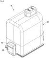
- FIG. 9 is a perspective view of the battery according to an embodiment of the present invention and FIG. 10 is a front view of the battery shown in FIG. 9 .
- the battery housing 60 may include an outer housing 600 that is integrally formed with the handle 30 and an inner housing 610 that can be inserted in the outer housing 600.
- the inner housing 610 may be inserted a lower side of the outer housing 600.
- the inner housing 610 provides a battery chamber 611 for receiving the battery 40.
- the inner housing 610 may be fixed to one or more of the outer housing 600 and the first body 10. Further, the battery 40 may be coupled to the inner housing 610.
- the inner housing 610 is inserted into the outer housing 600 and then the battery 40 is inserted to be coupled to the inner housing 610, so it is possible to prevent the outer housing 600 from deforming or to prevent the outer housing 600 from being damaged when inserting or separating the battery 40.
- the inner housing 610 may have a pair of hinge coupling portions 620 to which a hinge 162 of the body cover 16 is coupled.
- the hinge coupling portions 620 may be spaced at a predetermined distance from each other. Accordingly, a space 622 may be formed between the hinge coupling portions 620.
- the inner housing 610 may further include a body fastening portion 642 to be fastened to the first body 10.
- the inner housing 610 may further include first main body terminals 630 for charging the battery 40 coupled to the inner housing 610. It is possible to bring charging stand terminals in contact with the first main body terminals 630 by placing the cleaner 1 on a charging stand (not shown).
- the first main body terminals 630 are disposed on the bottoms of the hinge coupling portions 620, but can be spaced apart from the floor when the cleaner 1 is placed on the floor. That is, terminal grooves 623 that are concave upward are formed on the bottoms of the hinge coupling portions 620 and the first main body terminals 630 can be disposed in the terminal grooves 623. Accordingly, damage to the first main body terminals 630 can be prevented.
- first main body terminals 630 are disposed in the terminal grooves 623, water cannot come in contact with the first main body terminals 630 when the cleaner 1 is placed on a floor.
- the battery 40 may include a frame 410 that forms the external shape.
- the frame 410 and the battery chamber 611 may be formed in shapes corresponding to each other.
- the battery 40 may further include a plurality of coupling portions 470 and 474.
- the coupling portions 470 and 474 may include a first coupling portion 470 disposed on a first side of the frame 410 and a second coupling portion 474 disposed on a second side of the frame 410.
- the first coupling portion 470 and the second coupling portion 474 may be positioned opposite to each other.
- the first coupling portion 470 may include a first hook 472.
- the first coupling portion 470 may be movably coupled to the outer side of the frame 410.
- the first coupling portion 470 can be elastically supported by an elastic member 473 (see FIG. 23 ) in the frame 410.
- a locking rib 640 for locking the first hook 472 of the first coupling portion 470 may be formed between the hinge coupling portions 620.
- the first hook 472 of the first coupling portion 470 can be locked to the locking rib 640 through the space 622.
- the second coupling portion 474 is integrally formed with the frame 410 and can be elastically deformed by external force.
- an extension 475 horizontally extends from the bottom of the frame 410 and the second coupling portion 474 extends upward from the end of the extension 475.
- the second coupling portion 474 is spaced from the outer side of the frame 410 by the extension 475.
- a space for deformation is defined between the frame 410 and the second coupling portion 474.
- the second coupling portion 474 can be elastically deformed toward the fame 410 by the space.
- the second coupling portion 474 may include a second hook 476.
- the second hook 476 may be thinner than other portion of the second coupling portion 474.
- the outer housing 600 has a first exposing hole 602 and the inner housing 610 has a second exposing hole 612 to expose the second coupling portion 474 to the outside so that the second coupling portion 474 can be operated with the battery 40 in the battery chamber 611.
- a coupling slot 614 for coupling the second hook 476 of the second coupling portion 474 may be formed over the second exposing hole 612 of the inner housing 610.
- the coupling slot 614 may be a hole or a groove.
- the second hook 476 of the second coupling portion 474 can be inserted into the locking slot 614 when being inserted in the inner housing 610.
- FIG. 11 is an exploded perspective view of the battery according to an embodiment of the present invention
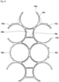
- FIG. 12 is a perspective view showing a battery holder of the present invention
- FIG. 13 is a plan view of the battery holder shown in FIG. 12 .
- the battery 40 may further include a plurality of battery cells 430, a battery holder 440 supporting the battery cells 430, a battery management unit 480 managing the voltage of the battery cells 430, and battery terminals 490 connected to the battery management unit 480.
- the battery cells 430, the battery holder 440, and the battery management unit 480 may be covered by the frame 410.
- the battery 40 may further include a barrier 450 disposed between the battery cells 430 and the battery management unit 480.
- the barrier 450 blocks heat transferring from the battery cells 430 to the battery management unit 480.
- the frame 410 may include a first frame 420 and a second frame 460 coupled to the lower portion of the first frame 420.
- a protrusion 422 is formed on the top of the first frame 420 and terminal holes 424 through which second main body terminals 670 (see FIG. 23 ) to be described below pass may be formed in the protrusion 422.
- the terminal holes 424 are formed through the top of the protrusion 422. Accordingly, while the battery 40 is inserted upward into the battery hosing 60, the second main body terminals 670 (see FIG. 23 ) can be connected to the battery terminals 490 through the terminal holes 424.
- the protrusion 422 may be positioned at a side from the center of the first frame 420 so that a user can easily recognize the direction in which the battery 40 is inserted into the battery housing 60.
- the protrusion 422 may be positioned closer to the second coupling portion 474 between the first coupling portion 470 and the second coupling portion 474.
- a seat 461 in which the lower end of the first frame 410 is seated may be formed at the top of the second frame 460.
- the battery management unit 480 may be coupled to the top of the barrier 450.
- the battery management unit 480 may include one or more fastening holes 482 to be fastened to the barrier 450 by fasteners.
- the battery holder 440 allows the battery cells 430 to be arranged in erected positions.
- the longitudinal direction of the battery cells 430 may be in parallel with the directions in which the battery 40 is inserted into and separated from the battery housing 60.
- the battery holder 440 allows the battery cells 430 to be arranged in a plurality of rows.
- the battery cells 430 may include seven battery cells and the battery holder 440 may allow some of the seven battery cells to be arranged in two rows.
- the number of the battery cells 430 is not limited.
- the battery holder 440 may have a separation wall 441 for dividing the battery cells 430 in two separate rows, first holders 422 formed at the upper portion of the separation wall 441, and second holders 445 formed at the lower portion of the separation wall 441.
- the first holders 442 surround the upper portions of the battery cells 430 and the second holder 445 surround the lower portions of the battery cells 430.
- the first holders 442 and the second holders 445 are vertically spaced from each other.
- heat generated by the battery cells 430 in the two rows can be prevented from influencing each other in other rows by the separation wall 441.
- the structure and shape of the second holders 445 are the same as those of the first holders 442, so hereafter, only the first holders 442 are described in detail and the description of the first holders 442 is referred to for the structure and shape of the second holders 445.
- the first holders 442 may include cell cases 442a, 442b, 443a, 443b, and 443c that surround the upper portions of the battery cells 430.
- the battery cells 430 are spaced from each other with the upper portions surrounded by the cell cases 442a, 442b, 443a, 443b, and 443c.
- the cell cases 442a, 442b, 443a, 443b, and 443c may include first cell cases 442a and 442b that surround the entire outer sides of some of the battery cells 430, second cell cases 443a and 443b that partially surround the outer sides of some of the battery cells 430, and a third cell case 443c disposed between the two cell cases 443a and 443b.
- first cell cases 442a and 442b may be formed in a cylindrical shape
- second cell cases 443a and 443b and the third cell case 443c may be formed in a C-shape having an opening 443d.
- first cell cases 442a and 442b are in contact with each other, in which any one first cell case 442a surrounds a battery cell 430 in the first row and the other first cell case 442b surround a battery cell 430 in the second row.
- two second cell cases 443a and 443b may be horizontally spaced from each other with the separation wall 441 therebetween and may be connected to connectors 444a and 444b.
- the connectors 444a and 444b may include a first connector 444a vertically connecting the two second cell cases 443a and 443b and a second connector 444b horizontally extending and connecting the two second cell cases 443a and 443b.
- the second connector 444b may be in contact with the upper portion of the separation wall 441.
- the distance between the centers of the two second cell cases 443a and 443b is longer than the distance between the centers of the two first cell cases 442a and 442b.
- the first cell cases 442a and 442b may be disposed between two groups of second cell cases 443a and 443b.
- a second cell case, a first cell case, and a second cell case may be sequentially arranged.
- the battery cells 430 can be arranged in a zigzag pattern in each row, so the horizontal length of the battery 40 can be reduced.
- the battery cells 430 are arranged in a zigzag pattern, even if the number of the battery cells 430 is increased, the size of the battery 40 is not increased not that much, so the maximum chargeable voltage of the battery 40 can be increased.
- the third cell case 443c is disposed between two spaced second cell cases 443a and 443b. Therefore, according to the present invention, the horizontal length of the battery 40 can be reduced.
- FIG. 14 is a plan view of a second frame according to an embodiment of the present invention and FIG. 15 is a plan view after the battery holder and the battery cells are seated inside the second frame.
- the second frame 460 may have a support flange 462 for supporting the lower ends of the inner housing 610 and the outer housing 600 with the battery 40 inserted in the battery housing 60.
- the support flange 462 may horizontally extend outward from the bottom of the second frame 460.
- a coupling body 479 for coupling the first coupling portion 470 is formed on one side around the second frame 460 and the second coupling portion 474 is formed on another side around the second frame 460.
- the second frame 460 may further include contact ribs 463, 464, and 465 being in contact with the battery cells 430 retained in the battery holder 440.
- the contact ribs 463, 464, and 465 prevent horizontal movement of the battery cells 430 in the frame 410 in contact with the battery cells 430.
- the contact ribs 463, 464, and 465 may include first contact ribs 463 disposed at corners of the second frame 460, second contact ribs 464 being in contact with the battery cells 430 in the second cell cases 443a and 443b disposed between the first cell cases 442a and 442b and the third cell case 443c, and a third contact rib 465 being in contact with the battery cell 430 in the third cell case 443c.
- the second cell cases 443a and 443b and the third cell case 443c have the openings 443d, when the battery cells 430 are fitted in the second cell cases 443a and 443b and the third cell case 443c, the battery cells 430 are partially exposed to the outside, and accordingly, the contact ribs 463, 464, and 465 can come in contact with the battery cells 430.
- the contact ribs 463, 464, and 465 may be rounded with a curvature corresponding to the curvature of the outer sides of the battery cells 430 to stably in contact with the battery cells 430.
- the space between the battery holder 440 and the second frame 460 functions as a heat dissipation space for heat from the battery cells 430 to be naturally dissipated.
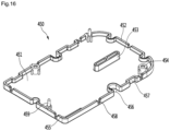
- FIG. 16 is a perspective view of the barrier according to an embodiment of the present invention
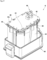
- FIG. 17 is a perspective view showing the battery shown in FIG. 9 with a first frame removed
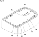
- FIG. 18 is a horizontal cross-sectional view of the battery which shows the arrangement relationship between stop ribs of the first frame and a battery management unit
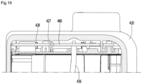
- FIG. 19 is a vertical cross-sectional view of the battery which shows the arrangement relationship between the stop ribs of the first frame and the battery management unit.
- the barrier 450 may include a flat plate 451.
- the plate 451 is disposed over the battery cell 430 to block heat transferring from the battery cell 430 to the battery management unit 480.
- the barrier 450 may further include an outer rib 452 protruding upward along the edge of the plate 451.
- the outer rib 452 increases the strength of the barrier 450.
- the battery management unit 480 may include a circuit board 481 and the battery terminals 490 may be directly formed on the circuit board 481. Pin holes 483 through which terminal connection pins to be described below pass may be formed at the battery management unit 480.
- the circuit board 481 may be coupled to the barrier 450 over the plate 451.
- the circuit board 481 and the plate 451 are arranged in parallel and spaced from each other.
- the longitudinal direction of the battery cell 430 may cross the circuit board 481 and the plate 451.
- the second main body terminals 670 While the battery 40 is inserted into the battery housing 60, the second main body terminals 670 (see FIG. 23 ) are coupled to the battery terminals 490.
- a downward force may be applied to the battery terminals 490.
- the pressure applied to the battery terminals 490 may be transmitted to the circuit board 481 and the circuit board 481 is spaced apart from the plate 451, so when the circuit board 481 is pressed down, the circuit board 481 can be deformed, and in this case, the circuit board 481 may be broken.
- the barrier 450 may further include an anti-deformation rib 453 extending toward the circuit board 481 from the plate 451 and preventing deformation of the battery management unit 480 in order to prevent breakage of the circuit board 481.
- the anti-deformation rib 453 may be in contact with the circuit board 481, adjacent to the pin holes 483 of the circuit board 481.
- the anti-deformation rib 453 may be in contact with the circuit board 481.
- the anti-deformation rib 453 may be disposed close to the circuit board 481, and it may be brought in contact with the bottom of the circuit board 481 when the circuit board 481 is pressed down.
- the anti-deformation rib 453 may be spaced apart from the circuit board 451 when the second main body terminals 670 (see FIG. 23 ) is separated from the battery terminals, and it may be in contact with the circuit board 481 when the second main body terminals 670 (see FIG. 23 ) are coupled to the battery terminals 490.
- the barrier 450 may further include one or more fastening bosses 454 to be fastened to the circuit board 481 by fasteners.
- the fastening bosses 454 may extend upward on the plate 451.
- the fastening bosses 454 may be positioned inside the outer rib 452 and may be formed integrally with the outer rib 452.
- the fastening bosses 454 protrude higher than the outer rib 452 from the plate 451 so that the outer rib 452 and the circuit board 481 can be spaced from each other when the barrier 450 and the circuit board 481 are fastened.
- the plate 451 may include a guide hole 455 through which a first top conductive plate 433 passes and guide grooves 457 for guiding second top conductive plates 433a.
- the guide hole and grooves 455 and 457 guide the top conductive plates 433 and 433a to the circuit board 481, so they may be referred to as, in combination, a first guide.
- the circuit board 481 may also include a guide hole 485 (or it may be referred to as a second guide) through which the first conductive plate 433 passes.
- the anodes (+) and the cathodes (-) of two adjacent battery cells of the battery cells 430 may be connected through a conductor.
- the conductive plates 433 and 433a may be connected to the conductor connecting the two battery cells 430.
- three conductors may connect the anodes (+) and the cathodes (-) of two battery cells and one conductor may be connected to one electrode (anode (+) or cathode (-)) of one battery cell, over the battery cells.
- the first top conductive plate 433 may be connected to the top of the circuit board 481 through the guide holes 485 of the plate 451 and the circuit board 481.
- the second top conductive plates 433a may be guided upward along the guide grooves 457 and then bent horizontally, whereby they can be connected to the top of the circuit board 481.
- the battery management unit 480 can manage the voltage of the battery cells 430.
- the plate 451 may include guide projections 459 for guiding the circuit board 481 when it is combined with the circuit board 481.
- the guide projection 459 may protrude upward from the plate 451.
- the guide projections 459 may protrude higher than the outer rib 452 to be able to pass through the circuit board 481.
- Projection holes 489 through which the guide projections 459 pass may be formed at the circuit board 481.
- the first frame 420 may include a plurality of stop ribs for preventing moment of the barrier and the battery management unit 480 inside the first frame 420.
- the stop ribs may protrude from the inner side of the first frame 420.
- the stop ribs may include a first stop rib 427 and a second stop rib 428.
- the circuit board 481 may include a rib slot 488 through which the first stop rib 427 passes and the barrier 450 may include a rib seat 458 in which the first stop rib 427 passing through the rib slot 488 is seated.
- the first stop rib 427 When the first stop rib 427 is seated in the rib seat 458, the first stop rib 427 may be seated on the plate 451.
- the second stop rib 428 may be seated on the outer rib 452.
- FIG. 20 is a view showing the battery shown in FIG. 9 with the second frame removed.
- a plurality of first bottom conductors 437 may connect the anodes (+) and the cathodes (-) of two battery cells 430 under the battery cells 430.
- three first bottom conductors 437 may connect the anodes (+) and the cathodes (-) of two battery cells and one second bottom conductor 437a may be connected to one electrode (anode (+) or cathode (-)) of one battery cell, under the battery cells.
- First bottom conductive plates 438 may be connected to the first bottom conductors 437.
- the first bottom conductive plats 438 may be integrally formed with the first bottom conductors 437 and may be bent upward from the first bottom conductors 437.
- Second bottom conductive plates 438a may be connected to the second bottom conductors 437a.
- the second bottom conductive plats 438a may be integrally formed with the second bottom conductors 437a and may be bent upward from the second bottom conductors 437a.
- Wires 436 may be connected to the bottom conducive plates 438 and 438a.
- the wires 436 may be connected to the circuit board 481.
- the barrier 450 may include wire seats 456 in which the wires 436 are seated and the circuit board 481 may include wire holes 486 through which the wires 436 pass.
- the wire grooves 456 may be referred to as first wire guides and the wire holes 486 may be referred to as second wire guide.
- FIG. 21 is a perspective view showing the battery terminals according to an embodiment of the present invention and FIG. 22 is a front view of a battery terminal of the present invention.
- a pair of battery terminals 490 may be directly disposed on the circuit board 481.
- the battery terminals 490 may be erected on the circuit board 481.
- the battery terminals 490 may be partially or fully disposed in the protrusion 422 of the frame 410.
- the second main body terminals 670 can be coupled to the battery terminals 490.
- the battery terminals 490 each may have a base 491 to be installed on the circuit board 481.
- the base 491 may include a plurality of installation pins 491a, 491b, and 491c passing through the pin holes 483 of the circuit board 481.
- the installation pins 491a, 491b, and 491c may include a first pin 491a and a second pin 491b spaced from each other.
- the first pin 491a and the second pin 491b may be arranged to face each other.
- the installation pins 491a, 491b, and 491c may include a third pin 491c disposed to cross the first pin 491a and the second pin 491b in an area corresponding to the area between the first pin 491a and the second pin 491b.
- the anti-deformation rib 453 of the barrier 450 may be positioned in an area between a line connecting the first pin 491a and the second pin 491b, and the third pin 491c
- the battery terminals 490 each may have a pair of clip terminals 492 and 493 extending upward from the base 491.
- the clip terminals 492 and 493 may include a first clip terminal 492 and a second clip terminal 493.
- the first clip terminal 492 and the second clip terminal 493 can be elastically deformed on the base 491 and the second main body terminal 670 (see FIG. 23 ) are in contact with the first clip terminal 492 and the second clip terminal 493 between the first clip terminal 492 and the second clip terminal 493.
- the clip terminals 492 and 493 may extend toward each other, as they go upward, and then extend away from each other at a predetermined height.
- the clip terminals 492 and 493 may have contact portions 497a and 497b, respectively. That is, the first clip terminal 492 may have a first contact portion 497a and the second clip terminal 493 may have a second contact portion 497b.
- a cut portion 494a and 494b for dividing the clip terminals 492 and 493 into a plurality of independent terminals, respectively, may be formed at the clip terminals 492 and 493.
- the number of independent terminals of the clip terminals 492 and 493 is increased, so the reliability in contact with the second main body terminal 670 (see FIG. 23 ) is improved, but the contact area with the second main body terminal 670 (see FIG. 23 ) is decreased, so a short circuit may occur when a current is high.
- the clip terminals 492 and 493 each have two independent terminals 495a, 495b, 496a, and 496b horizontally spaced from each other by the cut portions 494a and 494b, respectively.
- the first clip terminal 492 includes a first independent terminal 495a and a second independent terminal 495b and the second clip terminal 403 includes a third independent terminal 496a and a fourth independent terminal 496b.
- the independent terminals 495a, 495b, 496a, and 496b have contact portions 497a and 497b, respectively. Accordingly, the clip terminals each have two contact portions 497a and 497b in the present invention.
- the first contact portion 497a of the first clip terminal 492 and the second contact portion 497b of the second clip terminal 493 may be spaced from each other in parallel with the coupling direction of the second main body terminal 670 (see FIG. 23 ).
- first contact portion 497a and the second contact portion 497b may be arranged not to face each other.
- first contact portion 497a and the second contact portion 497b may be vertically spaced from each other.
- the horizontal gap between the first contact portion 497a and the second contact portion 497b is smaller than the thickness of the second main body terminal 670 (see FIG. 23 ) and the gap may not be provided.
- a virtual line connecting the first contact portion 497a and the second contact portion 497b is a vertical line.
- first contact portion 497a and the second contact portion 497b may be arranged to vertically overlap each other.
- the gap between the first contact portion 497a and the second contact portion 497b can be kept smaller than the thickness of the second main body terminal 670 (see FIG. 23 ), so the contact reliability can be improved.
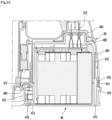
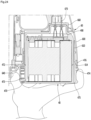
- FIG. 23 is a cross-sectional view showing the battery inserted in the battery housing and FIG. 24 is a view when a user has operated a first coupling portion and a second coupling portion to separate the battery from the battery housing.
- the battery housing 60 may have the receiving portion 660 for receiving the protrusion 422.
- the receiving portion 660 may have second main body terminals 670 for coupling to the battery terminals 490.
- the receiving portion 670 guides the protrusion 424 moving upward so that the second main body terminals 670 can be stably inserted through the terminal holes 422.
- a user can insert fingers into the space 622 defined between the hinge coupling portions 620.
- the user can press the first coupling portion 470 toward the frame 410 with the finger. Accordingly, the elastic member 473 contracts and the first hook 472 of the first coupling portion 470 is unlocked from the locking rib 640.
- the user can unlock the second coupling portion 474 from the battery housing 60 by operating the second coupling portion 474 exposed to the outside of the battery housing 60.
- the user presses the second coupling portion 474 toward the frame 410. Accordingly, the second coupling portion 474 is bent toward the frame 410 by the space between the frame 410 and the second coupling portion 474. Therefore, the second hook 476 is pulled out of the coupling slot 614.
- first coupling portion 470 and the second coupling portion 474 are moved toward each other by a user, whereby they are unlocked.
- a user can unlock the first coupling portion 470 and the second coupling portion 474 using two fingers, so the user can easily separate the battery 40 downward from the battery housing 60.
- the battery 40 can be separated from the battery housing 60, it is possible to place only the battery 40 on the cradle to charge it.
- FIG. 25 is a perspective view of battery terminals according to another embodiment of the present invention.
- the battery terminals of this embodiment are the same as those shown in FIG. 21 , except for the positions of the contact portions of the independent terminals. Accordingly, only characteristic parts of this embodiment are described hereafter.
- the battery terminals of this embodiment each may have a base 490a and a first clip terminal and a second clip terminal that extend from the base 490a.
- the first clip terminal may have a first independent terminal 701 and a second independent terminal 702 and the second clip terminal may have a third independent terminal 703 and a fourth independent terminal 704.
- the first independent terminal 701 and the second independent terminal 702 are spaced from each other in a second direction (in the direction of an arrow A) that crosses a first direction in which the battery 40 is inserted into the battery housing 60.
- the third independent terminal 703 and the fourth independent terminal 704 are spaced from each other in the second direction.
- the first independent terminal 701 may have a first contact portion 701a and the second independent terminal 702 may have a second contact portion 702a positioned at the same height as the first contact portion 701a.
- the third independent terminal 703 may have a third contact portion 703a positioned at a different height from the first contact portion 701a and the fourth independent terminal 704 may have a fourth contact portion 704a positioned at the same height as the third contact portion 703a.
- the second contact portion 702a may be positioned in an area corresponding to the area between the first contact portion 701a and the third contact portion 703a.
- the third contact portion 703a may be positioned in an area corresponding to the area between the second contact portion 702a and the fourth contact portion 704a.
- the horizontal distance between the first contact portion 710a and the fourth contact portion 704a is set smaller than the thickness of the second main body terminal 670.
- first contact portion 701a and the second contact portion 702a may be spaced from each other in a third direction (the direction of an arrow B) that is the arrangement direction of the first clip terminal and the second clip terminal. Further, the third contact portion 703a and the fourth contact portion 704a may be spaced from each other in the third direction.
- the third direction crosses the first direction and the second direction.
- the deformation amount of the second contact portion 702a and the third contact portion 703a is large in the early stage of use after the cleaner is purchased. Further, even if the deformation amount of the second contact portion 702a and the third contact portion 703a is large and the restoring force is reduced, the first contact portion 701a and the fourth contact portion 704a can be stably brought in contact with the second main body terminal.
- FIG. 26 is a view showing a battery according to another embodiment of the present invention inserted in a battery housing and FIG. 27 is a view when the battery is separated from the battery housing in the state shown in FIG. 26 .
- This embodiment is the same as the previous embodiment except the structure and method for mounting and separating the battery. Accordingly, only characteristic parts of this embodiment are described hereafter.
- the battery 40 may further have a plurality of coupling portions 470a and 474.
- the coupling portions 470a and 474 may include a first coupling portion 470a disposed on a first side of the frame 410 and a second coupling portion 474 disposed on a second side of the frame 410.
- the first coupling portion 470a and the second coupling portion 474 may be positioned opposite to each other.
- the second coupling portion 474 of this embodiment is the same as that of the first embodiment, so it is not described in detail.
- the first coupling portion 470a unlike the first coupling portion 470 of the first embodiment, is not movably disposed on the frame 410 of the battery 40, but may be fixed to the frame 410. Alternatively, the first coupling portion 470a may be formed integrally with the frame 410. The first coupling portion 470a may have a first hook 472a.
- the first hook 472a of the first coupling portion 470a may be locked to the locking rib 640.
- the first hook 472a and the locking rib 640 may be unlocked from each other.
- the first hook 472a is unlocked from the locking rib 640, so the battery 40 can be separated from the battery housing 600.
- the battery terminals 490 should be separated from the second main body terminal 670.
- one or more of the battery terminals 490 and the second main body terminal 670 should be elastically deformed.
- the battery terminals 490 each have a plurality of clip terminals, as described above with reference to the first embodiment, in order to easily elastically deform the battery terminals 490.
- the second main body terminals 670 vertically extend and the clip terminals are horizontally arranged.
- the second main body terminals 670 each have a plurality of terminal pins 671 and 672.
- the terminal pins 671 and 672 are horizontally spaced from each other.
- the terminal pins 671 and 672 have a width larger than the thickness.
- the terminal pins 671 and 672 respectively have contact surfaces 671a, 671b, 672a, and 672b that are in contact with the clip terminals, respectively.
- a second contact surface 672b of the first terminal pin 671 and a first contact surface 672a of the second terminal pin 671 are arranged to face each other. According to this arrangement, when a force perpendicular to the contact surfaces 671a, 671b, 672a, and 672b is applied to the terminal pins, the terminal pins can be elastically deformed.
- the clip terminals are horizontally arranged, the clip terminals can be elastically deformed when the battery 40 is separated.
- the battery terminals 490 and the second main body terminals 670 can be elastically deformed, and as a result, the second main body terminals 670 can be pulled out of a pair of clip terminals of each of the battery terminals 490. Deformation of the clip terminals is exemplified in FIG. 27 .
- the method of coupling the battery 40 to the battery housing 600 is the opposite to the method of separating the battery 40 from the battery housing 600, so it is not described in detail.
Landscapes
- Engineering & Computer Science (AREA)
- Chemical & Material Sciences (AREA)
- Chemical Kinetics & Catalysis (AREA)
- Electrochemistry (AREA)
- General Chemical & Material Sciences (AREA)
- Mechanical Engineering (AREA)
- Manufacturing & Machinery (AREA)
- Microelectronics & Electronic Packaging (AREA)
- Battery Mounting, Suspending (AREA)
- Extrusion Moulding Of Plastics Or The Like (AREA)
- Electric Vacuum Cleaner (AREA)
Claims (13)
- Reiniger, der aufweist:ein Batteriegehäuse (60);einen Hauptkörperanschluss (670), der im Batteriegehäuse angeordnet ist; undeine Batterie (40), die trennbar mit dem Batteriegehäuse verbunden ist,wobei die Batterie umfasst:mehrere Batteriezellen (430);eine Batterieverwaltungseinheit (480), die zum Verwalten der Spannung der Batteriezellen konfiguriert ist; undeinen Batterieanschluss (490), der mit der Batterieverwaltungseinheit verbunden ist und mit dem Hauptkörperanschluss verbunden ist, wenn die Batterie in das Batteriegehäuse eingesetzt ist,wobei der Batterieanschluss umfasst:einen ersten Klemmenanschluss (492), der elastisch verformbar ist und einen ersten Kontaktabschnitt (497a) aufweist; undeinen zweiten Klemmanschluss (493), der elastisch verformbar ist und einen zweiten Kontaktabschnitt (497b) aufweist, undder Hauptkörperanschluss in Kontakt mit dem ersten Kontaktabschnitt und dem zweiten Kontaktabschnitt zwischen dem ersten Kontaktabschnitt und dem zweiten Kontaktabschnitt steht,dadurch gekennzeichnet, dass:die Batterie ferner einen Batteriehalter (440) umfasst, der es ermöglicht, die Batteriezellen in aufgerichteten Positionen und in mehreren Reihen anzuordnen; undder erste Kontaktabschnitt und der zweite Kontaktabschnitt des Batterieanschlusses parallel zu einer Kopplungsrichtung des Batterieanschlusses und des Hauptkörperanschlusses voneinander beabstandet sind.
- Reiniger nach Anspruch 1, wobei eine Linie, die den ersten Kontaktabschnitt und den zweiten Kontaktabschnitt verbindet, eine vertikale Linie ist.
- Reinigungsgerät nach Anspruch 1, wobei der erste Kontaktabschnitt und der zweite Kontaktabschnitt einander in der Kopplungsrichtung des Batterieanschlusses und des Hauptkörperanschlusses überlappen.
- Reiniger nach Anspruch 1, wobei die Klemmanschlüsse jeweils einen eingeschnittenen Abschnitt (494a, 494b) aufweisen, um mehrere unabhängige Anschlüsse zu erhalten, die horizontal voneinander beabstandet sind.
- Reiniger nach Anspruch 1, der ferner eine Barriere (450) umfasst, die zwischen den mehreren Batteriezellen und der Batterieverwaltungseinheit angeordnet und mit der Batterieverwaltungseinheit kombiniert ist.
- Reiniger nach Anspruch 5, wobei die Batterieverwaltungseinheit eine Leiterplatte (481) enthält, auf der der Batterieanschluss angeordnet ist, und
die Barriere eine Platte (451), die parallel zur Leiterplatte angeordnet ist, und eine Anti-Verformungsrippe (453) enthält, die sich von der Platte zur Leiterplatte hin erstreckt, um eine Verformung der Batterieverwaltungseinheit zu verhindern, während die Batterie montiert und getrennt wird. - Reiniger nach Anspruch 6, wobei die Anti-Verformungsrippe in Kontakt mit der Leiterplatte steht, wenn der Hauptkörperanschluss vom Batterieanschluss getrennt ist.
- Reiniger nach Anspruch 7, wobei der Batterieanschluss mehrere Installationsstifte (491a, 491b, 491c) aufweist, die durch die Leiterplatte hindurchgehen, und
die Anti-Verformungsrippe zwischen mindestens zwei der Installationsstifte angeordnet ist. - Reiniger nach Anspruch 6, wobei die Anti-Verformungsrippe von der Leiterplatte beabstandet ist, wenn der Hauptkörperanschluss vom Batterieanschluss getrennt ist, und die Anti-Verformungsrippe in Kontakt mit der Leiterplatte steht, wenn der Hauptkörperanschluss mit dem Batterieanschluss verbunden ist.
- Reiniger nach Anspruch 9, wobei der Batterieanschluss mehrere Installationsstifte (491a, 491b, 491c) aufweist, die durch die Leiterplatte hindurchgehen, und
die Anti-Verformungsrippe zwischen mindestens zwei der Installationsstifte angeordnet ist. - Reiniger nach Anspruch 1, wobei die Batterie ferner einen Rahmen (410) aufweist, der die Batteriezellen aufnimmt,der Rahmen einen Vorsprung (422) aufweist, der nach außen vorsteht und ein Anschlussloch (424) hat, undder Batterieanschluss in dem Vorsprung angeordnet ist.
- Reiniger nach Anspruch 11, wobei das Batteriegehäuse einen Aufnahmeabschnitt (660) aufweist, in dem der Vorsprung aufgenommen wird, und
der Hauptkörperanschluss im Aufnahmeabschnitt angeordnet ist. - Reiniger nach Anspruch 1, wobei die Batterie einen ersten Kopplungsabschnitt (470) und einen zweiten Kopplungsabschnitt (474) umfasst, die mit dem Batteriegehäuse zu koppeln sind, und
der erste Kopplungsabschnitt und der zweite Kupplungsabschnitt auf gegenüberliegenden Seiten der Batterie angeordnet sind.
Priority Applications (1)
| Application Number | Priority Date | Filing Date | Title |
|---|---|---|---|
| EP24170428.7A EP4388958B1 (de) | 2016-08-25 | 2017-06-19 | Staubsauger |
Applications Claiming Priority (3)
| Application Number | Priority Date | Filing Date | Title |
|---|---|---|---|
| KR20160108317 | 2016-08-25 | ||
| KR1020160183825A KR102640144B1 (ko) | 2016-08-25 | 2016-12-30 | 청소기 |
| PCT/KR2017/006382 WO2018038369A1 (ko) | 2016-08-25 | 2017-06-19 | 청소기 |
Related Child Applications (2)
| Application Number | Title | Priority Date | Filing Date |
|---|---|---|---|
| EP24170428.7A Division EP4388958B1 (de) | 2016-08-25 | 2017-06-19 | Staubsauger |
| EP24170428.7A Division-Into EP4388958B1 (de) | 2016-08-25 | 2017-06-19 | Staubsauger |
Publications (3)
| Publication Number | Publication Date |
|---|---|
| EP3485776A1 EP3485776A1 (de) | 2019-05-22 |
| EP3485776A4 EP3485776A4 (de) | 2019-06-19 |
| EP3485776B1 true EP3485776B1 (de) | 2024-05-22 |
Family
ID=61689212
Family Applications (2)
| Application Number | Title | Priority Date | Filing Date |
|---|---|---|---|
| EP24170428.7A Active EP4388958B1 (de) | 2016-08-25 | 2017-06-19 | Staubsauger |
| EP17843789.3A Active EP3485776B1 (de) | 2016-08-25 | 2017-06-19 | Staubsauger |
Family Applications Before (1)
| Application Number | Title | Priority Date | Filing Date |
|---|---|---|---|
| EP24170428.7A Active EP4388958B1 (de) | 2016-08-25 | 2017-06-19 | Staubsauger |
Country Status (4)
| Country | Link |
|---|---|
| EP (2) | EP4388958B1 (de) |
| KR (6) | KR102640144B1 (de) |
| CN (1) | CN209712750U (de) |
| AU (4) | AU2017314596B2 (de) |
Families Citing this family (4)
| Publication number | Priority date | Publication date | Assignee | Title |
|---|---|---|---|---|
| KR102789863B1 (ko) | 2019-09-02 | 2025-03-31 | 주식회사 엘지에너지솔루션 | 커넥터 |
| GB2589081B (en) * | 2019-11-08 | 2022-03-09 | Dyson Technology Ltd | Battery pack for a vacuum cleaner |
| KR102689900B1 (ko) * | 2022-03-22 | 2024-07-31 | 엘지전자 주식회사 | 청소기 |
| KR102839604B1 (ko) * | 2023-05-31 | 2025-07-30 | 엘지전자 주식회사 | 청소기용 배터리 및 청소기 |
Family Cites Families (21)
| Publication number | Priority date | Publication date | Assignee | Title |
|---|---|---|---|---|
| JPH03131098U (de) * | 1990-04-13 | 1991-12-27 | ||
| JP3415339B2 (ja) * | 1995-09-01 | 2003-06-09 | 株式会社マキタ | バッテリケース |
| JP2001229895A (ja) * | 2000-02-10 | 2001-08-24 | Makita Corp | バッテリーパック及び電動工具 |
| JP2002124306A (ja) * | 2000-10-12 | 2002-04-26 | Makita Corp | バッテリーパック |
| DE10331229A1 (de) * | 2003-07-10 | 2005-01-27 | Robert Bosch Gmbh | Kontaktanordnung bei einer elektrischen Steckverbindung |
| DE602004025846D1 (de) * | 2003-12-08 | 2010-04-15 | Shop Vac Corp | Staubsauger mit wieder aufladbarer batterie |
| GB2440107A (en) | 2006-07-18 | 2008-01-23 | Dyson Technology Limited | Hand-held vacuum cleaner |
| WO2008021964A2 (en) * | 2006-08-09 | 2008-02-21 | Black & Decker Inc. | Battery pack and internal component arrangement within the battery pack for cordless power tool system |
| US20100192314A1 (en) * | 2009-02-03 | 2010-08-05 | Makita Corporation | Handy cleaners |
| KR101057563B1 (ko) * | 2009-07-01 | 2011-08-17 | 삼성에스디아이 주식회사 | 배터리 팩 |
| EP2811886B1 (de) * | 2012-02-10 | 2018-05-02 | Dyson Technology Limited | Staubsauger und batteriepackung dafür |
| US9112292B2 (en) * | 2012-03-16 | 2015-08-18 | Makita Corporation | Terminal structure |
| JP2013196816A (ja) * | 2012-03-16 | 2013-09-30 | Makita Corp | 端子機構 |
| KR101430620B1 (ko) * | 2013-02-01 | 2014-08-18 | 삼성에스디아이 주식회사 | 배터리 팩 |
| JP2014176567A (ja) * | 2013-03-15 | 2014-09-25 | Makita Corp | クリーナ |
| US9793524B2 (en) * | 2013-03-15 | 2017-10-17 | Delta Faucet Company | Water resistant battery box |
| JP6133103B2 (ja) * | 2013-04-04 | 2017-05-24 | 株式会社マキタ | 電動工具用電池パック |
| JP6429449B2 (ja) * | 2013-10-28 | 2018-11-28 | シャープ株式会社 | 電気掃除機 |
| KR200476198Y1 (ko) * | 2013-10-30 | 2015-02-06 | 계양전기 주식회사 | 전동공구용 배터리팩 구조 |
| KR101620263B1 (ko) * | 2015-02-13 | 2016-05-12 | 엘지전자 주식회사 | 진공 청소, 배터리 어셈블리 및 충전대 |
| WO2016184483A1 (en) * | 2015-05-15 | 2016-11-24 | Arcelik Anonim Sirketi | A cordless vacuum cleaner |
-
2016
- 2016-12-30 KR KR1020160183825A patent/KR102640144B1/ko active Active
-
2017
- 2017-06-19 AU AU2017314596A patent/AU2017314596B2/en active Active
- 2017-06-19 EP EP24170428.7A patent/EP4388958B1/de active Active
- 2017-06-19 CN CN201790001162.4U patent/CN209712750U/zh active Active
- 2017-06-19 EP EP17843789.3A patent/EP3485776B1/de active Active
-
2020
- 2020-01-21 AU AU2020200415A patent/AU2020200415B2/en active Active
-
2021
- 2021-11-12 AU AU2021266323A patent/AU2021266323B2/en active Active
-
2022
- 2022-02-07 KR KR1020220015460A patent/KR102508263B1/ko active Active
-
2023
- 2023-08-02 KR KR1020230101323A patent/KR102716382B1/ko active Active
- 2023-08-03 KR KR1020230101805A patent/KR102739153B1/ko active Active
- 2023-09-25 KR KR1020230128156A patent/KR102663512B1/ko active Active
- 2023-09-25 KR KR1020230128162A patent/KR102664914B1/ko active Active
- 2023-11-21 AU AU2023270224A patent/AU2023270224B2/en active Active
Also Published As
| Publication number | Publication date |
|---|---|
| KR102640144B1 (ko) | 2024-02-26 |
| AU2017314596B2 (en) | 2019-10-24 |
| AU2021266323A1 (en) | 2021-12-09 |
| KR102663512B1 (ko) | 2024-05-08 |
| EP4388958B1 (de) | 2026-05-06 |
| AU2020200415B2 (en) | 2021-08-12 |
| AU2023270224A1 (en) | 2023-12-14 |
| AU2017314596A1 (en) | 2019-01-24 |
| KR20230120622A (ko) | 2023-08-17 |
| EP3485776A1 (de) | 2019-05-22 |
| KR102739153B1 (ko) | 2024-12-05 |
| KR20230120624A (ko) | 2023-08-17 |
| KR20220024273A (ko) | 2022-03-03 |
| KR102508263B1 (ko) | 2023-03-10 |
| EP4388958A3 (de) | 2024-09-18 |
| KR20230141708A (ko) | 2023-10-10 |
| EP4388958A2 (de) | 2024-06-26 |
| KR20180023775A (ko) | 2018-03-07 |
| CN209712750U (zh) | 2019-12-03 |
| KR20230142419A (ko) | 2023-10-11 |
| EP3485776A4 (de) | 2019-06-19 |
| KR102716382B1 (ko) | 2024-10-15 |
| AU2023270224B2 (en) | 2025-05-15 |
| KR102664914B1 (ko) | 2024-05-20 |
| AU2021266323B2 (en) | 2023-08-24 |
| AU2020200415A1 (en) | 2020-02-13 |
Similar Documents
| Publication | Publication Date | Title |
|---|---|---|
| US11045058B2 (en) | Cleaner | |
| AU2023270224B2 (en) | Vacuum | |
| US11576546B2 (en) | Cleaner | |
| TWI600401B (zh) | 真空吸塵器及電池總成 | |
| CN108670122B (zh) | 吸尘器充电装置及吸尘器充电设备 | |
| CN108695944A (zh) | 吸尘器充电设备及吸尘系统 | |
| CN108695947A (zh) | 吸尘器充电设备及吸尘系统 | |
| CN108695946A (zh) | 吸尘器充电设备及吸尘系统 | |
| CN108599338A (zh) | 吸尘器充电架及吸尘系统 | |
| CN108599336A (zh) | 吸尘器充电架及吸尘系统 |
Legal Events
| Date | Code | Title | Description |
|---|---|---|---|
| STAA | Information on the status of an ep patent application or granted ep patent |
Free format text: STATUS: THE INTERNATIONAL PUBLICATION HAS BEEN MADE |
|
| PUAI | Public reference made under article 153(3) epc to a published international application that has entered the european phase |
Free format text: ORIGINAL CODE: 0009012 |
|
| STAA | Information on the status of an ep patent application or granted ep patent |
Free format text: STATUS: REQUEST FOR EXAMINATION WAS MADE |
|
| 17P | Request for examination filed |
Effective date: 20190215 |
|
| AK | Designated contracting states |
Kind code of ref document: A1 Designated state(s): AL AT BE BG CH CY CZ DE DK EE ES FI FR GB GR HR HU IE IS IT LI LT LU LV MC MK MT NL NO PL PT RO RS SE SI SK SM TR |
|
| AX | Request for extension of the european patent |
Extension state: BA ME |
|
| A4 | Supplementary search report drawn up and despatched |
Effective date: 20190522 |
|
| RIC1 | Information provided on ipc code assigned before grant |
Ipc: A47L 5/24 20060101AFI20190516BHEP Ipc: A47L 9/32 20060101ALI20190516BHEP Ipc: A47L 9/28 20060101ALI20190516BHEP |
|
| DAV | Request for validation of the european patent (deleted) | ||
| DAX | Request for extension of the european patent (deleted) | ||
| STAA | Information on the status of an ep patent application or granted ep patent |
Free format text: STATUS: EXAMINATION IS IN PROGRESS |
|
| 17Q | First examination report despatched |
Effective date: 20201120 |
|
| GRAP | Despatch of communication of intention to grant a patent |
Free format text: ORIGINAL CODE: EPIDOSNIGR1 |
|
| STAA | Information on the status of an ep patent application or granted ep patent |
Free format text: STATUS: GRANT OF PATENT IS INTENDED |
|
| INTG | Intention to grant announced |
Effective date: 20231213 |
|
| GRAS | Grant fee paid |
Free format text: ORIGINAL CODE: EPIDOSNIGR3 |
|
| GRAA | (expected) grant |
Free format text: ORIGINAL CODE: 0009210 |
|
| STAA | Information on the status of an ep patent application or granted ep patent |
Free format text: STATUS: THE PATENT HAS BEEN GRANTED |
|
| AK | Designated contracting states |
Kind code of ref document: B1 Designated state(s): AL AT BE BG CH CY CZ DE DK EE ES FI FR GB GR HR HU IE IS IT LI LT LU LV MC MK MT NL NO PL PT RO RS SE SI SK SM TR |
|
| REG | Reference to a national code |
Ref country code: GB Ref legal event code: FG4D |
|
| REG | Reference to a national code |
Ref country code: CH Ref legal event code: EP |
|
| REG | Reference to a national code |
Ref country code: DE Ref legal event code: R096 Ref document number: 602017082164 Country of ref document: DE |
|
| REG | Reference to a national code |
Ref country code: IE Ref legal event code: FG4D |
|
| REG | Reference to a national code |
Ref country code: LT Ref legal event code: MG9D |
|
| REG | Reference to a national code |
Ref country code: NL Ref legal event code: MP Effective date: 20240522 |
|
| PG25 | Lapsed in a contracting state [announced via postgrant information from national office to epo] |
Ref country code: IS Free format text: LAPSE BECAUSE OF FAILURE TO SUBMIT A TRANSLATION OF THE DESCRIPTION OR TO PAY THE FEE WITHIN THE PRESCRIBED TIME-LIMIT Effective date: 20240922 |
|
| PG25 | Lapsed in a contracting state [announced via postgrant information from national office to epo] |
Ref country code: BG Free format text: LAPSE BECAUSE OF FAILURE TO SUBMIT A TRANSLATION OF THE DESCRIPTION OR TO PAY THE FEE WITHIN THE PRESCRIBED TIME-LIMIT Effective date: 20240522 |
|
| PG25 | Lapsed in a contracting state [announced via postgrant information from national office to epo] |
Ref country code: HR Free format text: LAPSE BECAUSE OF FAILURE TO SUBMIT A TRANSLATION OF THE DESCRIPTION OR TO PAY THE FEE WITHIN THE PRESCRIBED TIME-LIMIT Effective date: 20240522 Ref country code: FI Free format text: LAPSE BECAUSE OF FAILURE TO SUBMIT A TRANSLATION OF THE DESCRIPTION OR TO PAY THE FEE WITHIN THE PRESCRIBED TIME-LIMIT Effective date: 20240522 |
|
| PG25 | Lapsed in a contracting state [announced via postgrant information from national office to epo] |
Ref country code: GR Free format text: LAPSE BECAUSE OF FAILURE TO SUBMIT A TRANSLATION OF THE DESCRIPTION OR TO PAY THE FEE WITHIN THE PRESCRIBED TIME-LIMIT Effective date: 20240823 |
|
| PG25 | Lapsed in a contracting state [announced via postgrant information from national office to epo] |
Ref country code: PT Free format text: LAPSE BECAUSE OF FAILURE TO SUBMIT A TRANSLATION OF THE DESCRIPTION OR TO PAY THE FEE WITHIN THE PRESCRIBED TIME-LIMIT Effective date: 20240923 |
|
| REG | Reference to a national code |
Ref country code: AT Ref legal event code: MK05 Ref document number: 1688068 Country of ref document: AT Kind code of ref document: T Effective date: 20240522 |
|
| PG25 | Lapsed in a contracting state [announced via postgrant information from national office to epo] |
Ref country code: NL Free format text: LAPSE BECAUSE OF FAILURE TO SUBMIT A TRANSLATION OF THE DESCRIPTION OR TO PAY THE FEE WITHIN THE PRESCRIBED TIME-LIMIT Effective date: 20240522 |
|
| PG25 | Lapsed in a contracting state [announced via postgrant information from national office to epo] |
Ref country code: ES Free format text: LAPSE BECAUSE OF FAILURE TO SUBMIT A TRANSLATION OF THE DESCRIPTION OR TO PAY THE FEE WITHIN THE PRESCRIBED TIME-LIMIT Effective date: 20240522 |
|
| PG25 | Lapsed in a contracting state [announced via postgrant information from national office to epo] |
Ref country code: AT Free format text: LAPSE BECAUSE OF FAILURE TO SUBMIT A TRANSLATION OF THE DESCRIPTION OR TO PAY THE FEE WITHIN THE PRESCRIBED TIME-LIMIT Effective date: 20240522 |
|
| PG25 | Lapsed in a contracting state [announced via postgrant information from national office to epo] |
Ref country code: PL Free format text: LAPSE BECAUSE OF FAILURE TO SUBMIT A TRANSLATION OF THE DESCRIPTION OR TO PAY THE FEE WITHIN THE PRESCRIBED TIME-LIMIT Effective date: 20240522 |
|
| PG25 | Lapsed in a contracting state [announced via postgrant information from national office to epo] |
Ref country code: LV Free format text: LAPSE BECAUSE OF FAILURE TO SUBMIT A TRANSLATION OF THE DESCRIPTION OR TO PAY THE FEE WITHIN THE PRESCRIBED TIME-LIMIT Effective date: 20240522 |
|
| PG25 | Lapsed in a contracting state [announced via postgrant information from national office to epo] |
Ref country code: PT Free format text: LAPSE BECAUSE OF FAILURE TO SUBMIT A TRANSLATION OF THE DESCRIPTION OR TO PAY THE FEE WITHIN THE PRESCRIBED TIME-LIMIT Effective date: 20240923 Ref country code: PL Free format text: LAPSE BECAUSE OF FAILURE TO SUBMIT A TRANSLATION OF THE DESCRIPTION OR TO PAY THE FEE WITHIN THE PRESCRIBED TIME-LIMIT Effective date: 20240522 Ref country code: NO Free format text: LAPSE BECAUSE OF FAILURE TO SUBMIT A TRANSLATION OF THE DESCRIPTION OR TO PAY THE FEE WITHIN THE PRESCRIBED TIME-LIMIT Effective date: 20240822 Ref country code: NL Free format text: LAPSE BECAUSE OF FAILURE TO SUBMIT A TRANSLATION OF THE DESCRIPTION OR TO PAY THE FEE WITHIN THE PRESCRIBED TIME-LIMIT Effective date: 20240522 Ref country code: LV Free format text: LAPSE BECAUSE OF FAILURE TO SUBMIT A TRANSLATION OF THE DESCRIPTION OR TO PAY THE FEE WITHIN THE PRESCRIBED TIME-LIMIT Effective date: 20240522 Ref country code: IS Free format text: LAPSE BECAUSE OF FAILURE TO SUBMIT A TRANSLATION OF THE DESCRIPTION OR TO PAY THE FEE WITHIN THE PRESCRIBED TIME-LIMIT Effective date: 20240922 Ref country code: HR Free format text: LAPSE BECAUSE OF FAILURE TO SUBMIT A TRANSLATION OF THE DESCRIPTION OR TO PAY THE FEE WITHIN THE PRESCRIBED TIME-LIMIT Effective date: 20240522 Ref country code: GR Free format text: LAPSE BECAUSE OF FAILURE TO SUBMIT A TRANSLATION OF THE DESCRIPTION OR TO PAY THE FEE WITHIN THE PRESCRIBED TIME-LIMIT Effective date: 20240823 Ref country code: FI Free format text: LAPSE BECAUSE OF FAILURE TO SUBMIT A TRANSLATION OF THE DESCRIPTION OR TO PAY THE FEE WITHIN THE PRESCRIBED TIME-LIMIT Effective date: 20240522 Ref country code: ES Free format text: LAPSE BECAUSE OF FAILURE TO SUBMIT A TRANSLATION OF THE DESCRIPTION OR TO PAY THE FEE WITHIN THE PRESCRIBED TIME-LIMIT Effective date: 20240522 Ref country code: BG Free format text: LAPSE BECAUSE OF FAILURE TO SUBMIT A TRANSLATION OF THE DESCRIPTION OR TO PAY THE FEE WITHIN THE PRESCRIBED TIME-LIMIT Effective date: 20240522 Ref country code: AT Free format text: LAPSE BECAUSE OF FAILURE TO SUBMIT A TRANSLATION OF THE DESCRIPTION OR TO PAY THE FEE WITHIN THE PRESCRIBED TIME-LIMIT Effective date: 20240522 Ref country code: RS Free format text: LAPSE BECAUSE OF FAILURE TO SUBMIT A TRANSLATION OF THE DESCRIPTION OR TO PAY THE FEE WITHIN THE PRESCRIBED TIME-LIMIT Effective date: 20240822 |
|
| PG25 | Lapsed in a contracting state [announced via postgrant information from national office to epo] |
Ref country code: DK Free format text: LAPSE BECAUSE OF FAILURE TO SUBMIT A TRANSLATION OF THE DESCRIPTION OR TO PAY THE FEE WITHIN THE PRESCRIBED TIME-LIMIT Effective date: 20240522 |
|
| PG25 | Lapsed in a contracting state [announced via postgrant information from national office to epo] |
Ref country code: EE Free format text: LAPSE BECAUSE OF FAILURE TO SUBMIT A TRANSLATION OF THE DESCRIPTION OR TO PAY THE FEE WITHIN THE PRESCRIBED TIME-LIMIT Effective date: 20240522 |
|
| PG25 | Lapsed in a contracting state [announced via postgrant information from national office to epo] |
Ref country code: CZ Free format text: LAPSE BECAUSE OF FAILURE TO SUBMIT A TRANSLATION OF THE DESCRIPTION OR TO PAY THE FEE WITHIN THE PRESCRIBED TIME-LIMIT Effective date: 20240522 |
|
| PG25 | Lapsed in a contracting state [announced via postgrant information from national office to epo] |
Ref country code: RO Free format text: LAPSE BECAUSE OF FAILURE TO SUBMIT A TRANSLATION OF THE DESCRIPTION OR TO PAY THE FEE WITHIN THE PRESCRIBED TIME-LIMIT Effective date: 20240522 Ref country code: SK Free format text: LAPSE BECAUSE OF FAILURE TO SUBMIT A TRANSLATION OF THE DESCRIPTION OR TO PAY THE FEE WITHIN THE PRESCRIBED TIME-LIMIT Effective date: 20240522 |
|
| PG25 | Lapsed in a contracting state [announced via postgrant information from national office to epo] |
Ref country code: SM Free format text: LAPSE BECAUSE OF FAILURE TO SUBMIT A TRANSLATION OF THE DESCRIPTION OR TO PAY THE FEE WITHIN THE PRESCRIBED TIME-LIMIT Effective date: 20240522 |
|
| PG25 | Lapsed in a contracting state [announced via postgrant information from national office to epo] |
Ref country code: SM Free format text: LAPSE BECAUSE OF FAILURE TO SUBMIT A TRANSLATION OF THE DESCRIPTION OR TO PAY THE FEE WITHIN THE PRESCRIBED TIME-LIMIT Effective date: 20240522 Ref country code: SK Free format text: LAPSE BECAUSE OF FAILURE TO SUBMIT A TRANSLATION OF THE DESCRIPTION OR TO PAY THE FEE WITHIN THE PRESCRIBED TIME-LIMIT Effective date: 20240522 Ref country code: RO Free format text: LAPSE BECAUSE OF FAILURE TO SUBMIT A TRANSLATION OF THE DESCRIPTION OR TO PAY THE FEE WITHIN THE PRESCRIBED TIME-LIMIT Effective date: 20240522 Ref country code: EE Free format text: LAPSE BECAUSE OF FAILURE TO SUBMIT A TRANSLATION OF THE DESCRIPTION OR TO PAY THE FEE WITHIN THE PRESCRIBED TIME-LIMIT Effective date: 20240522 Ref country code: DK Free format text: LAPSE BECAUSE OF FAILURE TO SUBMIT A TRANSLATION OF THE DESCRIPTION OR TO PAY THE FEE WITHIN THE PRESCRIBED TIME-LIMIT Effective date: 20240522 Ref country code: CZ Free format text: LAPSE BECAUSE OF FAILURE TO SUBMIT A TRANSLATION OF THE DESCRIPTION OR TO PAY THE FEE WITHIN THE PRESCRIBED TIME-LIMIT Effective date: 20240522 |
|
| REG | Reference to a national code |
Ref country code: CH Ref legal event code: PL |
|
| PG25 | Lapsed in a contracting state [announced via postgrant information from national office to epo] |
Ref country code: MC Free format text: LAPSE BECAUSE OF FAILURE TO SUBMIT A TRANSLATION OF THE DESCRIPTION OR TO PAY THE FEE WITHIN THE PRESCRIBED TIME-LIMIT Effective date: 20240522 |
|
| PG25 | Lapsed in a contracting state [announced via postgrant information from national office to epo] |
Ref country code: LU Free format text: LAPSE BECAUSE OF NON-PAYMENT OF DUE FEES Effective date: 20240619 |
|
| REG | Reference to a national code |
Ref country code: DE Ref legal event code: R097 Ref document number: 602017082164 Country of ref document: DE |
|
| PLBE | No opposition filed within time limit |
Free format text: ORIGINAL CODE: 0009261 |
|
| STAA | Information on the status of an ep patent application or granted ep patent |
Free format text: STATUS: NO OPPOSITION FILED WITHIN TIME LIMIT |
|
| PG25 | Lapsed in a contracting state [announced via postgrant information from national office to epo] |
Ref country code: IE Free format text: LAPSE BECAUSE OF NON-PAYMENT OF DUE FEES Effective date: 20240619 |
|
| PG25 | Lapsed in a contracting state [announced via postgrant information from national office to epo] |
Ref country code: SI Free format text: LAPSE BECAUSE OF FAILURE TO SUBMIT A TRANSLATION OF THE DESCRIPTION OR TO PAY THE FEE WITHIN THE PRESCRIBED TIME-LIMIT Effective date: 20240522 Ref country code: BE Free format text: LAPSE BECAUSE OF NON-PAYMENT OF DUE FEES Effective date: 20240630 Ref country code: CH Free format text: LAPSE BECAUSE OF NON-PAYMENT OF DUE FEES Effective date: 20240630 |
|
| PG25 | Lapsed in a contracting state [announced via postgrant information from national office to epo] |
Ref country code: FR Free format text: LAPSE BECAUSE OF NON-PAYMENT OF DUE FEES Effective date: 20240722 |
|
| 26N | No opposition filed |
Effective date: 20250225 |
|
| REG | Reference to a national code |
Ref country code: BE Ref legal event code: MM Effective date: 20240630 |
|
| PGFP | Annual fee paid to national office [announced via postgrant information from national office to epo] |
Ref country code: DE Payment date: 20250508 Year of fee payment: 9 |
|
| PGFP | Annual fee paid to national office [announced via postgrant information from national office to epo] |
Ref country code: GB Payment date: 20250508 Year of fee payment: 9 |
|
| PGFP | Annual fee paid to national office [announced via postgrant information from national office to epo] |
Ref country code: IT Payment date: 20250512 Year of fee payment: 9 |
|
| PG25 | Lapsed in a contracting state [announced via postgrant information from national office to epo] |
Ref country code: SE Free format text: LAPSE BECAUSE OF FAILURE TO SUBMIT A TRANSLATION OF THE DESCRIPTION OR TO PAY THE FEE WITHIN THE PRESCRIBED TIME-LIMIT Effective date: 20240522 |
|
| PG25 | Lapsed in a contracting state [announced via postgrant information from national office to epo] |
Ref country code: CY Free format text: LAPSE BECAUSE OF FAILURE TO SUBMIT A TRANSLATION OF THE DESCRIPTION OR TO PAY THE FEE WITHIN THE PRESCRIBED TIME-LIMIT; INVALID AB INITIO Effective date: 20170619 |
|
| PG25 | Lapsed in a contracting state [announced via postgrant information from national office to epo] |
Ref country code: HU Free format text: LAPSE BECAUSE OF FAILURE TO SUBMIT A TRANSLATION OF THE DESCRIPTION OR TO PAY THE FEE WITHIN THE PRESCRIBED TIME-LIMIT; INVALID AB INITIO Effective date: 20170619 |