EP3485148B1 - Verfahren zur erkennung einer undichten stelle in einem wärmerückgewinnungssystem - Google Patents
Verfahren zur erkennung einer undichten stelle in einem wärmerückgewinnungssystem Download PDFInfo
- Publication number
- EP3485148B1 EP3485148B1 EP17742937.0A EP17742937A EP3485148B1 EP 3485148 B1 EP3485148 B1 EP 3485148B1 EP 17742937 A EP17742937 A EP 17742937A EP 3485148 B1 EP3485148 B1 EP 3485148B1
- Authority
- EP
- European Patent Office
- Prior art keywords
- evaporator
- exhaust gas
- internal combustion
- combustion engine
- sensor
- Prior art date
- Legal status (The legal status is an assumption and is not a legal conclusion. Google has not performed a legal analysis and makes no representation as to the accuracy of the status listed.)
- Active
Links
Images

Classifications
-
- F—MECHANICAL ENGINEERING; LIGHTING; HEATING; WEAPONS; BLASTING
- F01—MACHINES OR ENGINES IN GENERAL; ENGINE PLANTS IN GENERAL; STEAM ENGINES
- F01K—STEAM ENGINE PLANTS; STEAM ACCUMULATORS; ENGINE PLANTS NOT OTHERWISE PROVIDED FOR; ENGINES USING SPECIAL WORKING FLUIDS OR CYCLES
- F01K23/00—Plants characterised by more than one engine delivering power external to the plant, the engines being driven by different fluids
- F01K23/02—Plants characterised by more than one engine delivering power external to the plant, the engines being driven by different fluids the engine cycles being thermally coupled
- F01K23/06—Plants characterised by more than one engine delivering power external to the plant, the engines being driven by different fluids the engine cycles being thermally coupled combustion heat from one cycle heating the fluid in another cycle
- F01K23/065—Plants characterised by more than one engine delivering power external to the plant, the engines being driven by different fluids the engine cycles being thermally coupled combustion heat from one cycle heating the fluid in another cycle the combustion taking place in an internal combustion piston engine, e.g. a diesel engine
-
- F—MECHANICAL ENGINEERING; LIGHTING; HEATING; WEAPONS; BLASTING
- F01—MACHINES OR ENGINES IN GENERAL; ENGINE PLANTS IN GENERAL; STEAM ENGINES
- F01K—STEAM ENGINE PLANTS; STEAM ACCUMULATORS; ENGINE PLANTS NOT OTHERWISE PROVIDED FOR; ENGINES USING SPECIAL WORKING FLUIDS OR CYCLES
- F01K13/00—General layout or general methods of operation of complete plants
- F01K13/003—Arrangements for measuring or testing
-
- F—MECHANICAL ENGINEERING; LIGHTING; HEATING; WEAPONS; BLASTING
- F01—MACHINES OR ENGINES IN GENERAL; ENGINE PLANTS IN GENERAL; STEAM ENGINES
- F01K—STEAM ENGINE PLANTS; STEAM ACCUMULATORS; ENGINE PLANTS NOT OTHERWISE PROVIDED FOR; ENGINES USING SPECIAL WORKING FLUIDS OR CYCLES
- F01K21/00—Steam engine plants not otherwise provided for
- F01K21/04—Steam engine plants not otherwise provided for using mixtures of steam and gas; Plants generating or heating steam by bringing water or steam into direct contact with hot gas
-
- F—MECHANICAL ENGINEERING; LIGHTING; HEATING; WEAPONS; BLASTING
- F01—MACHINES OR ENGINES IN GENERAL; ENGINE PLANTS IN GENERAL; STEAM ENGINES
- F01N—GAS-FLOW SILENCERS OR EXHAUST APPARATUS FOR MACHINES OR ENGINES IN GENERAL; GAS-FLOW SILENCERS OR EXHAUST APPARATUS FOR INTERNAL-COMBUSTION ENGINES
- F01N3/00—Exhaust or silencing apparatus having means for purifying, rendering innocuous, or otherwise treating exhaust
- F01N3/08—Exhaust or silencing apparatus having means for purifying, rendering innocuous, or otherwise treating exhaust for rendering innocuous
- F01N3/10—Exhaust or silencing apparatus having means for purifying, rendering innocuous, or otherwise treating exhaust for rendering innocuous by thermal or catalytic conversion of noxious components of exhaust
- F01N3/18—Exhaust or silencing apparatus having means for purifying, rendering innocuous, or otherwise treating exhaust for rendering innocuous by thermal or catalytic conversion of noxious components of exhaust characterised by methods of operation; Control
- F01N3/20—Exhaust or silencing apparatus having means for purifying, rendering innocuous, or otherwise treating exhaust for rendering innocuous by thermal or catalytic conversion of noxious components of exhaust characterised by methods of operation; Control specially adapted for catalytic conversion
- F01N3/206—Adding periodically or continuously substances to exhaust gases for promoting purification, e.g. catalytic material in liquid form, NOx reducing agents
- F01N3/2066—Selective catalytic reduction [SCR]
-
- F—MECHANICAL ENGINEERING; LIGHTING; HEATING; WEAPONS; BLASTING
- F01—MACHINES OR ENGINES IN GENERAL; ENGINE PLANTS IN GENERAL; STEAM ENGINES
- F01N—GAS-FLOW SILENCERS OR EXHAUST APPARATUS FOR MACHINES OR ENGINES IN GENERAL; GAS-FLOW SILENCERS OR EXHAUST APPARATUS FOR INTERNAL-COMBUSTION ENGINES
- F01N5/00—Exhaust or silencing apparatus combined or associated with devices profiting by exhaust energy
- F01N5/02—Exhaust or silencing apparatus combined or associated with devices profiting by exhaust energy the devices using heat
-
- F—MECHANICAL ENGINEERING; LIGHTING; HEATING; WEAPONS; BLASTING
- F02—COMBUSTION ENGINES; HOT-GAS OR COMBUSTION-PRODUCT ENGINE PLANTS
- F02G—HOT GAS OR COMBUSTION-PRODUCT POSITIVE-DISPLACEMENT ENGINE PLANTS; USE OF WASTE HEAT OF COMBUSTION ENGINES; NOT OTHERWISE PROVIDED FOR
- F02G5/00—Profiting from waste heat of combustion engines, not otherwise provided for
- F02G5/02—Profiting from waste heat of exhaust gases
-
- F—MECHANICAL ENGINEERING; LIGHTING; HEATING; WEAPONS; BLASTING
- F22—STEAM GENERATION
- F22B—METHODS OF STEAM GENERATION; STEAM BOILERS
- F22B1/00—Methods of steam generation characterised by form of heating method
- F22B1/02—Methods of steam generation characterised by form of heating method by exploitation of the heat content of hot heat carriers
- F22B1/18—Methods of steam generation characterised by form of heating method by exploitation of the heat content of hot heat carriers the heat carrier being a hot gas, e.g. waste gas such as exhaust gas of internal-combustion engines
- F22B1/1807—Methods of steam generation characterised by form of heating method by exploitation of the heat content of hot heat carriers the heat carrier being a hot gas, e.g. waste gas such as exhaust gas of internal-combustion engines using the exhaust gases of combustion engines
-
- G—PHYSICS
- G01—MEASURING; TESTING
- G01M—TESTING STATIC OR DYNAMIC BALANCE OF MACHINES OR STRUCTURES; TESTING OF STRUCTURES OR APPARATUS, NOT OTHERWISE PROVIDED FOR
- G01M3/00—Investigating fluid-tightness of structures
-
- F—MECHANICAL ENGINEERING; LIGHTING; HEATING; WEAPONS; BLASTING
- F01—MACHINES OR ENGINES IN GENERAL; ENGINE PLANTS IN GENERAL; STEAM ENGINES
- F01N—GAS-FLOW SILENCERS OR EXHAUST APPARATUS FOR MACHINES OR ENGINES IN GENERAL; GAS-FLOW SILENCERS OR EXHAUST APPARATUS FOR INTERNAL-COMBUSTION ENGINES
- F01N2560/00—Exhaust systems with means for detecting or measuring exhaust gas components or characteristics
- F01N2560/02—Exhaust systems with means for detecting or measuring exhaust gas components or characteristics the means being an exhaust gas sensor
- F01N2560/021—Exhaust systems with means for detecting or measuring exhaust gas components or characteristics the means being an exhaust gas sensor for measuring or detecting ammonia NH3
-
- F—MECHANICAL ENGINEERING; LIGHTING; HEATING; WEAPONS; BLASTING
- F05—INDEXING SCHEMES RELATING TO ENGINES OR PUMPS IN VARIOUS SUBCLASSES OF CLASSES F01-F04
- F05D—INDEXING SCHEME FOR ASPECTS RELATING TO NON-POSITIVE-DISPLACEMENT MACHINES OR ENGINES, GAS-TURBINES OR JET-PROPULSION PLANTS
- F05D2220/00—Application
- F05D2220/60—Application making use of surplus or waste energy
-
- F—MECHANICAL ENGINEERING; LIGHTING; HEATING; WEAPONS; BLASTING
- F05—INDEXING SCHEMES RELATING TO ENGINES OR PUMPS IN VARIOUS SUBCLASSES OF CLASSES F01-F04
- F05D—INDEXING SCHEME FOR ASPECTS RELATING TO NON-POSITIVE-DISPLACEMENT MACHINES OR ENGINES, GAS-TURBINES OR JET-PROPULSION PLANTS
- F05D2260/00—Function
- F05D2260/80—Diagnostics
-
- Y—GENERAL TAGGING OF NEW TECHNOLOGICAL DEVELOPMENTS; GENERAL TAGGING OF CROSS-SECTIONAL TECHNOLOGIES SPANNING OVER SEVERAL SECTIONS OF THE IPC; TECHNICAL SUBJECTS COVERED BY FORMER USPC CROSS-REFERENCE ART COLLECTIONS [XRACs] AND DIGESTS
- Y02—TECHNOLOGIES OR APPLICATIONS FOR MITIGATION OR ADAPTATION AGAINST CLIMATE CHANGE
- Y02E—REDUCTION OF GREENHOUSE GAS [GHG] EMISSIONS, RELATED TO ENERGY GENERATION, TRANSMISSION OR DISTRIBUTION
- Y02E20/00—Combustion technologies with mitigation potential
- Y02E20/30—Technologies for a more efficient combustion or heat usage
Definitions
- the invention relates to a method for detecting a leak in a heat recovery system of an internal combustion engine of a motor vehicle, wherein the heat recovery system comprises at least one particular combustible working fluid and a working medium circuit with at least one evaporator, a pump and at least one expansion machine, wherein the evaporator flows through the exhaust gas of the internal combustion engine becomes. Furthermore, the invention relates to an internal combustion engine with a heat recovery system, which has at least one particular combustible working fluid and a working medium circuit with at least one evaporator, a pump and at least one expansion machine, wherein the evaporator downstream of an SCR catalyst in the exhaust gas flow path of the internal combustion engine is arranged to carry out this process.
- the DE 10 2011 117 054 A1 describes a device for energy recovery from a waste heat stream of an internal combustion engine in a vehicle with a working medium circuit, wherein for detecting leaks in the evaporator of the working medium circuit a level sensor coupled to a control unit is used to monitor the level in a working fluid container.
- the US 2002/0182127 A1 discloses a device for removing nitrogen oxides occurring during combustion in the exhaust gas of an internal combustion engine, wherein the exhaust gas is supplied to a reducing agent containing NH 3 .
- a reducing agent containing NH 3 For measuring the NH 3 concentration in the exhaust gas, an NH 3 sensor is used.
- the DE 42 17 552 C1 discloses a catalyst for the selective catalytic reduction of nitrogen oxides from exhaust gases comprising two NH 3 sensors in a metering device for the superstoichiometric addition of NH 3 .
- the US 6,526,358 B1 describes, for example, a method for detecting leaks and blockages in a fluid circuit wherein pressure, temperature, and flow rate are measured and correlated at different points in the circuit.
- the JP 2010-156314 A discloses a heat recovery system for an internal combustion engine wherein for leakage detection O 2 sensors are arranged in the coolant circuit of the heat recovery system.
- the object of the invention is to be able to detect leaks in the evaporator of a heat recovery system early and reliably in the simplest possible way. According to the invention, this object is achieved by the method of claim 1 and the corresponding device of claim 8.
- the NH 3 sensor provided by default in an SCR catalytic converter is thus placed at a point in the exhaust gas flow path which lies downstream of a possibly occurring leakage of the evaporator of the heat recovery system. Leakage is to be understood as a leak, whereby the working fluid escapes uncontrollably from the evaporator.
- the NH 3 sensor responds to a leaking from the evaporator working fluid.
- a chemical substance is selected as the working medium or a chemical substance is added to the working medium, to which the NH 3 sensor reacts, wherein preferably the NH 3 sensor has a cross-sensitivity with respect to this substance.
- Cross-sensitivity is generally understood to mean the sensitivity of a sensor to variables other than the size to be measured, which can lead to distortions in the measurement result.
- cross-sensitivity of the NH 3 sensor means that it has a sensitivity to chemicals other than ammonia. It is known, for example, that NH 3 sensors have a cross-sensitivity with respect to NO x , in particular NO 2 .
- NH 3 sensors also have a significant cross-sensitivity to other chemical substances such as ethanol, which is commonly used as a working medium.
- the present invention takes advantage of the fact that NH 3 sensors react not only to ammonia but also, for example, to ethanol.
- leakage of the heat recovery system can be inferred when an abnormally high NH 3 reading is detected.
- Abnormal in this context means that the detected NH 3 reading is higher than would allow a value corresponding to the current operating point.
- a plausibility check is advantageously carried out with respect to the detected NH 3 measured value. If the evaporator is located downstream of an SCR catalytic converter, the plausibility check includes whether the increased NH 3 value of the injection of an NH 3- containing additive can be owed.
- An SCR catalytic converter (SCR Selective Catalytic Reduction) in the exhaust system of an internal combustion engine serves to reduce nitrogen oxides occurring during combustion.
- SCR Selective Catalytic Reduction
- NH 3 is required, which is added to the exhaust gas upstream of the SCR catalyst in the form of an aqueous urea solution.
- the products of the reaction are H 2 O (water) and N 2 (nitrogen).
- at least one NH 3 sensor is usually installed downstream of the SCR catalytic converter in the exhaust gas line.
- this NH 3 sensor is not - as usual - immediately after the SCR catalytic converter or an ammonia blocking catalytic converter (ASC), which may be connected downstream of the SCR catalytic converter, but only downstream of an SCR catalytic converter or ammonia catalytic converter.
- Blocking catalyst arranged evaporator of the waste heat recovery system arranged. The barrier catalyst serves to reduce or remove excess NH 3 downstream of the SCR storage catalyst 8, where ammonia is oxidized to N 2 and H 2 O.
- a plausibility check is carried out by the injection quantity of an NH 3 -containing additive upstream the SCR storage catalyst is reduced or stopped, preferably using a closed loop, and it is examined whether a significant reduction of the measured NH 3 concentration occurs after a defined first waiting time has elapsed, and if an abnormally high NH 3 reading continues to be detected is closed on a leak of the evaporator.
- the injection of an NH 3- containing additive upstream of the SCR storage catalyst is reduced or stopped, and it is examined whether after expiration of a defined second waiting time, a substantial reduction of the measured NH 3 concentration occurs, and if an abnormally high NH 3 measured value is still found to be on a leakage of the evaporator is closed.
- the first and / or second waiting time should be at least 30 to 60 seconds, for example, so that a reaction equilibrium state can be established.
- a (further) evaporator of the waste heat recovery system can be arranged in an exhaust gas recirculation line. In this case, in most cases, if an abnormally increased NH 3 dessert is detected, causes other than leakage from the vaporizer can be excluded.
- the determination of a leakage of the second evaporator can - for example in overrun - also done by the downstream of the first evaporator arranged first NH 3 sensor in the exhaust line, provided that the emerging at the leakage point of the second evaporator working fluid of the working medium circuit is not within the combustion chambers or in the Exhaust aftertreatment system undergoes a chemical reaction whose end product can no longer be detected by the NH 3 sensor.
- a second NH 3 sensor is arranged downstream of the second evaporator in the exhaust gas recirculation line, via which leakages of the second evaporator can be detected directly.
- an abnormally high NH 3 reading is when the average NH 3 reading is above 10 ppm.
- a corresponding warning signal can be issued to the driver and / or a corresponding entry in the error code can be entered in the on-board diagnostic system.
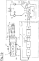
- the Fig. 1a and Fig. 1b each show an internal combustion engine 1 with exhaust gas flow paths 2, which are formed by an exhaust line 3 and an exhaust gas recirculation line 4.
- the exhaust gas recirculation line 4 is used for external exhaust gas recirculation between the exhaust system 22 and the intake system 23 of the internal combustion engine 1.
- an exhaust gas aftertreatment device 5 is arranged, which in the exemplary embodiment has a diesel oxidation catalytic converter 6, a diesel particulate filter 7, an SCR catalytic converter 8 and a blocking catalytic converter 9.
- a diesel oxidation catalytic converter 6 Upstream of the SCR catalyst 8, an NH 3 -containing additive can be supplied via an injection device 10.
- a mixer 11 is used for mixing and vaporizing the injected additive in the exhaust stream.
- a heat recovery system 12 with a closed working medium circuit 13 for a working medium for example ethanol
- a working medium for example ethanol
- Reference numeral 17 denotes a capacitor.
- a bypass line 18 is provided, which branches off from the exhaust line 3 upstream of the first evaporator 14 and opens again into the exhaust line 3 downstream of the first evaporator 14.
- Reference numeral 19 designates a control member formed, for example, by a switching flap for switching the flow of exhaust gas between the flow path through the first evaporator 14 and the bypass line 18.
- a second evaporator 14a may be provided in the exhaust gas recirculation line 4, which may be incorporated into the working medium circuit 13 of the heat recovery system 12 upstream or downstream of the first evaporator 14.
- the second evaporator 14a downstream of the first evaporator 14 is integrated into the working medium circuit 13.
- the second evaporator 14a may be disposed in a second working medium circuit 13a of the heat recovery system 12 having a second pump 15a, a second expansion machine 16a, and a second condenser 17a, as in FIG Fig. 1b is shown.
- an NH 3 sensor 20 Downstream of the first evaporator 14, an NH 3 sensor 20 is arranged in the exhaust line 3. Another NH 3 sensor 20 a may be disposed downstream of the second evaporator 20 a in the exhaust gas recirculation line 4. The NH 3 sensors 20, 20a communicate with a control and / or evaluation unit 21.
- the NH 3 sensors 20, 20a each have a cross-sensitivity to the working medium - in the present case to ethanol -, or to a component of the working medium. This means that the NH 3 sensors detect not only NH 3 readings by ammonia actually contained in the exhaust, but also by the cross-sensitivity initiating substance. If there is a leak in the region of the evaporator 14 or 14a, this is reflected in the output increased NH 3 values of the NH 3 sensors 20 or 20a.
- this NH 3 reading is subjected to a plausibility check by injecting the injection amount of the NH 3 -containing additive through the injector 10 upstream of the SCR.
- Storage catalytic converter 8 for example, using a closed loop - is reduced or stopped, and it is examined whether after a defined first waiting time (for example, 30 to 60 seconds), a substantial reduction of the measured NH 3 concentration occurs. Furthermore, if an abnormally high NH 3 reading is detected, a leak at the first evaporator 14 may be inferred.
- the inventive method for detecting a leak in the heat recovery system 12 during overrun operation or when switching from engine operation to overrun operation can be performed.
- the injection of an NH 3 -containing additive upstream of the SCR storage catalytic converter 8 is stopped and it is investigated whether a significant reduction of the measured NH 3 concentration occurs after a defined second waiting time of, for example, 30 to 60 seconds. If there is no significant reduction in the NH 3 reading, a leak at the first 14 can be inferred.
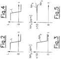
- the Fig. 2 and Fig. 3 show a time profile of the load L and the NH 3 readings for a leak-free heat recovery system 12 during a changeover of the internal combustion engine 1 to overrun operation. Usually, during the overrun operation, the injection of the NH 3 additive is stopped. Clear It can be seen that the measured NH 3 value of the first NH 3 sensor 20 is drastically reduced - there is thus no leakage.
- the 4 and FIG. 5 show a switch to overrun operation when a leak in the first evaporator 14 is present. In this case, there is no reduction in the NH 3 measured value. On the contrary - due to the unchanged leakage and the lower gas flow through the exhaust gas flow path in overrun it can even increase the NH 3 value, as the dashed line shows. In this case, it is possible to clearly conclude that the evaporator 14 is leaking and that a corresponding leakage warning is issued to the driver.
- the main advantage of the present invention is the fact that no additional elaborate leak detectors must be installed.
- an NH 3 sensor 14 which is already fitted as standard in the exhaust gas line, but may be used at a point downstream of the evaporator in the exhaust gas flow path 2, can be used to carry out reliable leakage tests.
Landscapes
- Engineering & Computer Science (AREA)
- Chemical & Material Sciences (AREA)
- Combustion & Propulsion (AREA)
- General Engineering & Computer Science (AREA)
- Mechanical Engineering (AREA)
- Physics & Mathematics (AREA)
- Chemical Kinetics & Catalysis (AREA)
- Life Sciences & Earth Sciences (AREA)
- Sustainable Development (AREA)
- Sustainable Energy (AREA)
- Thermal Sciences (AREA)
- Health & Medical Sciences (AREA)
- Toxicology (AREA)
- General Physics & Mathematics (AREA)
- Exhaust Gas After Treatment (AREA)
Description
- Die Erfindung betrifft ein Verfahren zur Erkennung einer undichten Stelle in einem Wärmerückgewinnungssystem einer Brennkraftmaschine eines Kraftfahrzeugs, wobei das Wärmerückgewinnungssystem zumindest ein insbesondere brennbares Arbeitsmedium und einen Arbeitsmediumkreis mit zumindest einem Verdampfer, einer Pumpe und zumindest einer Expansionsmaschine aufweist, wobei der Verdampfer vom Abgas der Brennkraftmaschine durchströmt wird. Weiters betrifft die Erfindung eine Brennkraftmaschine mit einem Wärmerückgewinnungssystem, welches zumindest ein insbesondere brennbares Arbeitsmedium und einen Arbeitsmediumkreis mit zumindest einem Verdampfer, einer Pumpe und zumindest einer Expansionsmaschine aufweist, wobei der Verdampfer stromabwärts eines SCR-Katalysators im Abgasströmungsweg der Brennkraftmaschine angeordnet ist, zur Durchführung dieses Verfahrens.
- Beim Betrieb eines Systems zur Wärmerückgewinnung mit einem brennbaren Arbeitsmedium in Verbindung mit einer Brennkraftmaschine und einem Verdampfer, insbesondere einem EG-Verdampfer (EGR-Verdampfer: EGR = Exhaust Gas Recirculation) ist das Erkennen von Undichtheiten im System von hoher Priorität. Leckagen in einem Wärmerückgewinnungssystem können unter anderem zu folgenden kritischen Szenarien führen:
- Austritt des Arbeitsmediums in die Umgebung - führt zu Brandgefahr bei Verwendung eines brennbaren Arbeitsmediums wie beispielsweise Ethanol.
- Eintritt des brennbaren Arbeitsmediums in die Brennkraftmaschine - verursacht Schaden, wenn zum Beispiel das Arbeitsmedium über einen EGR-Verdampfer in den Brennraum gelangt.
- Überhitzung von Systemkomponenten durch zu geringen Füllstand des Arbeitsmediums - kann zum Beispiel zu Überhitzung des Abgasverdampfers bei zu geringem Arbeitsmedienmassenstrom führen.
- Zur Feststellung einer Leckage in einem Wärmerückgewinnungssystem sind beispielsweise folgende Verfahren bekannt:
- Überwachung des Füllstandes des Arbeitsmediums im Ausgleichsbehälter mittels eines Füllstandssensors. Bei zu geringem Füllstand wird auf eine Undichtheit geschlossen.
- Dichtheitsprüfung durch unter Druck setzen des deaktivierten, kalten Systems und anschließendes Beobachten des Druckgradientens. Ein zu rascher Druckabfall deutet auf eine Undichtheit hin.
- Messen der elektrischen Leitfähigkeit der Isolierung des Wärmerückgewinnungssystems. Eine Änderung der Leitfähigkeit ist ein Anzeichen für eine Undichtheit.
- Die
DE 10 2011 117 054 A1 beschreibt eine Vorrichtung zur Energierückgewinnung aus einem Abwärmestrom einer Brennkraftmaschine in einem Fahrzeug mit einem Arbeitsmedium-Kreislauf, wobei zur Erkennung von Undichtheiten im Verdampfer des Arbeitsmedium-kreislaufes ein mit einer Steuereinheit gekoppelter Füllstandssensor eingesetzt wird, um den Füllstand in einem Arbeitsmediumbehälter zu überwachen. - Die
US 2002/0182127 A1 offenbart eine Einrichtung zum Entfernen von bei der Verbrennung auftretenden Stickoxiden im Abgas einer Brennkraftmaschine, wobei dem Abgas ein NH3 enthaltendes Reduktionsmittel zugeführt wird. Zum Messen der NH3-Konzentration im Abgas wird ein NH3-Sensor eingesetzt. - Aus der
DE 10 2008 057 202 A1 ist es bekannt, die Menge eines in einem Clausius-Rankine-Kreis zirkulierenden Arbeitsfluids mithilfe einer Steuereinrichtung und eines Steuerventils einzustellen
DieDE 42 17 552 C1 offenbart einen Katalysator zur selektiven katalytischen Reduktion von Stickoxiden aus Abgasen, der zwei NH3-Sensoren in einer Dosiereinrichtung für die überstöchiometrische Zugabe von NH3 umfasst. - Die
US 6,526,358 B1 beschreibt beispielsweise ein Verfahren zur Erkennung von Lecks und Blockaden in einem Fluidkreislauf, wobei Druck, Temperatur und Durchflussrate an verschiedenen Stellen des Kreislaufs gemessen und in Beziehung gesetzt werden. - Die
JP 2010-156314 A - Bekannte Verfahren haben den Nachteil, dass sie entweder nur im deaktivierten Zustand des Fahrzeuges durchgeführt werden können und/oder dass Einrichtungen wie zusätzliche Sensoren erforderlich sind.
- Aufgabe der Erfindung ist es, auf möglichst einfache Weise Undichtheiten im Verdampfer eines Wärmerückgewinnungssystems frühzeitig und zuverlässig erkennen zu können. Erfindungsgemäß wird diese Aufgabe durch das Verfahren des Anspruchs 1 und die entsprechende Vorrichtung des Anspruchs 8 gelöst.
- Erfindungsgemäß erfolgt dies dadurch, dass zumindest ein NH3-Sensor im Abgasströmungsweg stromabwärts des Verdampfers angeordnet wird und mit diesem NH3-Sensor das Abgas - vorzugsweise im Normalbetrieb der Brennkraftmaschine - gemessen wird, wobei bei Auftreten zumindest eines abnormal hohen NH3-Messwertes - vorzugsweise nach Durchführen einer Plausibilitätsprüfung - auf eine Undichtheit des Verdampfers geschlossen wird, wobei als Arbeitsmedium eine chemische Substanz gewählt wird oder dem Arbeitsmedium eine chemische Substanz beigesetzt wird, auf welche der NH3-Sensor reagiert. Der bei einem SCR-Katalysator ohnehin standardmäßig vorgesehene NH3-Sensor wird also an einer Stelle im Abgasströmungsweg platziert, welche stromabwärts einer möglicherweise auftretenden Leckage des Verdampfers des Wärmerückgewinnungssystems liegt. Unter Leckage ist eine Undichtheit zu verstehen, wobei das Arbeitsmedium unkontrolliert aus dem Verdampfer entweicht.
- Voraussetzung für eine Aussage über die Dichtheit des Wärmerückgewinnungssystems ist, dass der NH3-Sensor auf ein aus dem Verdampfer austretendes Arbeitsmedium anspricht. Um dies zu erreichen wird als Arbeitsmedium eine chemische Substanz gewählt oder es wird dem Arbeitsmedium eine chemische Substanz beigesetzt, auf welche der NH3-Sensor reagiert, wobei vorzugsweise der NH3-Sensor in Bezug auf diese Substanz eine Querempfindlichkeit aufweist. Unter Querempfindlichkeit wird im Allgemeinen die Empfindlichkeit eines Sensors auf andere Größen als die zu messende Größe verstanden, wodurch es zu Verfälschungen im Messergebnis kommen kann. Im vorliegenden Fall bedeutet Querempfindlichkeit des NH3-Sensors, dass dieser eine Empfindlichkeit auf andere chemische Substanzen als Ammoniak aufweist. Es ist beispielsweise bekannt, dass NH3-Sensoren eine Querempfindlichkeit in Bezug auf NOx, insbesondere NO2 aufweisen.
- Überraschenderweise hat sich gezeigt, dass NH3-Sensoren auch eine deutliche Querempfindlichkeit gegenüber weiteren chemischen Stoffen wie etwa Ethanol aufweist, welches üblicherweise als Arbeitsmedium Verwendung findet. Die vorliegende Erfindung macht sich in einer bevorzugten Ausführungsvariante der Erfindung die Tatsache zunutze, dass NH3-Sensoren nicht nur auf Ammoniak, sondern auch zum Beispiel auf Ethanol reagieren. Somit kann auf eine Leckage des Wärmerückgewinnungssystems geschlossen werden, wenn ein abnormal hoher NH3-Messwert festgestellt wird. Abnormal bedeutet in diesem Zusammenhang, dass der festgestellte NH3-Messwert höher ist, als ein dem momentanen Betriebspunkt entsprechender Wert erlauben würde. Um dies zu verifizieren oder falsifizieren, wird vorteilhafterweise in Bezug auf den festgestellten NH3-Messwert eine Plausibilitätsprüfung durchgeführt. Ist der Verdampfer stromabwärts eines SCR-Katalysators angeordnet, so beinhaltet die Plausibilitätsprüfung, ob der erhöhte NH3-Messwert der Einspritzung eines NH3-hältigen Additives geschuldet werden kann.
- Ein SCR-Katalysator (SCR=Selective Catalytic Reduction) im Abgasstrang einer Brennkraftmaschine dient der Reduktion von bei der Verbrennung auftretenden Stickoxiden. Für die Reaktion wird beispielsweise NH3 benötigt, welches dem Abgas stromaufwärts des SCR-Katalysators in Form einer wässrigen Harnstofflösung beigemischt wird. Die Produkte der Reaktion sind H2O (Wasser) und N2 (Stickstoff). Zur Regelung der exakten Dosierung der Harnstofflösung ist üblicherweise stromabwärts des SCR-Katalysators im Abgasstrang zumindest ein NH3-Sensor verbaut. Im Rahmen der vorliegenden Erfindung ist dieser NH3-Sensor nicht - wie üblich - unmittelbar nach dem SCR-Katalysator oder einem dem SCR-Katalysator eventuell nachgeschalteten Ammoniak-Sperrkatalysator (ASC), sondern erst stromabwärts eines nach dem SCR-Katalysator bzw. Ammoniak-Sperrkatalysator angeordneten Verdampfers des Abwärmerückgewinnungssystems angeordnet. Der Sperrkatalysator dient dazu um gegebenenfalls überschüssiges NH3 stromabwärts des SCR-Speicherkatalysators 8 zu vermindern bzw. zu entfernen, wobei Ammoniak zu N2 und H2O oxidiert wird.
- Um Einflüsse der Abgasnachbehandlung auf den erhöhten NH3-Messwert ausschließen zu können, ist gemäß einer vorteilhaften Ausführungsvariante vorgesehen, dass im normalen Motorbetrieb der Brennkraftmaschine, bei Auftreten eines abnormal hohen Messwertes eine Plausibilitätsprüfung durchgeführt wird, indem die Einspritzmenge eines NH3-hältigen Additives stromaufwärts des SCR-Speicherkatalysators - vorzugsweise unter Verwendung eines geschlossenen Regelkreises - reduziert oder gestoppt wird, und untersucht wird, ob nach Ablauf einer definierten ersten Wartezeit eine wesentliche Verminderung der gemessenen NH3-Konzentration eintritt, und falls weiterhin ein abnormal hoher NH3-Messwert festgestellt wird, auf eine Undichtheit des Verdampfers geschlossen wird.
- Alternativ oder zusätzlich zur Leckage Untersuchung m Motorbetrieb kann auch gemäß einer vorteilhaften Ausführung der Erfindung vorgesehen sein, dass im Schubbetrieb der Brennkraftmaschine die Einspritzung eines NH3-hältigen Additives stromaufwärts des SCR-Speicherkatalysators reduziert oder gestoppt wird, und untersucht wird, ob nach Ablauf einer definierten zweiten Wartezeit eine wesentliche Verminderung der gemessenen NH3-Konzentration eintritt, und falls weiterhin ein abnormal hoher NH3-Messwert festgestellt wird, auf eine Undichtheit des Verdampfers geschlossen wird.
- Die erste und/oder zweite Wartezeit sollte beispielsweise zumindest 30 bis 60 Sekunden betragen, damit sich ein Reaktionsgleichgewichtszustand einstellen kann.
- Alternativ oder zusätzlich zu einem Verdampfer im Abgasstrang stromabwärts des SCR-Katalysators kann in einer Abgasrückführleitung ein (weiterer) Verdampfer des Abwärmerückgewinnungssystems angeordnet sein. In diesem Fall können in den meisten Fällen bei Feststellen eines abnormal erhöhten NH3-Messertes andere Ursachen als eine Leckage des Verdampfers ausgeschlossen werden.
- Die Feststellung einer Leckage des zweiten Verdampfers kann - beispielsweise im Schubbetrieb - ebenfalls durch den stromabwärts des ersten Verdampfers angeordneten ersten NH3-Sensor im Abgasstrang erfolgen, vorausgesetzt, dass das an der Leckagestelle des zweiten Verdampfers austretende Arbeitsmedium des Arbeitsmediumkreises nicht innerhalb der Brennräume oder im Abgasnachbehandlungssystem eine chemische Reaktion eingeht, dessen Endprodukt durch den NH3-Sensor nicht mehr erfasst werden kann. Um dieses Risiko auszuschließen, kann in Weiterführung der Erfindung vorgesehen sein, dass ein zweiter NH3-Sensor stromabwärts des zweiten Verdampfers in der Abgasrückführleitung angeordnet ist, über welchen Leckagen des zweiten Verdampfers direkt festgestellt werden können.
- Ein abnormal hoher NH3-Messwert liegt beispielsweise dann vor, wenn der durchschnittliche NH3-Messwert über 10 ppm liegt.
- Wenn unzweifelhaft eine Undichtheit des Verdampfers festgestellt wird, kann ein entsprechendes Warnsignal an den Fahrer ausgegeben und/oder ein entsprechender Eintrag im Fehlercode im On-Board-Diagnosesystem eingetragen werden.
- Die Erfindung wird im Folgenden anhand eines in den Figuren gezeigten nicht einschränkenden Ausführungsbeispiels näher erläutert. Darin zeigen:
- Fig. 1a
- schematisch eine erfindungsgemäße Brennkraftmaschine in einer ersten Ausführungsvariante;
- Fig. 1b
- schematisch eine erfindungsgemäße Brennkraftmaschine in einer zweiten Ausführungsvariante;
- Fig. 2
- und
Fig. 3 einen zeitlichen Verlauf der Last und der NH3-Messwerte für ein leckagefreies Wärmerückgewinnungssystem; und - Fig. 4
- und
Fig. 5 einen zeitlichen Verlauf der Last und der NH3-Messwerte für ein leckagebehaftetes Wärmerückgewinnungssystem, bei Anwendung der vorliegenden Erfindung. - Die
Fig. 1a undFig. 1b zeigen jeweils eine Brennkraftmaschine 1 mit Abgasströmungswegen 2, welche durch einen Abgasstrang 3 und eine Abgasrückführleitung 4 gebildet sind. Die Abgasrückführleitung 4 dient zur externen Abgasrückführung zwischen Auslasssystem 22 und Einlasssystem 23 der Brennkraftmaschine 1. - Im Abgasstrang 3 ist eine Abgasnachbehandlungseinrichtung 5 angeordnet, welches im Ausführungsbeispiel einen Diesel-Oxidationskatalysator 6, einen Diesel-Partikelfilter 7, einen SCR-Katalysator 8 und einen Sperrkatalysator 9 aufweist. Stromaufwärts des SCR-Katalysators 8 kann ein NH3-hältiges Additiv über eine Einspritzeinrichtung 10 zugeführt werden. Ein Mischer 11 dient zum Mischen und Verdampfen des eingespritzten Additivs im Abgasstrom.
- Zur Rückgewinnung der Abgasabwärme ist ein Wärmerückgewinnungssystem 12 mit einem geschlossenen Arbeitsmediumkreis 13 für ein Arbeitsmedium, beispielsweise Ethanol, vorgesehen, welches zumindest einen ersten Verdampfer 14, eine Pumpe 15 und zumindest eine Expansionsmaschine 16 aufweist. Mit Bezugszeichen 17 ist ein Kondensator bezeichnet. Zur abgasseitigen Umgehung des ersten Verdampfers 14 ist eine Umgehungsleitung 18 vorgesehen, welche stromaufwärts des ersten Verdampfers 14 vom Abgasstrang 3 abzweigt und stromabwärts des ersten Verdampfers 14 wieder in den Abgasstrang 3 einmündet. Mit Bezugszeichen 19 ist ein beispielsweise durch eine Umschaltklappe gebildetes Steuerorgan zum Umschalten der Abgasströmung zwischen den Strömungsweg durch den ersten Verdampfer 14 und die Umgehungsleitung 18 bezeichnet.
- Optional kann ein zweiter Verdampfer 14a in der Abgasrückführleitung 4 vorgesehen sein, welcher stromaufwärts oder stromabwärts des ersten Verdampfers 14 in den Arbeitsmediumkreis 13 des Wärmerückgewinnungssystems 12 eingebunden sein kann. Bei der in
Fig. 1a dargestellten ersten Ausführungsvariante ist der zweite Verdampfer 14a stromabwärts des ersten Verdampfers 14 in den Arbeitsmediumkreis 13 eingebunden. Alternativ dazu kann der zweite Verdampfer 14a aber auch in einen eine zweite Pumpe 15a, eine zweite Expansionsmaschine 16a und einen zweiten Kondensor 17a aufweisenden zweiten Arbeitsmediumkreis 13a des Wärmerückgewinnungssystems 12 angeordnet sein, wie inFig. 1b gezeigt ist. - Stromabwärts des ersten Verdampfers 14 ist im Abgasstrang 3 ein NH3-Sensor 20 angeordnet. Ein weiterer NH3-Sensor 20a kann stromabwärts des zweiten Verdampfers 20a in der Abgasrückführleitung 4 angeordnet sein. Die NH3-Sensoren 20, 20a stehen mit einer Steuer- und/oder Auswerteeinheit 21 in Verbindung.
- Die NH3-Sensoren 20, 20a weisen jeweils eine Querempfindlichkeit zu dem Arbeitsmedium - im vorliegenden Fall also zu Ethanol -, bzw. zu einer Komponente des Arbeitsmediums auf. Dies bedeutet, dass die NH3-Sensoren nicht nur NH3-Messwerte durch tatsächlich im Abgas enthaltenen Ammoniak, sondern auch durch die die Querempfindlichkeit initiierende Substanz erfassen. Kommt es zu einer Leckage im Bereich des Verdampfers 14 bzw. 14a, so schlägt sich dies also in den ausgegebenen erhöhten NH3-Messwerten der NH3-Sensoren 20 bzw. 20a nieder.
- Bei Auftreten eines abnormal hohen NH3-Messwertes des ersten NH3-Sensors 20 während des normalen Motorbetriebes der Brennkraftmaschine 1 wird dieser NH3-Messwert einer Plausibilitätsprüfung unterzogen, indem die Einspritzmenge des NH3-hältigen Additives durch die Einspritzeinrichtung 10 stromaufwärts des SCR-Speicherkatalysators 8 beispielsweise unter Verwendung eines geschlossenen Regelkreises - reduziert oder gestoppt wird, und untersucht wird, ob nach Ablauf einer definierten ersten Wartezeit (zum Beispiel 30 bis 60 Sekunden) eine wesentliche Verminderung der gemessenen NH3-Konzentration eintritt. Wenn weiterhin ein abnormal hoher NH3-Messwert festgestellt wird, kann auf eine Undichtheit am ersten Verdampfer 14 geschlossen werden.
- Alternativ zum Motorbetrieb kann das erfindungsgemäße Verfahren zum Erkennen einer undichten Stelle im Wärmerückgewinnungssystem 12 auch während des Schubbetriebes bzw. beim Umschalten vom Motorbetrieb auf Schubbetrieb durchgeführt werden. Dabei wird im Schubbetrieb der Brennkraftmaschine 1 die Einspritzung eines NH3-hältigen Additives stromaufwärts des SCR-Speicherkatalysators 8 gestoppt und untersucht, ob nach Ablauf einer definierten zweiten Wartezeit von beispielsweise 30 bis 60 Sekunden eine wesentliche Verminderung der gemessenen NH3-Konzentration eintritt. Wenn keine wesentliche Verminderung des NH3-Messwertes festzustellen ist, kann auf eine Undichtheit am ersten 14 geschlossen werden. Kann nicht ausgeschlossen werden, dass ein aus dem zweiten Verdampfer 14a eventuell austretendes Arbeitsmedium in der Brennkraftmaschine 1 oder im Abgasnachbehandlungssystem 5 eliminiert oder chemisch verändert wird, so ist es vorteilhaft, einen zweiten NH3-Sensor 20a unmittelbar stromabwärts des zweiten Verdampfers 14a in der Abgasrückführleitung 4 einzusetzen, über welchen Leckagen des zweiten Verdampfers 14a direkt erfasst werden können.
- Die
Fig. 2 und Fig. 3 zeigen einen zeitlichen Verlauf der Last L und der NH3-Messwerte für ein leckagefreies Wärmerückgewinnungssystem 12 während einer Umschaltung der Brennkraftmaschine 1 auf Schubbetrieb. Üblicherweise wird während des Schubbetriebs die Einspritzung des NH3-Additivs gestoppt. Deutlich ist erkennbar, dass der gemessene NH3-Messwert des ersten NH3-Sensors 20 sich drastisch vermindert - es liegt somit keine Leckage vor. - Die
Fig. 4 und Fig. 5 zeigen dagegen eine Umschaltung auf Schubbetrieb, wenn eine Leckage im ersten Verdampfer 14 vorliegt. In diesem Fall kommt es zu keiner Verminderung des NH3-Messwertes. Im Gegenteil - auf Grund der unveränderten Leckage und des geringeren Gasdurchsatzes durch den Abgasströmungsweg im Schubbetrieb kann es sogar noch zu einer Steigerung des NH3-Messwertes kommen, wie die strichlierte Linie zeigt. In diesem Fall kann eindeutig auf eine Leckage des Verdampfers 14 geschlossen und eine entsprechende Leckagewarnung an den Fahrer ausgegeben werden. - Der Hauptvorteil der vorliegenden Erfindung ist darin zu sehen, dass keine zusätzlichen aufwändigen Leckagedetektoren verbaut werden müssen. Im Idealfall kann ein bereits serienmäßig im Abgasstrang angeordneter NH3-Sensor 14 - allerdings an einer Stelle stromabwärts des Verdampfers im Abgasströmungsweg 2 - verwendet werden, um zuverlässige Leckageuntersuchungen durchzuführen.
Claims (11)
- Verfahren zur Erkennung einer undichten Stelle in einem Wärmerückgewinnungssystem (12) einer Brennkraftmaschine (1) eines Kraftfahrzeugs, wobei das Wärmerückgewinnungssystem (12; 12a) zumindest ein insbesondere brennbares Arbeitsmedium und einen Arbeitsmediumkreis (13; 13a) mit zumindest einem Verdampfer (14; 14a), einer Pumpe (15; 15a) und zumindest einer Expansionsmaschine (16; 16a) aufweist, wobei der Verdampfer (14;14a) vom Abgas der Brennkraftmaschine (1) durchströmt wird, dadurch gekennzeichnet, dass zumindest ein NH3-Sensor (20; 20a) im Abgasströmungsweg (2) stromabwärts des Verdampfers (14; 14a) angeordnet wird und mit diesem NH3-Sensor (20; 20a) das Abgas im Abgasströmungsweg (2) gemessen wird, wobei beim Auftreten zumindest eines abnormal hohen NH3-Messwertes - vorzugsweise nach Durchführen einer Plausibilitätsprüfung - auf eine Undichtheit des Verdampfers (14; 14a) geschlossen wird, wobei als Arbeitsmedium eine chemische Substanz gewählt wird oder dem Arbeitsmedium eine chemische Substanz beigesetzt wird, auf welche der NH3-Sensor (20; 20a) reagiert.
- Verfahren nach Anspruch 1, dadurch gekennzeichnet, dass der NH3-Sensor (20; 20a) zur chemischen Substanz eine Querempfindlichkeit aufweist.
- Verfahren nach Anspruch 1 oder 2, dadurch gekennzeichnet, dass im Motorbetrieb der Brennkraftmaschine (1) bei Auftreten eines abnormal hohen NH3-Messwertes eine Plausibilitätsprüfung durchgeführt wird, indem die Einspritzmenge eines NH3-hältigen Additives stromaufwärts des SCR-Speicherkatalysators (8) - vorzugsweise unter Verwendung eines geschlossenen Regelkreises - reduziert oder gestoppt wird, und untersucht wird, ob nach Ablauf einer definierten ersten Wartezeit eine wesentliche Verminderung der gemessenen NH3-Konzentration eintritt, und falls weiterhin ein abnormal hoher NH3-Messwert festgestellt wird, auf eine Undichtheit des Verdampfers (14) geschlossen wird.
- Verfahren nach einem der Ansprüche 1 bis 3, dadurch gekennzeichnet, dass im Schubbetrieb der Brennkraftmaschine (1) die Einspritzung eines NH3-hältigen Additives stromaufwärts des SCR-Speicherkatalysators (8) reduziert oder gestoppt wird, und untersucht wird, ob nach Ablauf einer definierten zweiten Wartezeit eine wesentliche Verminderung der gemessenen NH3-Konzentration eintritt, und - falls weiterhin ein abnormal hoher NH3-Messwert festgestellt wird - auf eine Undichtheit des Verdampfers (14) geschlossen wird.
- Verfahren nach einem der Ansprüche 1 bis 4, dadurch gekennzeichnet, dass ein abnormal hoher NH3-Messwert festgestellt wird, wenn der durchschnittliche NH3-Messwert über 10 ppm liegt.
- Verfahren nach einem der Ansprüche 1 bis 5, dadurch gekennzeichnet, dass die erste und/oder zweite Wartezeit zumindest 30 bis 60 Sekunden beträgt.
- Verfahren nach einem der Ansprüche 1 bis 6, dadurch gekennzeichnet, dass - wenn eine Undichtheit des Verdampfers (14; 14a) festgestellt wird - ein entsprechendes Warnsignal ausgegeben wird.
- Brennkraftmaschine, mit einem Wärmerückgewinnungssystem (12), welches zumindest ein insbesondere brennbares Arbeitsmedium und einen Arbeitsmediumkreis (13) mit zumindest einem Verdampfer (14; 14a), einer Pumpe (15) und zumindest einer Expansionsmaschine (16) aufweist, wobei der Verdampfer (14; 14a) in einem Abgasströmungsweg (2) der Brennkraftmaschine (1) angeordnet ist, zur Durchführung des Verfahrens nach einem der Ansprüche 1 bis 7, dadurch gekennzeichnet, dass zumindest ein NH3-Sensor (20; 20a) stromabwärts zumindest eines im Abgasströmungsweg (2) angeordneten Verdampfers (14; 14a) angeordnet ist und mit diesem NH3-Sensor (20; 20a) das Abgas im Abgasströmungsweg (2) der Brennkraftmaschine (1) messbar ist, wobei der NH3 Sensor (20; 20a) mit einer elektronischen Steuer- und/oder Auswerteeinheit (21) verbunden ist.
- Brennkraftmaschine (1) nach Anspruch 8, dadurch gekennzeichnet, dass ein erster Verdampfer (14) in einem den Abgasströmungsweg (2) bildenden Abgasstrang (3) der Brennkraftmaschine (1) stromabwärts eines SCR-Katalysators (8) angeordnet ist, wobei ein erster NH3-Sensor (20) stromabwärts des ersten Verdampfers (14) im Abgasstrang (3) angeordnet ist, und wobei vorzugsweise zwischen dem SCR-Katalysator (8) und dem ersten Verdampfer (14) ein Sperrkatalysator (9) für NH3 angeordnet ist.
- Brennkraftmaschine (1) nach Anspruch 9, dadurch gekennzeichnet, dass der erste Verdampfer (14) durch eine Umgehungsleitung (18) umgehbar ist, welche stromaufwärts des ersten Verdampfers (14) vom Abgasstrang (3) abzweigt und stromabwärts des ersten Verdampfers (14) wieder in den Abgasstrang (3) einmündet, wobei vorzugsweise der erste NH3-Sensor (20) stromabwärts der Mündung der Umgehungsleitung (18) in den Abgasstrang (3) angeordnet ist.
- Brennkraftmaschine (1) nach einem der Anspruch 8 bis 10, dadurch gekennzeichnet, dass ein zweiter Verdampfer (14a) in einer den Abgasströmungsweg (2) bildenden Abgasrückführleitung (4) der Brennkraftmaschine (1) angeordnet ist, wobei vorzugsweise ein zweiter NH3-Sensor (20a) stromabwärts des zweiten Verdampfers (14a) in der Abgasrückführleitung (4) angeordnet ist.
Applications Claiming Priority (2)
| Application Number | Priority Date | Filing Date | Title |
|---|---|---|---|
| ATA50640/2016A AT518522B1 (de) | 2016-07-18 | 2016-07-18 | Verfahren zur erkennung einer undichten stelle in einem wärmerückgewinnungssystem |
| PCT/AT2017/060175 WO2018014058A1 (de) | 2016-07-18 | 2017-07-12 | Verfahren zur erkennung einer undichten stelle in einem wärmerückgewinnungssystem |
Publications (2)
| Publication Number | Publication Date |
|---|---|
| EP3485148A1 EP3485148A1 (de) | 2019-05-22 |
| EP3485148B1 true EP3485148B1 (de) | 2019-09-11 |
Family
ID=59387853
Family Applications (1)
| Application Number | Title | Priority Date | Filing Date |
|---|---|---|---|
| EP17742937.0A Active EP3485148B1 (de) | 2016-07-18 | 2017-07-12 | Verfahren zur erkennung einer undichten stelle in einem wärmerückgewinnungssystem |
Country Status (5)
| Country | Link |
|---|---|
| US (1) | US10815834B2 (de) |
| EP (1) | EP3485148B1 (de) |
| CN (1) | CN109690030B (de) |
| AT (1) | AT518522B1 (de) |
| WO (1) | WO2018014058A1 (de) |
Families Citing this family (2)
| Publication number | Priority date | Publication date | Assignee | Title |
|---|---|---|---|---|
| AT516615B1 (de) * | 2015-08-28 | 2016-07-15 | Avl List Gmbh | Verfahren zur Erkennung einer undichten Stelle in einem Wärmerückgewinnungssystem einer Brennkraftmaschine |
| CN114526178B (zh) * | 2022-02-25 | 2024-06-25 | 招商局金陵鼎衡船舶(扬州)有限公司 | 一种氨动力船舶内燃机燃料供给装置 |
Family Cites Families (23)
| Publication number | Priority date | Publication date | Assignee | Title |
|---|---|---|---|---|
| DE4217552C1 (de) * | 1992-05-27 | 1993-08-19 | Mercedes-Benz Aktiengesellschaft, 7000 Stuttgart, De | |
| US6526358B1 (en) | 1999-10-01 | 2003-02-25 | General Electric Company | Model-based detection of leaks and blockages in fluid handling systems |
| DE10126456B4 (de) | 2001-05-31 | 2004-05-19 | Daimlerchrysler Ag | Vorrichtung und Verfahren zur Entfernung von Stickoxiden aus dem Abgas mager betriebener Brennkraftmaschinen |
| JP3730904B2 (ja) * | 2001-11-21 | 2006-01-05 | 本田技研工業株式会社 | 熱交換装置 |
| DE10207984A1 (de) * | 2002-02-25 | 2003-10-23 | Daimler Chrysler Ag | Vorrichtung zur Abgasreinigung und Verfahren hierzu |
| DE102005026032A1 (de) * | 2005-06-03 | 2006-12-07 | Emitec Gesellschaft Für Emissionstechnologie Mbh | Verfahren und Vorrichtung zur Behandlung von Abgasen von Verbrennungskraftmaschinen |
| DE102008057202A1 (de) * | 2008-11-13 | 2010-05-20 | Daimler Ag | Clausius-Rankine-Kreis |
| JP2010156314A (ja) * | 2009-01-05 | 2010-07-15 | Toyota Motor Corp | 廃熱回収装置、及びエンジン |
| DE102010031561A1 (de) * | 2010-07-20 | 2012-01-26 | Behr Gmbh & Co. Kg | System zur Nutzung von Abwärme eines Verbrennungsmotors |
| US8752378B2 (en) * | 2010-08-09 | 2014-06-17 | Cummins Intellectual Properties, Inc. | Waste heat recovery system for recapturing energy after engine aftertreatment systems |
| EP2609318B1 (de) * | 2010-08-27 | 2015-01-07 | Renault Trucks | Motoranordnung bestehend aus einer wärmerückgewinnungsschaltung und einem abgasnachbehandlungssystem |
| JP5201226B2 (ja) * | 2011-02-17 | 2013-06-05 | トヨタ自動車株式会社 | ランキンサイクルシステムの異常検出装置 |
| DE102011117054A1 (de) * | 2011-10-27 | 2012-05-03 | Daimler Ag | Vorrichtung zur Energierückgewinnung aus einem Abwärmestrom einer Verbrennungskraftmaschine in einem Fahrzeug mit einem Arbeitsmedium-Kreislauf und Verfahren zur Leckage-Erkennung in einem Arbeitsmedium-Kreislauf |
| US20140075941A1 (en) * | 2012-09-14 | 2014-03-20 | Kabushiki Kaisha Kobe Seiko Sho (Kobe Steel, Ltd.) | Power generating apparatus and operation method thereof |
| DE102012221153A1 (de) * | 2012-11-20 | 2014-06-05 | Robert Bosch Gmbh | Verfahren zur Überwachung eines Systems zur Energierückgewinnung aus einem Abwärmestrom einer Brennkraftmaschine |
| US9335004B2 (en) * | 2012-12-07 | 2016-05-10 | General Electric Company | Method and system for use in combustion product control |
| WO2014154568A1 (en) * | 2013-03-25 | 2014-10-02 | Dana Belgium N.V. | Waste heat recovery system and a method of controlling the mass flow rate of a positive displacement expander comprised in such a system |
| DK178097B1 (en) * | 2013-10-31 | 2015-05-18 | Man Diesel & Turbo Deutschland | A combustion engine system |
| US9616383B2 (en) * | 2014-02-06 | 2017-04-11 | Johnson Matthey Catalysts (Germany) Gmbh | Compact selective catalytic reduction system for nitrogen oxide reduction in the oxygen-rich exhaust of 500 to 4500 kW internal combustion engines |
| JP2015190466A (ja) * | 2014-03-31 | 2015-11-02 | 株式会社Ihi | 燃焼装置、ガスタービン及び発電装置 |
| DE102014225059B4 (de) * | 2014-12-05 | 2022-01-27 | Robert Bosch Gmbh | Verfahren zum Betrieb einer Abwärmenutzungsanordnung |
| AT516615B1 (de) * | 2015-08-28 | 2016-07-15 | Avl List Gmbh | Verfahren zur Erkennung einer undichten Stelle in einem Wärmerückgewinnungssystem einer Brennkraftmaschine |
| US10557378B2 (en) * | 2016-03-07 | 2020-02-11 | General Electric Technology Gmbh | System and method for regulating condensation of flue gas in a steam generator |
-
2016
- 2016-07-18 AT ATA50640/2016A patent/AT518522B1/de not_active IP Right Cessation
-
2017
- 2017-07-12 WO PCT/AT2017/060175 patent/WO2018014058A1/de not_active Ceased
- 2017-07-12 CN CN201780044737.5A patent/CN109690030B/zh not_active Expired - Fee Related
- 2017-07-12 US US16/318,333 patent/US10815834B2/en not_active Expired - Fee Related
- 2017-07-12 EP EP17742937.0A patent/EP3485148B1/de active Active
Non-Patent Citations (1)
| Title |
|---|
| None * |
Also Published As
| Publication number | Publication date |
|---|---|
| AT518522A4 (de) | 2017-11-15 |
| AT518522B1 (de) | 2017-11-15 |
| CN109690030B (zh) | 2021-10-01 |
| WO2018014058A1 (de) | 2018-01-25 |
| US10815834B2 (en) | 2020-10-27 |
| EP3485148A1 (de) | 2019-05-22 |
| US20190242274A1 (en) | 2019-08-08 |
| CN109690030A (zh) | 2019-04-26 |
Similar Documents
| Publication | Publication Date | Title |
|---|---|---|
| DE102016100403B4 (de) | NOx-SENSOR-DIAGNOSESYSTEM UND -VERFAHREN | |
| DE102008047860B3 (de) | Verfahren zur Dichtheitsprüfung eines Reagenzmittelinjektors | |
| DE102008005988B4 (de) | Verfahren zur Diagnose einer Abgasnachbehandlungsvorrichtung und Vorrichtung zur Durchführung des Verfahrens | |
| DE102004050989B4 (de) | Verfahren zum Betreiben einer Abgasbehandlungsvorrichtung einer Brennkraftmaschine und Vorrichtung zur Durchführung des Verfahrens | |
| DE10056035A1 (de) | Verfahren und Vorrichtung zur Steuerung eines Abgasnachbehandlungssystems | |
| DE112017006232T5 (de) | Diagnostiksysteme und Verfahren zur Reduktionsmittelkonzentration | |
| DE102004022115A1 (de) | Verfahren zum Einbringen eines Reagenzmittels in einen Abgaskanal einer Brennkraftmaschine und Vorrichtung zur Durchführung des Verfahrens | |
| DE102013203580A1 (de) | Verfahren zur Überwachung eines Abgasnachbehandlungssystems | |
| DE102005001119A1 (de) | Verfahren zum Betreiben einer Brennkraftmaschine und Vorrichtung zur Durchführung des Verfahrens | |
| DE102012211705A1 (de) | Verfahren zur Überprüfung eines Stickoxidsensors | |
| DE102007063940B4 (de) | Verfahren zur Diagnose eines eine Abgasbehandlungsvorrichtung enthaltenden Abgasbereichs einer Brennkraftmaschine und Vorrichtung zur Durchführung des Verfahrens | |
| DE102012215394A1 (de) | Vorrichtung zur Diagnose eines Dosiersystems und Verfahren zum Betreiben der Vorrichtung | |
| DE102006013293B4 (de) | Verfahren zur Diagnose einer Abgasnachbehandlungsvorrichtung und Vorrichtung zur Durchführung des Verfahrens | |
| AT518522B1 (de) | Verfahren zur erkennung einer undichten stelle in einem wärmerückgewinnungssystem | |
| DE102004061247B4 (de) | Verfahren zum Betreiben einer Brennkraftmaschine und Vorrichtung zur Durchführung des Verfahrens | |
| DE102016225758B4 (de) | Verfahren und Vorrichtung zur Überwachung eines im Abgassystem einer Brennkraftmaschine angeordneten Partikelfilters und eines Sekundärluftsystems | |
| DE102014205434A1 (de) | Verfahren und Vorrichtung zur Detektion eines Ammoniak-Schlupfes in einem Abgasnachbehandlungssystem | |
| DE102017205322A1 (de) | Verfahren zum Erkennen einer Schädigung eines SCR-Katalysators | |
| DE102004056412B4 (de) | Verfahren zum Betreiben einer Brennkraftmaschine und Vorrichtung zur Durchführung des Verfahrens | |
| EP2923048B1 (de) | Verfahren zum überwachen der bildung von stickstoffdioxid an einem oxidationskatalysator und abgasanlage | |
| DE112017003233B4 (de) | NH3-Schlupferkennung unter Verwendung eines NOx-Sensors | |
| DE102006005863B4 (de) | Verfahren zur Diagnose einer Abgasbehandlungsvorrichtung und Vorrichtung zur Durchführung des Verfahrens | |
| DE102004044506A1 (de) | Verfahren zum Betreiben einer Abgasbehandlungsvorrichtung einer Brennkraftmaschine und Vorrichtung zur Durchführung des Verfahrens | |
| EP3543493B1 (de) | Verfahren und vorrichtung zum überwachen einer scr-abgasnachbehandlungseinrichtung | |
| AT516615B1 (de) | Verfahren zur Erkennung einer undichten Stelle in einem Wärmerückgewinnungssystem einer Brennkraftmaschine |
Legal Events
| Date | Code | Title | Description |
|---|---|---|---|
| STAA | Information on the status of an ep patent application or granted ep patent |
Free format text: STATUS: UNKNOWN |
|
| STAA | Information on the status of an ep patent application or granted ep patent |
Free format text: STATUS: THE INTERNATIONAL PUBLICATION HAS BEEN MADE |
|
| PUAI | Public reference made under article 153(3) epc to a published international application that has entered the european phase |
Free format text: ORIGINAL CODE: 0009012 |
|
| STAA | Information on the status of an ep patent application or granted ep patent |
Free format text: STATUS: REQUEST FOR EXAMINATION WAS MADE |
|
| 17P | Request for examination filed |
Effective date: 20190205 |
|
| AK | Designated contracting states |
Kind code of ref document: A1 Designated state(s): AL AT BE BG CH CY CZ DE DK EE ES FI FR GB GR HR HU IE IS IT LI LT LU LV MC MK MT NL NO PL PT RO RS SE SI SK SM TR |
|
| AX | Request for extension of the european patent |
Extension state: BA ME |
|
| GRAP | Despatch of communication of intention to grant a patent |
Free format text: ORIGINAL CODE: EPIDOSNIGR1 |
|
| STAA | Information on the status of an ep patent application or granted ep patent |
Free format text: STATUS: GRANT OF PATENT IS INTENDED |
|
| RIN1 | Information on inventor provided before grant (corrected) |
Inventor name: GLENSVIG, MICHAEL Inventor name: THALER, MARKUS Inventor name: MAHLER, SUSANNE |
|
| INTG | Intention to grant announced |
Effective date: 20190603 |
|
| GRAS | Grant fee paid |
Free format text: ORIGINAL CODE: EPIDOSNIGR3 |
|
| GRAA | (expected) grant |
Free format text: ORIGINAL CODE: 0009210 |
|
| STAA | Information on the status of an ep patent application or granted ep patent |
Free format text: STATUS: THE PATENT HAS BEEN GRANTED |
|
| AK | Designated contracting states |
Kind code of ref document: B1 Designated state(s): AL AT BE BG CH CY CZ DE DK EE ES FI FR GB GR HR HU IE IS IT LI LT LU LV MC MK MT NL NO PL PT RO RS SE SI SK SM TR |
|
| DAV | Request for validation of the european patent (deleted) | ||
| DAX | Request for extension of the european patent (deleted) | ||
| REG | Reference to a national code |
Ref country code: GB Ref legal event code: FG4D Free format text: NOT ENGLISH |
|
| REG | Reference to a national code |
Ref country code: CH Ref legal event code: EP |
|
| REG | Reference to a national code |
Ref country code: AT Ref legal event code: REF Ref document number: 1178725 Country of ref document: AT Kind code of ref document: T Effective date: 20190915 |
|
| REG | Reference to a national code |
Ref country code: DE Ref legal event code: R096 Ref document number: 502017002297 Country of ref document: DE |
|
| REG | Reference to a national code |
Ref country code: IE Ref legal event code: FG4D Free format text: LANGUAGE OF EP DOCUMENT: GERMAN |
|
| REG | Reference to a national code |
Ref country code: NL Ref legal event code: MP Effective date: 20190911 |
|
| REG | Reference to a national code |
Ref country code: LT Ref legal event code: MG4D |
|
| PG25 | Lapsed in a contracting state [announced via postgrant information from national office to epo] |
Ref country code: FI Free format text: LAPSE BECAUSE OF FAILURE TO SUBMIT A TRANSLATION OF THE DESCRIPTION OR TO PAY THE FEE WITHIN THE PRESCRIBED TIME-LIMIT Effective date: 20190911 Ref country code: BG Free format text: LAPSE BECAUSE OF FAILURE TO SUBMIT A TRANSLATION OF THE DESCRIPTION OR TO PAY THE FEE WITHIN THE PRESCRIBED TIME-LIMIT Effective date: 20191211 Ref country code: SE Free format text: LAPSE BECAUSE OF FAILURE TO SUBMIT A TRANSLATION OF THE DESCRIPTION OR TO PAY THE FEE WITHIN THE PRESCRIBED TIME-LIMIT Effective date: 20190911 Ref country code: NO Free format text: LAPSE BECAUSE OF FAILURE TO SUBMIT A TRANSLATION OF THE DESCRIPTION OR TO PAY THE FEE WITHIN THE PRESCRIBED TIME-LIMIT Effective date: 20191211 Ref country code: LT Free format text: LAPSE BECAUSE OF FAILURE TO SUBMIT A TRANSLATION OF THE DESCRIPTION OR TO PAY THE FEE WITHIN THE PRESCRIBED TIME-LIMIT Effective date: 20190911 Ref country code: HR Free format text: LAPSE BECAUSE OF FAILURE TO SUBMIT A TRANSLATION OF THE DESCRIPTION OR TO PAY THE FEE WITHIN THE PRESCRIBED TIME-LIMIT Effective date: 20190911 |
|
| PG25 | Lapsed in a contracting state [announced via postgrant information from national office to epo] |
Ref country code: RS Free format text: LAPSE BECAUSE OF FAILURE TO SUBMIT A TRANSLATION OF THE DESCRIPTION OR TO PAY THE FEE WITHIN THE PRESCRIBED TIME-LIMIT Effective date: 20190911 Ref country code: GR Free format text: LAPSE BECAUSE OF FAILURE TO SUBMIT A TRANSLATION OF THE DESCRIPTION OR TO PAY THE FEE WITHIN THE PRESCRIBED TIME-LIMIT Effective date: 20191212 Ref country code: AL Free format text: LAPSE BECAUSE OF FAILURE TO SUBMIT A TRANSLATION OF THE DESCRIPTION OR TO PAY THE FEE WITHIN THE PRESCRIBED TIME-LIMIT Effective date: 20190911 Ref country code: LV Free format text: LAPSE BECAUSE OF FAILURE TO SUBMIT A TRANSLATION OF THE DESCRIPTION OR TO PAY THE FEE WITHIN THE PRESCRIBED TIME-LIMIT Effective date: 20190911 Ref country code: ES Free format text: LAPSE BECAUSE OF FAILURE TO SUBMIT A TRANSLATION OF THE DESCRIPTION OR TO PAY THE FEE WITHIN THE PRESCRIBED TIME-LIMIT Effective date: 20190911 |
|
| PG25 | Lapsed in a contracting state [announced via postgrant information from national office to epo] |
Ref country code: PL Free format text: LAPSE BECAUSE OF FAILURE TO SUBMIT A TRANSLATION OF THE DESCRIPTION OR TO PAY THE FEE WITHIN THE PRESCRIBED TIME-LIMIT Effective date: 20190911 Ref country code: EE Free format text: LAPSE BECAUSE OF FAILURE TO SUBMIT A TRANSLATION OF THE DESCRIPTION OR TO PAY THE FEE WITHIN THE PRESCRIBED TIME-LIMIT Effective date: 20190911 Ref country code: PT Free format text: LAPSE BECAUSE OF FAILURE TO SUBMIT A TRANSLATION OF THE DESCRIPTION OR TO PAY THE FEE WITHIN THE PRESCRIBED TIME-LIMIT Effective date: 20200113 Ref country code: RO Free format text: LAPSE BECAUSE OF FAILURE TO SUBMIT A TRANSLATION OF THE DESCRIPTION OR TO PAY THE FEE WITHIN THE PRESCRIBED TIME-LIMIT Effective date: 20190911 Ref country code: NL Free format text: LAPSE BECAUSE OF FAILURE TO SUBMIT A TRANSLATION OF THE DESCRIPTION OR TO PAY THE FEE WITHIN THE PRESCRIBED TIME-LIMIT Effective date: 20190911 |
|
| PG25 | Lapsed in a contracting state [announced via postgrant information from national office to epo] |
Ref country code: CZ Free format text: LAPSE BECAUSE OF FAILURE TO SUBMIT A TRANSLATION OF THE DESCRIPTION OR TO PAY THE FEE WITHIN THE PRESCRIBED TIME-LIMIT Effective date: 20190911 Ref country code: SK Free format text: LAPSE BECAUSE OF FAILURE TO SUBMIT A TRANSLATION OF THE DESCRIPTION OR TO PAY THE FEE WITHIN THE PRESCRIBED TIME-LIMIT Effective date: 20190911 Ref country code: IS Free format text: LAPSE BECAUSE OF FAILURE TO SUBMIT A TRANSLATION OF THE DESCRIPTION OR TO PAY THE FEE WITHIN THE PRESCRIBED TIME-LIMIT Effective date: 20200224 Ref country code: SM Free format text: LAPSE BECAUSE OF FAILURE TO SUBMIT A TRANSLATION OF THE DESCRIPTION OR TO PAY THE FEE WITHIN THE PRESCRIBED TIME-LIMIT Effective date: 20190911 |
|
| REG | Reference to a national code |
Ref country code: DE Ref legal event code: R097 Ref document number: 502017002297 Country of ref document: DE |
|
| PLBE | No opposition filed within time limit |
Free format text: ORIGINAL CODE: 0009261 |
|
| STAA | Information on the status of an ep patent application or granted ep patent |
Free format text: STATUS: NO OPPOSITION FILED WITHIN TIME LIMIT |
|
| PG2D | Information on lapse in contracting state deleted |
Ref country code: IS |
|
| PG25 | Lapsed in a contracting state [announced via postgrant information from national office to epo] |
Ref country code: DK Free format text: LAPSE BECAUSE OF FAILURE TO SUBMIT A TRANSLATION OF THE DESCRIPTION OR TO PAY THE FEE WITHIN THE PRESCRIBED TIME-LIMIT Effective date: 20190911 Ref country code: IS Free format text: LAPSE BECAUSE OF FAILURE TO SUBMIT A TRANSLATION OF THE DESCRIPTION OR TO PAY THE FEE WITHIN THE PRESCRIBED TIME-LIMIT Effective date: 20200112 |
|
| 26N | No opposition filed |
Effective date: 20200615 |
|
| PG25 | Lapsed in a contracting state [announced via postgrant information from national office to epo] |
Ref country code: MC Free format text: LAPSE BECAUSE OF FAILURE TO SUBMIT A TRANSLATION OF THE DESCRIPTION OR TO PAY THE FEE WITHIN THE PRESCRIBED TIME-LIMIT Effective date: 20190911 |
|
| REG | Reference to a national code |
Ref country code: CH Ref legal event code: PL |
|
| REG | Reference to a national code |
Ref country code: BE Ref legal event code: MM Effective date: 20200731 |
|
| PG25 | Lapsed in a contracting state [announced via postgrant information from national office to epo] |
Ref country code: CH Free format text: LAPSE BECAUSE OF NON-PAYMENT OF DUE FEES Effective date: 20200731 Ref country code: LU Free format text: LAPSE BECAUSE OF NON-PAYMENT OF DUE FEES Effective date: 20200712 Ref country code: LI Free format text: LAPSE BECAUSE OF NON-PAYMENT OF DUE FEES Effective date: 20200731 |
|
| PG25 | Lapsed in a contracting state [announced via postgrant information from national office to epo] |
Ref country code: BE Free format text: LAPSE BECAUSE OF NON-PAYMENT OF DUE FEES Effective date: 20200731 |
|
| PG25 | Lapsed in a contracting state [announced via postgrant information from national office to epo] |
Ref country code: IE Free format text: LAPSE BECAUSE OF NON-PAYMENT OF DUE FEES Effective date: 20200712 |
|
| PG25 | Lapsed in a contracting state [announced via postgrant information from national office to epo] |
Ref country code: TR Free format text: LAPSE BECAUSE OF FAILURE TO SUBMIT A TRANSLATION OF THE DESCRIPTION OR TO PAY THE FEE WITHIN THE PRESCRIBED TIME-LIMIT Effective date: 20190911 Ref country code: MT Free format text: LAPSE BECAUSE OF FAILURE TO SUBMIT A TRANSLATION OF THE DESCRIPTION OR TO PAY THE FEE WITHIN THE PRESCRIBED TIME-LIMIT Effective date: 20190911 Ref country code: CY Free format text: LAPSE BECAUSE OF FAILURE TO SUBMIT A TRANSLATION OF THE DESCRIPTION OR TO PAY THE FEE WITHIN THE PRESCRIBED TIME-LIMIT Effective date: 20190911 |
|
| PG25 | Lapsed in a contracting state [announced via postgrant information from national office to epo] |
Ref country code: MK Free format text: LAPSE BECAUSE OF FAILURE TO SUBMIT A TRANSLATION OF THE DESCRIPTION OR TO PAY THE FEE WITHIN THE PRESCRIBED TIME-LIMIT Effective date: 20190911 |
|
| PGFP | Annual fee paid to national office [announced via postgrant information from national office to epo] |
Ref country code: IT Payment date: 20220725 Year of fee payment: 6 Ref country code: GB Payment date: 20220719 Year of fee payment: 6 |
|
| PGFP | Annual fee paid to national office [announced via postgrant information from national office to epo] |
Ref country code: FR Payment date: 20220725 Year of fee payment: 6 |
|
| P01 | Opt-out of the competence of the unified patent court (upc) registered |
Effective date: 20230505 |
|
| REG | Reference to a national code |
Ref country code: AT Ref legal event code: MM01 Ref document number: 1178725 Country of ref document: AT Kind code of ref document: T Effective date: 20220712 |
|
| PG25 | Lapsed in a contracting state [announced via postgrant information from national office to epo] |
Ref country code: SI Free format text: LAPSE BECAUSE OF FAILURE TO SUBMIT A TRANSLATION OF THE DESCRIPTION OR TO PAY THE FEE WITHIN THE PRESCRIBED TIME-LIMIT Effective date: 20190911 |
|
| PG25 | Lapsed in a contracting state [announced via postgrant information from national office to epo] |
Ref country code: AT Free format text: LAPSE BECAUSE OF NON-PAYMENT OF DUE FEES Effective date: 20220712 |
|
| GBPC | Gb: european patent ceased through non-payment of renewal fee |
Effective date: 20230712 |
|
| PG25 | Lapsed in a contracting state [announced via postgrant information from national office to epo] |
Ref country code: GB Free format text: LAPSE BECAUSE OF NON-PAYMENT OF DUE FEES Effective date: 20230712 |
|
| PG25 | Lapsed in a contracting state [announced via postgrant information from national office to epo] |
Ref country code: FR Free format text: LAPSE BECAUSE OF NON-PAYMENT OF DUE FEES Effective date: 20230731 |
|
| PG25 | Lapsed in a contracting state [announced via postgrant information from national office to epo] |
Ref country code: IT Free format text: LAPSE BECAUSE OF NON-PAYMENT OF DUE FEES Effective date: 20230712 |
|
| PGFP | Annual fee paid to national office [announced via postgrant information from national office to epo] |
Ref country code: DE Payment date: 20250728 Year of fee payment: 9 |