EP3484729B1 - Reifen mit wulstbereich mit reduziertem gewicht - Google Patents
Reifen mit wulstbereich mit reduziertem gewicht Download PDFInfo
- Publication number
- EP3484729B1 EP3484729B1 EP17748536.4A EP17748536A EP3484729B1 EP 3484729 B1 EP3484729 B1 EP 3484729B1 EP 17748536 A EP17748536 A EP 17748536A EP 3484729 B1 EP3484729 B1 EP 3484729B1
- Authority
- EP
- European Patent Office
- Prior art keywords
- layer
- carcass reinforcement
- reinforcement layer
- radially
- tyre
- Prior art date
- Legal status (The legal status is an assumption and is not a legal conclusion. Google has not performed a legal analysis and makes no representation as to the accuracy of the status listed.)
- Not-in-force
Links
Images

Classifications
-
- B—PERFORMING OPERATIONS; TRANSPORTING
- B60—VEHICLES IN GENERAL
- B60C—VEHICLE TYRES; TYRE INFLATION; TYRE CHANGING; CONNECTING VALVES TO INFLATABLE ELASTIC BODIES IN GENERAL; DEVICES OR ARRANGEMENTS RELATED TO TYRES
- B60C15/00—Tyre beads, e.g. ply turn-up or overlap
- B60C15/06—Flipper strips, fillers, or chafing strips and reinforcing layers for the construction of the bead
- B60C15/0603—Flipper strips, fillers, or chafing strips and reinforcing layers for the construction of the bead characterised by features of the bead filler or apex
-
- B—PERFORMING OPERATIONS; TRANSPORTING
- B60—VEHICLES IN GENERAL
- B60C—VEHICLE TYRES; TYRE INFLATION; TYRE CHANGING; CONNECTING VALVES TO INFLATABLE ELASTIC BODIES IN GENERAL; DEVICES OR ARRANGEMENTS RELATED TO TYRES
- B60C15/00—Tyre beads, e.g. ply turn-up or overlap
- B60C15/06—Flipper strips, fillers, or chafing strips and reinforcing layers for the construction of the bead
-
- B—PERFORMING OPERATIONS; TRANSPORTING
- B60—VEHICLES IN GENERAL
- B60C—VEHICLE TYRES; TYRE INFLATION; TYRE CHANGING; CONNECTING VALVES TO INFLATABLE ELASTIC BODIES IN GENERAL; DEVICES OR ARRANGEMENTS RELATED TO TYRES
- B60C15/00—Tyre beads, e.g. ply turn-up or overlap
- B60C15/0009—Tyre beads, e.g. ply turn-up or overlap features of the carcass terminal portion
- B60C2015/009—Height of the carcass terminal portion defined in terms of a numerical value or ratio in proportion to section height
-
- B—PERFORMING OPERATIONS; TRANSPORTING
- B60—VEHICLES IN GENERAL
- B60C—VEHICLE TYRES; TYRE INFLATION; TYRE CHANGING; CONNECTING VALVES TO INFLATABLE ELASTIC BODIES IN GENERAL; DEVICES OR ARRANGEMENTS RELATED TO TYRES
- B60C15/00—Tyre beads, e.g. ply turn-up or overlap
- B60C15/06—Flipper strips, fillers, or chafing strips and reinforcing layers for the construction of the bead
- B60C15/0603—Flipper strips, fillers, or chafing strips and reinforcing layers for the construction of the bead characterised by features of the bead filler or apex
- B60C2015/061—Dimensions of the bead filler in terms of numerical values or ratio in proportion to section height
-
- B—PERFORMING OPERATIONS; TRANSPORTING
- B60—VEHICLES IN GENERAL
- B60C—VEHICLE TYRES; TYRE INFLATION; TYRE CHANGING; CONNECTING VALVES TO INFLATABLE ELASTIC BODIES IN GENERAL; DEVICES OR ARRANGEMENTS RELATED TO TYRES
- B60C15/00—Tyre beads, e.g. ply turn-up or overlap
- B60C15/06—Flipper strips, fillers, or chafing strips and reinforcing layers for the construction of the bead
- B60C2015/0614—Flipper strips, fillers, or chafing strips and reinforcing layers for the construction of the bead characterised by features of the chafer or clinch portion, i.e. the part of the bead contacting the rim
-
- B—PERFORMING OPERATIONS; TRANSPORTING
- B60—VEHICLES IN GENERAL
- B60C—VEHICLE TYRES; TYRE INFLATION; TYRE CHANGING; CONNECTING VALVES TO INFLATABLE ELASTIC BODIES IN GENERAL; DEVICES OR ARRANGEMENTS RELATED TO TYRES
- B60C15/00—Tyre beads, e.g. ply turn-up or overlap
- B60C15/06—Flipper strips, fillers, or chafing strips and reinforcing layers for the construction of the bead
- B60C2015/0617—Flipper strips, fillers, or chafing strips and reinforcing layers for the construction of the bead comprising a cushion rubber other than the chafer or clinch rubber
- B60C2015/0621—Flipper strips, fillers, or chafing strips and reinforcing layers for the construction of the bead comprising a cushion rubber other than the chafer or clinch rubber adjacent to the carcass turnup portion
-
- B—PERFORMING OPERATIONS; TRANSPORTING
- B60—VEHICLES IN GENERAL
- B60C—VEHICLE TYRES; TYRE INFLATION; TYRE CHANGING; CONNECTING VALVES TO INFLATABLE ELASTIC BODIES IN GENERAL; DEVICES OR ARRANGEMENTS RELATED TO TYRES
- B60C2200/00—Tyres specially adapted for particular applications
- B60C2200/06—Tyres specially adapted for particular applications for heavy duty vehicles
Definitions
- the present invention relates to a tire with a radial carcass reinforcement and more particularly to a tire intended for fitting vehicles carrying heavy loads and traveling at sustained speed, such as, for example, trucks, tractors, trailers or road buses.
- the carcass reinforcement is anchored on both sides in the bead zone and is surmounted radially by a crown reinforcement made up of at least two superimposed layers. and formed of parallel wires or cables in each layer and crossed from one layer to the next making angles of between 10 ° and 45 ° with the circumferential direction.
- Said working layers, forming the working reinforcement may also be covered with at least one so-called protective layer and formed from advantageously metallic and extensible reinforcing elements, called elastic.
- triangulation ply may also comprise a layer of low extensibility metal wires or cables forming an angle of between 45 ° and 90 ° with the circumferential direction, this ply, called triangulation ply, being located radially between the carcass reinforcement and the first ply of so-called working top, formed of parallel wires or cables having angles at most equal to 45 ° in absolute value.
- the triangulation ply forms with at least said working ply a triangulated reinforcement, which presents, under the various stresses to which it is subjected, little deformation, the triangulation ply having the essential role of taking up the transverse compressive forces of which is the 'object all the reinforcement elements in the region of the crown of the tire.
- Cables are said to be inextensible when said cables have, under a tensile force equal to 10% of the breaking force, a relative elongation at most equal to 0.2%.
- Cables are said to be elastic when said cables have, under a tensile force equal to the breaking load, a relative elongation at least equal to 3% with a maximum tangent modulus of less than 150 GPa.
- Circumferential reinforcing elements are reinforcing elements which form angles with the circumferential direction in the range + 2.5 °, - 2.5 ° around 0 °.
- the circumferential direction of the tire is the direction corresponding to the periphery of the tire and defined by the rolling direction of the tire.
- the transverse or axial direction of the tire is parallel to the axis of rotation of the tire.
- the radial direction is a direction intersecting the axis of rotation of the tire and perpendicular to the latter.
- the axis of rotation of the tire is the axis around which it rotates in normal use.
- a radial or meridian plane is a plane which contains the axis of rotation of the tire.
- the circumferential median plane is a plane perpendicular to the axis of rotation of the tire and which divides the tire into two halves.
- the modulus measurements are carried out in tension according to the AFNOR-NFT-46002 standard of September 1988: the nominal secant modulus (or apparent stress, in MPa) at 10% elongation (normal temperature and humidity conditions according to the AFNOR-NFT-40101 standard of December 1979).
- Such tires also usually include, at the level of the beads, one or more layers of reinforcing elements called stiffeners. These layers are most often made up of reinforcing elements oriented relative to the circumferential direction at an angle less than 45 °, and most often less than 25 °. These layers of reinforcing elements have the particular function of limiting the longitudinal displacements of the materials constituting the bead relative to the rim of the wheel in order to limit premature wear of said bead. They also make it possible to limit the permanent deformation of the bead on the rim hook, due to the phenomenon of dynamic creep of the elastomeric materials. This deformation of the bead can prevent retreading of the tires when it is excessive. They further contribute to the protection of the lower areas of the tire against attacks suffered during the fitting and removal of the tires on the rims.
- the layers of reinforcing or stiffening elements also make it possible to prevent or delay the unwinding of the carcass reinforcement during accidental and excessive heating of the rim.
- WO 2011/057889 describes a tire comprising a layer of carcass reinforcement turned around a bead wire to form an upturn, said upturn being separated from the main part of the carcass reinforcement layer by the radial superposition of two layers of rubber mixtures exhibiting different rigidities.
- the inventors have thus set themselves the task of supplying tires for "Heavy Duty" vehicles, the endurance performance of which, in particular the endurance of the areas of the beads, is preserved and the design of which is simplified and advantageously of which the overall mass of the tire. is diminished.
- a hollow rim (15 ° drop center) or stuck seat rim is a one-piece rim, as defined in ETRTO, the seats of which intended to receive the beads of the tire have a frustoconical shape, the the angle formed with the axial direction being substantially equivalent to 15 °.
- These seats are also extended by rim hooks of reduced height compared to rim hooks with flat bases, the rim seats of which have substantially cylindrical shapes.
- the position of the axially outermost point of the main part of the carcass reinforcement is determined on a tire mounted and inflated according to nominal conditions. This determination can be carried out, for example, using a tomography technique.
- the positions of the radially innermost and radially outermost points of the circle circumscribed to the bead wire can also be determined according to a tomography technique or else are determined on a section of a tire, the spacing of the beads of which is the same as when the tire is mounted on the mounting rim recommended by ETRTO, the latter therefore being neither mounted nor inflated.
- the distance between the axially outermost point of the main part of the carcass reinforcement layer and the radially innermost point of the circle circumscribing the bead wire is measured on a tire mounted and inflated according to nominal conditions. This measurement can be carried out, for example, using a tomography technique.
- the other distances in particular measured from the radially innermost point of the circle circumscribed to the bead wire, can also be measured using a tomography technique or else are measured on a section of a tire, the spacing of the beads of which is the same. only when the tire is mounted on the mounting rim recommended by the ETRTO, the latter therefore being neither mounted nor inflated.
- the inventors have thus been able to demonstrate that the tires produced in accordance with the invention and which have in particular one end of the upturn of the carcass reinforcement layer in a zone of the relatively thin bead associated with the relative dimensions and positioning of the various constituent elements. of the bead zone of the tire, make it possible to lighten the tire and, against all expectations, to retain satisfactory endurance properties, or even to improve them.
- the BET specific surface measurement is carried out according to the method of BRUNAUER, EMMET and TELLER described in " The Journal of the American Chemical Society”, vol. 60, page 309, February 1938 , corresponding to the NFT 45007 standard of November 1987.
- a coupling and / or covering agent chosen from agents known to those skilled in the art.
- preferential coupling agents mention may be made of sulfurized alkoxysilanes of the bis- (3-trialkoxysilylpropyl) polysulfide type, and among these in particular bis- (3-triethoxysilylpropyl) tetrasulfide sold by the company DEGUSSA under the denominations Si69 for the pure liquid product and X50S for the solid product (50/50 blend by weight with N330 black).
- covering agents mention may be made of a fatty alcohol, an alkylalkoxysilane such as a hexadecyltrimethoxy or triethoxysilane, respectively marketed by the Company.
- DEGUSSA under the names Si116 and Si216, diphenylguanidine, a polyethylene glycol, a silicone oil optionally modified by means of OH or alkoxy functions.
- the covering and / or coupling agent is used in a weight ratio with respect to the load ⁇ to 1/100 and ⁇ to 20/100, and preferably between 2/100 and 15/100 when the clear load represents the all of the reinforcing filler and between 1/100 and 20/100 when the reinforcing filler consists of a cut of carbon black and a light filler.
- reinforcing fillers having the morphology and the SiOH and / or AlOH surface functions of the materials of silica and / or alumina type described above and which can be used according to the invention as a partial or total replacement thereof
- carbon blacks modified either during the synthesis by adding a silicon and / or aluminum compound to the furnace feed oil or after the synthesis by adding, to an aqueous suspension of carbon black in a solution of sodium silicate and / or aluminate, an acid so as to at least partially cover the surface of the carbon black with SiOH and / or AlOH functions.
- the hysteresis and cohesion properties are obtained by using a precipitated or pyrogenic silica, or else a precipitated alumina or even an aluminosilicate with a BET specific surface area of between 30 and 260 m 2 / g.
- a precipitated or pyrogenic silica or else a precipitated alumina or even an aluminosilicate with a BET specific surface area of between 30 and 260 m 2 / g.
- this type of filler mention may be made of silicas KS404 from the company Akzo, Ultrasil VN2 or VN3 and BV3370GR from the company Degussa, Zeopol 8745 from the company Huber, Zeosil 175MP or Zeosil 1165MP from the company Rhodia, HI -SIL 2000 from PPG, etc ...
- a polybutadiene (BR) preferably with a majority of cis-1,4 chains
- SBR styrene-butadiene copolymer
- BIR butadiene-isoprene copolymer
- SBIR styrene-butadiene-isoprene terpolymer
- elastomers can be elastomers modified during polymerization or after polymerization by means of branching agents such as a divinylbenzene or starring agents such as carbonates, halo tins, halosilicums or even by means of agents of functionalization leading to grafting onto the chain or at the end of the chain of oxygenated carbonyl or carboxyl functions or else of an amine function such as for example by the action of dimethyl or of diethylamino benzophenone.
- branching agents such as a divinylbenzene or starring agents such as carbonates, halo tins, halosilicums
- agents of functionalization leading to grafting onto the chain or at the end of the chain of oxygenated carbonyl or carboxyl functions or else of an amine function such as for example by the action of dimethyl or of diethylamino benzophenone.
- natural rubber or synthetic polyisoprene is preferably used at a majority rate. and more preferably at a rate greater than 70 phr.
- Said first and second layers of polymeric mixture thus formed confer stiffnesses greater than the more usual designs which make it possible to ensure the zones of the beads of the tires satisfactory bending stiffnesses in association with the thicknesses of these zones which are reduced compared to those of the tire beads. more usual tires.
- Said first and second layers of polymeric mixture thus formed still exhibit properties in terms of cohesion and thus of improved resistance to cracking in comparison with more usual designs.
- the endurance properties of the tire bead zones are therefore further enhanced.
- a cohesive rubber mixture is a rubber mixture which is particularly resistant to cracking.
- the cohesion of a mixture is thus evaluated by a fatigue cracking test carried out on a “PS” (pure shear) specimen. It consists in determining, after notching of the test piece, the crack propagation speed “Vp” (nm / cycle) as a function of the energy release rate “E” (J / m 2 ).
- the domain test covered by the measurement is included in the range -20 ° C and + 150 ° C in temperature, with an atmosphere of air or nitrogen.
- the stress on the test specimen is an imposed dynamic displacement of amplitude between 0.1mm and 10mm in the form of a stress of the pulse type (tangent “haversine” signal) with a rest time equal to the duration of the pulse; the frequency of the signal is of the order of 10 Hz on average.
- the modulus of elasticity under tension at 10% elongation of the calendering layers of the carcass reinforcement layer is between 4 and 16 MPa and preferably between 8 and 12 MPa.
- the radially inner end of the second layer of polymeric mixture is radially comprised between the radially outermost point of the circle circumscribed to the rod and the radially innermost point of the circle circumscribed to the rod.
- This positioning is determined on a section of a tire, the spacing of the beads of which is the same as when the tire is mounted on the mounting rim recommended by ETRTO, the latter therefore being neither mounted nor inflated.
- the distance between the end of the upturn of the carcass reinforcement layer and the radially innermost point of the circle circumscribing the bead wire is between 31 and 37% of the distance between the point axially the outermost part of the main part of the carcass reinforcement layer and the radially innermost point of the circle circumscribing the bead wire.
- the tire in any meridian plane, in each bead, the tire comprises a compression reinforcement surrounding the bead wire and a volume of rubber mixture directly in contact with the bead.
- Such a compression reinforcement makes it possible, when the tire is used, to limit changes in the shape of the bead wire and thus to maintain performance, in particular in terms of satisfactory endurance.
- the tire according to the invention the structure of which leads to its lightening could, in certain cases of use or types of rolling, lead to a geometric change in the region of the bead which is potentially harmful to the performance in terms of endurance of the tire. .
- the presence of a support frame as proposed makes it possible to delay or even prevent such a geometric evolution.
- the support structure consists of a layer of textile reinforcing elements of the aliphatic polyamide type.
- the rods are bundle rods, that is to say rods formed from an assembly of gummed threads wound around a shape, preferably of hexagonal shape.
- the carcass reinforcement is formed of cables whose structure is strongly penetrated with polymeric mixtures. They may, for example, be cables whose construction makes it possible to increase their penetrability by the polymer mixtures. They can also be cables in which polymeric mixtures are inserted during the manufacture of the cables themselves. It is then for example cables with at least two layers, at least one internal layer being sheathed. a layer consisting of a non-crosslinkable, crosslinkable or crosslinked rubber composition, preferably based on at least one diene elastomer.
- the crown reinforcement of the tire is formed of at least two working crown layers of inextensible reinforcing elements, crossed from one layer to the other, making with the direction circumferential angles between 10 ° and 45 °.
- the crown reinforcement also comprises at least one layer of circumferential reinforcement elements.
- a preferred embodiment of the invention also provides that the crown reinforcement is completed radially on the outside by at least one additional layer, called protective, of so-called elastic reinforcing elements, oriented relative to the circumferential direction with a angle between 10 ° and 45 ° and in the same direction as the angle formed by the inextensible elements of the working layer which is radially adjacent to it.
- the protective layer may have an axial width less than the axial width of the narrowest working layer.
- Said protective layer may also have an axial width greater than the axial width of the narrower working layer, such as to cover the edges of the narrower working layer and, in the case of the radially upper layer as being the narrowest, as it is coupled, in the axial extension of the additional reinforcement, with the widest working crown layer over an axial width, in order to then be, axially on the outside, decoupled from said widest working layer by profiles with a thickness of at least 2 mm.
- the protective layer formed of elastic reinforcing elements can, in the case mentioned above, on the one hand possibly be decoupled from the edges of said narrower working layer by profiles of thickness substantially less than the thickness. profiles separating the edges of the two working layers, and on the other hand have an axial width less than or greater than the axial width of the widest crown layer.
- the crown reinforcement can still be completed, radially on the inside. between the carcass reinforcement and the radially inner working layer closest to said carcass reinforcement, by a triangulation layer of inextensible metal reinforcing elements made of steel making, with the circumferential direction, an angle greater than 60 ° and in the same direction as that of the angle formed by the reinforcing elements of the layer radially closest to the carcass reinforcement.
- the figure 1 shows only a half-view of a tire which is extended symmetrically with respect to the circumferential median plane, or equatorial plane, of a tire.
- the tire 1 is of dimension 12 R 22.5.
- Said tire 1 comprises a radial carcass reinforcement 2 anchored in two beads 3.
- the carcass reinforcement 2 is wrapped at the top of the tire by a crown reinforcement 5, itself capped with a tread 6.
- the carcass reinforcement 2 formed of a single layer of metal cables, is wound in each of the beads 3 around a bead wire 4 and forms in each of the beads 3 an upturn 7 of the carcass reinforcement layer having a end 8.
- the carcass reinforcement 2 consists of reinforcing elements between two calendering layers whose modulus of elasticity under tension at 10% elongation is equal to 9.8 MPa.
- the reinforcing elements of the carcass reinforcement 2 are cables 19.18 whose elongation at break is equal to 2.5%.
- the carcass reinforcement cords of tire 1 are cords with a structure layer 1 + 6 + 12, not wrapped, consisting of a central core formed of a wire, an intermediate layer formed of six wires and an outer layer formed of twelve threads.
- the figure 1 illustrates the tire mounted on its nominal rim J; the axially outermost point E of the main part of the carcass reinforcement layer 2 is thus determined, the tire being inflated to its nominal pressure, for example by tomography.
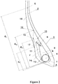
- the figure 2 illustrates in an enlarged manner a schematic cross-sectional representation of a bead 3 of the tire in which there is a part of the carcass reinforcement layer 2 wound around a bead wire 4 to form an upturn 7 with one end 8.
- the distance d E between point E and point A is equal to 128 mm.
- the distance d R between point 8 and point A is equal to 44 mm.
- the ratio of the distance d R to the distance d E is equal to 34% and therefore between 25 and 40%.
- the upturn 7 of the carcass reinforcement layer is separated from the main part of the carcass reinforcement layer 2 by a first layer of polymeric mixture 9, having a radially outer end 10 at a distance d 10 from point A equal to 105 mm.
- the first layer of polymeric mixture 9 has a modulus elasticity under tension at 10% elongation equal to 5 MPa and therefore less than the modulus of elasticity under tension at 10% elongation of the calendering layers of the carcass reinforcement 2.
- the second layer of polymeric mixture 11 Axially outside of the upturn 7 of the carcass reinforcement layer is shown the second layer of polymeric mixture 11, the radially outer end 12 of which is radially outside the end 8 of the upturn 7 of the layer d carcass reinforcement at a distance d 12 from point A equal to 112 mm.
- the radially inner end 13 of the second layer of polymeric mixture 11 is radially comprised between the points A and B, respectively radially the innermost and radially the outermost of the circle circumscribing the bead wire.
- the second layer of polymeric mixture 11 has a modulus of elasticity under tension at 10% elongation equal to 5 MPa and therefore less than the modulus of elasticity under tension at 10% elongation of the calendering layers of the reinforcement. carcass 2.
- the third layer of polymeric mixture 14 has an elastic modulus under tension at 10% elongation equal to 7.1 MPa.
- the radially inner end 17 of the fourth layer of polymeric mixture 16 is radially inner to the end 15 of the third layer of polymeric mixture 14.
- the fourth layer of polymeric mixture 16 has a modulus of elasticity under tension at 10% elongation equal to 3.1 MPa.
- the first layer of polymeric mixture 9 has a thickness E 1 , measured in the direction normal to the reinforcing elements of the main part of the carcass reinforcement layer and passing through the end of the upturn of the carcass reinforcement layer equal to 7.5 mm.
- the distance E 2 between the reinforcing elements of the main part of the carcass reinforcement layer and the outer surface of the tire measured in the direction of measurement of the thickness E 1 of the first layer of polymeric mixture passing through the end of the upturn of the carcass reinforcement layer is equal to 20 mm.
- the ratio of the thickness E 1 of the first layer 9 of polymeric mixture to the distance E 2 , measured between the reinforcing elements of the main part of the carcass reinforcement layer and the outer surface of the tire, is equal to 38% and therefore between 30 and 60%.
- the ratio of the distance E 2 , measured between the reinforcing elements of the main part of the carcass reinforcement layer and the outer surface of the tire, over the distance d R between the end of the upturn of the reinforcement layer carcass and the radially innermost point of the circle circumscribed to the bead wire is equal to 0.45 and therefore less than 0.5.
- Mixture 1 Mix 2 NR 100 100 Black N330 40 Silica 165G 45 Antioxidant 1.30 1.7 Stearic acid 0.5 1 Zinc oxide 4 4.5 sulfur 3.12 1.9 CBS accelerator 0.60 1.9 Silane on black 9 PEG4000 1 MA 10 (MPa) 3.7 5 P60 12.5 12.5 tan ( ⁇ ) max 80 ° C 0.080 0.080
- the loss factor tan ( ⁇ ) is a dynamic property of the rubber compound layer. It is measured on a viscoanalyst (Metravib VA4000), according to standard ASTM D 5992-96. The response of a sample of vulcanized composition is recorded (cylindrical test piece 2 mm thick and 78 mm 2 in section), subjected to a sinusoidal stress in alternating simple shear, at a frequency of 10 Hz, at a temperature of 80 ° C. A strain amplitude sweep is carried out from 0.1 to 50% (outward cycle), then from 50% to 1% (return cycle). The results used are the complex dynamic shear modulus (G *) and the loss factor tan ( ⁇ ) measured on the return cycle. For the return cycle, we indicate the maximum value of tan ( ⁇ ) observed, noted tan ( ⁇ ) max .
- Rolling resistance is the resistance that appears when the tire is rolling. It is represented by the hysteretic losses linked to the deformation of the tire during one revolution.
- the value of tan ( ⁇ ) at 80 ° C corresponds to an indicator of the rolling resistance of the tire when rolling.
- the tires I according to the invention are produced with first and second layers produced with the mixture 2 according to the invention.
- the reference tires R 1 differ from the tires according to the invention by the presence of stiffeners and a more usual bead area with in particular a greater bead thickness at the level of the end of the upturn of the carcass reinforcement layer and first and second layers made with mixture 1.
- the reference tires R 2 differ from the tires according to the invention only by the presence of stiffeners and a more usual bead area with in particular a greater bead thickness at the level of the end of the upturn of the carcass reinforcement layer. , the first and second layers being made with mixture 2.
- the tires R3 differ from the tires according to the invention only by having first and second layers produced with the mixture 1.
- Endurance tests were carried out by rolling two planed tires on top of each other with a regulated pressure of 8b, with nitrogen inflation and a load of 6786 daN at a speed of 30 km / h and at an ambient temperature of 15 ° C.
- the tests carried out lead, for the reference tires R, to performances establishing the base 100.
- the tests are stopped when a deterioration occurs in the bottom zone of the tire.
Landscapes
- Engineering & Computer Science (AREA)
- Mechanical Engineering (AREA)
- Tires In General (AREA)
- Compositions Of Macromolecular Compounds (AREA)
Claims (7)
- Reifen (1), welcher dazu bestimmt ist, auf einer hohlen Felge (J) vom Typ "15°-Steilschulterfelge" montiert zu werden, und welcher eine radiale Karkassenbewehrung (2) umfasst, die aus einer einzigen Karkassenbewehrungsschicht besteht, die von Verstärkungselementen gebildet wird, die zwischen zwei Kalandrierschichten aus Polymermischung eingefügt sind, wobei der Reifen (1) eine Scheitelbewehrung (5) umfasst, die ihrerseits radial von einem Laufstreifen (6) bedeckt ist, wobei der Laufstreifen über zwei Seitenwände mit zwei Wülsten (3) verbunden ist, wobei die Schicht von Verstärkungselementen der Karkassenbewehrung (2) in jedem der Wülste (3) durch Umschlag um einen Wulstkern (4) verankert ist, um einen Hauptteil der Karkassenbewehrungsschicht , der sich von einem Wulstkern (4) zum anderen erstreckt, und einen umgeschlagenen Teil (7) der Karkassenbewehrungsschicht in jedem der Wülste (3) zu bilden, wobei der umgeschlagene Teil (7) der Karkassenbewehrungsschicht vom Hauptteil der Karkassenbewehrungsschicht (2) durch eine erste Schicht aus Polymermischung (9) getrennt ist, die sich radial vom Wulstkern (4) bis wenigstens zum Ende (8) des umgeschlagenen Teils (7) der Karkassenbewehrungsschicht erstreckt, und wobei sich der umgeschlagene Teil (7) der Karkassenbewehrungsschicht axial außen mit einer zweiten Schicht aus Polymermischung (11) in Kontakt befindet, die sich ihrerseits wenigstens mit einer dritten Schicht aus Polymermischung (14) in Kontakt befindet, welche die Außenfläche des Reifens im Bereich des Wulstes (3) bildet, wobei die dritte Schicht aus Polymermischung (14) insbesondere dazu bestimmt ist, mit der Felge (J) in Kontakt zu kommen, wobei sich die dritte Schicht aus Polymermischung (14) radial außen mit einer vierten Schicht (16) in Kontakt befindet, welche die Außenfläche einer Seitenwand bildet, wobei in einem Meridianschnitt des Reifens- das radial äußere Ende (10) der ersten Schicht aus Polymermischung (9) radial außerhalb des Endes (8) des umgeschlagenen Teils (7) der Karkassenbewehrungsschicht liegt,- das radial äußere Ende (12) der zweiten Schicht aus Polymermischung (11) radial außerhalb des Endes (8) des umgeschlagenen Teils (7) der Karkassenbewehrungsschicht liegt,- die erste Schicht aus Polymermischung (9) eine Dicke E1 aufweist, gemessen in der Richtung, die zu den Verstärkungselementen des Hauptteils der Karkassenbewehrungsschicht (2) senkrecht ist und durch das Ende (8) des umgeschlagenen Teils (7) der Karkassenbewehrungsschicht verläuft, die zwischen 30 und 60 % des Abstands E2 zwischen den Verstärkungselementen des Hauptteils der Karkassenbewehrungsschicht (2) und der Außenfläche des Reifens beträgt, gemessen in der Messrichtung der Dicke E1 der ersten Schicht aus Polymermischung (9), die durch das Ende (8) des umgeschlagenen Teils (7) der Karkassenbewehrungsschicht verläuft,- das Verhältnis des Abstands E2 zwischen den Verstärkungselementen des Hauptteils der Karkassenbewehrungsschicht (2) und der Außenfläche des Reifens, gemessen in der Messrichtung der Dicke E1 der ersten Schicht aus Polymermischung (9), die durch das Ende (8) des umgeschlagenen Teils (7) der Karkassenbewehrungsschicht verläuft, zum Abstand dR zwischen dem Ende (8) des umgeschlagenen Teils (7) der Karkassenbewehrungsschicht und dem radial innersten Punkt (A) des dem Wulstkern (4) umbeschriebenen Kreises (T) kleiner als 0,5 ist,- der umgeschlagene Teil (7) der Karkassenbewehrungsschicht und der Hauptteil der Karkassenbewehrungsschicht (2) die einzigen Schichten von Verstärkungselementen, deren Bruchdehnung kleiner als 6 % ist, sind, die in einem Bereich der Seitenwand vorhanden sind, der wenigstens 90 % der Fläche bildet, die radial zwischen dem Ende (8) des umgeschlagenen Teils (7) der Karkassenbewehrungsschicht und dem radial äußersten Punkt (B) des Wulstkerns (4) liegt,dadurch gekennzeichnet, dass in einem Meridianschnitt des Reifens- der Abstand dR zwischen dem Ende (8) des umgeschlagenen Teils (7) der Karkassenbewehrungsschicht und dem radial innersten Punkt (A) des dem Wulstkern (4) umbeschriebenen Kreises (T) zwischen 25 und 40 % des Abstands dE zwischen dem axial äußersten Punkt (E) des Hauptteils der Karkassenbewehrungsschicht (2) und dem radial innersten Punkt (A) des dem Wulstkern (4) umbeschriebenen Kreises (T) beträgt,- die erste und die zweite Schicht aus Polymermischung (9, 11) einen verstärkenden Füllstoff aufweisen, der aus wenigstens einem hellen Füllstoff vom Typ Kieselsäure und/oder Aluminiumoxid besteht, der Oberflächengruppen SiOH und/oder AlOH aufweist und aus der Gruppe ausgewählt ist, die von den gefällten oder pyrogenen Kieselsäuren, den Aluminiumoxiden oder den Aluminiumsilikaten oder auch den während oder nach der Synthese modifizierten Rußen gebildet wird,- die Elastizitätsmodule unter Spannung bei 10 % Dehnung der ersten und der zweiten Schicht aus Polymermischung (9, 11) kleiner als der Elastizitätsmodul unter Spannung bei 10 % Dehnung der Kalandrierung der Karkassenbewehrungsschicht (2) und größer oder gleich 30 % des Elastizitätsmoduls unter Spannung bei 10 % Dehnung der Kalandrierung der Karkassenbewehrungsschicht (2) sind, wobei die Messungen der Module im Zugversuch gemäß der Norm AFNOR-NFT-46002 vom September 1988 und unter Normbedingungen für Temperatur und Feuchtigkeit gemäß der Norm AFNOR-NFT-40101 vom Dezember 1979 durchgeführt werden.
- Reifen (1) nach Anspruch 1, dadurch gekennzeichnet, dass die erste und die zweite Schicht aus Polymermischung (9, 11) Elastomermischungen auf der Basis von Naturkautschuk oder von synthetischem Polyisopren mit einer Mehrheit von cis-1,4-Verkettungen und eventuell von wenigstens einem weiteren Dienelastomer sind, wobei der Naturkautschuk oder das synthetische Polyisopren im Falle eines Verschnitts in einem Mehrheitsanteil in Bezug auf den Anteil des anderen oder der anderen verwendeten Dienelastomere vorhanden ist, und von einem verstärkenden Füllstoff, welcher besteht:a) entweder aus einem hellen Füllstoff vom Typ Kieselsäure und/oder Aluminiumoxid, der Oberflächengruppen SiOH und/oder AlOH aufweist und aus der Gruppe ausgewählt ist, die von den gefällten oder pyrogenen Kieselsäuren, den Aluminiumoxiden oder den Aluminiumsilikaten oder auch den während oder nach der Synthese modifizierten Rußen mit einer spezifischen BET-Oberfläche zwischen 30 und 260 m2/g gebildet wird, verwendet in einem Anteil zwischen 20 und 80 pce und vorzugsweise zwischen 30 und 50 pce, wobei die Messung der spezifischen BET-Oberfläche gemäß dem Verfahren von BRUNAUER, EMMET und TELLER durchgeführt wird, das in "The Journal of the American Chemical Society", Bd. 60, Seite 309, Februar 1938, beschrieben ist, das der Norm NFT 45007 vom November 1987 entspricht;b) oder aus einem Verschnitt eines in (a) beschriebenen hellen Füllstoffs und von Ruß, wobei der Gesamtanteil von Füllstoff zwischen 20 und 80 pce und vorzugsweise zwischen 40 und 60 pce liegt, wobei der Anteil von Kieselsäure am Gesamtanteil von Füllstoff größer als 80 % und vorzugsweise größer als 90 % ist.
- Reifen (1) nach einem der Ansprüche 1 oder 2, dadurch gekennzeichnet, dass der Elastizitätsmodul unter Spannung bei 10 % Dehnung der Kalandrierschichten der Karkassenbewehrungsschicht (2) zwischen 4 und 16 MPa und vorzugsweise zwischen 8 und 12 MPa liegt.
- Reifen (1) nach einem der vorhergehenden Ansprüche, dadurch gekennzeichnet, dass das radial innere Ende (13) der zweiten Schicht aus Polymermischung (11) radial zwischen dem radial äußersten Punkt (B) des dem Wulstkern (4) umbeschriebenen Kreises (T) und dem radial innersten Punkt (A) des dem Wulstkern (4) umbeschriebenen Kreises (T) liegt.
- Reifen (1) nach einem der vorhergehenden Ansprüche, dadurch gekennzeichnet, dass der Abstand dR zwischen dem Ende (8) des umgeschlagenen Teils (7) der Karkassenbewehrungsschicht und dem radial innersten Punkt (A) des dem Wulstkern (4) umbeschriebenen Kreises (T) zwischen 31 und 37 % des Abstands dE zwischen dem axial äußersten Punkt (E) des Hauptteils der Karkassenbewehrungsschicht (2) und dem radial innersten Punkt (A) des dem Wulstkern (4) umbeschriebenen Kreises (T) beträgt.
- Reifen (1) nach einem der vorhergehenden Ansprüche, dadurch gekennzeichnet, dass in jeder Meridianebene, in jedem Wulst (3), der Reifen eine Fixierungsbewehrung, die den Wulstkern (4) umgibt, und ein Volumen von Kautschukmischung, das sich mit dem Wulstkern (4) direkt in Kontakt befindet, aufweist.
- Reifen (1) nach einem der vorhergehenden Ansprüche, dadurch gekennzeichnet, dass die Wulstkerne (4) Wulstkernpakete sind, vorzugsweise von sechseckiger Form.
Applications Claiming Priority (2)
| Application Number | Priority Date | Filing Date | Title |
|---|---|---|---|
| FR1656721A FR3053931B1 (fr) | 2016-07-13 | 2016-07-13 | Pneumatique dont la zone du bourrelet est allegee |
| PCT/FR2017/051898 WO2018011515A1 (fr) | 2016-07-13 | 2017-07-11 | Pneumatique dont la zone du bourrelet est allégée |
Publications (2)
| Publication Number | Publication Date |
|---|---|
| EP3484729A1 EP3484729A1 (de) | 2019-05-22 |
| EP3484729B1 true EP3484729B1 (de) | 2020-09-02 |
Family
ID=56920817
Family Applications (1)
| Application Number | Title | Priority Date | Filing Date |
|---|---|---|---|
| EP17748536.4A Not-in-force EP3484729B1 (de) | 2016-07-13 | 2017-07-11 | Reifen mit wulstbereich mit reduziertem gewicht |
Country Status (5)
| Country | Link |
|---|---|
| EP (1) | EP3484729B1 (de) |
| CN (1) | CN109476190B (de) |
| CA (1) | CA3029972A1 (de) |
| FR (1) | FR3053931B1 (de) |
| WO (1) | WO2018011515A1 (de) |
Families Citing this family (2)
| Publication number | Priority date | Publication date | Assignee | Title |
|---|---|---|---|---|
| JP7059746B2 (ja) * | 2018-03-27 | 2022-04-26 | 住友ゴム工業株式会社 | 空気入りタイヤ |
| KR102204855B1 (ko) | 2019-04-16 | 2021-01-20 | 한국타이어앤테크놀로지 주식회사 | 다중고무층이 적용된 비드필러를 구비한 공기입 타이어 |
Family Cites Families (14)
| Publication number | Priority date | Publication date | Assignee | Title |
|---|---|---|---|---|
| US6323273B1 (en) | 1995-05-22 | 2001-11-27 | Cabot Corporation | Elastomeric compounds incorporating silicon-treated carbon blacks |
| US5883179A (en) | 1995-10-25 | 1999-03-16 | The Yokohama Rubber Co., Ltd. | Rubber composition comprising carbon black surface treated with silica |
| US6197274B1 (en) | 1996-09-25 | 2001-03-06 | Cabot Corporation | Silica coated carbon blacks |
| EP0884200B1 (de) * | 1997-06-12 | 2003-11-05 | Bridgestone Corporation | Radiale LKW-Reifen |
| JPH11170823A (ja) * | 1997-12-16 | 1999-06-29 | Bridgestone Corp | 重荷重用空気入りラジアルタイヤ |
| FR2779387B1 (fr) | 1998-06-05 | 2000-08-11 | Michelin & Cie | Bourrelet renforce de pneumatique radial |
| FR2787744A1 (fr) * | 1998-12-24 | 2000-06-30 | Michelin Soc Tech | Bourrelet de pneumatique radial |
| WO2004033789A1 (fr) | 2002-10-11 | 2004-04-22 | Societe De Technologie Michelin | Cables utilisables pour renforcer des pneumatiques poids-lourd |
| JP2010132218A (ja) * | 2008-12-08 | 2010-06-17 | Yokohama Rubber Co Ltd:The | 空気入りラジアルタイヤ |
| EP2465710B1 (de) * | 2009-09-16 | 2014-06-25 | Bridgestone Corporation | Radialluftreifen |
| FR2952589B1 (fr) * | 2009-11-13 | 2011-11-11 | Michelin Soc Tech | Bourrelet de pneu pour vehicule petit poids lourd. |
| FR2976221B1 (fr) * | 2011-06-07 | 2014-01-03 | Michelin Soc Tech | Bourrelet de pneumatique pour vehicule lourd de type genie civil |
| FR2989032B1 (fr) * | 2012-04-05 | 2015-04-10 | Michelin & Cie | Pneumatique et ensemble pneumatique-roue a mobilite etendue |
| US20150107746A1 (en) * | 2013-10-18 | 2015-04-23 | E I Du Pont De Nemours And Company | Tire apex structure |
-
2016
- 2016-07-13 FR FR1656721A patent/FR3053931B1/fr active Active
-
2017
- 2017-07-11 CN CN201780042895.7A patent/CN109476190B/zh not_active Expired - Fee Related
- 2017-07-11 EP EP17748536.4A patent/EP3484729B1/de not_active Not-in-force
- 2017-07-11 WO PCT/FR2017/051898 patent/WO2018011515A1/fr not_active Ceased
- 2017-07-11 CA CA3029972A patent/CA3029972A1/fr not_active Abandoned
Non-Patent Citations (1)
| Title |
|---|
| None * |
Also Published As
| Publication number | Publication date |
|---|---|
| CA3029972A1 (fr) | 2018-01-18 |
| CN109476190A (zh) | 2019-03-15 |
| WO2018011515A1 (fr) | 2018-01-18 |
| CN109476190B (zh) | 2020-06-16 |
| FR3053931A1 (fr) | 2018-01-19 |
| FR3053931B1 (fr) | 2018-07-13 |
| EP3484729A1 (de) | 2019-05-22 |
Similar Documents
| Publication | Publication Date | Title |
|---|---|---|
| EP4323201B1 (de) | Leichtgewichtreifen mit einer lage aus umfangsverstärkungselementen | |
| EP3390101B1 (de) | Reifen mit verbesserten abnutzungs- und rollwiderstandseigenschaften | |
| WO2019048762A1 (fr) | Pneumatique allege | |
| EP3484725A1 (de) | Reifen mit gewichtsreduziertem wulstbereich | |
| EP3390089B1 (de) | Reifen mit verbesserten eigenschaften der abnutzung und des rollwiderstands | |
| EP3484729B1 (de) | Reifen mit wulstbereich mit reduziertem gewicht | |
| EP3390084B1 (de) | Reifen mit verbesserten abnutzungs- und rollwiderstandseigenschaften | |
| WO2019106248A1 (fr) | Pneumatique dont la zone du bourrelet est allegee | |
| EP3390099B1 (de) | Reifen mit verbesserten eigenschaften der abriebfestigkeit und des rollwiderstands | |
| EP3390100B1 (de) | Reifen mit verbesserten eigenschaften der abnutzung und des rollwiderstands | |
| EP3390080B1 (de) | Reifen mit verbesserten abnutzungs- und rollwiderstandseigenschaften | |
| WO2019063918A1 (fr) | Pneumatique allege | |
| EP3390083B1 (de) | Reifen mit verbesserten abnutzungs- und rollwiderstandseigenschaften | |
| EP3390086B1 (de) | Reifen mit verbesserten abnutzungs- und rollwiderstandseigenschaften | |
| EP3390082B1 (de) | Reifen mit verbesserten abnutzungseigenschaften und verbessertem rollwiderstand | |
| EP3390081B1 (de) | Reifen mit verbesserten abnutzungs- und rollwiderstandseigenschaften | |
| EP3390095B1 (de) | Reifen mit verbesserten abnutzungs- und rollwiderstandseigenschaften | |
| EP3390104B1 (de) | Reifen mit verbesserten abnutzungs- und rollwiderstandseigenschaften | |
| EP3390103B1 (de) | Reifen mit verbesserten abnutzungseigenschaften und verbessertem rollwiderstand | |
| EP3390102B1 (de) | Reifen mit verbesserten abnutzungs- und rollwiderstandseigenschaften | |
| EP3390098B1 (de) | Reifen mit verbesserten eigenschaften der abnutzung und des rollwiderstands | |
| EP3390096B1 (de) | Reifen mit verbesserten verschleisseigenschaften und verbessertem rollwiderstand | |
| EP4323202B1 (de) | Leichtgewichtreifen mit einer lage aus umfangsverstärkungselementen | |
| WO2019048760A1 (fr) | Pneumatique allege | |
| EP3390088B1 (de) | Reifen mit verbesserten abnutzungs- und rollwiderstandseigenschaften |
Legal Events
| Date | Code | Title | Description |
|---|---|---|---|
| STAA | Information on the status of an ep patent application or granted ep patent |
Free format text: STATUS: UNKNOWN |
|
| STAA | Information on the status of an ep patent application or granted ep patent |
Free format text: STATUS: THE INTERNATIONAL PUBLICATION HAS BEEN MADE |
|
| PUAI | Public reference made under article 153(3) epc to a published international application that has entered the european phase |
Free format text: ORIGINAL CODE: 0009012 |
|
| STAA | Information on the status of an ep patent application or granted ep patent |
Free format text: STATUS: REQUEST FOR EXAMINATION WAS MADE |
|
| 17P | Request for examination filed |
Effective date: 20190213 |
|
| AK | Designated contracting states |
Kind code of ref document: A1 Designated state(s): AL AT BE BG CH CY CZ DE DK EE ES FI FR GB GR HR HU IE IS IT LI LT LU LV MC MK MT NL NO PL PT RO RS SE SI SK SM TR |
|
| AX | Request for extension of the european patent |
Extension state: BA ME |
|
| DAV | Request for validation of the european patent (deleted) | ||
| DAX | Request for extension of the european patent (deleted) | ||
| GRAP | Despatch of communication of intention to grant a patent |
Free format text: ORIGINAL CODE: EPIDOSNIGR1 |
|
| STAA | Information on the status of an ep patent application or granted ep patent |
Free format text: STATUS: GRANT OF PATENT IS INTENDED |
|
| INTG | Intention to grant announced |
Effective date: 20200331 |
|
| GRAS | Grant fee paid |
Free format text: ORIGINAL CODE: EPIDOSNIGR3 |
|
| GRAA | (expected) grant |
Free format text: ORIGINAL CODE: 0009210 |
|
| STAA | Information on the status of an ep patent application or granted ep patent |
Free format text: STATUS: THE PATENT HAS BEEN GRANTED |
|
| AK | Designated contracting states |
Kind code of ref document: B1 Designated state(s): AL AT BE BG CH CY CZ DE DK EE ES FI FR GB GR HR HU IE IS IT LI LT LU LV MC MK MT NL NO PL PT RO RS SE SI SK SM TR |
|
| REG | Reference to a national code |
Ref country code: GB Ref legal event code: FG4D Free format text: NOT ENGLISH |
|
| REG | Reference to a national code |
Ref country code: AT Ref legal event code: REF Ref document number: 1308427 Country of ref document: AT Kind code of ref document: T Effective date: 20200915 Ref country code: CH Ref legal event code: EP |
|
| REG | Reference to a national code |
Ref country code: DE Ref legal event code: R096 Ref document number: 602017022867 Country of ref document: DE |
|
| REG | Reference to a national code |
Ref country code: IE Ref legal event code: FG4D Free format text: LANGUAGE OF EP DOCUMENT: FRENCH |
|
| REG | Reference to a national code |
Ref country code: LT Ref legal event code: MG4D |
|
| PG25 | Lapsed in a contracting state [announced via postgrant information from national office to epo] |
Ref country code: FI Free format text: LAPSE BECAUSE OF FAILURE TO SUBMIT A TRANSLATION OF THE DESCRIPTION OR TO PAY THE FEE WITHIN THE PRESCRIBED TIME-LIMIT Effective date: 20200902 Ref country code: GR Free format text: LAPSE BECAUSE OF FAILURE TO SUBMIT A TRANSLATION OF THE DESCRIPTION OR TO PAY THE FEE WITHIN THE PRESCRIBED TIME-LIMIT Effective date: 20201203 Ref country code: NO Free format text: LAPSE BECAUSE OF FAILURE TO SUBMIT A TRANSLATION OF THE DESCRIPTION OR TO PAY THE FEE WITHIN THE PRESCRIBED TIME-LIMIT Effective date: 20201202 Ref country code: BG Free format text: LAPSE BECAUSE OF FAILURE TO SUBMIT A TRANSLATION OF THE DESCRIPTION OR TO PAY THE FEE WITHIN THE PRESCRIBED TIME-LIMIT Effective date: 20201202 Ref country code: SE Free format text: LAPSE BECAUSE OF FAILURE TO SUBMIT A TRANSLATION OF THE DESCRIPTION OR TO PAY THE FEE WITHIN THE PRESCRIBED TIME-LIMIT Effective date: 20200902 Ref country code: HR Free format text: LAPSE BECAUSE OF FAILURE TO SUBMIT A TRANSLATION OF THE DESCRIPTION OR TO PAY THE FEE WITHIN THE PRESCRIBED TIME-LIMIT Effective date: 20200902 Ref country code: LT Free format text: LAPSE BECAUSE OF FAILURE TO SUBMIT A TRANSLATION OF THE DESCRIPTION OR TO PAY THE FEE WITHIN THE PRESCRIBED TIME-LIMIT Effective date: 20200902 |
|
| REG | Reference to a national code |
Ref country code: NL Ref legal event code: MP Effective date: 20200902 |
|
| REG | Reference to a national code |
Ref country code: AT Ref legal event code: MK05 Ref document number: 1308427 Country of ref document: AT Kind code of ref document: T Effective date: 20200902 |
|
| PG25 | Lapsed in a contracting state [announced via postgrant information from national office to epo] |
Ref country code: LV Free format text: LAPSE BECAUSE OF FAILURE TO SUBMIT A TRANSLATION OF THE DESCRIPTION OR TO PAY THE FEE WITHIN THE PRESCRIBED TIME-LIMIT Effective date: 20200902 Ref country code: PL Free format text: LAPSE BECAUSE OF FAILURE TO SUBMIT A TRANSLATION OF THE DESCRIPTION OR TO PAY THE FEE WITHIN THE PRESCRIBED TIME-LIMIT Effective date: 20200902 Ref country code: RS Free format text: LAPSE BECAUSE OF FAILURE TO SUBMIT A TRANSLATION OF THE DESCRIPTION OR TO PAY THE FEE WITHIN THE PRESCRIBED TIME-LIMIT Effective date: 20200902 |
|
| PG25 | Lapsed in a contracting state [announced via postgrant information from national office to epo] |
Ref country code: SM Free format text: LAPSE BECAUSE OF FAILURE TO SUBMIT A TRANSLATION OF THE DESCRIPTION OR TO PAY THE FEE WITHIN THE PRESCRIBED TIME-LIMIT Effective date: 20200902 Ref country code: EE Free format text: LAPSE BECAUSE OF FAILURE TO SUBMIT A TRANSLATION OF THE DESCRIPTION OR TO PAY THE FEE WITHIN THE PRESCRIBED TIME-LIMIT Effective date: 20200902 Ref country code: RO Free format text: LAPSE BECAUSE OF FAILURE TO SUBMIT A TRANSLATION OF THE DESCRIPTION OR TO PAY THE FEE WITHIN THE PRESCRIBED TIME-LIMIT Effective date: 20200902 Ref country code: PT Free format text: LAPSE BECAUSE OF FAILURE TO SUBMIT A TRANSLATION OF THE DESCRIPTION OR TO PAY THE FEE WITHIN THE PRESCRIBED TIME-LIMIT Effective date: 20210104 Ref country code: CZ Free format text: LAPSE BECAUSE OF FAILURE TO SUBMIT A TRANSLATION OF THE DESCRIPTION OR TO PAY THE FEE WITHIN THE PRESCRIBED TIME-LIMIT Effective date: 20200902 |
|
| PG25 | Lapsed in a contracting state [announced via postgrant information from national office to epo] |
Ref country code: IS Free format text: LAPSE BECAUSE OF FAILURE TO SUBMIT A TRANSLATION OF THE DESCRIPTION OR TO PAY THE FEE WITHIN THE PRESCRIBED TIME-LIMIT Effective date: 20210102 Ref country code: ES Free format text: LAPSE BECAUSE OF FAILURE TO SUBMIT A TRANSLATION OF THE DESCRIPTION OR TO PAY THE FEE WITHIN THE PRESCRIBED TIME-LIMIT Effective date: 20200902 Ref country code: AT Free format text: LAPSE BECAUSE OF FAILURE TO SUBMIT A TRANSLATION OF THE DESCRIPTION OR TO PAY THE FEE WITHIN THE PRESCRIBED TIME-LIMIT Effective date: 20200902 Ref country code: AL Free format text: LAPSE BECAUSE OF FAILURE TO SUBMIT A TRANSLATION OF THE DESCRIPTION OR TO PAY THE FEE WITHIN THE PRESCRIBED TIME-LIMIT Effective date: 20200902 |
|
| REG | Reference to a national code |
Ref country code: DE Ref legal event code: R097 Ref document number: 602017022867 Country of ref document: DE |
|
| PG25 | Lapsed in a contracting state [announced via postgrant information from national office to epo] |
Ref country code: SK Free format text: LAPSE BECAUSE OF FAILURE TO SUBMIT A TRANSLATION OF THE DESCRIPTION OR TO PAY THE FEE WITHIN THE PRESCRIBED TIME-LIMIT Effective date: 20200902 |
|
| PLBE | No opposition filed within time limit |
Free format text: ORIGINAL CODE: 0009261 |
|
| STAA | Information on the status of an ep patent application or granted ep patent |
Free format text: STATUS: NO OPPOSITION FILED WITHIN TIME LIMIT |
|
| 26N | No opposition filed |
Effective date: 20210603 |
|
| PG25 | Lapsed in a contracting state [announced via postgrant information from national office to epo] |
Ref country code: DK Free format text: LAPSE BECAUSE OF FAILURE TO SUBMIT A TRANSLATION OF THE DESCRIPTION OR TO PAY THE FEE WITHIN THE PRESCRIBED TIME-LIMIT Effective date: 20200902 Ref country code: SI Free format text: LAPSE BECAUSE OF FAILURE TO SUBMIT A TRANSLATION OF THE DESCRIPTION OR TO PAY THE FEE WITHIN THE PRESCRIBED TIME-LIMIT Effective date: 20200902 |
|
| PG25 | Lapsed in a contracting state [announced via postgrant information from national office to epo] |
Ref country code: IT Free format text: LAPSE BECAUSE OF FAILURE TO SUBMIT A TRANSLATION OF THE DESCRIPTION OR TO PAY THE FEE WITHIN THE PRESCRIBED TIME-LIMIT Effective date: 20200902 |
|
| REG | Reference to a national code |
Ref country code: CH Ref legal event code: PL |
|
| GBPC | Gb: european patent ceased through non-payment of renewal fee |
Effective date: 20210711 |
|
| PG25 | Lapsed in a contracting state [announced via postgrant information from national office to epo] |
Ref country code: MC Free format text: LAPSE BECAUSE OF FAILURE TO SUBMIT A TRANSLATION OF THE DESCRIPTION OR TO PAY THE FEE WITHIN THE PRESCRIBED TIME-LIMIT Effective date: 20200902 |
|
| REG | Reference to a national code |
Ref country code: BE Ref legal event code: MM Effective date: 20210731 |
|
| PG25 | Lapsed in a contracting state [announced via postgrant information from national office to epo] |
Ref country code: LI Free format text: LAPSE BECAUSE OF NON-PAYMENT OF DUE FEES Effective date: 20210731 Ref country code: GB Free format text: LAPSE BECAUSE OF NON-PAYMENT OF DUE FEES Effective date: 20210711 Ref country code: CH Free format text: LAPSE BECAUSE OF NON-PAYMENT OF DUE FEES Effective date: 20210731 |
|
| PG25 | Lapsed in a contracting state [announced via postgrant information from national office to epo] |
Ref country code: LU Free format text: LAPSE BECAUSE OF NON-PAYMENT OF DUE FEES Effective date: 20210711 |
|
| PG25 | Lapsed in a contracting state [announced via postgrant information from national office to epo] |
Ref country code: IE Free format text: LAPSE BECAUSE OF NON-PAYMENT OF DUE FEES Effective date: 20210711 Ref country code: BE Free format text: LAPSE BECAUSE OF NON-PAYMENT OF DUE FEES Effective date: 20210731 |
|
| PGFP | Annual fee paid to national office [announced via postgrant information from national office to epo] |
Ref country code: DE Payment date: 20220720 Year of fee payment: 6 |
|
| PGFP | Annual fee paid to national office [announced via postgrant information from national office to epo] |
Ref country code: FR Payment date: 20220720 Year of fee payment: 6 |
|
| PG25 | Lapsed in a contracting state [announced via postgrant information from national office to epo] |
Ref country code: NL Free format text: LAPSE BECAUSE OF NON-PAYMENT OF DUE FEES Effective date: 20200923 Ref country code: CY Free format text: LAPSE BECAUSE OF FAILURE TO SUBMIT A TRANSLATION OF THE DESCRIPTION OR TO PAY THE FEE WITHIN THE PRESCRIBED TIME-LIMIT Effective date: 20200902 |
|
| PG25 | Lapsed in a contracting state [announced via postgrant information from national office to epo] |
Ref country code: HU Free format text: LAPSE BECAUSE OF FAILURE TO SUBMIT A TRANSLATION OF THE DESCRIPTION OR TO PAY THE FEE WITHIN THE PRESCRIBED TIME-LIMIT; INVALID AB INITIO Effective date: 20170711 |
|
| REG | Reference to a national code |
Ref country code: DE Ref legal event code: R119 Ref document number: 602017022867 Country of ref document: DE |
|
| PG25 | Lapsed in a contracting state [announced via postgrant information from national office to epo] |
Ref country code: MK Free format text: LAPSE BECAUSE OF FAILURE TO SUBMIT A TRANSLATION OF THE DESCRIPTION OR TO PAY THE FEE WITHIN THE PRESCRIBED TIME-LIMIT Effective date: 20200902 Ref country code: DE Free format text: LAPSE BECAUSE OF NON-PAYMENT OF DUE FEES Effective date: 20240201 |
|
| PG25 | Lapsed in a contracting state [announced via postgrant information from national office to epo] |
Ref country code: FR Free format text: LAPSE BECAUSE OF NON-PAYMENT OF DUE FEES Effective date: 20230731 |
|
| PG25 | Lapsed in a contracting state [announced via postgrant information from national office to epo] |
Ref country code: MT Free format text: LAPSE BECAUSE OF FAILURE TO SUBMIT A TRANSLATION OF THE DESCRIPTION OR TO PAY THE FEE WITHIN THE PRESCRIBED TIME-LIMIT Effective date: 20200902 |
|
| PG25 | Lapsed in a contracting state [announced via postgrant information from national office to epo] |
Ref country code: TR Free format text: LAPSE BECAUSE OF FAILURE TO SUBMIT A TRANSLATION OF THE DESCRIPTION OR TO PAY THE FEE WITHIN THE PRESCRIBED TIME-LIMIT Effective date: 20200902 |