EP3484431B1 - Zubehörteil mit klemmbefestigung - Google Patents
Zubehörteil mit klemmbefestigung Download PDFInfo
- Publication number
- EP3484431B1 EP3484431B1 EP17737760.3A EP17737760A EP3484431B1 EP 3484431 B1 EP3484431 B1 EP 3484431B1 EP 17737760 A EP17737760 A EP 17737760A EP 3484431 B1 EP3484431 B1 EP 3484431B1
- Authority
- EP
- European Patent Office
- Prior art keywords
- plate
- accessory
- clamping
- relative
- clamping surface
- Prior art date
- Legal status (The legal status is an assumption and is not a legal conclusion. Google has not performed a legal analysis and makes no representation as to the accuracy of the status listed.)
- Active
Links
Images



Classifications
-
- A—HUMAN NECESSITIES
- A61—MEDICAL OR VETERINARY SCIENCE; HYGIENE
- A61G—TRANSPORT, PERSONAL CONVEYANCES, OR ACCOMMODATION SPECIALLY ADAPTED FOR PATIENTS OR DISABLED PERSONS; OPERATING TABLES OR CHAIRS; CHAIRS FOR DENTISTRY; FUNERAL DEVICES
- A61G13/00—Operating tables; Auxiliary appliances therefor
- A61G13/10—Parts, details or accessories
- A61G13/101—Clamping means for connecting accessories to the operating table
-
- A—HUMAN NECESSITIES
- A61—MEDICAL OR VETERINARY SCIENCE; HYGIENE
- A61G—TRANSPORT, PERSONAL CONVEYANCES, OR ACCOMMODATION SPECIALLY ADAPTED FOR PATIENTS OR DISABLED PERSONS; OPERATING TABLES OR CHAIRS; CHAIRS FOR DENTISTRY; FUNERAL DEVICES
- A61G13/00—Operating tables; Auxiliary appliances therefor
- A61G13/10—Parts, details or accessories
- A61G13/12—Rests specially adapted therefor; Arrangements of patient-supporting surfaces
-
- A—HUMAN NECESSITIES
- A61—MEDICAL OR VETERINARY SCIENCE; HYGIENE
- A61G—TRANSPORT, PERSONAL CONVEYANCES, OR ACCOMMODATION SPECIALLY ADAPTED FOR PATIENTS OR DISABLED PERSONS; OPERATING TABLES OR CHAIRS; CHAIRS FOR DENTISTRY; FUNERAL DEVICES
- A61G13/00—Operating tables; Auxiliary appliances therefor
- A61G13/10—Parts, details or accessories
- A61G13/12—Rests specially adapted therefor; Arrangements of patient-supporting surfaces
- A61G13/1205—Rests specially adapted therefor; Arrangements of patient-supporting surfaces for specific parts of the body
- A61G13/121—Head or neck
-
- A—HUMAN NECESSITIES
- A61—MEDICAL OR VETERINARY SCIENCE; HYGIENE
- A61G—TRANSPORT, PERSONAL CONVEYANCES, OR ACCOMMODATION SPECIALLY ADAPTED FOR PATIENTS OR DISABLED PERSONS; OPERATING TABLES OR CHAIRS; CHAIRS FOR DENTISTRY; FUNERAL DEVICES
- A61G2210/00—Devices for specific treatment or diagnosis
- A61G2210/50—Devices for specific treatment or diagnosis for radiography
Definitions
- the present invention relates to an accessory, such as a head plate, for a medical device, such as an operating table or a transfer board.
- the present invention relates to an accessory that is suitable for imaging body parts of a patient supported on the accessory using imaging methods such as x-rays, computed tomography (CT), angiography or magnetic resonance imaging (MRI).
- imaging methods such as x-rays, computed tomography (CT), angiography or magnetic resonance imaging (MRI).
- Conventional head plates or leg plates usually have struts and fastening mechanisms which can show up as artefacts in an x-ray image of a patient's body part lying on the plate. Furthermore, the position of conventional head or leg plates is often not infinitely adjustable, so that intraoperative fine adjustment of the head plate can be difficult. With other accessories, such as leg plates, it may also be desirable to adjust the position of each patient to suit different sizes.
- head and leg plates With conventional head and leg plates, it is difficult to remove, assemble, or replace the plates while a patient is lying on the transfer board or operating table without lifting the patient.
- head or leg plates are attached to medical devices with trunnion interfaces, which are made of metal and are therefore non-transmissible.
- the WO 2015/081452 A1 describes a transfer device for a therapy couch.
- the above-mentioned object is achieved by an accessory for a medical device, in particular for an operating table or for a transfer board, having the features of claim 1.
- the accessory comprises a first plate for supporting a body part of a patient, and a second plate which is movable relative to the first plate in a predetermined adjustment range, a first clamping surface, and a second clamping surface spaced from the first clamping surface, the first clamping surface being on the first plate is arranged and the second clamping surface is arranged on the second plate.
- the second plate does not necessarily have to have the same shape and/or dimensions as the first plate, but that the second plate can also be significantly narrower, or can be designed as a structure of one or more struts or the like. Movement of the second plate relative to the first plate causes movement of the second clamping surface relative to the first clamping surface in a direction substantially parallel to a surface of the first or second plate to apply a clamping force between the accessory and a suitable mount on the medical device increase or decrease. The accessory can thus be securely fastened to the medical device by means of a scissor clamp.
- the movement of the second plate relative to the first plate can be a rotational movement.
- the second plate can be displaced relative to the first plate, or that a combined rotation and displacement of the second plate is carried out relative to the first plate.
- the first and the second plate are arranged one above the other.
- a structurally simple construction is thereby made possible in a particularly simple manner.
- a bearing surface may be provided between the first and second plates, the bearing surface having a diameter that is smaller than a width dimension of the first or second plate.
- About the bearing surface can be a low-friction Rotational movement of the second can be achieved relative to the first plate about a defined axis of rotation.
- the rotation of the second plate relative to the first plate can take place about an axis of rotation running through the bearing surface.
- a bearing disk can be arranged between the first and the second plate, which forms at least part of the bearing surface.
- the use of a bearing washer is only optional, i.e. the bearing washer can also be left out.
- the first clamping surface is arranged on the first plate and the second clamping surface is arranged on the second plate.
- a distance between the two clamping surfaces can thus be adjusted by moving the two plates relative to one another in order to vary a clamping force.
- the accessory may include a third clamping surface on the first plate and a fourth clamping surface on the second plate, wherein movement of the second plate relative to the first plate moves the third clamping surface relative to the fourth clamping surface. In this way, a particularly secure clamping can be achieved using the four clamping surfaces.
- a movement of the second plate relative to the first plate can cause the first and the fourth clamping surface to contact a first side of the holder on the medical device and the second and/or the third clamping surface to contact a second side of the holder.
- an accessory can be provided, with the first plate having an insertion area that can be inserted into a suitable holder on the medical device.
- the tray may also include a support area on which the patient's body part may be supported, or the patient's body part may be arranged to be supported on the same portion of the tray that also serves as the slide-in area.
- the accessory can Include clamping device for attaching the accessory to the medical device, wherein the clamping device comprises at least one clamping element which is rotatably connected to the first plate, and wherein for attaching the accessory to the medical device, the at least one clamping element is rotated relative to the first plate.
- a scissor-like clamping is achieved, whereby the clamping element on the one hand and the plate on the other hand can be spread apart by the rotation and a clamping force can be exerted on a surrounding surface, such as a receiving groove of the medical device.
- the scissors-like clamp allows the accessory to be positioned securely and steplessly on the medical device. Both a surface of the first plate or a surface of a projection formed on the first plate and a surface of the clamping element or a projection formed on the second plate are each pressed against suitable surfaces of the medical device.
- the two plates or the clamping device can be designed in such a way that they can be pushed into a receiving groove on the medical device.
- the twisting of the at least one clamping element or the second plate relative to the first plate can cause the accessory to be jammed in the receiving groove.
- the plate and the clamping device can also be designed in such a way that they are clamped, for example, between two suitable struts of the medical device without a receiving groove necessarily having to be present.
- the first and/or the second plate can each comprise at least one clamping projection which is arranged on at least one corner of the insertion area. It can thus also be ensured by the shape of the first or second plate that the insertion area is clamped to the medical device in each case at the corner areas.
- the at least one clamping projection of the first and/or the second plate can have an essentially wedge-shaped cross section, wherein the at least one clamping projection of the first and/or second plate can have two friction surfaces for contacting the medical device.
- the first and the second plate can thus have an essentially wedge-shaped cross section in the area of the respective clamping surfaces, with each wedge having two friction surfaces for contacting the medical device.
- the clamping device can comprise an actuating lever which causes the second plate or the clamping element to rotate relative to the first plate via an actuating mechanism. A user can thus easily release or fix the deadlock using the actuating lever.
- the actuating lever can be rotatably attached to the first or the second plate.
- the actuating lever may have a groove or slot which engages a pin attached to either the second or first plate.
- the cam track can be formed by the groove or slot on the operating lever, and the cam can be formed by the pin on the second plate.
- An eccentric mechanism can thus be implemented, via which the first and the second plate can be rotated in relation to one another.
- the cam can also be formed on the actuating lever and the cam disk, which defines the cam track by means of a groove or slot, can be formed on the clamping element or on the first plate.
- the groove or the slot in the actuating lever can be shaped in such a way that an actuating force or an actuating moment when the actuating lever is actuated to rotate the second plate relative to the first plate initially increases, then reaches a maximum value and then falls again before the clamping position of the accessory is reached value falls below the maximum value.
- An edge or an edge surface of the groove or the slit may be elastically deformable, so that the groove or the slit can be elastically deformed during the operation of the operating lever by the pin.
- manufacturing tolerances can be compensated for by deforming the groove.
- one or more slot-shaped recesses can be provided in the actuating lever, which essentially run parallel to an edge of the groove.
- other elastic elements can be used in the power flow to compensate for manufacturing tolerances.
- the optional bearing washer between the two plates can be made of elastic material.
- the actuating lever and the actuating mechanism can be arranged in a peripheral area of the first plate, so that a user can easily operate the actuating lever even when, for example, a patient's head is resting on the accessory head plate.
- the first plate, the second plate, and optionally other components of the accessory made of a material such as plastic, hard paper (laminated paper, paper-based plastics, phenolic paper) or a carbon fiber material, be made that is permeable to X-ray radiation, with no components being provided in a central region of the first plate which are opaque to X-ray radiation.
- a material such as plastic, hard paper (laminated paper, paper-based plastics, phenolic paper) or a carbon fiber material
- laminates sold by Elektro Isola the product "Pertinax" sold by Masterplatex or the material sold under the brand name "Proma” can be used as hard paper material. Artifacts on an X-ray image of a patient lying on the accessory can thus be largely avoided.
- the second panel may be rotatably connected to the first panel about an axis of rotation that is substantially at the center of the insertion area of the first panel. This ensures an even distribution of the corresponding clamping forces in all corner areas of the two panels.
- the rotatable connection may include an optional bearing washer located substantially at the center of the slot area of the first panel.
- the bearing disk can be made of a plastic material that is transparent to X-rays.
- the bearing disc can consist of the same material as the two plates.
- an anti-loss device can be provided, which is arranged in at least one edge area of the insertion area of the first plate and which prevents the two plates from separating.
- the already optional bearing disc can be saved thanks to the loss protection.
- the loss protection can only be used optionally. It is therefore also possible to implement embodiments without loss protection and/or bearing washer.
- the captive device in the edge area of the insertion area does not necessarily have to be permeable to X-rays, since there are usually no body parts of the patient in this edge area, so that artefacts in an X-ray image of the edge area have no effect on the quality of the X-ray image of the patient.
- Another aspect of the present disclosure relates to an interface on a medical device, in particular on an operating table or on a transfer board, for receiving an accessory as described above, the interface having a receiving groove with an essentially M-shaped cross section, and the plate of the accessory and the at least one clamping element can be inserted into the receiving groove.
- the present disclosure also relates to a method for releasably attaching an accessory to a medical device, in particular to an operating table or a transfer board, the accessory comprising a first plate for supporting a body part of a patient and a second plate which is relative to the first plate is movable in a predetermined adjustment range, and a first clamping surface, and a spaced apart from the first clamping surface second clamping surface.
- the procedure includes moving the second plate relative to the first plate, thereby causing movement of the second clamping surface relative to the first clamping surface in a direction substantially parallel to a surface of the first or second plate to provide a clamping force between the accessory and a suitable mount on the medical device to increase or decrease.
- an accessory 1 which in this exemplary embodiment is designed as a head plate for use with a transfer board or an operating table.
- the head plate 1 can be used to support a patient's head during imaging procedures such as CT, angiography, X-rays or MRI.
- imaging procedures such as CT, angiography, X-rays or MRI.
- the structure and composition of the head plate 1 largely minimizes the formation of artefacts in an image of the patient lying thereon.
- the top plate 1 has an insertion area 2 with which it can be inserted into a corresponding receptacle of the transfer board or the operating table.
- the insertion area 2 is followed by a support area 3 which supports the head of a patient.
- the top plate 1 comprises a first, upper plate 4 and a second, lower plate 5, which are arranged one above the other. As in 1 is shown schematically, the first plate 4 and the second plate 5 can be rotated against each other, so that each clamping projections 6 on the first plate 4 and clamping projections 7 on the second plate 5 are moved relative to each other.
- FIG. 2 illustrates the clamping resulting from the rotation of the two plates 4, 5 against one another: when the insertion area 2 of the top plate 1 is inserted in a receiving groove 8 of a transfer board or an operating table, in the embodiment shown here, wedge profiles of the respective clamping projections 6, 7 are formed into correspondingly shaped ones Sections of the M-shaped receiving groove 8 introduced.
- a clamping projection 6 of the first plate 4 is pressed against the corresponding surfaces of the receiving groove 8 on one side
- a clamping projection 7 of the second plate 5 is pressed against the corresponding surfaces on the opposite side of the receiving groove Surfaces of the receiving groove 8 pressed. This fixes the top plate 1 in the receiving groove 8 and automatically centers it in the receiving groove 8 .
- the wedge-shaped profile of the clamping projections 6 and 7 and the M-shape of the receiving groove 8 ensure that each clamping projection is pressed on two of its surfaces against the corresponding inner surfaces of the receiving groove 8 in order to achieve a secure fixation of the headstock 1. Furthermore, the arrangement of the inclined surfaces in the wedge profile of the clamping projections 6, 7 and the M-shape of the receiving groove 8 causes the two plates 4, 5 to be spread apart when clamped. This ensures that the two plates 4 , 5 can still be rotated relative to one another even when the top plate is clamped in the receiving groove 8 .
- FIG. 3 shows a schematic plan view of the top plate 1 1 , which is inserted into a receiving groove 8 of a transfer board or an operating table. It can be seen that the jamming takes place at the corners of the insertion area 2 of the head plate 1, while the support area 3 of the head plate 1 projects beyond the transfer board or the operating table and thus allows unhindered access to the patient's head. Furthermore, in 3 an axis of rotation 9 located in the middle of the insertion area. As a result, the lever arms are of the same length for all clamping points, so that a symmetrical distribution of the corresponding clamping forces is achieved. As in 3 shown schematically, the axis of rotation 9 can be defined by an optional bearing washer 10 arranged in corresponding seats of the facing surfaces of the first and second plates 4,5.
- the two plates 4, 5 and the optional bearing disk 10 can each be made of hard paper or another material that is suitable for the radiation used in X-rays or in CT or angiography images is permeable.
- the bearing disk 10 is designed as a separate component, but it can also be integrated into one of the two plates 4, 5, or else be omitted.
- FIG. 4 12 shows a plan view of a headstock 1 according to an embodiment in an unlocked state.
- the first plate 4 and the second plate 5 are aligned with one another in an initial position in which the edges of the two plates 4, 5 run essentially parallel to one another in the insertion area 2 in order to enable the top plate 1 to be inserted into the receiving groove 8 (see Fig Figures 2 and 3 ) to allow.
- the respective clamping projections 6, 7 of the two plates 4, 5 are arranged essentially flush with the respective edge of the adjacent plate 4, 5.
- each captive device 11 comprises a bolt which is fastened to one of the two plates 4,5 and engages in a groove on the other of the two plates 4,5.
- the captive devices 11 thus enable the two plates 4, 5 to rotate relative to one another, in that the bolt slides in the correspondingly shaped groove of the captive device 11.
- Further captive devices 11 can also be provided in the edge areas of the support area 3 of the top plate 1 .
- An actuating mechanism 12 for rotating the two plates 4, 5 against each other about the axis of rotation 9 is arranged at one end of the support area 3 of the top plate 1 in the embodiment shown.
- the actuating mechanism 12 comprises an actuating lever 13 which, via an eccentric mechanism 14, 15, causes the two plates 4, 5 to rotate relative to one another.
- pins 14 are fastened to the two plates 4, 5, of which one pin 14 defines an axis of rotation of the actuating lever 13, and the other pin 14 is guided in a groove or a slot 15 in the actuating lever 13.
- the shape of the groove or slot 15 of the actuating lever 13 is described below in connection with Figures 8 and 9 described in detail.
- the actuating lever 13 in the embodiment shown is arranged in the plane of the two plates 4, 5 and is dimensioned such that it does not protrude beyond the respective upper and lower surfaces of the two plates 4,5.
- the arrangement of the actuating mechanism 12 at the end of the top plate 1 facing away from the insertion area 2 ensures on the one hand that only small actuating forces have to be applied due to the large distance between the actuating lever 13 and the axis of rotation 9 .
- the actuating mechanism 12 is thus also arranged outside of an image area in which images of a patient arranged on the head plate 1 are recorded. Therefore, any bolts or edges of the actuating mechanism 12 that may be present cannot produce any artefacts in an X-ray image or the like.
- slots 16 are provided in the bearing area 3 of the first plate 4 of the headstock. These slots can be used to attach additional accessories.
- the actuating lever 13 in its locked position does not protrude beyond the outer dimensions of the upper plate 4, neither laterally nor upwards or downwards.
- the actuating lever 13 is therefore not visible from above in its locked position.
- the two plates 4, 5 are thinned out in the area of the actuating lever 13 from their parting plane, so that the actuating lever 13 can be accommodated between the two plates.
- a projection 17 on one end of the operating lever 13 allows the user to grip the operating lever 13 in its locked position and return it to the in position to release the clamp 4 to move shown open position.
- Figures 8 and 9 show detailed views of the actuating mechanism 12.
- a first pin 14, which defines the axis of rotation of the operating lever 13 is fixed to the upper plate 4 and a second pin 14, which is fixed to the lower plate 5, is guided in the groove 15 of the operating lever 13. Due to the shape of the groove 15, the course of the force or moment when the actuating lever 13 is moved from its open position (see 4 ) to its locked position (see 6 ) to be influenced.
- a simple example of such a shape would be a groove in the shape of a segment of a circle, which would achieve a uniform actuating force over the entire displacement path of the actuating lever 13 .
- a uniform course of force however, it would be difficult for the user to estimate when the top plate 1 has been securely fixed in the receiving groove.
- the actuating lever 13 would then have to be secured in its locked position in order to prevent the jamming being released unintentionally.
- a shape of the groove 15 is selected in which an actuating force initially increases when the actuating lever 13 is moved from its open position into its locking position, and then drops again before the locking position is reached.
- the user feels that the actuating lever has engaged in a position in which the top plate 1 has already been clamped in the receiving groove 8 .
- the user can make sure both tactilely and visually that the top plate 1 is securely fixed in the receiving groove 8 by once moving the operating lever 13 feeling the point of maximum operating force being overcome, and then with little effort the operating lever 13 in his end position in can move to the locked position.
- This course of force also prevents unintentional releasing of the jam, since when the actuating lever 13 is returned from the locked position to the open position, a point of maximum actuating force has to be overcome again.
- FIG. 9 12 illustrates another aspect of the actuation mechanism 12 according to some embodiments.
- a slit-shaped recess 18 is provided in the actuating lever 13 , which essentially runs parallel to an edge of the groove 15 .
- this edge of the groove 15 can be elastically deformed, so that manufacturing tolerances of the top plate 1 or the receiving groove 8 can be compensated for by an elastic deformation of the groove 15 when the actuating lever 13 is adjusted.
- stop projections 19 can be provided on the two plates 4, 5, which limit the insertion depth of the top plate 1 into the receiving groove 8.
- FIG. 1 also shows that the loss protection devices 11 are only provided in the edge regions of the head plate 1, so that a region of the head plate 1 in which the patient's head lies is free of components which could produce artefacts in an image recording.
- Figures 13 to 15 illustrate the arrangement and the function of the actuating mechanism 12 with the actuating lever 13. From 13 It can be seen that depending on the design of the operating lever, the cam guided in the groove or slot 15 in the operating lever is attached to the first or second plate 4, 5, with the operating lever 13 then being rotatable on the other plate can be attached. In 14 the shape of the groove or slot 15, by means of which the course of force or moment can be adjusted, is shown enlarged. It can be seen here that the latching point of the actuating lever can be achieved by a correspondingly shaped section 21 in the groove or slot 15 . 15 shows the actuating lever in a position in which, after passing the latching point, it can be moved to its end position without great effort, which can be seen, for example, in 13 shown can be moved.
- the head plate 1 of the above-described embodiments thus enables simple assembly and disassembly in a receiving groove 8 by pushing in and clamping by means of the actuating mechanism 12, without the patient having to be lifted for this.
- the scissors-like clamping of the top plate 1 in the receiving groove 8 enables a continuous positioning of a support area 3 of the top plate 1 in the longitudinal direction of the receiving groove 8 for patients of different sizes or different lying positions of a patient.
- the head plate 1 can be made almost entirely from an X-ray transparent material, such as hard paper, plastic or carbon fiber, in order to avoid artifacts in an X-ray image, a CT scan or an angiography recording of a patient whose head is on the head plate 1. largely to be avoided.
- the top plate 1 comprises only a few pins or bolts, and these are all arranged in the edge areas of the top plate 1 so that they do not interfere with imaging methods.
- each clamping projection is clamped in the corresponding M-shaped receiving groove 8 via a two-surface clamping. This allows a particularly secure fixation of the top plate 1 can be achieved since each clamping projection 6, 7 is pressed against corresponding surfaces of the receiving groove 8 with two friction surfaces.
- two plates 4, 5 are provided.
- the top plate may comprise only a single plate, to which a clamping device that is not necessarily plate-shaped, such as a diagonally running beam with clamping projections or clamping elements, is rotatably attached.
- the embodiment shown here with two plates 4, 5 has the advantage that the structure as a whole is relatively homogeneous in an area in which the patient is lying and thus produces fewer artefacts in an X-ray image or the like.
- an eccentric mechanism is used to rotate the two plates 4, 5 against each other.
- a spindle mechanism or the like can also be used.
Landscapes
- Health & Medical Sciences (AREA)
- Engineering & Computer Science (AREA)
- Biomedical Technology (AREA)
- Life Sciences & Earth Sciences (AREA)
- Animal Behavior & Ethology (AREA)
- General Health & Medical Sciences (AREA)
- Public Health (AREA)
- Veterinary Medicine (AREA)
- Neurosurgery (AREA)
- Otolaryngology (AREA)
- Accommodation For Nursing Or Treatment Tables (AREA)
- Apparatus For Radiation Diagnosis (AREA)
Description
- Die vorliegende Erfindung betrifft ein Zubehörteil, wie beispielsweise eine Kopfplatte, für ein medizinisches Gerät, wie beispielsweise einen Operationstisch oder ein Transferboard. Insbesondere betrifft die vorliegende Erfindung ein Zubehörteil, das sich dazu eignet, auf dem Zubehörteil gelagerte Körperteile eines Patienten mittels bildgebender Verfahren, wie beispielsweise Röntgenaufnahmen, Computertomographie (CT), Angiographie oder Magnetresonanztomographie (MRT) abzubilden.
- Herkömmliche Kopfplatten oder Beinplatten haben üblicherweise Streben und Befestigungsmechanismen, welche in einem Röntgenbild eines auf der Platte liegenden Körperteils eines Patienten als Artefakte auftauchen können. Weiterhin ist die Position herkömmlicher Kopf- oder Beinplatten oft nicht stufenlos verstellbar, so dass es eine intraoperative Feinjustierung der Kopfplatte schwierig sein kann. Bei anderen Zubehörteilen, wie beispielsweise Beinplatten, kann es weiterhin gewünscht sein, die Position jeweils für unterschiedlich große Patienten passend zu verstellen.
- Weiterhin ist es bei herkömmlichen Kopf- und Beinplatten schwierig, die Platten zu entfernen, zu montieren oder auszutauschen, während ein Patient auf dem Transferboard oder dem Operationstisch liegt, ohne den Patienten dafür anheben zu müssen. Üblicherweise sind Kopf- oder Beinplatten mit Zapfenschnittstellen an medizinischen Geräten befestigt, welche aus Metall hergestellt und somit nicht durchstrahlbar sind.
- Die
WO 2015/081452 A1 beschreibt eine Transfereinrichtung für eine Therapieliege. - Es ist daher eine Aufgabe der vorliegenden Erfindung, ein verbessertes Zubehörteil bereitzustellen, das stufenlos und sicher an einem medizinischen Gerät, wie beispielsweise einem Operationstisch, befestigt werden kann, auch wenn ein Patient bereits darauf liegt, und das andererseits möglichst wenig Artefakte in einem Röntgenbild, einer Angiographie- oder einer CT-Aufnahme erzeugt.
- Die voranstehend genannte Aufgabe wird durch ein Zubehörteil für ein medizinisches Gerät, insbesondere für einen Operationstisch oder für ein Transferboard, mit den Merkmalen des Anspruchs 1 gelöst. Bevorzugte Ausführungsformen und Weiterbildungen der Erfindung sind in den abhängigen Ansprüchen angegeben. Das Zubehörteil umfasst eine erste Platte zum Abstützen eines Körperteils eines Patienten, und eine zweite Platte, welche relativ zur ersten Platte in einem vorbestimmten Verstellbereich bewegbar ist, eine erste Klemmfläche, und eine von der ersten Klemmfläche beabstandete zweite Klemmfläche, wobei die erste Klemmfläche an der ersten Platte angeordnet ist und die zweite Klemmfläche an der zweiten Platte angeordnet ist. Hierbei ist zu beachten, dass die zweite Platte nicht zwingend die gleiche Form und/oder Abmessungen haben muss wie die erste Platte, sondern dass die zweite Platte insbesondere auch deutlich schmaler, oder als Struktur aus einer oder mehreren Streben oder dergleichen ausgebildet sein kann. Dabei bewirkt eine Bewegung der zweiten Platte relativ zur ersten Platte eine Bewegung der zweiten Klemmfläche relativ zur ersten Klemmfläche in einer Richtung im Wesentlichen parallel zu einer Oberfläche der ersten oder zweiten Platte, um eine Klemmkraft zwischen dem Zubehörteil und einer geeigneten Halterung an dem medizinischen Gerät zu erhöhen oder zu verringern. Das Zubehörteil kann somit mittels einer Scherenklemmung sicher an dem medizinischen Gerät befestigt werden.
- Dabei kann die Bewegung der zweiten Platte relativ zur ersten Platte eine Drehbewegung sein. Es ist jedoch auch denkbar, dass die zweite Platte relativ zur ersten Platte verschiebbar ist, oder dass eine kombinierte Drehung und Verschiebung der zweiten Platte relativ zur ersten Platte durchgeführt wird.
- Die erste und die zweite Platte sind übereinander angeordnet. Ein konstruktiv einfacher Aufbau wird dadurch auf besonders einfache Weise ermöglicht.
- Weiterhin kann eine Lagerfläche zwischen der ersten und der zweiten Platte vorgesehen sein, wobei die Lagerfläche einen Durchmesser aufweist, der kleiner als eine Breitenabmessung der ersten oder der zweiten Platte ist. Über die Lagerfläche kann eine reibungsarme Drehbewegung der zweiten relativ zur ersten Platte um eine definierte Drehachse erzielt werden.
- Dabei kann die Drehung der zweiten Platte relativ zur ersten Platte um eine durch die Lagerfläche verlaufende Drehachse stattfindet. Zwischen der ersten und der zweiten Platte kann eine Lagerscheibe angeordnet sein, welche wenigstens einen Teil der Lagerfläche bildet. Die Verwendung einer Lagerscheibe ist dabei nur optional, d.h. die Lagerscheibe kann auch weggelassen werden.
- Erfindungsgemäß ist die erste Klemmfläche an der ersten Platte angeordnet und die zweite Klemmfläche ist an der zweiten Platte angeordnet. Somit kann ein Abstand zwischen den beiden Klemmflächen durch eine Relativbewegung der beiden Platten zueinander verstellt werden, um eine Klemmkraft zu variieren.
- Gemäß einiger Ausführungsformen kann das Zubehörteil eine dritte Klemmfläche an der ersten Platte und eine vierte Klemmfläche an der zweiten Platte umfassen, wobei sich bei einer Bewegung der zweiten Platte relativ zur ersten Platte die dritte Klemmfläche relativ zur vierten Klemmfläche bewegt. Hierdurch kann eine besonders sichere Klemmung über die vier Klemmflächen erzielt werden.
- Dabei kann eine Bewegung der zweiten Platte relativ zur ersten Platte bewirken, dass die erste und die vierte Klemmfläche eine erste Seite der Halterung an dem medizinischen Gerät kontaktieren, und dass die zweite und/oder die dritte Klemmfläche eine zweite Seite der Halterung kontaktieren.
- Gemäß einer alternativen Ausgestaltung kann ein Zubehörteil bereitgestellt werden, wobei die erste Platte einen Einschubbereich aufweist, der in eine geeignete Halterung an dem medizinischen Gerät einschiebbar ist. Die Platte kann außerdem noch einen Auflagebereich umfassen, auf dem das Körperteil des Patienten abgestützt werden kann, oder es kann vorgesehen sein, dass das Körperteil des Patienten auf demselben Abschnitt der Platte abgestützt wird, der auch als Einschubbereich dient. Das Zubehörteil kann eine Klemmvorrichtung zum Befestigen des Zubehörteils an dem medizinischen Gerät umfassen, wobei die Klemmvorrichtung wenigstens ein Klemmelement umfasst, das drehbar mit der ersten Platte verbunden ist, und wobei zum Befestigen des Zubehörteils an dem medizinischen Gerät das wenigstens eine Klemmelement relativ zur ersten Platte verdreht wird. Somit wird eine scherenartige Klemmung erzielt, wobei das Klemmelement einerseits und die Platte andererseits durch die Drehung auseinandergespreizt werden können und dabei eine Klemmkraft auf eine umgebende Fläche, wie beispielsweise auf eine Aufnahmenut des medizinischen Geräts, ausüben können.
- Die scherenartige Klemmung ermöglicht eine sichere und stufenlose Positionierung des Zubehörteils an dem medizinischen Gerät. Dabei werden sowohl eine Oberfläche der ersten Platte, bzw. eine Oberfläche eines an der ersten Platte ausgebildeten Vorsprungs, als auch eine Oberfläche des Klemmelements bzw. eines an der zweiten Platte ausgebildeten Vorsprungs jeweils an geeignete Flächen des medizinischen Geräts gedrückt.
- Gemäß einiger Ausführungsformen können die beiden Platten bzw. die Klemmvorrichtung derart ausgelegt sein, dass sie in eine Aufnahmenut an dem medizinischen Gerät einschiebbar sind. Dabei kann die Verdrehung des wenigstens einen Klemmelements bzw. der zweiten Platte relativ zur ersten Platte eine Verklemmung des Zubehörteils in der Aufnahmenut bewirken. Alternativ können die Platte und die Klemmvorrichtung auch so ausgelegt sein, dass sie beispielsweise zwischen zwei geeigneten Streben des medizinischen Geräts eingeklemmt werden, ohne dass zwingend eine Aufnahmenut vorhanden sein muss. Dabei können die erste und/oder die zweite Platte jeweils wenigstens einen Klemmvorsprung umfassen, welcher an wenigstens einer Ecke des Einschubbereichs angeordnet ist. Somit kann auch durch die Formgebung der ersten bzw. zweiten Platte sichergestellt werden, dass der Einschubbereich jeweils an den Eckbereichen mit dem medizinischen Gerät verklemmt wird.
- Gemäß einiger Ausführungsformen kann der wenigstens eine Klemmvorsprung der ersten und/oder der zweiten Platte einen im Wesentlichen keilförmigen Querschnitt aufweisen, wobei der wenigstens eine Klemmvorsprung der ersten und/oder zweiten Platte zwei Reibflächen zum Kontaktieren des medizinischen Geräts aufweisen kann. Die erste und die zweite Platte können somit im Bereich der jeweiligen Klemmflächen einen im Wesentlichen keilförmigen Querschnitt aufweisen, wobei jeder Keil jeweils zwei Reibflächen zum Kontaktieren des medizinischen Geräts aufweist. Dadurch können jeweils schräg relativ zu einer Oberfläche der ersten oder zweiten Platte angeordnete Flächen zur Flächenklemmung genutzt werden, so dass das Zubehörteil beispielsweise in einer entsprechend geformten Aufnahmenut des medizinischen Geräts sicher fixiert werden kann, wobei jeweils die keilförmigen Klemmvorsprünge mit zwei Flächen der Aufnahmenut in Kontakt sind. Dadurch können die keilförmigen Klemmvorsprünge jeweils besonders sicher in der entsprechend geformten Aufnahmenut eingeklemmt werden.
- Gemäß einiger Ausführungsformen kann die Klemmvorrichtung einen Betätigungshebel umfassen, der über einen Betätigungsmechanismus eine Verdrehung der zweiten Platte bzw. des Klemmelements relativ zur ersten Platte bewirkt. Damit kann ein Benutzer die Verklemmung einfach über den Betätigungshebel lösen bzw. fixieren.
- Dabei kann der Betätigungshebel drehbar an der ersten oder der zweiten Platte befestigt sein. Der Betätigungshebel kann eine Nut oder einen Schlitz aufweisen, in die ein Stift, der an der zweiten oder an der ersten Platte befestigt ist, eingreift. Dadurch wird eine Nockenscheiben-Steuerung realisiert. Die Nockenlaufbahn kann dabei durch die Nut bzw. den Schlitz am Betätigungshebel gebildet sein, und der Nocken kann durch den Stift an der zweiten Platte gebildet sein. Somit kann ein Exzentermechanismus realisiert werden, über den die erste und die zweite Platte gegeneinander verdreht werden können. Alternativ kann auch der Nocken am Betätigungshebel ausgebildet sein und die Nockenscheibe, die mittels einer Nut bzw. eines Schlitzes die Nockenlaufbahn definiert, kann am Klemmelement oder an der ersten Platte ausgebildet sein.
- Die Nut bzw. der Schlitz im Betätigungshebel kann derart geformt sein, dass eine Betätigungskraft bzw. ein Betätigungsmoment bei Betätigen des Betätigungshebels zum Verdrehen der zweiten Platte relativ zur ersten Platte zunächst ansteigt, dann einen Maximalwert erreicht und vor Erreichen der Klemmposition des Zubehörteils wieder auf einen Wert abfällt, der unter dem Maximalwert liegt. Dadurch erfährt ein Benutzer beim Fixieren des Zubehörteils ein fühlbares Einrasten des Betätigungshebels, wenn die Betätigungskraft ihren Maximalwert überschreitet, und kann anschließend den Betätigungshebel mit wenig Kraft in eine Endposition bewegen.
- Eine Kante bzw. eine Kantenfläche der Nut bzw. des Schlitzes kann elastisch verformbar sein, so dass die Nut bzw. der Schlitz während der Betätigung des Betätigungshebels durch den Stift elastisch verformt werden kann. Dadurch können Fertigungstoleranzen durch Verformen der Nut ausgeglichen werden. Hierzu können eine oder mehrere schlitzförmige Aussparungen im Betätigungshebel vorgesehen sein, welche im Wesentlichen parallel zu einer Kante der Nut verlaufen. Alternativ oder zusätzlich dazu können andere elastische Elemente im Kraftfluss eingesetzt werden, um Fertigungstoleranzen auszugleichen. Beispielsweise kann die optionale Lagerscheibe zwischen den beiden Platten aus elastischem Material sein.
- Gemäß einiger Ausführungsformen können der Betätigungshebel und der Betätigungsmechanismus in einem Randbereich der ersten Platte angeordnet sein, so dass ein Benutzer den Betätigungshebel auch dann problemlos bedienen kann, wenn beispielsweise der Kopf eines Patienten auf der Zubehörteil-Kopfplatte liegt.
- Gemäß einiger Ausführungsformen kann die erste Platte, die zweite Platte, sowie gegebenenfalls weitere Komponenten des Zubehörteils, aus einem Material, wie beispielsweise Kunststoff, Hartpapier (laminated paper, paper-based plastics, phenolic paper) oder einem Kohlefaserwerkstoff, hergestellt sein, das durchlässig für Röntgenstrahlung ist, wobei in einem zentralen Bereich der ersten Platte keine Komponenten vorgesehen sind, die undurchlässig für Röntgenstrahlung sind. Als Hartpapier-Material können beispielsweise von der Firma Elektro Isola vertriebene Schichtpressstoffe, das von der Firma Masterplatex vertriebene Produkt "Pertinax" oder das unter der Markenbezeichnung "Proma" vertriebene Material eingesetzt werden. Damit können Artefakte auf einem Röntgenbild eines auf dem Zubehörteil liegenden Patienten weitgehend vermieden werden.
- Die zweite Platte kann mit der ersten Platte um eine Drehachse, die im Wesentlichen in der Mitte des Einschubbereichs der ersten Platte liegt, drehbar verbunden sein. Dadurch kann eine gleichmäßige Verteilung der entsprechenden Klemmkräfte in allen Eckereichen der beiden Platten sichergestellt werden.
- Die drehbare Verbindung kann eine optionale Lagerscheibe umfassen, die im Wesentlichen in der Mitte des Einschubbereichs der ersten Platte angeordnet ist. Dabei kann die Lagerscheibe aus einem Kunststoffmaterial hergestellt sein, das durchlässig für Röntgenstrahlung ist. Insbesondere kann die Lagerscheibe aus demselben Material wie die beiden Platten bestehen. Weiterhin kann eine Verliersicherung vorgesehen sein, die in wenigstens einem Randbereich des Einschubbereichs der ersten Platte angeordnet ist, und die eine Trennung der beiden Platten verhindert. Durch die Verliersicherung kann die eh schon optionale Lagerscheibe eingespart werden. Auch die Verliersicherung kann nur optional zum Einsatz kommen. Es sind also auch Ausführungsformen ohne Verliersicherung und/oder Lagerscheibe realisierbar. Durch die separate Verliersicherung ist es nicht notwendig, im Bereich der optionalen Lagerscheibe bzw. in einem zentralen Bereich der Platten Schrauben, Nieten oder andere Befestigungselemente zur Befestigung der beiden Platten aneinander vorzusehen. Die Verliersicherung im Randbereich des Einschubbereichs muss nicht zwingend durchlässig für Röntgenstrahlung sein, da in diesem Randbereich üblicherweise keine Körperteile des Patienten liegen, so dass Artefakte in einem Röntgenbild des Randbereichs keine Auswirkung auf die Qualität der Röntgenaufnahme des Patienten haben.
- Ein weiterer Aspekt der vorliegenden Offenbarung betrifft eine Schnittstelle an einem medizinischen Gerät, insbesondere an einem Operationstisch oder an einem Transferboard, zur Aufnahme eines Zubehörteils wie voranstehend beschrieben, wobei die Schnittstelle eine Aufnahmenut mit einem im Wesentlichen M-förmigen Querschnitt aufweist, und wobei die Platte des Zubehörteils und das wenigstens eine Klemmelement in die Aufnahmenut einführbar sind.
- Ferner betrifft die vorliegende Offenbarung auch ein Verfahren zur lösbaren Befestigung eines Zubehörteil an einem medizinisches Gerät, insbesondere an einem Operationstisch oder einem Transferboard, wobei das Zubehörteil eine erste Platte zum Abstützen eines Körperteils eines Patienten, und eine zweite Platte umfasst, welche relativ zur ersten Platte in einem vorbestimmten Verstellbereich bewegbar ist , und eine erste Klemmfläche, und eine von der ersten Klemmfläche beabstandete zweite Klemmfläche. Das Verfahren umfasst das Bewegen der zweiten Platte relativ zur ersten Platte, wodurch eine Bewegung der zweiten Klemmfläche relativ zur ersten Klemmfläche in einer Richtung im Wesentlichen parallel zu einer Oberfläche der ersten oder zweiten Platte bewirkt wird, um eine Klemmkraft zwischen dem Zubehörteil und einer geeigneten Halterung an dem medizinischen Gerät zu erhöhen oder zu verringern.
- Die voranstehend in Zusammenhang mit der erfindungsgemäßen Vorrichtung erläuterten Merkmale und Aktionen sind dabei auch mit dem erfindungsgemäßen Verfahren kombinierbar.
- Beispielhafte Ausführungsformen der vorliegenden Erfindung werden nachstehend unter Bezugnahme auf die angehängten Zeichnungen beschrieben, in welchen gleiche Bezugszeichen jeweils gleiche oder einander entsprechende Elemente bezeichnen.
- Fig. 1
- zeigt eine schematische Darstellung einer Ausführungsform eines Zubehörteils in Form einer Kopfplatte;
- Fig. 2
- zeigt eine schematische Illustration der Klemmung gemäß einer Ausführungsform;
- Fig. 3
- zeigt eine schematische Darstellung der Kopfplatte aus
Fig. 1 , welche in eine Aufnahmenut eines Operationstisches oder Transferboards eingeführt ist; - Fig. 4
- zeigt eine Draufsicht auf eine Kopfplatte gemäß einer Ausführungsform der Erfindung in einem geöffneten Zustand einer Klemmvorrichtung;
- Fig. 5
- zeigt eine Seitenansicht der Kopfplatte aus
Fig. 4 ; - Fig. 6
- zeigt eine Draufsicht auf die Kopfplatte aus
Fig. 4 in einem geschlossenen Zustand der Klemmvorrichtung; - Fig. 7
- zeigt eine Seitenansicht der Kopfplatte aus
Fig. 6 ; und - Fig. 8
- zeigt eine Detailansicht eines Hebelmechanismus gemäß einer Ausführungsform;
- Fig. 9
- zeigt eine Detailansicht eines Hebelmechanismus gemäß einer weiteren Ausführungsform;
- Fig. 10
- illustriert das Einschieben einer Kopfplatte gemäß einer Ausführungsform in eine Aufnahmenut eines Operationstisches oder Transferboards;
- Fig. 11
- zeigt Draufsichten der in
Fig. 10 dargestellten Kopfplatte, die in die Aufnahmenut eingeführt ist; - Fig. 12
- zeigt eine Explosionsdarstellung der in
Fig. 10 gezeigten Kopfplatte; - Fig. 13
- zeigt eine Detailansicht des Betätigungshebels aus
Fig. 12 - Fig. 14
- zeigt den Betätigungshebel; und
- Fig. 15
- zeigt die Kopfplatte, bei der der Betätigungshebel noch nicht in seine Endposition gebracht wurde.
- In der folgenden Beschreibung werden unter Bezugnahme auf die Zeichnungen beispielhafte Ausführungsformen der vorliegenden Erfindung beschrieben. Die Zeichnungen sind dabei nicht notwendigerweise maßstabsgetreu, sondern sollen die jeweiligen Merkmale lediglich schematisch illustrieren.
- Die Kombination von Merkmalen in den jeweiligen Ausführungsformen dient lediglich der Veranschaulichung des grundsätzlichen Aufbaus und der Funktionsweise der beanspruchten Vorrichtung.
-
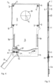
Fig. 1 zeigt eine schematische Darstellung der Funktionsweise eines Zubehörteils 1, welches in dieser beispielhaften Ausführungsform als eine Kopfplatte zur Verwendung bei einem Transferboard oder einem Operationstisch ausgestaltet ist. Insbesondere kann die Kopfplatte 1 verwendet werden, um den Kopf eines Patienten während bildgebender Verfahren, wie beispielsweise CT, Angiographie, Röntgenaufnahmen oder MRT, abzustützen. Wie weiter unten detailliert erläutert, wird durch ihre Struktur und Zusammensetzung der Kopfplatte 1 die Entstehung von Artefakten in einem Bild des darauf liegenden Patienten weitgehend minimiert. - Die Kopfplatte 1 hat einen Einschubbereich 2, mit dem sie in eine entsprechende Aufnahme des Transferboards oder des Operationstisches eingeschoben werden kann. An den Einschubbereich 2 schließt sich ein Auflagebereich 3 an, der den Kopf eines Patienten abstützt. Die Kopfplatte 1 umfasst eine erste, obere Platte 4 und eine zweite, untere Platte 5, welche übereinander angeordnet sind. Wie in
Fig. 1 schematisch dargestellt ist, können die erste Platte 4 und die zweite Platte 5 gegeneinander verdreht werden, so dass jeweils Klemmvorsprünge 6 an der ersten Platte 4 und Klemmvorsprünge 7 an der zweiten Platte 5 relativ zueinander bewegt werden. -
Fig. 2 illustriert die durch die Verdrehung der beiden Platten 4, 5 gegeneinander resultierende Klemmung: wenn der Einschubbereich 2 der Kopfplatte 1 in einer Aufnahmenut 8 eines Transferboards oder eines Operationstisches eingeschoben ist, werden bei der hier dargestellten Ausführungsform Keilprofile der jeweiligen Klemmvorsprünge 6, 7 in entsprechend geformte Abschnitte der M-förmigen Aufnahmenut 8 eingeführt. Bei einer Verdrehung der beiden Platten 4, 5 relativ zueinander wird somit auf einer Seite ein Klemmvorsprung 6 der ersten Platte 4 gegen die entsprechenden Oberflächen der Aufnahmenut 8 gepresst, und auf der gegenüberliegenden Seite der Aufnahmenut wird ein Klemmvorsprung 7 der zweiten Platte 5 gegen die entsprechenden Oberflächen der Aufnahmenut 8 gepresst. Damit wird die Kopfplatte 1 in der Aufnahmenut 8 fixiert und dabei automatisch in der Aufnahmenut 8 zentriert. - Wie aus der schematischen Darstellung von
Fig. 2 erkennbar ist, sorgt das keilförmige Profil der Klemmvorsprünge 6 und 7 und die M-Form der Aufnahmenut 8 dafür, dass jeder Klemmvorsprung an zwei seiner Oberflächen gegen die entsprechenden Innenflächen der Aufnahmenut 8 gepresst wird, um eine sichere Fixierung der Kopfplatte 1 zu erzielen. Weiterhin bewirkt die Anordnung der schrägen Flächen im Keilprofil der Klemmvorsprünge 6, 7 und die M-Form der Aufnahmenut 8, dass bei einer Klemmung die beiden Platten 4, 5 auseinander gespreizt werden. Dadurch kann sichergestellt werden, dass eine Verdrehung der beiden Platten 4, 5 relativ zueinander auch dann noch möglich ist, wenn die Kopfplatte in der Aufnahmenut 8 eingeklemmt ist. -
Fig. 3 zeigt eine schematische Draufsicht auf die Kopfplatte 1 ausFig. 1 , die in eine Aufnahmenut 8 eines Transferboards oder eines Operationstisches eingeführt ist. Dabei ist zu erkennen, dass die Verklemmung jeweils an den Ecken des Einschubbereichs 2 der Kopfplatte 1 erfolgt, während der Auflagebereich 3 der Kopfplatte 1 über das Transferboard bzw. den Operationstisch hinaussteht und somit ungehinderten Zugang zum Kopf des Patienten ermöglicht. Weiterhin ist inFig. 3 eine Drehachse 9 eingezeichnet, der in der Mitte des Einschubbereichs liegt. Dadurch sind die Hebelarme für alle Klemmpunkte jeweils gleich lang, so dass eine symmetrische Verteilung der entsprechenden Klemmkräfte erreicht wird. Wie inFig. 3 schematisch dargestellt, kann die Drehachse 9 durch eine optionale Lagerscheibe 10 definiert sein, die in entsprechenden Aufnahmen der einander zugewandten Flächen der ersten und der zweiten Platte 4, 5 angeordnet ist. - Um Artefakte in Aufnahmen eines auf der Kopfplatte 1 liegenden Patienten bei bildgebenden Verfahren möglichst zu vermeiden, können die beiden Platten 4, 5 und die optionale Lagerscheibe 10 jeweils aus Hartpapier oder aus einem anderen Material gefertigt sein, das für die verwendete Strahlung bei Röntgenaufnahmen oder bei CT- oder Angiographie-Aufnahmen durchlässig ist. Die Lagerscheibe 10 ist bei der gezeigten Ausführungsform als separates Bauteil ausgeführt, kann jedoch auch in eine der beiden Platten 4, 5 integriert sein, oder auch weggelassen werden.
-
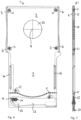
Fig. 4 zeigt eine Draufsicht auf eine Kopfplatte 1 gemäß einer Ausführungsform in einem nicht verriegelten Zustand. Dabei sind die erste Platte 4 und die zweite Platte 5 in einer Ausgangsstellung zueinander ausgerichtet, in der im Einschubbereich 2 die Kanten der beiden Platten 4, 5 im Wesentlichen parallel zueinander verlaufen, um ein Einschieben der Kopfplatte 1 in die Aufnahmenut 8 (sieheFig. 2 und 3 ) zu ermöglichen. Dabei sind die jeweiligen Klemmvorsprünge 6, 7 der beiden Platten 4, 5 im Wesentlichen bündig mit der jeweiligen Kante der angrenzenden Platte 4, 5 angeordnet. - Wie aus der dazugehörigen Seitenansicht von
Fig. 5 erkennbar, ist die Lagerscheibe 10 lediglich zwischen die beiden Platten 4, 5 eingelegt. Um ein unbeabsichtigtes Auseinanderfallen der Kopfplatte 1 zu verhindern, können daher in den Randbereichen des Einschubbereichs 2 jeweils Verliersicherungen 11 vorgesehen sein. In dem gezeigten Beispiel umfasst jede Verliersicherung 11 einen Bolzen, der an einer der beiden Platten 4, 5 befestigt ist und in eine Nut an der anderen der beiden Platten 4, 5 eingreift. Damit ermöglichen die Verliersicherungen 11 die Drehbewegung der beiden Platten 4, 5 relativ zueinander, indem der Bolzen in der entsprechend geformten Nut der Verliersicherung 11 gleitet. Weitere Verliersicherungen 11 können auch in den Randbereichen des Auflagebereichs 3 der Kopfplatte 1 vorgesehen sein. - Ein Betätigungsmechanismus 12 zum Verdrehen der beiden Platten 4, 5 gegeneinander um die Drehachse 9 ist bei der gezeigten Ausführungsform an einem Ende des Auflagebereichs 3 der Kopfplatte 1 angeordnet. Der Betätigungsmechanismus 12 umfasst einen Betätigungshebel 13, welcher über einen Exzentermechanismus 14, 15 die Verdrehung der beiden Platten 4, 5 relativ zueinander bewirkt. Dabei sind an den beiden Platten 4, 5 jeweils Stifte 14 befestigt, von denen ein Stift 14 eine Drehachse des Betätigungshebels 13 definiert, und der andere Stift 14 in einer Nut bzw. einem Schlitz 15 im Betätigungshebel 13 geführt wird. Die Formgebung der Nut bzw. des Schlitzes 15 des Betätigungshebels 13 wird weiter unten in Zusammenhang mit
Fig. 8 und 9 detailliert beschrieben. - Wie in der Seitenansicht von
Fig. 5 ersichtlich, ist der Betätigungshebel 13 bei der gezeigten Ausführungsform in der Ebene der beiden Platten 4, 5 angeordnet und ist so bemessen, dass er nicht über die jeweiligen oberen und unteren Oberflächen der beiden Platten 4, 5 hinausragt. Durch die Anordnung des Betätigungsmechanismus 12 an dem vom Einschubbereich 2 abgewandten Ende der Kopfplatte 1 wird einerseits erreicht, dass durch den großen Abstand zwischen Betätigungshebel 13 und Drehachse 9 nur geringe Betätigungskräfte aufgebracht werden müssen. Andererseits ist damit der Betätigungsmechanismus 12 auch außerhalb eines Bildbereichs angeordnet, in dem Aufnahmen eines auf der Kopfplatte 1 angeordneten Patienten aufgenommen werden. Daher können eventuell vorhandene Bolzen oder Kanten des Betätigungsmechanismus 12 keine Artefakte in einem Röntgenbild oder dergleichen erzeugen. - In dem hier gezeigten Beispiel sind Schlitze 16 im Auflagebereich 3 der ersten Platte 4 der Kopfplatte vorgesehen. Diese Schlitze können zur Befestigung weiterer Zubehörkomponenten genutzt werden.
-
Fig. 6 und Fig. 7 zeigen jeweils eine Draufsicht und eine Seitensicht der Kopfplatte 1 ausFig. 4 und 5 , wobei jedoch der Betätigungshebel 13 in seine Verriegelungsstellung verdreht wurde, so dass die beiden Platten 4, 5 gegeneinander verdreht sind und die Klemmvorsprünge 6, 7 jeweils über die Kanten der angrenzenden Platte hinausragen. Damit kann die Kopfplatte 1, wie inFig. 2 gezeigt, in einer Aufnahmenut 8 fixiert werden. - Wie aus
Fig. 6 und 7 ersichtlich, steht der Betätigungshebel 13 in seiner Verriegelungsstellung nicht über die äußeren Abmessungen der oberen Platte 4 hervor, weder seitlich noch nach oben oder unten. Der Betätigungshebel 13 ist daher in seiner Verriegelungsstellung von oben nicht sichtbar. InFig. 7 ist erkennbar, dass die beiden Platten 4, 5 im Bereich des Betätigungshebels 13 von ihrer Trennebene her ausgedünnt sind, so dass der Betätigungshebel 13 zwischen den beiden Platten aufgenommen werden kann. Ein Vorsprung 17 an einem Ende des Betätigungshebels 13 ermöglicht es dem Benutzer, den Betätigungshebel 13 in seiner Verriegelungsstellung zu greifen und zum Lösen der Klemmung wieder in die inFig. 4 gezeigte offene Stellung zu bewegen. -
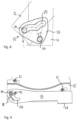
Fig. 8 und 9 zeigen Detailansichten des Betätigungsmechanismus 12. In der schematischen Darstellung vonFig. 8 ist ein erster Stift 14, welcher die Drehachse des Betätigungshebels 13 definiert, an der oberen Platte 4 befestigt und ein zweiter Stift 14, der an der unteren Platte 5 befestigt ist, wird in der Nut 15 des Betätigungshebels 13 geführt. Durch die Formgebung der Nut 15 kann der Kraft- bzw. Momentverlauf beim Bewegen des Betätigungshebels 13 von seiner offenen Stellung (sieheFig. 4 ) in seine Verriegelungsstellung (sieheFig. 6 ) beeinflusst werden. - Ein einfaches Beispiel für eine derartige Formgebung wäre eine kreisabschnittsförmige Nut, welche eine gleichmäßige Betätigungskraft über den gesamten Verstellweg des Betätigungshebels 13 erzielen würde. Bei einem gleichförmigen Kraftverlauf wäre es jedoch für den Benutzer schwierig, abzuschätzen, wann eine sichere Fixierung der Kopfplatte 1 in der Aufnahmenut erreicht ist. Außerdem müsste der Betätigungshebel 13 dann in seiner Verriegelungsstellung gesichert werden, um ein unbeabsichtigtes Lösen der Verklemmung zu verhindern.
- Daher wird gemäß einiger Ausführungsformen eine Formgebung der Nut 15 gewählt, bei welcher eine Betätigungskraft beim Bewegen des Betätigungshebels 13 von seiner offenen Stellung in seine Verriegelungsstellung zunächst ansteigt, um dann vor Erreichen der Verriegelungsstellung wieder abzufallen. Dadurch ergibt sich für den Benutzer ein fühlbares Einrasten des Betätigungshebels in einer Stellung, in der bereits eine Verklemmung der Kopfplatte 1 in der Aufnahmenut 8 erreicht ist. Weiterhin kann vorgesehen sein, dass die Betätigungskraft nach Überschreiten des Maximalwerts bei einem relativ niedrigen Wert bleibt, so dass der Benutzer den Betätigungshebel mit wenig Kraftaufwand nach dem "Einrasten" der Verklemmung auf dem letzten Stück des Verstellweges bis in die Verriegelungsstellung (siehe
Fig. 6 ) bewegen kann. - Dadurch kann sich der Benutzer sowohl taktil als auch visuell vergewissern, dass die Kopfplatte 1 sicher in der Aufnahmenut 8 fixiert ist, indem er beim Bewegen des Betätigungshebels 13 einmal das Überwinden des Punktes maximaler Betätigungskraft spürt, und anschließend mit wenig Kraftaufwand den Betätigungshebel 13 in seine Endposition in der Verriegelungsstellung bewegen kann. Durch diesen Kraftverlauf wird außerdem ein unbeabsichtigtes Lösen der Verklemmung vermieden, da beim Zurückführen des Betätigungshebels 13 von der Verriegelungsstellung in die geöffnete Stellung wieder ein Punkt maximaler Betätigungskraft überwunden werden muss.
-
Fig. 9 illustriert einen weiteren Aspekt des Betätigungsmechanismus 12 gemäß einiger Ausführungsformen. Hierbei ist eine schlitzförmige Aussparung 18 im Betätigungshebel 13 vorgesehen, welche im Wesentlichen parallel zu einer Kante der Nut 15 verläuft. Dadurch kann diese Kante der Nut 15 elastisch verformt werden, so dass Fertigungstoleranzen der Kopfplatte 1 oder der Aufnahmenut 8 durch eine elastische Verformung der Nut 15 beim Verstellen des Betätigungshebels 13 ausgeglichen werden können. - Wie in
Fig. 10 und11 gezeigt, können an den beiden Platten 4, 5 jeweils Anschlagsvorsprünge 19 vorgesehen sein, welche eine Einschubtiefe der Kopfplatte 1 in die Aufnahmenut 8 begrenzen.Fig. 11 zeigt weiterhin, dass die Verliersicherungen 11 nur in Randbereichen der Kopfplatte 1 vorgesehen sind, so dass ein Bereich der Kopfplatte 1, in dem der Kopf eines Patienten liegt, frei von Komponenten ist, welche Artefakte in einer Bildaufnahme erzeugen könnten. -
Fig. 12 verdeutlicht die Position und Funktion der optionalen Lagerscheibe 10. Aus der Explosionsdarstellung vonFig. 12 ist ersichtlich, dass die Lagerscheibe 10 in runden Ausnehmungen 20 an den jeweiligen Innenseiten der Platten 4 und 5 aufgenommen wird. Die Oberflächen der Lagerscheibe 10 und die Flächen der Ausnehmungen 20 bilden dabei jeweils Lagerflächen für die Drehbewegung der beiden Platten 4,5 relativ zueinander. AusFig. 12 ist weiterhin ersichtlich, dass im Bereich der Lagerscheibe 10 keinerlei Befestigungselemente an den Platten 4, 5 vorgesehen sind. Dadurch können Artefakte in Bildaufnahmen des Kopfes eines Patienten vermieden werden. Gleichzeitig wird durch die Lagerscheibe 10 und die runden Ausnehmungen 20 in der jeweiligen Innenseite der Platten 4, 5 die Drehachse 9 definiert. Durch Weglassen der Lagerscheibe 10 können Artefakte weiter reduziert werden. Die Platten 4, 5 bilden ohne die Lagerscheibe 10 nämlich ein noch homogeneres Material im durchleuchtbaren Bereich. -
Fig. 13 bis 15 verdeutlichen die Anordnung und die Funktion des Betätigungsmechanismus 12 mit dem Betätigungshebel 13. AusFig. 13 ist ersichtlich, dass je nach Ausgestaltung des Betätigungshebels der Nocken, der in der Nut bzw. in dem Schlitz 15 im Betätigungshebel geführt wird, an der ersten oder der zweiten Platte 4, 5 angebracht wird, wobei der Betätigungshebel 13 dann drehbar an der jeweils anderen Platte befestigt werden kann. InFig. 14 ist die Form der Nut bzw. des Schlitzes 15, mittels deren der Kraft- bzw-Momentenverlauf eingestellt werden kann, vergrößert gezeigt. Hierbei ist ersichtlich, dass der Rastpunkt des Betätigungshebels durch einen entsprechend geformten Abschnitt 21 in der Nut bzw. dem Schlitz 15 erzielt werden kann.Fig. 15 zeigt den Betätigungshebel in einer Position, in der er ohne großen Kraftaufwand, nach dem Passieren des Rastpunktes, in seine Endposition, die beispielsweise inFig. 13 gezeigt ist, bewegt werden kann. - Zusammenfassend ermöglicht die Kopfplatte 1 der voranstehend beschriebenen Ausführungsformen somit eine einfache Montage und Demontage in einer Aufnahmenut 8 durch Einschieben und Verklemmen mittels des Betätigungsmechanismus 12, ohne dass dafür der Patient angehoben werden müsste. Die scherenartige Verklemmung der Kopfplatte 1 in der Aufnahmenut 8 ermöglicht eine stufenlose Positionierung eines Auflagebereichs 3 der Kopfplatte 1 in Längsrichtung der Aufnahmenut 8 für unterschiedliche große Patienten oder unterschiedliche Liegepositionen eines Patienten.
- Die Kopfplatte 1 kann dabei fast vollständig aus einem röntgendurchlässigen Material, wie beispielsweise aus Hartpapier, Kunststoff oder Kohlefaser, hergestellt werden, um Artefakte in einem Röntgenbild, einer CT-Aufnahme oder einer Angiographie-Aufnahme eines Patienten, dessen Kopf auf der Kopfplatte 1 liegt, weitgehend zu vermeiden. Die Kopfplatte 1 umfasst dabei nur wenige Stifte oder Bolzen, und diese sind alle in Randbereichen der Kopfplatte 1 angeordnet, so dass sie bei bildgebenden Verfahren nicht stören.
- Durch die Keilform der jeweiligen Klemmvorsprünge 6, 7 an den beiden Platten wird jede Klemmvorsprung über eine Zwei-Flächen-Verklemmung in der entsprechend M-förmig ausgebildeten Aufnahmenut 8 eingeklemmt. Dadurch kann eine besonders sichere Fixierung der Kopfplatte 1 erreicht werden, da jeder Klemmvorsprung 6, 7 mit zwei Reibflächen gegen entsprechende Oberflächen der Aufnahmenut 8 gedrückt wird.
- Bei den voranstehend beschriebenen Ausführungsformen sind zwei Platten 4, 5 vorgesehen. Alternativ und nicht zum Geltungsbereich der Ansprüche gehörend wäre auch denkbar, dass die Kopfplatte nur eine einzige Platte umfasst, an der eine nicht zwingend plattenförmige Klemmvorrichtung, wie beispielsweise ein diagonal verlaufender Balken mit Klemmvorsprüngen oder Klemmelementen, drehbar befestigt ist. Auch mit einem nicht plattenförmigen weiteren Element könnte eine scherenartige Klemmung an den Ecken eines Einschubbereichs einer Kopfplatte, wie voranstehend beschrieben, erreicht werden. Die hier gezeigte Ausführung mit zwei Platten 4, 5 hat jedoch den Vorteil, dass die Struktur insgesamt in einem Bereich, in dem der Patient aufliegt, relativ homogen ist und somit in einem Röntgenbild oder dergleichen weniger Artefakte erzeugt.
- Bei den voranstehend beschriebenen Ausführungsformen wird ein Exzentermechanismus verwendet, um die beiden Platten 4, 5 gegeneinander zu verdrehen. Alternativ kann auch ein Spindelmechanismus oder dergleichen verwendet werden.
Claims (12)
- Zubehörteil (1) für ein medizinisches Gerät, insbesondere für einen Operationstisch oder ein Transferboard, umfassend:eine erste Platte (4) zum Abstützen eines Körperteils eines Patienten, und eine zweite Platte (5), welche relativ zur ersten Platte (4) in einem vorbestimmten Verstellbereich bewegbar ist, wobei die erste Platte (4) und die zweite Platte (5) in eine Halterung (8) an dem medizinischen Gerät einführbar sind, undeine erste Klemmfläche, und eine von der ersten Klemmfläche beabstandete zweite Klemmfläche, wobei die erste Klemmfläche an der ersten Platte (4) angeordnet ist und die zweite Klemmfläche an der zweiten Platte (5) angeordnet ist,wobei eine Bewegung der zweiten Platte (5) relativ zur ersten Platte (4) eine Bewegung der zweiten Klemmfläche relativ zur ersten Klemmfläche in einer Richtung im Wesentlichen parallel zu einer Oberfläche der ersten oder zweiten Platte (4, 5) bewirkt, um eine Klemmkraft zwischen dem Zubehörteil und der geeigneten Halterung (8) an dem medizinischen Gerät zu erhöhen oder zu verringern,wobei die erste Platte (4) und die zweite Platte (5) übereinander angeordnet sind.
- Zubehörteil (1) nach Anspruch 1, wobei die Bewegung der zweiten Platte (5) relativ zur ersten Platte (4) eine Drehbewegung ist.
- Zubehörteil (1) nach Anspruch 2, ferner umfassend eine Lagerfläche zwischen der ersten und der zweiten Platte (4, 5), wobei die Lagerfläche einen Durchmesser aufweist, der kleiner als eine Breitenabmessung der ersten oder der zweiten Platte (4, 5) ist, wobei eine Lagerscheibe (10) zwischen der ersten und der zweiten Platte (4, 5) angeordnet ist, wobei die Lagerscheibe (10) wenigstens einen Teil der Lagerfläche bildet, wobei vorzugsweise die Drehung der zweiten Platte (5) relativ zur ersten Platte (4) um eine durch die Lagerfläche verlaufende Drehachse (9) stattfindet.
- Zubehörteil (1) nach einem der vorangehenden Ansprüche, ferner umfassend eine dritte Klemmfläche an der ersten Platte (4) und eine vierte Klemmfläche an der zweiten Platte (5), wobei sich bei einer Bewegung der zweiten Platte (5) relativ zur ersten Platte (4) die dritte Klemmfläche relativ zur vierten Klemmfläche bewegt, wobei vorzugsweise eine Bewegung der zweiten Platte (5) relativ zur ersten Platte (4) bewirkt, dass die erste und die vierte Klemmfläche eine erste Seite der Halterung (8) an dem medizinischen Gerät kontaktieren, und dass die zweite und/oder die dritte Klemmfläche eine zweite Seite der Halterung (8) kontaktieren.
- Zubehörteil (1) nach einem der vorangehenden Ansprüche, wobei die erste und die zweite Platte (4, 5) derart ausgelegt sind, dass sie mit einem Einschubbereich (2) in eine Aufnahmenut (8) an dem medizinischen Gerät einschiebbar sind, und wobei die Verdrehung der zweiten Platte (5) relativ zur ersten Platte (4) eine Verklemmung des Zubehörteils (1) in der Aufnahmenut (8) bewirkt, und wobei vorzugsweise die erste und/oder die zweite Klemmfläche an einem jeweiligen Klemmvorsprung (6) vorgesehen ist, welcher an wenigstens einer Ecke des Einschubbereichs (2) angeordnet ist.
- Zubehörteil (1) nach Anspruch 5, wobei die erste und die zweite Platte (4) im Bereich der jeweiligen Klemmflächen einen im Wesentlichen keilförmigen Querschnitt aufweisen, wobei ein Keil jeweils zwei Reibflächen zum Kontaktieren des medizinischen Geräts aufweist.
- Zubehörteil (1) nach einem der vorangehenden Ansprüche, wobei die Klemmvorrichtung einen Betätigungshebel (13) umfasst, der über einen Betätigungsmechanismus (12) eine Verdrehung der zweiten Platte (5) relativ zur ersten Platte (4) bewirkt, wobei vorzugsweise der Betätigungshebel (13) drehbar an der ersten oder der zweiten Platte (4, 5) befestigt ist, und eine Nut (15) aufweist, in die ein Stift (14), der an der zweiten oder der ersten Platte (5, 4) befestigt ist, eingreift.
- Zubehörteil (1) nach Anspruch 7, wobei die Nut (15) im Betätigungshebel (13) derart geformt ist, dass eine Betätigungskraft bei Betätigen des Betätigungshebels (13) zum Verdrehen des Klemmelements (5, 7) relativ zur ersten Platte (4) zunächst ansteigt, dann einen Maximalwert erreicht und vor Erreichen der Klemmposition des Zubehörteils (1) wieder auf einen Wert abfällt, der unter dem Maximalwert liegt.
- Zubehörteil (1) nach einem der Ansprüche 7 oder 8, wobei eine Kante der Nut (15) elastisch verformbar ist, so dass die Nut (15) während der Betätigung des Betätigungshebels (13) durch den Stift (14) elastisch verformt werden kann, wobei vorzugsweise eine schlitzförmige Aussparung (18) im Betätigungshebel (13) vorgesehen ist, welche im Wesentlichen parallel zu einer Kante der Nut (15) verläuft.
- Zubehörteil (1) nach einem der Ansprüche 7 bis 9, wobei der Betätigungshebel (13) und der Betätigungsmechanismus (12) in einem Randbereich der ersten Platte (4) angeordnet sind.
- Zubehörteil (1) nach einem der vorangehenden Ansprüche, wobei die erste und die zweite Platte (4, 5) aus einem Material, wie beispielsweise Kunststoff, Hartpapier oder einem Kohlefaserwerkstoff, hergestellt sind, das durchlässig für Röntgenstrahlung ist, und wobei in einem zentralen Bereich der ersten Platte (4) keine Komponenten vorgesehen sind, die undurchlässig für Röntgenstrahlung sind.
- Zubehörteil (1) nach einem der vorangehenden Ansprüche, wobei eine Verliersicherung (11) vorgesehen ist, die in wenigstens einem Randbereich des Einschubbereichs (2) der ersten Platte (4) angeordnet ist, und wobei die beiden Platten (4, 5) mittels der Verliersicherung (11) aneinander befestigt sind.
Applications Claiming Priority (2)
| Application Number | Priority Date | Filing Date | Title |
|---|---|---|---|
| DE102016113050.8A DE102016113050B4 (de) | 2016-07-15 | 2016-07-15 | Zubehörteil mit Klemmbefestigung und Schnittstelle |
| PCT/EP2017/066485 WO2018010993A1 (de) | 2016-07-15 | 2017-07-03 | Zubehörteil mit klemmbefestigung |
Publications (2)
| Publication Number | Publication Date |
|---|---|
| EP3484431A1 EP3484431A1 (de) | 2019-05-22 |
| EP3484431B1 true EP3484431B1 (de) | 2023-08-30 |
Family
ID=59315601
Family Applications (1)
| Application Number | Title | Priority Date | Filing Date |
|---|---|---|---|
| EP17737760.3A Active EP3484431B1 (de) | 2016-07-15 | 2017-07-03 | Zubehörteil mit klemmbefestigung |
Country Status (9)
| Country | Link |
|---|---|
| US (1) | US11039970B2 (de) |
| EP (1) | EP3484431B1 (de) |
| JP (1) | JP7021181B2 (de) |
| KR (1) | KR20190029586A (de) |
| CN (1) | CN109475457B (de) |
| BR (1) | BR112019000393A2 (de) |
| DE (1) | DE102016113050B4 (de) |
| RU (1) | RU2019100523A (de) |
| WO (1) | WO2018010993A1 (de) |
Family Cites Families (24)
| Publication number | Priority date | Publication date | Assignee | Title |
|---|---|---|---|---|
| US4526355A (en) * | 1982-09-29 | 1985-07-02 | Moore Robert R | Arthroscopic leg holder |
| US4576351A (en) * | 1984-06-15 | 1986-03-18 | Brink T A | Portable stroke victims arm rest |
| US4964400A (en) * | 1988-04-19 | 1990-10-23 | Lincoln Mills, Inc. | Surgical limb supporting apparatus with tension measuring device |
| DE4441046C2 (de) * | 1994-11-18 | 2000-05-18 | Siemens Ag | Bewegliche Positionierhilfe für die kinematische Untersuchung der Abduktion und Rotation des Schultergelenks |
| US5940912A (en) * | 1996-11-21 | 1999-08-24 | Amatech Corporation | Surgical armboard |
| JP2003135446A (ja) | 2001-10-30 | 2003-05-13 | Toshiba Corp | 画像診断用寝台装置の付属品 |
| US7222826B1 (en) * | 2002-11-23 | 2007-05-29 | Andrew Berglund | Adaptive arm support |
| JP2005168881A (ja) | 2003-12-12 | 2005-06-30 | Mizuho Co Ltd | 被検者支持装置 |
| EP1957024A4 (de) | 2005-12-05 | 2009-05-13 | Scott M Ahlman | Patienten-einzelflächensystem |
| DE202007006965U1 (de) * | 2007-05-11 | 2008-09-18 | Rüthlein, Christian | Halte- oder Entspannungsbügel für Liegen und Entbindungsbetten |
| US8302228B2 (en) * | 2009-02-24 | 2012-11-06 | Emad Aboujaoude | Lower extremity surgical positioning device |
| US8700131B2 (en) * | 2009-05-13 | 2014-04-15 | Merit Medical Systems, Inc. | Radial cardiac catheterization board |
| US8756733B2 (en) * | 2009-11-26 | 2014-06-24 | Noel Robert Hughes | Patient pad for operating theatre |
| US20130193280A1 (en) * | 2012-02-01 | 2013-08-01 | Rodello A. Diamante | Medical Arm Support |
| US9125784B2 (en) * | 2012-08-28 | 2015-09-08 | Merit Medical Systems, Inc. | Arm positioning cushion |
| WO2013154509A1 (en) * | 2012-09-20 | 2013-10-17 | Ercan Ertugrul | Upper extremity support device for vascular imaging |
| US9636268B1 (en) * | 2013-06-18 | 2017-05-02 | Darlene Bedillion | Articulating surgical armrest |
| US20150101619A1 (en) * | 2013-10-10 | 2015-04-16 | Semler Technologies, Inc. | Integrated Armboard and Wrist Support Apparatuses and Methods of Use |
| CH708922A1 (de) | 2013-12-04 | 2015-06-15 | Schär Engineering Ag | Transfereinrichtung für eine Therapieliege. |
| DE202014102410U1 (de) * | 2014-05-22 | 2014-07-17 | Gaugler & Lutz Ohg | Lagerungselement |
| US20160317371A1 (en) * | 2015-05-02 | 2016-11-03 | The Board Of Regents, The University Of Texas System | Apparatus and Method for Supporting a Patient's Arm During a Medical Procedure |
| US10267350B2 (en) * | 2015-08-12 | 2019-04-23 | Semler Technologies, Inc. | Integrated armboard and wrist support apparatuses and methods of use |
| US9414983B1 (en) * | 2015-09-24 | 2016-08-16 | AG Technical Solutions, LLC | Adjustable patient arm support system |
| CN105411762B (zh) * | 2016-01-14 | 2017-04-05 | 中国人民解放军第三军医大学第二附属医院 | 移动病床 |
-
2016
- 2016-07-15 DE DE102016113050.8A patent/DE102016113050B4/de active Active
-
2017
- 2017-07-03 JP JP2019501615A patent/JP7021181B2/ja active Active
- 2017-07-03 CN CN201780043807.5A patent/CN109475457B/zh active Active
- 2017-07-03 EP EP17737760.3A patent/EP3484431B1/de active Active
- 2017-07-03 RU RU2019100523A patent/RU2019100523A/ru not_active Application Discontinuation
- 2017-07-03 WO PCT/EP2017/066485 patent/WO2018010993A1/de not_active Ceased
- 2017-07-03 KR KR1020197001113A patent/KR20190029586A/ko not_active Ceased
- 2017-07-03 BR BR112019000393A patent/BR112019000393A2/pt not_active Application Discontinuation
-
2019
- 2019-01-08 US US16/242,462 patent/US11039970B2/en active Active
Also Published As
| Publication number | Publication date |
|---|---|
| US20190142676A1 (en) | 2019-05-16 |
| WO2018010993A1 (de) | 2018-01-18 |
| RU2019100523A (ru) | 2020-08-18 |
| KR20190029586A (ko) | 2019-03-20 |
| EP3484431A1 (de) | 2019-05-22 |
| CN109475457A (zh) | 2019-03-15 |
| JP2019524238A (ja) | 2019-09-05 |
| BR112019000393A2 (pt) | 2019-04-24 |
| DE102016113050B4 (de) | 2019-07-04 |
| US11039970B2 (en) | 2021-06-22 |
| CN109475457B (zh) | 2021-06-11 |
| JP7021181B2 (ja) | 2022-02-16 |
| DE102016113050A1 (de) | 2018-01-18 |
Similar Documents
| Publication | Publication Date | Title |
|---|---|---|
| EP3057557B1 (de) | Röntgenoptimierte vorrichtung zum lagern eines patienten | |
| EP3057556B1 (de) | Befestigungseinheit zur befestigung einer vorrichtung zum lagern eines zu röntgenden patienten an einem operationstisch | |
| DE69021428T2 (de) | Wirbelsäulenimplantat für Osteosesyntheseeinrichtung. | |
| EP1900566A2 (de) | Drehbarer Fahrzeugsitz | |
| EP2365783A2 (de) | Klemmhalterung | |
| DE202014011303U1 (de) | Ein- und Ausklappvorrichtung für eine Fuß- und/oder Beinstütze eines Sitz- und/oder Liegemöbels | |
| EP3057558B1 (de) | Patientenlagereinheit für eine vorrichtung zum lagern eines zu röntgenden patienten während einer operation | |
| DE102009020874B4 (de) | Vorrichtung zum temporären Verbinden eines bewegbaren Gegenstandes mit einer Halteschiene | |
| DE102012012134B4 (de) | Als Kindersitz ausgebildete Sicherheitssitzvorrichtung | |
| EP2848159A1 (de) | Griff | |
| DE102021214820B4 (de) | Verbindungsanordnung und Bürostuhl | |
| DE102019135621A1 (de) | Chirurgische Schädelklemme mit Feststellstellmechanismus | |
| DE102016113050B4 (de) | Zubehörteil mit Klemmbefestigung und Schnittstelle | |
| DE102012220550A1 (de) | Verstellanordnung mit linearem verlagerungsweg | |
| EP3498531B1 (de) | Vorrichtung, insbesondere sitzschale, mit mehreren beweglichen verstellelementen | |
| DE102020109855A1 (de) | Chirurgischer Retraktor | |
| DE102013009090B4 (de) | Mechanisches Befestigungssystem | |
| WO2015104109A1 (de) | Gehäuseanordnung | |
| DE102024204264B3 (de) | Rastfreie Arretierung eines Zusatzkörpers relativ zu einem Basiskörper | |
| AT525871B1 (de) | Tisch mit beweglichem Führungselement | |
| WO2010108742A1 (de) | Verstellvorrichtung | |
| WO2025021508A1 (de) | Operationstisch mit vorrichtung zur einstellung der position eines beweglichen operationstischteils | |
| EP0690940A1 (de) | Schienenanordnung | |
| DE202020101356U1 (de) | Patientenlagerungsvorrichtung und Patientenlagerungseinrichtung | |
| AT11949U1 (de) | Werkzeuglos zerleg- und zusammensetzbares möbel |
Legal Events
| Date | Code | Title | Description |
|---|---|---|---|
| STAA | Information on the status of an ep patent application or granted ep patent |
Free format text: STATUS: UNKNOWN |
|
| STAA | Information on the status of an ep patent application or granted ep patent |
Free format text: STATUS: THE INTERNATIONAL PUBLICATION HAS BEEN MADE |
|
| PUAI | Public reference made under article 153(3) epc to a published international application that has entered the european phase |
Free format text: ORIGINAL CODE: 0009012 |
|
| STAA | Information on the status of an ep patent application or granted ep patent |
Free format text: STATUS: REQUEST FOR EXAMINATION WAS MADE |
|
| 17P | Request for examination filed |
Effective date: 20190111 |
|
| AK | Designated contracting states |
Kind code of ref document: A1 Designated state(s): AL AT BE BG CH CY CZ DE DK EE ES FI FR GB GR HR HU IE IS IT LI LT LU LV MC MK MT NL NO PL PT RO RS SE SI SK SM TR |
|
| AX | Request for extension of the european patent |
Extension state: BA ME |
|
| DAV | Request for validation of the european patent (deleted) | ||
| DAX | Request for extension of the european patent (deleted) | ||
| STAA | Information on the status of an ep patent application or granted ep patent |
Free format text: STATUS: EXAMINATION IS IN PROGRESS |
|
| 17Q | First examination report despatched |
Effective date: 20210312 |
|
| GRAP | Despatch of communication of intention to grant a patent |
Free format text: ORIGINAL CODE: EPIDOSNIGR1 |
|
| STAA | Information on the status of an ep patent application or granted ep patent |
Free format text: STATUS: GRANT OF PATENT IS INTENDED |
|
| INTG | Intention to grant announced |
Effective date: 20230327 |
|
| GRAS | Grant fee paid |
Free format text: ORIGINAL CODE: EPIDOSNIGR3 |
|
| GRAA | (expected) grant |
Free format text: ORIGINAL CODE: 0009210 |
|
| STAA | Information on the status of an ep patent application or granted ep patent |
Free format text: STATUS: THE PATENT HAS BEEN GRANTED |
|
| P01 | Opt-out of the competence of the unified patent court (upc) registered |
Effective date: 20230629 |
|
| AK | Designated contracting states |
Kind code of ref document: B1 Designated state(s): AL AT BE BG CH CY CZ DE DK EE ES FI FR GB GR HR HU IE IS IT LI LT LU LV MC MK MT NL NO PL PT RO RS SE SI SK SM TR |
|
| REG | Reference to a national code |
Ref country code: GB Ref legal event code: FG4D Free format text: NOT ENGLISH |
|
| REG | Reference to a national code |
Ref country code: CH Ref legal event code: EP |
|
| REG | Reference to a national code |
Ref country code: DE Ref legal event code: R096 Ref document number: 502017015309 Country of ref document: DE |
|
| REG | Reference to a national code |
Ref country code: IE Ref legal event code: FG4D Free format text: LANGUAGE OF EP DOCUMENT: GERMAN |
|
| REG | Reference to a national code |
Ref country code: LT Ref legal event code: MG9D |
|
| REG | Reference to a national code |
Ref country code: NL Ref legal event code: MP Effective date: 20230830 |
|
| PG25 | Lapsed in a contracting state [announced via postgrant information from national office to epo] |
Ref country code: GR Free format text: LAPSE BECAUSE OF FAILURE TO SUBMIT A TRANSLATION OF THE DESCRIPTION OR TO PAY THE FEE WITHIN THE PRESCRIBED TIME-LIMIT Effective date: 20231201 |
|
| PG25 | Lapsed in a contracting state [announced via postgrant information from national office to epo] |
Ref country code: IS Free format text: LAPSE BECAUSE OF FAILURE TO SUBMIT A TRANSLATION OF THE DESCRIPTION OR TO PAY THE FEE WITHIN THE PRESCRIBED TIME-LIMIT Effective date: 20231230 |
|
| PG25 | Lapsed in a contracting state [announced via postgrant information from national office to epo] |
Ref country code: SE Free format text: LAPSE BECAUSE OF FAILURE TO SUBMIT A TRANSLATION OF THE DESCRIPTION OR TO PAY THE FEE WITHIN THE PRESCRIBED TIME-LIMIT Effective date: 20230830 Ref country code: RS Free format text: LAPSE BECAUSE OF FAILURE TO SUBMIT A TRANSLATION OF THE DESCRIPTION OR TO PAY THE FEE WITHIN THE PRESCRIBED TIME-LIMIT Effective date: 20230830 Ref country code: NO Free format text: LAPSE BECAUSE OF FAILURE TO SUBMIT A TRANSLATION OF THE DESCRIPTION OR TO PAY THE FEE WITHIN THE PRESCRIBED TIME-LIMIT Effective date: 20231130 Ref country code: LV Free format text: LAPSE BECAUSE OF FAILURE TO SUBMIT A TRANSLATION OF THE DESCRIPTION OR TO PAY THE FEE WITHIN THE PRESCRIBED TIME-LIMIT Effective date: 20230830 Ref country code: LT Free format text: LAPSE BECAUSE OF FAILURE TO SUBMIT A TRANSLATION OF THE DESCRIPTION OR TO PAY THE FEE WITHIN THE PRESCRIBED TIME-LIMIT Effective date: 20230830 Ref country code: IS Free format text: LAPSE BECAUSE OF FAILURE TO SUBMIT A TRANSLATION OF THE DESCRIPTION OR TO PAY THE FEE WITHIN THE PRESCRIBED TIME-LIMIT Effective date: 20231230 Ref country code: HR Free format text: LAPSE BECAUSE OF FAILURE TO SUBMIT A TRANSLATION OF THE DESCRIPTION OR TO PAY THE FEE WITHIN THE PRESCRIBED TIME-LIMIT Effective date: 20230830 Ref country code: GR Free format text: LAPSE BECAUSE OF FAILURE TO SUBMIT A TRANSLATION OF THE DESCRIPTION OR TO PAY THE FEE WITHIN THE PRESCRIBED TIME-LIMIT Effective date: 20231201 Ref country code: FI Free format text: LAPSE BECAUSE OF FAILURE TO SUBMIT A TRANSLATION OF THE DESCRIPTION OR TO PAY THE FEE WITHIN THE PRESCRIBED TIME-LIMIT Effective date: 20230830 |
|
| PG25 | Lapsed in a contracting state [announced via postgrant information from national office to epo] |
Ref country code: PL Free format text: LAPSE BECAUSE OF FAILURE TO SUBMIT A TRANSLATION OF THE DESCRIPTION OR TO PAY THE FEE WITHIN THE PRESCRIBED TIME-LIMIT Effective date: 20230830 Ref country code: NL Free format text: LAPSE BECAUSE OF FAILURE TO SUBMIT A TRANSLATION OF THE DESCRIPTION OR TO PAY THE FEE WITHIN THE PRESCRIBED TIME-LIMIT Effective date: 20230830 |
|
| PG25 | Lapsed in a contracting state [announced via postgrant information from national office to epo] |
Ref country code: ES Free format text: LAPSE BECAUSE OF FAILURE TO SUBMIT A TRANSLATION OF THE DESCRIPTION OR TO PAY THE FEE WITHIN THE PRESCRIBED TIME-LIMIT Effective date: 20230830 |
|
| PG25 | Lapsed in a contracting state [announced via postgrant information from national office to epo] |
Ref country code: SM Free format text: LAPSE BECAUSE OF FAILURE TO SUBMIT A TRANSLATION OF THE DESCRIPTION OR TO PAY THE FEE WITHIN THE PRESCRIBED TIME-LIMIT Effective date: 20230830 Ref country code: RO Free format text: LAPSE BECAUSE OF FAILURE TO SUBMIT A TRANSLATION OF THE DESCRIPTION OR TO PAY THE FEE WITHIN THE PRESCRIBED TIME-LIMIT Effective date: 20230830 Ref country code: ES Free format text: LAPSE BECAUSE OF FAILURE TO SUBMIT A TRANSLATION OF THE DESCRIPTION OR TO PAY THE FEE WITHIN THE PRESCRIBED TIME-LIMIT Effective date: 20230830 Ref country code: EE Free format text: LAPSE BECAUSE OF FAILURE TO SUBMIT A TRANSLATION OF THE DESCRIPTION OR TO PAY THE FEE WITHIN THE PRESCRIBED TIME-LIMIT Effective date: 20230830 Ref country code: DK Free format text: LAPSE BECAUSE OF FAILURE TO SUBMIT A TRANSLATION OF THE DESCRIPTION OR TO PAY THE FEE WITHIN THE PRESCRIBED TIME-LIMIT Effective date: 20230830 Ref country code: CZ Free format text: LAPSE BECAUSE OF FAILURE TO SUBMIT A TRANSLATION OF THE DESCRIPTION OR TO PAY THE FEE WITHIN THE PRESCRIBED TIME-LIMIT Effective date: 20230830 Ref country code: SK Free format text: LAPSE BECAUSE OF FAILURE TO SUBMIT A TRANSLATION OF THE DESCRIPTION OR TO PAY THE FEE WITHIN THE PRESCRIBED TIME-LIMIT Effective date: 20230830 Ref country code: PT Free format text: LAPSE BECAUSE OF FAILURE TO SUBMIT A TRANSLATION OF THE DESCRIPTION OR TO PAY THE FEE WITHIN THE PRESCRIBED TIME-LIMIT Effective date: 20240102 |
|
| PG25 | Lapsed in a contracting state [announced via postgrant information from national office to epo] |
Ref country code: IT Free format text: LAPSE BECAUSE OF FAILURE TO SUBMIT A TRANSLATION OF THE DESCRIPTION OR TO PAY THE FEE WITHIN THE PRESCRIBED TIME-LIMIT Effective date: 20230830 |
|
| REG | Reference to a national code |
Ref country code: DE Ref legal event code: R097 Ref document number: 502017015309 Country of ref document: DE |
|
| PLBE | No opposition filed within time limit |
Free format text: ORIGINAL CODE: 0009261 |
|
| STAA | Information on the status of an ep patent application or granted ep patent |
Free format text: STATUS: NO OPPOSITION FILED WITHIN TIME LIMIT |
|
| PG25 | Lapsed in a contracting state [announced via postgrant information from national office to epo] |
Ref country code: SI Free format text: LAPSE BECAUSE OF FAILURE TO SUBMIT A TRANSLATION OF THE DESCRIPTION OR TO PAY THE FEE WITHIN THE PRESCRIBED TIME-LIMIT Effective date: 20230830 |
|
| 26N | No opposition filed |
Effective date: 20240603 |
|
| PG25 | Lapsed in a contracting state [announced via postgrant information from national office to epo] |
Ref country code: BG Free format text: LAPSE BECAUSE OF FAILURE TO SUBMIT A TRANSLATION OF THE DESCRIPTION OR TO PAY THE FEE WITHIN THE PRESCRIBED TIME-LIMIT Effective date: 20230830 |
|
| PG25 | Lapsed in a contracting state [announced via postgrant information from national office to epo] |
Ref country code: BG Free format text: LAPSE BECAUSE OF FAILURE TO SUBMIT A TRANSLATION OF THE DESCRIPTION OR TO PAY THE FEE WITHIN THE PRESCRIBED TIME-LIMIT Effective date: 20230830 |
|
| PG25 | Lapsed in a contracting state [announced via postgrant information from national office to epo] |
Ref country code: MC Free format text: LAPSE BECAUSE OF FAILURE TO SUBMIT A TRANSLATION OF THE DESCRIPTION OR TO PAY THE FEE WITHIN THE PRESCRIBED TIME-LIMIT Effective date: 20230830 |
|
| REG | Reference to a national code |
Ref country code: CH Ref legal event code: PL |
|
| PG25 | Lapsed in a contracting state [announced via postgrant information from national office to epo] |
Ref country code: LU Free format text: LAPSE BECAUSE OF NON-PAYMENT OF DUE FEES Effective date: 20240703 |
|
| PG25 | Lapsed in a contracting state [announced via postgrant information from national office to epo] |
Ref country code: LU Free format text: LAPSE BECAUSE OF NON-PAYMENT OF DUE FEES Effective date: 20240703 |
|
| PG25 | Lapsed in a contracting state [announced via postgrant information from national office to epo] |
Ref country code: CH Free format text: LAPSE BECAUSE OF NON-PAYMENT OF DUE FEES Effective date: 20240731 Ref country code: BE Free format text: LAPSE BECAUSE OF NON-PAYMENT OF DUE FEES Effective date: 20240731 |
|
| REG | Reference to a national code |
Ref country code: BE Ref legal event code: MM Effective date: 20240731 |
|
| PGFP | Annual fee paid to national office [announced via postgrant information from national office to epo] |
Ref country code: GB Payment date: 20250619 Year of fee payment: 9 |
|
| PGFP | Annual fee paid to national office [announced via postgrant information from national office to epo] |
Ref country code: FR Payment date: 20250619 Year of fee payment: 9 |
|
| PG25 | Lapsed in a contracting state [announced via postgrant information from national office to epo] |
Ref country code: IE Free format text: LAPSE BECAUSE OF NON-PAYMENT OF DUE FEES Effective date: 20240703 |
|
| REG | Reference to a national code |
Ref country code: AT Ref legal event code: MM01 Ref document number: 1604479 Country of ref document: AT Kind code of ref document: T Effective date: 20240703 |
|
| PGFP | Annual fee paid to national office [announced via postgrant information from national office to epo] |
Ref country code: DE Payment date: 20250620 Year of fee payment: 9 |
|
| PG25 | Lapsed in a contracting state [announced via postgrant information from national office to epo] |
Ref country code: AT Free format text: LAPSE BECAUSE OF NON-PAYMENT OF DUE FEES Effective date: 20240703 |
|
| PG25 | Lapsed in a contracting state [announced via postgrant information from national office to epo] |
Ref country code: CY Free format text: LAPSE BECAUSE OF FAILURE TO SUBMIT A TRANSLATION OF THE DESCRIPTION OR TO PAY THE FEE WITHIN THE PRESCRIBED TIME-LIMIT; INVALID AB INITIO Effective date: 20170703 |
|
| PG25 | Lapsed in a contracting state [announced via postgrant information from national office to epo] |
Ref country code: HU Free format text: LAPSE BECAUSE OF FAILURE TO SUBMIT A TRANSLATION OF THE DESCRIPTION OR TO PAY THE FEE WITHIN THE PRESCRIBED TIME-LIMIT; INVALID AB INITIO Effective date: 20170703 |