EP3484300B1 - Reversibles modulares elastisches schneidelement zur herstellung von salami - Google Patents
Reversibles modulares elastisches schneidelement zur herstellung von salami Download PDFInfo
- Publication number
- EP3484300B1 EP3484300B1 EP17749533.0A EP17749533A EP3484300B1 EP 3484300 B1 EP3484300 B1 EP 3484300B1 EP 17749533 A EP17749533 A EP 17749533A EP 3484300 B1 EP3484300 B1 EP 3484300B1
- Authority
- EP
- European Patent Office
- Prior art keywords
- cutter
- reversibly
- salamis
- producing
- arms
- Prior art date
- Legal status (The legal status is an assumption and is not a legal conclusion. Google has not performed a legal analysis and makes no representation as to the accuracy of the status listed.)
- Active
Links
Images

Classifications
-
- A—HUMAN NECESSITIES
- A22—BUTCHERING; MEAT TREATMENT; PROCESSING POULTRY OR FISH
- A22C—PROCESSING MEAT, POULTRY, OR FISH
- A22C17/00—Other devices for processing meat or bones
- A22C17/0006—Cutting or shaping meat
- A22C17/0026—Mincing and grinding meat
-
- B—PERFORMING OPERATIONS; TRANSPORTING
- B02—CRUSHING, PULVERISING, OR DISINTEGRATING; PREPARATORY TREATMENT OF GRAIN FOR MILLING
- B02C—CRUSHING, PULVERISING, OR DISINTEGRATING IN GENERAL; MILLING GRAIN
- B02C18/00—Disintegrating by knives or other cutting or tearing members which chop material into fragments
- B02C18/30—Mincing machines with perforated discs and feeding worms
- B02C18/36—Knives or perforated discs
- B02C18/362—Knives
-
- B—PERFORMING OPERATIONS; TRANSPORTING
- B02—CRUSHING, PULVERISING, OR DISINTEGRATING; PREPARATORY TREATMENT OF GRAIN FOR MILLING
- B02C—CRUSHING, PULVERISING, OR DISINTEGRATING IN GENERAL; MILLING GRAIN
- B02C18/00—Disintegrating by knives or other cutting or tearing members which chop material into fragments
- B02C18/30—Mincing machines with perforated discs and feeding worms
- B02C18/36—Knives or perforated discs
- B02C2018/367—Resiliently mounted knives or discs
Definitions
- the present invention refers to the mechanical industry. More in detail, the present invention refers to a distinctive cutter to be used in industrial plant cutting devices suitable for processing animal meat for producing sausages, more specifically for producing salamis.
- Sausages, and pork cold cuts in general, are currently one of the food-stuffs most produced, sold and bought by consumers worldwide. These products are generally raw or cooked meat-based food-stuffs containing salt, animal fat, spices, preservatives (if any), and that are inserted into closed containers, conventionally constituted by animal intestines.
- the production process is known and it is absolutely particular. Modern technology provides for that fresh meat reaches the production plant in separately frozen anatomic pieces of swine. After reaching an ideal temperature for processing thereof, this meat is minced and turned into a creamy emulsion through various stages in special meat mincing machines. Depending on the type of sausage to be produced, fat cubes measuring about one cubic centimetre and obtained from the neck fat, the hardest and most renowned fat and from the lard obtained from the back part of the pork, can be prepared separately. The thin emulsion is then mixed with the fat cubes and then salt, water and spices (or flavours in form of powder or solution) are added. Additives are added subsequently and the mixture thus obtained is stuffed into the casing at the desired amounts.
- the casings used for stuffing can be natural or artificial and the latter are usually used for the smaller dimensions.
- the sausage is subjected to cooking using special dry air ovens, within times that vary from a few hours up to a whole day depending on the dimension and it is important that the internal temperature reaches 70°C. Then their follows sprinkling using cold water and storage in a cooler to stabilise the product.
- the quality of a sausage mainly depends on factors such as the quality of the raw material utilised, for instance the composition, the chemical-physical characteristics and microbiological characteristics, the additives utilised, storage, distribution of the finished product definitely as well as the production technology applied.
- the current utilised cutting devices are substantially disc-shaped, rotating around a central axis. They are constituted by a support, suitable to support the cutters and by a plurality of variously shaped blades but which are usually rectangular. These cutters are positioned between two fixed extrusion discs, thus generating an alternating sequence of discs and cutters in the cutting unit. The cutters, alongside the support and blades thereof, are arranged so as to have - both in inoperative and operative condition - the upper and lower surfaces arranged at contact with the surfaces of the neighbouring extrusion fixed discs. This structural and configuration characteristic causes strong rubbing of the contact surfaces when the plant is running.
- the rubbing occurs when the passage of considerable amount of meat, pressed towards the cutting blades by the auger, causes the occurrence of high pressure on the circular surfaces of the elements involved in the process.
- the pressure that develops is not distributed uniformly over all points of the surfaces but it is higher in proximity of the central areas of said surfaces.
- the effect of this aspect determines the occurrence of deformations and concavities in the central areas of the fixed discs and cutters. Besides the aforementioned consequences regarding the release of metal material into the processing product, these deformations trigger the undesired rubbing phenomena between the surfaces of the cutters and the surfaces of the fixed discs.
- document WO2014162225 describes a cutting device comprising a support having a plurality of radial arms suitable to support a respective plurality of blades.
- Each blade is connected to the radial arm thereof thanks to a pin to be housed in a channel that extends longitudinally into the body of each blade.
- Said housing does not coincide with the longitudinal axis of the blade but it is offset with respect to the latter so as to define two asymmetric portions for each blade.
- Document WO2014162222 describes an improved cutter holder machine, for processing meat.
- said document refers to a cutter holder rotor with improved cutters for a machine for processing meat for producing mortadella.
- the rotor comprises a central hub from which various radial arms integrally joined with said central hub extend.
- the ends of such radial arms, opposite to the central hub are connected to radial cutters by means of a connection appendage or mounting appendage.
- the latter is preferably integrally joined to the corresponding cutter, substantially forming the base thereof that can be inserted and bolted into a respective recess obtained in the end of the radial arm.
- an object of the present industrial invention patent application is to provide a new and innovative type of disassemblable cutter, to be used in sausage production plants and, specifically, in the step of cutting/mincing meat, that - besides offering all the advantages revealed by the devices subject of the aforementioned documents - is easy to install, uninstall and maintain.
- a further object of the present invention is to pre-load each cutter with a predetermined tension, which enables a pre-established elastic movement of the bending arms of each cutter it is provided with.
- the present invention refers to a new and innovative cutter with the technical features of claim 1 that can be used for processing animal meat for the industrial production of sausages, preferably salamis.
- the cutter of the present industrial invention patent application represents one of the parts of the cutting units comprised in animal meat processing plants for producing sausages.
- said cutter represents one of the components that intervene in the step for cutting and extruding/mincing meat being processed to obtain a mixture subsequently subjected to other processing steps.
- the cutter 100 in question is studied and configured to be particularly suitable for the step of cutting/extruding/mincing the meat for producing salamis.
- the plants for producing sausages use a plurality of devices designated for cutting/extruding/mincing meat.
- the cutter in question which is part of a cutting device, is used combined with other identical cutting devices.
- said cutting devices should be arranged axially to each other and so as to be spaced by meat extrusion discs.
- the surfaces of the extrusion discs and surfaces of the neighbouring cutting devices come into contact and, as previously mentioned, when the plant is running, such contact is so consistent under the action of the pressure exerted by the considerable amount of meat that there occurs high frictions leading to unwanted consequences both as regards the characteristics observable in the finished product and as concerns the wholeness of the plant components themselves.
- the cutting device provided with the cutters in question brilliantly overcomes the aforementioned drawbacks thanks to the modular features of the cutters comprised therein and their easy mode of assembly to the body of said device.
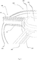
- the cutter holder 200 required for the installation of the cutters in question appears as a radial structure in which a plurality of radial arms 203 - that terminate in a perimeter circular crown 204, concentric to said central metal body 202 - depart from a central metal body 202, provided with a central hole 201 suitable to be connected to the driving shaft of the entire plant.
- each of said radial arms 203 is provided with a housing seat 205 constituted by a longitudinal direction fissure configured to enable the reversible housing of a corresponding cutter 100 like the one described hereinafter.
- said housing seat 205 will be arranged in proximity of said perimeter circular crown 204 and, possibly, the radial arm 203 shall be provided, at said seat 205, with common mechanical means such as screws, pins or the like, for stably but reversibly fixing the cutter 100, in the correct operating position.
- the dimensioning of said seat 205 must consider the total dimensions of the cutter 100 intended to be utilised in the plant.
- said cutter 100 will in any case be inscribed in a parallelepiped shaped element with dimensions measured between 30 mm X 15 mm X 3 mm and 90 mm X 30 mm X 10 mm.
- the components of said cutter 100 are represented by a first T-shaped element 10 and a second C-shaped element 20.
- Said first element 10 is constituted by an outer sharp profile 11 and by a central projection 15 provided, laterally, with a pair of concavities 16-16'.
- Said second element 20 is constituted by an outer sharp profile 21 and by a pair of bending arms 26-26' provided, at the relative distal ends, with a convexity 27-27'. Said bending arms 26-26', departing from the lateral ends of the second element 20 extending towards the centre, confer the aforementioned "C" shape to said second element 20.
- first element 10 and said second element 20 of the cutter 100 are suitable to be mutually and reversibly engaged in a first assembled configuration, in which the convexities 27-27' of the two bending arms 26-26' are reversibly but stably lodged in the corresponding cavities 16-16' of the first element 10.
- the fissures 30 that are created when said cutter 100 is in said first assembled configuration are characterised by a thickness comprised between 0.2 mm and 3 mm, preferably 1 mm.
- the latter have the advantageous function of enabling the bending of the bending arms 26-26' due to the pressure caused by the resistance of the meat to be minced.
- the strong pressure exerted by the meat deforms the fixed disc arranged upstream of the cutter holder 200. Pressure and temperatures high enough to melt the metal and release part thereof into the minced meat would occur were the cutters 100 to be completely rigid.
- the elasticity of the cutter 100 has the function of adapting to the deformations that occur during operation, thus guaranteeing an optimal quality of the meat and the cutting efficiency.
- the length of the bending arms 26-26' be equivalent to about 1 ⁇ 4 of the overall length of the cutter 100.
- composition of the first and the second element 10, 20 in said first assembled configuration may occur using common mechanical means, such as, for example, a gripper, so that the bending arms 26-26' are pre-loaded with a pre-established tension.
- the cutter 100 it is constituted of be made of any metal or metal alloy, preferably any elastic metal material.
- the first and the second element 10, 20 can be disassembled in a quick, easy and reversible manner so as to confer a second disassembled configuration to the cutter 100.
- the cutter 100 maintenance and cleaning operations are advantageously simplified.
- the cutter 100 in question reveals an elastic behaviour under the action of strong mechanical stresses, thus serving the purpose of the invention even for a long period of operation.
- this cutter holder 200 is provided with a central metal body 202 provided with a central hole 201 through which the plant driving shaft that transmits motion to all rotary parts of the plant itself passes.
- the distinctive trait of this cutter holder 200 with respect to the currently available ones lies in that each of the radial arms 203, in proximity of said perimeter crown 204, has a seat 205 for housing a cutter 100 of the present invention.
- the cutter 100 of the present invention will always be inscribed in a parallelepiped shaped element with dimensions measured between 30 mm X 15 mm X 3 mm and 90 mm X 30 mm X 10 mm.
- the configuration of the plant provides stability to the position of the cutter 100 with respect to the cutter holder 200, given the vicinity of the extrusion fixed discs arranged both upstream and downstream of the cutter holder 200.
- every radial arm 203 may be provided, at said seat 205, with common mechanical means such as screws, pins or the like, for fixing the cutter 100 stably but reversibly.
- the cutter 100 represented in the cutter holder 200, still with reference to FIG. 2 is the same one represented in detail in FIGS. 1A and 1B .
- the cutter 100 in question is made up of two components that are reversibly and easily modulable.
- the first element 10 is T-shaped and it is constituted by an outer sharp profile 11 and a central projection 15 provided, laterally, with a pair of concavities 16-16', one to the right and one to the left of said central projection 15.
- the second element 20 is C-shaped and it is constituted by an outer sharp profile 21 and by a pair of bending arms 26-26' provided, at the relative distal ends, with a convexity 27-27'. Said bending arms 26-26', depart from the ends and extend towards the centre of the cutter 100, conferring the aforementioned "C" shape to said second element 20.
- FIG. 1B enables to easily understand the composition of said elements 10, 20 in an assembled configuration in which the latter are engaged mutually and reversibly.
- the metal or metal alloy material selected to obtain the cutter 100 be an elastic metal material.
- fissures 30 between the sharp profile 11 of the first element 10 and the bending arms 26-26' occur when the cutter 100 is in assembled configuration.
- Such fissures 30 are suitable to enable the bending of said bending arms 26-26' due to the pressure caused by the resistance of the meat to be minced.
- the bending of the cutters 100 is actually the characteristic that prevents the release of metal parts into the meat, by avoiding excessive friction between the components of the plant and thus attaining the object of the invention.
- the thickness of said fissures 30' will be comprised between 0.2 mm and 3 mm, preferably equivalent to 1 mm.
- the particular configuration of the cutter 100 of the present invention is such to make the use thereof advantageous for producing sausages, but more in particular advantageous for producing salamis.
Landscapes
- Engineering & Computer Science (AREA)
- Food Science & Technology (AREA)
- Life Sciences & Earth Sciences (AREA)
- Wood Science & Technology (AREA)
- Zoology (AREA)
- Meat, Egg Or Seafood Products (AREA)
- Organic Low-Molecular-Weight Compounds And Preparation Thereof (AREA)
Claims (9)
- Reversibles modulares elastisches Schneidelement (100) zum Herstellen von Salamis, das geeignet ist, mit dem radialen Arm (203) eines Schneidelementhalters (200) reversibel in Eingriff gebracht zu werden und während des Schrittes des Schneidens / Zerkleinerns von Tierfleisch in einer industriellen Wurstproduktionsanlage verwendet zu werden; wobei das Schneidelement (100) dadurch gekennzeichnet ist, dass es aus mindestens einem ersten T-förmigen Element (10) und einem zweiten C-förmigen Element (20) besteht, wobei das erste Element (10) aus einem äußeren scharfen Profil (11) und einem zentralen Vorsprung (15) besteht, der seitlich mit einem Paar von Konkavitäten (16-16') versehen ist; wobei das zweite Element (20) aus einem äußeren scharfen Profil (21) und einem Paar von Biegearmen (26-26') besteht, die - an den relativen distalen Enden - mit einer Konvexität (27-27') versehen sind; wobei die Elemente (10, 20) geeignet sind, in einer ersten zusammengebauten Konfiguration gegenseitig und reversibel in Eingriff gebracht zu werden, wobei die Konvexitäten (27-27') der beiden Biegearme (26-26') des zweiten Elements (20) reversibel aber stabil in die entsprechenden Konkavitäten (16-16') des ersten Elements (10) gekoppelt sind; wobei die erste zusammengebaute Konfiguration mit einer solchen Konfiguration versehen ist, dass sie den Biegearmen (26-26') eine vorbestimmte Zugbelastung verleiht; wobei das Schneidelement (100), wenn es sich in der ersten zusammengebauten Konfiguration befindet, geeignet ist, reversibel in einen speziellen Sitz (205) eingesetzt zu werden, der an jedem der radialen Arme (203) angeordnet ist, die den Schneidelementhalter (200) der industriellen Fleischproduktionsanlage bilden; wobei das Schneidelement (100)s, wenn es aus dem Schneidelementhalter (200) entfernt wird, auch geeignet ist, schnell und einfach eine zweite demontierte Konfiguration anzunehmen, wobei das erste Element (10) und das zweite Element (20) voneinander getrennt sind, um seine Reinigung und Wartung zu ermöglichen.
- Reversibles modulares elastisches Schneidelement (100) zum Herstellen von Salamis gemäß Anspruch 1, dadurch gekennzeichnet, dass, wenn es sich in der ersten zusammengebauten Konfiguration befindet, zwischen dem scharfen Profil (11) des ersten Elements (10) und den Biegearmen (26-26'), zwischen den Biegearmen (26-26') und dem scharfen Profil (21) des zweiten Elements (20) mehrere Spalte (30) erzeugt werden, die geeignet sind, das Biegen der Biegearme (26-26') zu erlauben, d.h.: wenn das zu zerkleinernde Fleisch die feste Scheibe stromaufwärts drückt und verformt, nimmt sie eine kegelstumpfförmige Form an, und das Schneidelement (100) verformt sich, wobei es einen Teil der durch das Fleisch ausgeübten Verformung absorbiert, wodurch Spitzenbelastungen, die zu unerwünschtem Verschleiß führen könnten, vermieden werden.
- Reversibles modulares elastisches Schneidelement (100) zum Herstellen von Salamis gemäß Anspruch 2, dadurch gekennzeichnet, dass die Dicke der Spalten (30) zwischen 0,2 mm und 3 mm, vorzugsweise 1 mm, beträgt.
- Reversibles modulares elastisches Schneidelement (100) zum Herstellen von Salamis gemäß einem der vorhergehenden Ansprüche, dadurch gekennzeichnet, dass das erste Element (10) und das zweite Element (20) in der ersten zusammengebauten Konfiguration und in der zweiten auseinandergenommenen Konfiguration unter Verwendung gewöhnlicher mechanischer Mittel wie beispielsweise Greifer, die ein Vorbelasten der Biegearme (26-26') ermöglichen, reversibel zusammengebaut und auseinandergenommen werden können.
- Reversibles modulares elastisches Schneidelement (100) zum Herstellen von Salamis gemäß einem der vorangehenden Ansprüche, dadurch gekennzeichnet, dass es reversibel an einem der radialen Arme (203) eines gewöhnlichen Schneidelementhalters (200) in Eingriff steht, wobei letzterer aus einem zentralen Metallkörper (202) besteht, der mit einem zentralen Loch (201) versehen ist, von dem mehrere radiale Arme (203) ausgehen, die in einer kreisförmigen, zu dem zentralen Metallkörper (202) konzentrischen Umfangskrone (204) enden; wobei jeder der radialen Arme (203) durch einen Aufnahmesitz (205) gekennzeichnet ist, der durch einen länglichen Spalt gebildet wird, die in der Nähe der kreisförmigen Umfangskrone (204) angeordnet und geeignet dimensioniert ist, um in der ersten zusammengebauten Konfiguration mit einem der Schneidelemente (100) in Eingriff gebracht zu werden.
- Reversibles modulares elastisches Schneidelement (100) zum Herstellen von Salamis gemäß Anspruch 5, dadurch gekennzeichnet, dass der radiale Arm (203) an dem Sitz (205) mit gewöhnlichen mechanischen Mitteln wie Schrauben, Stiften oder dergleichen versehen werden kann, um das Schneidelement (100) stabil aber reversibel an dem entsprechenden Sitz (205) zu befestigen.
- Reversibles modulares elastisches Schneidelement (100) zum Herstellen von Salamis gemäß einem der vorangehenden Ansprüche, dadurch gekennzeichnet, dass es in der ersten zusammengebauten Konfiguration in ein parallelepipedförmiges Element mit Abmessungen zwischen 30 mm x 15 mm x 3 mm und 90 mm x 30 mm x 10 mm eingeschrieben werden kann.
- Reversibles modulares elastisches Schneidelement (100) zum Herstellen von Salamis gemäß einem der vorhergehenden Ansprüche, dadurch gekennzeichnet, dass die Biegearme (26-26') mit einer Längsausdehnung versehen sind, die etwa ¼ der Gesamtlänge des Schneidelements (100, 100') entspricht.
- Reversibles modulares elastisches Schneidelement (100) zum Herstellen von Salamis gemäß einem der vorangehenden Ansprüche, dadurch gekennzeichnet, dass es aus einem beliebigen Metall oder einer beliebigen Metalllegierung, vorzugsweise einem beliebigen elastischen Metallmaterial, besteht.
Applications Claiming Priority (2)
| Application Number | Priority Date | Filing Date | Title |
|---|---|---|---|
| IT102016000073507A IT201600073507A1 (it) | 2016-07-14 | 2016-07-14 | Coltello elastico reversibilmente componibile per la produzione di salame. |
| PCT/IB2017/054202 WO2018011726A1 (en) | 2016-07-14 | 2017-07-12 | Reversibly modular elastic cutter for producing salamis |
Publications (2)
| Publication Number | Publication Date |
|---|---|
| EP3484300A1 EP3484300A1 (de) | 2019-05-22 |
| EP3484300B1 true EP3484300B1 (de) | 2020-08-26 |
Family
ID=57708657
Family Applications (1)
| Application Number | Title | Priority Date | Filing Date |
|---|---|---|---|
| EP17749533.0A Active EP3484300B1 (de) | 2016-07-14 | 2017-07-12 | Reversibles modulares elastisches schneidelement zur herstellung von salami |
Country Status (3)
| Country | Link |
|---|---|
| EP (1) | EP3484300B1 (de) |
| IT (1) | IT201600073507A1 (de) |
| WO (1) | WO2018011726A1 (de) |
Families Citing this family (5)
| Publication number | Priority date | Publication date | Assignee | Title |
|---|---|---|---|---|
| EP3669658A1 (de) * | 2018-12-21 | 2020-06-24 | Marel Salmon A/S | Lebensmittelverarbeitungsvorrichtung, messersatz für eine lebensmittelverarbeitungsvorrichtung sowie verfahren zum schärfen eines messers für eine lebensmittelverarbeitungsvorrichtung |
| CA3041215A1 (en) * | 2019-03-18 | 2020-09-18 | Cozzini Llc | Emulsification system |
| MX2021011332A (es) | 2019-03-18 | 2021-10-13 | Cozzini Llc | Sistema de emulsificacion. |
| IT202000012163A1 (it) * | 2020-05-25 | 2021-11-25 | Evolution’S Di Rico Lucelly Maria | Coltello a lama mobile per il taglio di carne macinata |
| US12465898B2 (en) | 2022-03-31 | 2025-11-11 | Cozzini Llc | Emulsification system |
Family Cites Families (6)
| Publication number | Priority date | Publication date | Assignee | Title |
|---|---|---|---|---|
| ITBO20030700A1 (it) * | 2003-11-21 | 2005-05-22 | Marcello Quadrana | Perfezionamenti apportati al gruppo di taglio per unita' macinante. |
| DE102008019812A1 (de) * | 2008-04-19 | 2009-10-22 | Turbocut Jopp Gmbh | Wolfmesser mit eingesetzten Klingen |
| US8257148B1 (en) * | 2009-01-06 | 2012-09-04 | Reliance Controls Corporation | Knife insert with bottom edge relief for cutting edge alignment |
| IT1403529B1 (it) * | 2011-01-26 | 2013-10-31 | Quadrana | Perfezionamenti per un gruppo di taglio di unita' macinante. |
| ITRM20130196A1 (it) | 2013-04-03 | 2014-10-04 | Evoluzione Srl | Dispositivo di taglio. |
| ITRM20130193A1 (it) | 2013-04-03 | 2014-10-04 | Evoluzione Srl | Girante portacoltelli con coltelli perfezionati, per una macchina di lavorazione della carne di maiale, in particolare per produrre la mortadella o altri insaccati. |
-
2016
- 2016-07-14 IT IT102016000073507A patent/IT201600073507A1/it unknown
-
2017
- 2017-07-12 WO PCT/IB2017/054202 patent/WO2018011726A1/en not_active Ceased
- 2017-07-12 EP EP17749533.0A patent/EP3484300B1/de active Active
Non-Patent Citations (1)
| Title |
|---|
| None * |
Also Published As
| Publication number | Publication date |
|---|---|
| EP3484300A1 (de) | 2019-05-22 |
| WO2018011726A1 (en) | 2018-01-18 |
| IT201600073507A1 (it) | 2018-01-14 |
Similar Documents
| Publication | Publication Date | Title |
|---|---|---|
| WO2018011726A1 (en) | Reversibly modular elastic cutter for producing salamis | |
| EP3484302B1 (de) | Reversibles modulares elastisches schneidelement zur herstellung von wurst | |
| US4068008A (en) | Food product extrusion apparatus and method | |
| US4205415A (en) | Food product extrusion apparatus | |
| EP3119208B1 (de) | Verbesserte antireibungsvorrichtung für metalloberflächen | |
| JP2019068839A (ja) | 粘着性材料を加熱又は冷却するための方法及びデバイス | |
| CA2051919A1 (en) | Food slicing with multiple cutting surface blade | |
| EP3582620B1 (de) | Schneidvorrichtung mit monolithischer struktur | |
| AU628730B2 (en) | Cutting process | |
| WO2014162222A1 (en) | Knife-holder rotor with improved knives, for a machine for processing swine meat, in particular for producing mortadella or other sausages | |
| EP0914208B1 (de) | Ausgabeplatte für einen nahrungsmittelautomaten | |
| WO2018011728A1 (en) | Cutting device | |
| KR101243979B1 (ko) | 칼날의 경사각과 간격을 이용한 생육, 생선, 홍어의 세절 방법 | |
| WO2014162225A1 (en) | Cutting device | |
| CA2952262A1 (en) | Meat slicer with improved safety feature | |
| WO2015140673A1 (en) | Metal surfaces anti-rub apparatus | |
| EP3484301B1 (de) | Reversibler lösbarer und waschbarer fester querträger | |
| IT202000012163A1 (it) | Coltello a lama mobile per il taglio di carne macinata | |
| US2737684A (en) | Meat treating mechanism | |
| KR102421612B1 (ko) | 칼날의 교차왕복운동을 이용한 세절기 | |
| US1157016A (en) | Process for preparing foods. | |
| WO2018011724A1 (en) | Reversibly removable and washable fixed crosspiece | |
| CN206812057U (zh) | 一种食品切刀 | |
| KR102377831B1 (ko) | 칼날의 교차왕복운동을 이용한 세절기 | |
| WO2018145131A8 (en) | Cross cut tenderizer |
Legal Events
| Date | Code | Title | Description |
|---|---|---|---|
| STAA | Information on the status of an ep patent application or granted ep patent |
Free format text: STATUS: UNKNOWN |
|
| STAA | Information on the status of an ep patent application or granted ep patent |
Free format text: STATUS: THE INTERNATIONAL PUBLICATION HAS BEEN MADE |
|
| PUAI | Public reference made under article 153(3) epc to a published international application that has entered the european phase |
Free format text: ORIGINAL CODE: 0009012 |
|
| STAA | Information on the status of an ep patent application or granted ep patent |
Free format text: STATUS: REQUEST FOR EXAMINATION WAS MADE |
|
| 17P | Request for examination filed |
Effective date: 20190129 |
|
| AK | Designated contracting states |
Kind code of ref document: A1 Designated state(s): AL AT BE BG CH CY CZ DE DK EE ES FI FR GB GR HR HU IE IS IT LI LT LU LV MC MK MT NL NO PL PT RO RS SE SI SK SM TR |
|
| AX | Request for extension of the european patent |
Extension state: BA ME |
|
| DAV | Request for validation of the european patent (deleted) | ||
| GRAP | Despatch of communication of intention to grant a patent |
Free format text: ORIGINAL CODE: EPIDOSNIGR1 |
|
| STAA | Information on the status of an ep patent application or granted ep patent |
Free format text: STATUS: GRANT OF PATENT IS INTENDED |
|
| INTG | Intention to grant announced |
Effective date: 20200319 |
|
| GRAS | Grant fee paid |
Free format text: ORIGINAL CODE: EPIDOSNIGR3 |
|
| GRAA | (expected) grant |
Free format text: ORIGINAL CODE: 0009210 |
|
| STAA | Information on the status of an ep patent application or granted ep patent |
Free format text: STATUS: THE PATENT HAS BEEN GRANTED |
|
| AK | Designated contracting states |
Kind code of ref document: B1 Designated state(s): AL AT BE BG CH CY CZ DE DK EE ES FI FR GB GR HR HU IE IS IT LI LT LU LV MC MK MT NL NO PL PT RO RS SE SI SK SM TR |
|
| AX | Request for extension of the european patent |
Extension state: BA ME |
|
| REG | Reference to a national code |
Ref country code: GB Ref legal event code: FG4D |
|
| REG | Reference to a national code |
Ref country code: CH Ref legal event code: EP |
|
| REG | Reference to a national code |
Ref country code: DE Ref legal event code: R096 Ref document number: 602017022406 Country of ref document: DE |
|
| REG | Reference to a national code |
Ref country code: AT Ref legal event code: REF Ref document number: 1305483 Country of ref document: AT Kind code of ref document: T Effective date: 20200915 |
|
| REG | Reference to a national code |
Ref country code: IE Ref legal event code: FG4D |
|
| REG | Reference to a national code |
Ref country code: LT Ref legal event code: MG4D |
|
| PG25 | Lapsed in a contracting state [announced via postgrant information from national office to epo] |
Ref country code: GR Free format text: LAPSE BECAUSE OF FAILURE TO SUBMIT A TRANSLATION OF THE DESCRIPTION OR TO PAY THE FEE WITHIN THE PRESCRIBED TIME-LIMIT Effective date: 20201127 Ref country code: FI Free format text: LAPSE BECAUSE OF FAILURE TO SUBMIT A TRANSLATION OF THE DESCRIPTION OR TO PAY THE FEE WITHIN THE PRESCRIBED TIME-LIMIT Effective date: 20200826 Ref country code: BG Free format text: LAPSE BECAUSE OF FAILURE TO SUBMIT A TRANSLATION OF THE DESCRIPTION OR TO PAY THE FEE WITHIN THE PRESCRIBED TIME-LIMIT Effective date: 20201126 Ref country code: NO Free format text: LAPSE BECAUSE OF FAILURE TO SUBMIT A TRANSLATION OF THE DESCRIPTION OR TO PAY THE FEE WITHIN THE PRESCRIBED TIME-LIMIT Effective date: 20201126 Ref country code: SE Free format text: LAPSE BECAUSE OF FAILURE TO SUBMIT A TRANSLATION OF THE DESCRIPTION OR TO PAY THE FEE WITHIN THE PRESCRIBED TIME-LIMIT Effective date: 20200826 Ref country code: HR Free format text: LAPSE BECAUSE OF FAILURE TO SUBMIT A TRANSLATION OF THE DESCRIPTION OR TO PAY THE FEE WITHIN THE PRESCRIBED TIME-LIMIT Effective date: 20200826 Ref country code: PT Free format text: LAPSE BECAUSE OF FAILURE TO SUBMIT A TRANSLATION OF THE DESCRIPTION OR TO PAY THE FEE WITHIN THE PRESCRIBED TIME-LIMIT Effective date: 20201228 Ref country code: LT Free format text: LAPSE BECAUSE OF FAILURE TO SUBMIT A TRANSLATION OF THE DESCRIPTION OR TO PAY THE FEE WITHIN THE PRESCRIBED TIME-LIMIT Effective date: 20200826 |
|
| REG | Reference to a national code |
Ref country code: NL Ref legal event code: MP Effective date: 20200826 |
|
| REG | Reference to a national code |
Ref country code: AT Ref legal event code: MK05 Ref document number: 1305483 Country of ref document: AT Kind code of ref document: T Effective date: 20200826 |
|
| PG25 | Lapsed in a contracting state [announced via postgrant information from national office to epo] |
Ref country code: PL Free format text: LAPSE BECAUSE OF FAILURE TO SUBMIT A TRANSLATION OF THE DESCRIPTION OR TO PAY THE FEE WITHIN THE PRESCRIBED TIME-LIMIT Effective date: 20200826 Ref country code: NL Free format text: LAPSE BECAUSE OF FAILURE TO SUBMIT A TRANSLATION OF THE DESCRIPTION OR TO PAY THE FEE WITHIN THE PRESCRIBED TIME-LIMIT Effective date: 20200826 Ref country code: LV Free format text: LAPSE BECAUSE OF FAILURE TO SUBMIT A TRANSLATION OF THE DESCRIPTION OR TO PAY THE FEE WITHIN THE PRESCRIBED TIME-LIMIT Effective date: 20200826 Ref country code: RS Free format text: LAPSE BECAUSE OF FAILURE TO SUBMIT A TRANSLATION OF THE DESCRIPTION OR TO PAY THE FEE WITHIN THE PRESCRIBED TIME-LIMIT Effective date: 20200826 Ref country code: IS Free format text: LAPSE BECAUSE OF FAILURE TO SUBMIT A TRANSLATION OF THE DESCRIPTION OR TO PAY THE FEE WITHIN THE PRESCRIBED TIME-LIMIT Effective date: 20201226 |
|
| PG25 | Lapsed in a contracting state [announced via postgrant information from national office to epo] |
Ref country code: CZ Free format text: LAPSE BECAUSE OF FAILURE TO SUBMIT A TRANSLATION OF THE DESCRIPTION OR TO PAY THE FEE WITHIN THE PRESCRIBED TIME-LIMIT Effective date: 20200826 Ref country code: DK Free format text: LAPSE BECAUSE OF FAILURE TO SUBMIT A TRANSLATION OF THE DESCRIPTION OR TO PAY THE FEE WITHIN THE PRESCRIBED TIME-LIMIT Effective date: 20200826 Ref country code: RO Free format text: LAPSE BECAUSE OF FAILURE TO SUBMIT A TRANSLATION OF THE DESCRIPTION OR TO PAY THE FEE WITHIN THE PRESCRIBED TIME-LIMIT Effective date: 20200826 Ref country code: EE Free format text: LAPSE BECAUSE OF FAILURE TO SUBMIT A TRANSLATION OF THE DESCRIPTION OR TO PAY THE FEE WITHIN THE PRESCRIBED TIME-LIMIT Effective date: 20200826 Ref country code: SM Free format text: LAPSE BECAUSE OF FAILURE TO SUBMIT A TRANSLATION OF THE DESCRIPTION OR TO PAY THE FEE WITHIN THE PRESCRIBED TIME-LIMIT Effective date: 20200826 |
|
| REG | Reference to a national code |
Ref country code: DE Ref legal event code: R097 Ref document number: 602017022406 Country of ref document: DE |
|
| PG25 | Lapsed in a contracting state [announced via postgrant information from national office to epo] |
Ref country code: AL Free format text: LAPSE BECAUSE OF FAILURE TO SUBMIT A TRANSLATION OF THE DESCRIPTION OR TO PAY THE FEE WITHIN THE PRESCRIBED TIME-LIMIT Effective date: 20200826 Ref country code: AT Free format text: LAPSE BECAUSE OF FAILURE TO SUBMIT A TRANSLATION OF THE DESCRIPTION OR TO PAY THE FEE WITHIN THE PRESCRIBED TIME-LIMIT Effective date: 20200826 Ref country code: ES Free format text: LAPSE BECAUSE OF FAILURE TO SUBMIT A TRANSLATION OF THE DESCRIPTION OR TO PAY THE FEE WITHIN THE PRESCRIBED TIME-LIMIT Effective date: 20200826 |
|
| PG25 | Lapsed in a contracting state [announced via postgrant information from national office to epo] |
Ref country code: SK Free format text: LAPSE BECAUSE OF FAILURE TO SUBMIT A TRANSLATION OF THE DESCRIPTION OR TO PAY THE FEE WITHIN THE PRESCRIBED TIME-LIMIT Effective date: 20200826 |
|
| PLBE | No opposition filed within time limit |
Free format text: ORIGINAL CODE: 0009261 |
|
| STAA | Information on the status of an ep patent application or granted ep patent |
Free format text: STATUS: NO OPPOSITION FILED WITHIN TIME LIMIT |
|
| PG25 | Lapsed in a contracting state [announced via postgrant information from national office to epo] |
Ref country code: IT Free format text: LAPSE BECAUSE OF FAILURE TO SUBMIT A TRANSLATION OF THE DESCRIPTION OR TO PAY THE FEE WITHIN THE PRESCRIBED TIME-LIMIT Effective date: 20200826 |
|
| 26N | No opposition filed |
Effective date: 20210527 |
|
| PG25 | Lapsed in a contracting state [announced via postgrant information from national office to epo] |
Ref country code: SI Free format text: LAPSE BECAUSE OF FAILURE TO SUBMIT A TRANSLATION OF THE DESCRIPTION OR TO PAY THE FEE WITHIN THE PRESCRIBED TIME-LIMIT Effective date: 20200826 |
|
| REG | Reference to a national code |
Ref country code: CH Ref legal event code: PL |
|
| PG25 | Lapsed in a contracting state [announced via postgrant information from national office to epo] |
Ref country code: MC Free format text: LAPSE BECAUSE OF FAILURE TO SUBMIT A TRANSLATION OF THE DESCRIPTION OR TO PAY THE FEE WITHIN THE PRESCRIBED TIME-LIMIT Effective date: 20200826 |
|
| REG | Reference to a national code |
Ref country code: BE Ref legal event code: MM Effective date: 20210731 |
|
| PG25 | Lapsed in a contracting state [announced via postgrant information from national office to epo] |
Ref country code: LI Free format text: LAPSE BECAUSE OF NON-PAYMENT OF DUE FEES Effective date: 20210731 Ref country code: CH Free format text: LAPSE BECAUSE OF NON-PAYMENT OF DUE FEES Effective date: 20210731 |
|
| PG25 | Lapsed in a contracting state [announced via postgrant information from national office to epo] |
Ref country code: LU Free format text: LAPSE BECAUSE OF NON-PAYMENT OF DUE FEES Effective date: 20210712 |
|
| PG25 | Lapsed in a contracting state [announced via postgrant information from national office to epo] |
Ref country code: IE Free format text: LAPSE BECAUSE OF NON-PAYMENT OF DUE FEES Effective date: 20210712 Ref country code: BE Free format text: LAPSE BECAUSE OF NON-PAYMENT OF DUE FEES Effective date: 20210731 |
|
| PGFP | Annual fee paid to national office [announced via postgrant information from national office to epo] |
Ref country code: FR Payment date: 20230130 Year of fee payment: 6 |
|
| PGFP | Annual fee paid to national office [announced via postgrant information from national office to epo] |
Ref country code: GB Payment date: 20230130 Year of fee payment: 6 |
|
| PG25 | Lapsed in a contracting state [announced via postgrant information from national office to epo] |
Ref country code: CY Free format text: LAPSE BECAUSE OF FAILURE TO SUBMIT A TRANSLATION OF THE DESCRIPTION OR TO PAY THE FEE WITHIN THE PRESCRIBED TIME-LIMIT Effective date: 20200826 |
|
| PG25 | Lapsed in a contracting state [announced via postgrant information from national office to epo] |
Ref country code: HU Free format text: LAPSE BECAUSE OF FAILURE TO SUBMIT A TRANSLATION OF THE DESCRIPTION OR TO PAY THE FEE WITHIN THE PRESCRIBED TIME-LIMIT; INVALID AB INITIO Effective date: 20170712 |
|
| GBPC | Gb: european patent ceased through non-payment of renewal fee |
Effective date: 20230712 |
|
| PG25 | Lapsed in a contracting state [announced via postgrant information from national office to epo] |
Ref country code: MK Free format text: LAPSE BECAUSE OF FAILURE TO SUBMIT A TRANSLATION OF THE DESCRIPTION OR TO PAY THE FEE WITHIN THE PRESCRIBED TIME-LIMIT Effective date: 20200826 Ref country code: GB Free format text: LAPSE BECAUSE OF NON-PAYMENT OF DUE FEES Effective date: 20230712 |
|
| PG25 | Lapsed in a contracting state [announced via postgrant information from national office to epo] |
Ref country code: FR Free format text: LAPSE BECAUSE OF NON-PAYMENT OF DUE FEES Effective date: 20230731 |
|
| PG25 | Lapsed in a contracting state [announced via postgrant information from national office to epo] |
Ref country code: MT Free format text: LAPSE BECAUSE OF FAILURE TO SUBMIT A TRANSLATION OF THE DESCRIPTION OR TO PAY THE FEE WITHIN THE PRESCRIBED TIME-LIMIT Effective date: 20200826 |
|
| REG | Reference to a national code |
Ref country code: DE Ref legal event code: R081 Ref document number: 602017022406 Country of ref document: DE Owner name: BEDESCHI SALUMI S.R.L., BENTIVOGLIO, IT Free format text: FORMER OWNER: QUADRANA, MARCELLO, ZOLA PREDOSA, BOLOGNA, IT |
|
| PGFP | Annual fee paid to national office [announced via postgrant information from national office to epo] |
Ref country code: DE Payment date: 20250729 Year of fee payment: 9 |
|
| PG25 | Lapsed in a contracting state [announced via postgrant information from national office to epo] |
Ref country code: TR Free format text: LAPSE BECAUSE OF FAILURE TO SUBMIT A TRANSLATION OF THE DESCRIPTION OR TO PAY THE FEE WITHIN THE PRESCRIBED TIME-LIMIT Effective date: 20200826 |