EP3483980A1 - Batteriemodul mit einfacher sensorstruktur - Google Patents
Batteriemodul mit einfacher sensorstruktur Download PDFInfo
- Publication number
- EP3483980A1 EP3483980A1 EP18772425.7A EP18772425A EP3483980A1 EP 3483980 A1 EP3483980 A1 EP 3483980A1 EP 18772425 A EP18772425 A EP 18772425A EP 3483980 A1 EP3483980 A1 EP 3483980A1
- Authority
- EP
- European Patent Office
- Prior art keywords
- sensing
- battery cell
- lead
- electrode
- pouch
- Prior art date
- Legal status (The legal status is an assumption and is not a legal conclusion. Google has not performed a legal analysis and makes no representation as to the accuracy of the status listed.)
- Granted
Links
Images


Classifications
-
- H—ELECTRICITY
- H01—ELECTRIC ELEMENTS
- H01M—PROCESSES OR MEANS, e.g. BATTERIES, FOR THE DIRECT CONVERSION OF CHEMICAL ENERGY INTO ELECTRICAL ENERGY
- H01M10/00—Secondary cells; Manufacture thereof
- H01M10/42—Methods or arrangements for servicing or maintenance of secondary cells or secondary half-cells
- H01M10/48—Accumulators combined with arrangements for measuring, testing or indicating the condition of cells, e.g. the level or density of the electrolyte
-
- H—ELECTRICITY
- H01—ELECTRIC ELEMENTS
- H01M—PROCESSES OR MEANS, e.g. BATTERIES, FOR THE DIRECT CONVERSION OF CHEMICAL ENERGY INTO ELECTRICAL ENERGY
- H01M50/00—Constructional details or processes of manufacture of the non-active parts of electrochemical cells other than fuel cells, e.g. hybrid cells
- H01M50/10—Primary casings; Jackets or wrappings
- H01M50/102—Primary casings; Jackets or wrappings characterised by their shape or physical structure
- H01M50/105—Pouches or flexible bags
-
- H—ELECTRICITY
- H01—ELECTRIC ELEMENTS
- H01M—PROCESSES OR MEANS, e.g. BATTERIES, FOR THE DIRECT CONVERSION OF CHEMICAL ENERGY INTO ELECTRICAL ENERGY
- H01M50/00—Constructional details or processes of manufacture of the non-active parts of electrochemical cells other than fuel cells, e.g. hybrid cells
- H01M50/20—Mountings; Secondary casings or frames; Racks, modules or packs; Suspension devices; Shock absorbers; Transport or carrying devices; Holders
- H01M50/204—Racks, modules or packs for multiple batteries or multiple cells
- H01M50/207—Racks, modules or packs for multiple batteries or multiple cells characterised by their shape
- H01M50/211—Racks, modules or packs for multiple batteries or multiple cells characterised by their shape adapted for pouch cells
-
- H—ELECTRICITY
- H01—ELECTRIC ELEMENTS
- H01M—PROCESSES OR MEANS, e.g. BATTERIES, FOR THE DIRECT CONVERSION OF CHEMICAL ENERGY INTO ELECTRICAL ENERGY
- H01M50/00—Constructional details or processes of manufacture of the non-active parts of electrochemical cells other than fuel cells, e.g. hybrid cells
- H01M50/20—Mountings; Secondary casings or frames; Racks, modules or packs; Suspension devices; Shock absorbers; Transport or carrying devices; Holders
- H01M50/258—Modular batteries; Casings provided with means for assembling
-
- H—ELECTRICITY
- H01—ELECTRIC ELEMENTS
- H01M—PROCESSES OR MEANS, e.g. BATTERIES, FOR THE DIRECT CONVERSION OF CHEMICAL ENERGY INTO ELECTRICAL ENERGY
- H01M50/00—Constructional details or processes of manufacture of the non-active parts of electrochemical cells other than fuel cells, e.g. hybrid cells
- H01M50/50—Current conducting connections for cells or batteries
- H01M50/531—Electrode connections inside a battery casing
- H01M50/536—Electrode connections inside a battery casing characterised by the method of fixing the leads to the electrodes, e.g. by welding
-
- H—ELECTRICITY
- H01—ELECTRIC ELEMENTS
- H01M—PROCESSES OR MEANS, e.g. BATTERIES, FOR THE DIRECT CONVERSION OF CHEMICAL ENERGY INTO ELECTRICAL ENERGY
- H01M50/00—Constructional details or processes of manufacture of the non-active parts of electrochemical cells other than fuel cells, e.g. hybrid cells
- H01M50/50—Current conducting connections for cells or batteries
- H01M50/543—Terminals
- H01M50/547—Terminals characterised by the disposition of the terminals on the cells
- H01M50/548—Terminals characterised by the disposition of the terminals on the cells on opposite sides of the cell
-
- H—ELECTRICITY
- H01—ELECTRIC ELEMENTS
- H01M—PROCESSES OR MEANS, e.g. BATTERIES, FOR THE DIRECT CONVERSION OF CHEMICAL ENERGY INTO ELECTRICAL ENERGY
- H01M50/00—Constructional details or processes of manufacture of the non-active parts of electrochemical cells other than fuel cells, e.g. hybrid cells
- H01M50/50—Current conducting connections for cells or batteries
- H01M50/543—Terminals
- H01M50/552—Terminals characterised by their shape
- H01M50/553—Terminals adapted for prismatic, pouch or rectangular cells
-
- H—ELECTRICITY
- H01—ELECTRIC ELEMENTS
- H01M—PROCESSES OR MEANS, e.g. BATTERIES, FOR THE DIRECT CONVERSION OF CHEMICAL ENERGY INTO ELECTRICAL ENERGY
- H01M50/00—Constructional details or processes of manufacture of the non-active parts of electrochemical cells other than fuel cells, e.g. hybrid cells
- H01M50/50—Current conducting connections for cells or batteries
- H01M50/569—Constructional details of current conducting connections for detecting conditions inside cells or batteries, e.g. details of voltage sensing terminals
-
- H—ELECTRICITY
- H01—ELECTRIC ELEMENTS
- H01M—PROCESSES OR MEANS, e.g. BATTERIES, FOR THE DIRECT CONVERSION OF CHEMICAL ENERGY INTO ELECTRICAL ENERGY
- H01M50/00—Constructional details or processes of manufacture of the non-active parts of electrochemical cells other than fuel cells, e.g. hybrid cells
- H01M50/10—Primary casings; Jackets or wrappings
- H01M50/116—Primary casings; Jackets or wrappings characterised by the material
- H01M50/117—Inorganic material
- H01M50/119—Metals
-
- H—ELECTRICITY
- H01—ELECTRIC ELEMENTS
- H01M—PROCESSES OR MEANS, e.g. BATTERIES, FOR THE DIRECT CONVERSION OF CHEMICAL ENERGY INTO ELECTRICAL ENERGY
- H01M50/00—Constructional details or processes of manufacture of the non-active parts of electrochemical cells other than fuel cells, e.g. hybrid cells
- H01M50/10—Primary casings; Jackets or wrappings
- H01M50/116—Primary casings; Jackets or wrappings characterised by the material
- H01M50/121—Organic material
-
- H—ELECTRICITY
- H01—ELECTRIC ELEMENTS
- H01M—PROCESSES OR MEANS, e.g. BATTERIES, FOR THE DIRECT CONVERSION OF CHEMICAL ENERGY INTO ELECTRICAL ENERGY
- H01M50/00—Constructional details or processes of manufacture of the non-active parts of electrochemical cells other than fuel cells, e.g. hybrid cells
- H01M50/10—Primary casings; Jackets or wrappings
- H01M50/116—Primary casings; Jackets or wrappings characterised by the material
- H01M50/124—Primary casings; Jackets or wrappings characterised by the material having a layered structure
- H01M50/126—Primary casings; Jackets or wrappings characterised by the material having a layered structure comprising three or more layers
- H01M50/129—Primary casings; Jackets or wrappings characterised by the material having a layered structure comprising three or more layers with two or more layers of only organic material
-
- H—ELECTRICITY
- H01—ELECTRIC ELEMENTS
- H01M—PROCESSES OR MEANS, e.g. BATTERIES, FOR THE DIRECT CONVERSION OF CHEMICAL ENERGY INTO ELECTRICAL ENERGY
- H01M50/00—Constructional details or processes of manufacture of the non-active parts of electrochemical cells other than fuel cells, e.g. hybrid cells
- H01M50/50—Current conducting connections for cells or batteries
- H01M50/531—Electrode connections inside a battery casing
- H01M50/534—Electrode connections inside a battery casing characterised by the material of the leads or tabs
-
- Y—GENERAL TAGGING OF NEW TECHNOLOGICAL DEVELOPMENTS; GENERAL TAGGING OF CROSS-SECTIONAL TECHNOLOGIES SPANNING OVER SEVERAL SECTIONS OF THE IPC; TECHNICAL SUBJECTS COVERED BY FORMER USPC CROSS-REFERENCE ART COLLECTIONS [XRACs] AND DIGESTS
- Y02—TECHNOLOGIES OR APPLICATIONS FOR MITIGATION OR ADAPTATION AGAINST CLIMATE CHANGE
- Y02E—REDUCTION OF GREENHOUSE GAS [GHG] EMISSIONS, RELATED TO ENERGY GENERATION, TRANSMISSION OR DISTRIBUTION
- Y02E60/00—Enabling technologies; Technologies with a potential or indirect contribution to GHG emissions mitigation
- Y02E60/10—Energy storage using batteries
Definitions
- the present disclosure relates to a battery module having a simple sensing structure, and more particularly, to a battery module capable of minimizing a length of a sensing line in a pouch-type battery cell at which electrode leads are drown in both directions.
- a sensing line for sensing a voltage of the battery cell is inevitably elongated very long.
- FIG. 1 a pouch-type battery cell 1 in which a pair of electrode leads 1a, 1b are drown in opposite directions is depicted.
- the positive electrode lead 1a and the negative electrode lead 1b located at opposite sides should be connected to a voltage sensor 2 by using a sensing wire 3, respectively.
- the sensing wire 3 inevitably has a very long length.
- the sensing wire 3 has a long length, the complicated sensing structure causes space limitation in the module, and also the sensing wire 3 is more likely to be damaged due to interference with other components.
- the present disclosure is designed to solve the problems of the related art, and therefore the present disclosure is directed to providing a structure in which a sensing wire is capable of being installed at only one side of a battery cell to minimize a length of the installed sensing wire and also minimize the possibility of short circuit between a sensing lead for connecting the sensing wire and an electrode lead adjacent thereto.
- a battery module comprising: a pouch-type battery cell; a voltage sensor configured to sense a voltage of the battery cell; and a sensing wire configured to connect the battery cell and the voltage sensor, wherein the battery cell includes a sensing lead connected to an electrode tab, and wherein the sensing lead is exposed to the outside through a sensing hole formed in a sealing portion of the pouch cell.
- the battery cell may be a bidirectional drawing-type battery cell in which the pair of electrode leads are drawn in opposite directions.
- the sensing lead may be located to be adjacent to any one of the pair of electrode leads.
- the sensing wire may connect the sensing lead to the voltage sensor and also connect the electrode lead adjacent to the sensing lead to the voltage sensor.
- the sensing hole may be formed in an upper or lower surface of the pouch case.
- the sensing wire may be connected to the sensing lead by a solder.
- the sensing hole may be formed in both of upper and lower surfaces of the pouch case.
- a receptacle may be connected to an end of the sensing wire, and the receptacle may be in contact with and elastically presses both surfaces of the sensing lead.
- a battery cell comprising: an electrode assembly having a pair of electrode tabs; a pair of electrode leads connected to the electrode tabs; and a pouch case configured to accommodate the electrode assembly and sealed in a state where the electrode leads are exposed to the outside of the pouch case, wherein the battery cell includes a sensing lead connected to an electrode tab, and wherein the sensing lead is exposed to the outside through a sensing hole formed in a sealing portion of the pouch cell.
- the battery cell may be a bidirectional drawing-type battery cell in which the pair of electrode leads are drawn in opposite directions.
- the sensing lead may be located to be adjacent to any one of the pair of electrode leads.
- the sensing hole may be formed in at least one of upper and lower surfaces of the pouch case.
- the sensing wire since the sensing wire is capable of being installed only at one side of the battery cell, the length of the installed sensing wire may be minimized.
- the possibility of short circuit between a sensing lead for connecting the sensing wire and an electrode lead adjacent thereto sensing wire may be minimized.
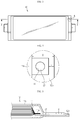
- FIG. 2 is a plane view showing a battery module according to an embodiment of the present disclosure.
- a battery module includes a pouch-type battery cell 10, a voltage sensor 20 for sensing a voltage of the battery cell 10, and a sensing wire 30 for electrically connecting a positive electrode and a negative electrode of the battery cell 10 to the voltage sensor 20.
- the battery cell 10 employed at the present disclosure is a pouch-type battery cell and includes an electrode assembly 11, a pouch case 12, a pair of electrode leads 13, 15, a pair of sealants 14, 16 and a sensing lead 17.
- the electrode assembly 11 is configured so that a positive electrode plate, a separator and a negative electrode plate are stacked at least once, and the separator is preferably located at both outer sides for insulation.
- the positive electrode plate includes a positive electrode current collector and a positive electrode active material layer coated on at least one surface thereof, and a positive electrode uncoated region not coated with the positive electrode active material layer is formed at one end thereof.
- the positive electrode uncoated region serves as a positive electrode tab 11a connected to the positive electrode lead 13.
- the negative electrode plate includes a negative electrode current collector and a negative electrode active material layer coated on at least one surface thereof, and an uncoated region not coated with the active material layer is formed at one end thereof.
- the uncoated region serves as a negative electrode tab 11a connected to the negative electrode lead 15.
- the electrode lead 13 located at the right in FIG. 2 is called a positive electrode lead, and the electrode lead 15 located at the left is called a negative electrode lead.
- the present disclosure is not limited thereto, and the polarities may be formed on the contrary.
- the positive electrode plate and the negative electrode plate are disposed so that the electrode tabs 11a having different polarities, namely the positive electrode tab and the negative electrode tab, are oriented to opposite sides.
- the separator is interposed between the positive electrode plate and the negative electrode plate to prevent the electrode plates having different polarities from directly contacting, and is made of a porous material to allow ion passage.
- the electrode leads 13, 15 are classified into a positive electrode lead 13 connected to the positive electrode tab and a negative electrode lead 15 connected to the negative electrode tab. Since the positive electrode tab and the negative electrode tab are oriented oppositely as described above, the positive electrode lead 13 and the negative electrode lead 15 also extend in opposite directions accordingly.
- the electrode leads 13, 15 are generally made of an aluminum material coated with nickel, and such metallic electrode leads 13, 15 are not easily adhered to an inner surface of the pouch case 12 when the pouch case 12 is sealed.
- sealants 14, 16 made of a resin material with good adhesion to the inner surface of the pouch case 12 may be attached to the periphery of the electrode leads 13, 15.
- the pouch case 12 may be composed of an upper case and a lower case, and the upper case and the lower case may be respectively made of a multilayered porous film composed of a first resin layer, a metal layer and a second resin layer.
- the first resin layer forming an innermost surface of the pouch film may be made of a resin with a thermal bonding property so that the upper case and the lower case may be easily fused to each other when heat is applied thereto in a state where the upper case and the lower case are in contact.
- the pouch case 12 may be classified into two portions, namely an accommodation portion 12a for accommodating the electrode assembly 11 and a sealing portion 12b extending in a circumferential direction of the accommodation portion 12a so that the electrode leads 13, 15 drawn to the outside is thermally fused thereto to seal the pouch case 12.
- a region where the electrode leads 13, 15 pass may have weak sealing, and thus the sealants 14, 16 are applied to the corresponding region.
- the sealants 14, 16 are interposed between the inner surfaces of the upper pouch case and the lower pouch case in a state of being attached to the peripheries of the electrode leads 13, 15.
- the battery cell 10 employed at the present disclosure further includes a sensing lead 17 for voltage sensing, in addition to the pair of electrode leads 13, 15.
- the sensing lead 17 may have positive polarity or negative polarity.
- the sensing lead 17 is located to be adjacent to any one of the positive electrode lead 13 and the negative electrode lead 15.
- the sensing lead 17 is located on the sealing portion 12b provided in a side where the positive electrode lead 13 is drawn as shown in FIG. 2 , the sensing lead 17 has negative polarity, and if the sensing lead 17 is located in a side where the negative electrode lead 15 contrary to FIG. 2 , the sensing lead 17 has positive polarity.
- sensing lead 17 will be described in more detail with reference to FIGS. 3 to 5 .
- FIG. 3 is a plane view showing a battery cell employed at the present disclosure
- FIG. 4 is an enlarged view showing a portion A of FIG. 3
- FIG. 5 is a diagram showing an example of the battery cell employed at the present disclosure and is a cross-sectioned view, taken along the line X-X' of FIG. 3 .
- the sensing lead 17 is a component located at the sealing portion 12b at one side or the other side of the battery cell 10.
- the sensing lead 17 is bonded to the electrode tab 11a of the electrode assembly 11 and extends in parallel to the positive electrode lead 13 or the negative electrode lead 15 adjacent thereto.
- the sensing lead 17 does not extend to the outside of the pouch case 12 but is located at the inside thereof, and is exposed to the outside through a sensing hole H formed in a part of the sealing portion 12b of the pouch case 12.
- a region where the sensing lead 17 is located is not sealed.
- a sealing width D of the region where the sensing lead 17 is located is smaller.
- the sealing width D of the region where the sensing lead 17 is located is preferably 1/4 or above of the entire width of the sealing portion 12b.
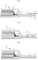
- FIG. 6 is a diagram showing that a sensing wire is connected to the battery cell depicted in FIG. 5 .
- FIG. 7 is a diagram showing an embodiment in which a gasket is applied to the battery cell depicted in FIG. 5 .
- the sensing wire 30 may be bonded to the sensing lead 17 by using a solder S.
- the present disclosure depict only a case where the sensing hole H is formed in the upper surface of the pouch case 12, the present disclosure is not limited thereto, and the sensing hole H may be formed in the lower surface thereof, instead of the upper surface, if necessary.
- the battery cell 10 employed at the present disclosure may further include a gasket 18 for preventing the sealing property of the pouch case 12 from deteriorating due to the sensing hole H.
- the gasket 18 is inserted into an edge of the sensing hole H and is interposed between the sensing lead 17 and the inner surface of the pouch case 12 to seal a region where the sensing hole H is formed.
- the gasket 18 covers the inner wall of the sensing hole H to prevent the metal layer from being exposed to the outside through the inner wall of the sensing hole H, namely a cut surface for forming the sensing hole H, thereby preventing the occurrence of short circuit by the metal layer.
- FIG. 8 is a diagram showing another example of the battery cell employed at the present disclosure and is a cross-sectioned view, taken along the line X-X' of FIG. 3
- FIG. 9 is a diagram showing that a sensing wire is connected to the battery cell depicted in FIG. 8
- FIG. 10 is a diagram showing an embodiment in which a gasket is applied to the battery cell depicted in FIG. 8 .
- the battery cell 10 employed at the present disclosure may have the sensing hole H in both of the upper and lower surfaces of the pouch case 12, different from FIG. 5 .
- the sensing wire 20 and the sensing lead 17 may be electrically connected by using a receptacle 31.
- the receptacle 31 is connected to one end of the sensing wire 30, and a pair of contact portions 31a formed at the end elastically press both surfaces of the sensing lead 17 so that the battery cell 10 and the voltage sensor 20 may be electrically connected in a stable and convenient way.
- the contact portion 31a may be shaped and sized to correspond to the sensing hole H.
- the sensing holes H formed in both surfaces of the pouch case 12 may be sealed by the gasket 18, similar to the embodiment depicted in FIG. 7 .
- the battery module according to an embodiment of the present disclosure includes the sensing lead 17 exposed to the outside through the sealing portion 12b, it is not needed to respectively connect the sensing wire 30 to the electrode leads 13, 15 drawn in opposite directions.
- the battery module according to an embodiment of the present disclosure is configured such that the battery cell 10 and the voltage sensor 20 are electrically connected through the sensing lead 17 and one electrode lead located adjacent to one side of the battery cell 17, and thus has a structural advantage in that the extending length of the sensing wire 30 may be shortened.
Landscapes
- Chemical & Material Sciences (AREA)
- Chemical Kinetics & Catalysis (AREA)
- Electrochemistry (AREA)
- General Chemical & Material Sciences (AREA)
- Engineering & Computer Science (AREA)
- Manufacturing & Machinery (AREA)
- Inorganic Chemistry (AREA)
- Connection Of Batteries Or Terminals (AREA)
- Battery Mounting, Suspending (AREA)
- Sealing Battery Cases Or Jackets (AREA)
- Secondary Cells (AREA)
Applications Claiming Priority (2)
| Application Number | Priority Date | Filing Date | Title |
|---|---|---|---|
| KR1020170035400A KR102137756B1 (ko) | 2017-03-21 | 2017-03-21 | 간단한 센싱 구조를 구비하는 배터리 모듈 |
| PCT/KR2018/002145 WO2018174417A1 (ko) | 2017-03-21 | 2018-02-21 | 간단한 센싱 구조를 구비하는 배터리 모듈 |
Publications (3)
| Publication Number | Publication Date |
|---|---|
| EP3483980A1 true EP3483980A1 (de) | 2019-05-15 |
| EP3483980A4 EP3483980A4 (de) | 2019-08-07 |
| EP3483980B1 EP3483980B1 (de) | 2025-06-04 |
Family
ID=63584635
Family Applications (1)
| Application Number | Title | Priority Date | Filing Date |
|---|---|---|---|
| EP18772425.7A Active EP3483980B1 (de) | 2017-03-21 | 2018-02-21 | Batteriemodul mit einfacher sensorstruktur |
Country Status (8)
| Country | Link |
|---|---|
| US (2) | US20190237824A1 (de) |
| EP (1) | EP3483980B1 (de) |
| JP (1) | JP6785949B2 (de) |
| KR (1) | KR102137756B1 (de) |
| CN (1) | CN109964362B (de) |
| ES (1) | ES3034303T3 (de) |
| HU (1) | HUE071707T2 (de) |
| WO (1) | WO2018174417A1 (de) |
Families Citing this family (5)
| Publication number | Priority date | Publication date | Assignee | Title |
|---|---|---|---|---|
| JP7484636B2 (ja) * | 2020-09-30 | 2024-05-16 | トヨタ自動車株式会社 | 電池 |
| KR102861228B1 (ko) * | 2020-11-03 | 2025-09-18 | 주식회사 엘지에너지솔루션 | 주행 방향을 따라 가스 포켓부가 형성되는 전지케이스, 이를 이용하여 제조된 전지셀, 및 상기 전지셀 제조방법 |
| KR102868277B1 (ko) * | 2021-11-18 | 2025-10-10 | 주식회사 엘지에너지솔루션 | 센싱부재를 포함하는 파우치형 전지셀 및 이를 포함하는 전지모듈 |
| DE102022103728B3 (de) * | 2022-02-17 | 2023-03-09 | Dr. Ing. H.C. F. Porsche Aktiengesellschaft | Batteriezelle |
| WO2025211905A1 (ko) * | 2024-04-02 | 2025-10-09 | 주식회사 엘지에너지솔루션 | 위치 정렬이 용이한 파우치 전지셀 실링장치 및 이를 이용한 파우치 전지셀 실링방법 |
Family Cites Families (24)
| Publication number | Priority date | Publication date | Assignee | Title |
|---|---|---|---|---|
| JPH1131486A (ja) * | 1997-07-08 | 1999-02-02 | Ricoh Co Ltd | 扁平型電池 |
| US5948562A (en) * | 1997-11-03 | 1999-09-07 | Motorola, Inc. | Energy storage device |
| JP3503516B2 (ja) * | 1999-02-25 | 2004-03-08 | 三菱電機株式会社 | 薄型電池、電子機器及び薄型電池の製造方法 |
| AUPR199400A0 (en) * | 2000-12-09 | 2001-01-11 | Energy Storage Systems Pty Ltd | A connection between a conductive substrate and a laminate |
| JP3896911B2 (ja) * | 2002-06-28 | 2007-03-22 | 日産自動車株式会社 | 両タブ型セルおよび組電池 |
| JP4107054B2 (ja) * | 2002-11-08 | 2008-06-25 | 日産自動車株式会社 | 薄型電池 |
| JP4661648B2 (ja) * | 2005-06-16 | 2011-03-30 | 日産自動車株式会社 | 扁平型電池および該扁平型電池を用いた組電池 |
| CN100444430C (zh) * | 2005-06-16 | 2008-12-17 | 日产自动车株式会社 | 扁平型电池及采用该扁平型电池的电池组 |
| JP5219587B2 (ja) * | 2008-03-31 | 2013-06-26 | 三洋電機株式会社 | ラミネート式電池及びそのラミネート式電池を備えた電池モジュール |
| KR101071538B1 (ko) * | 2009-05-04 | 2011-10-10 | 주식회사 엘지화학 | 전압 센싱부재 및 이를 포함하는 전지모듈 |
| JP5443097B2 (ja) * | 2009-08-18 | 2014-03-19 | 矢崎総業株式会社 | 電源装置 |
| KR101217564B1 (ko) * | 2010-08-16 | 2013-01-02 | 주식회사 엘지화학 | 전압 검출 어셈블리 및 이를 포함하는 전지모듈 |
| US8895177B2 (en) * | 2010-11-18 | 2014-11-25 | Robert Bosch Gmbh | Modular battery pack systems for prismatic cells |
| JP2014525658A (ja) * | 2011-08-31 | 2014-09-29 | エルジー・ケム・リミテッド | 水分浸透に対する長期信頼性が向上した二次電池 |
| KR101369308B1 (ko) * | 2012-04-06 | 2014-03-07 | 인지컨트롤스 주식회사 | 전기자동차용 배터리 |
| KR20140013132A (ko) * | 2012-07-09 | 2014-02-05 | 에스케이이노베이션 주식회사 | 이차전지 |
| KR101984314B1 (ko) * | 2012-12-26 | 2019-05-30 | 에스케이이노베이션 주식회사 | 이차전지 |
| KR101577387B1 (ko) * | 2013-05-06 | 2015-12-16 | 주식회사 엘지화학 | 이차전지, 이를 포함하는 이차전지 모듈 및 이차전지 팩 |
| KR101743696B1 (ko) * | 2013-11-29 | 2017-06-05 | 주식회사 엘지화학 | 배터리 모듈 및 이를 포함하는 배터리 팩 |
| JP6097678B2 (ja) * | 2013-12-18 | 2017-03-15 | 株式会社富士通テレコムネットワークス福島 | 接触不良を検出する充放電試験装置 |
| JP2015125878A (ja) * | 2013-12-26 | 2015-07-06 | 株式会社デンソー | 電池セル及び組電池 |
| KR20160054268A (ko) * | 2014-11-06 | 2016-05-16 | 주식회사 엘지화학 | 이차전지셀 및 이를 포함하는 배터리 모듈 |
| JP6202024B2 (ja) * | 2015-03-10 | 2017-09-27 | トヨタ自動車株式会社 | 電池モジュール |
| KR101953362B1 (ko) * | 2015-09-02 | 2019-05-22 | 주식회사 엘지화학 | 개선된 체결구조를 갖는 배터리 모듈 |
-
2017
- 2017-03-21 KR KR1020170035400A patent/KR102137756B1/ko active Active
-
2018
- 2018-02-21 CN CN201880003040.8A patent/CN109964362B/zh active Active
- 2018-02-21 WO PCT/KR2018/002145 patent/WO2018174417A1/ko not_active Ceased
- 2018-02-21 JP JP2019509536A patent/JP6785949B2/ja active Active
- 2018-02-21 US US16/313,637 patent/US20190237824A1/en not_active Abandoned
- 2018-02-21 ES ES18772425T patent/ES3034303T3/es active Active
- 2018-02-21 HU HUE18772425A patent/HUE071707T2/hu unknown
- 2018-02-21 EP EP18772425.7A patent/EP3483980B1/de active Active
-
2023
- 2023-02-28 US US18/115,669 patent/US20230207911A1/en active Pending
Also Published As
| Publication number | Publication date |
|---|---|
| WO2018174417A1 (ko) | 2018-09-27 |
| JP6785949B2 (ja) | 2020-11-18 |
| KR102137756B1 (ko) | 2020-07-24 |
| US20190237824A1 (en) | 2019-08-01 |
| ES3034303T3 (en) | 2025-08-14 |
| EP3483980B1 (de) | 2025-06-04 |
| US20230207911A1 (en) | 2023-06-29 |
| KR20180106689A (ko) | 2018-10-01 |
| CN109964362A (zh) | 2019-07-02 |
| JP2019525432A (ja) | 2019-09-05 |
| HUE071707T2 (hu) | 2025-09-28 |
| CN109964362B (zh) | 2024-02-06 |
| EP3483980A4 (de) | 2019-08-07 |
Similar Documents
| Publication | Publication Date | Title |
|---|---|---|
| US20230207911A1 (en) | Battery module having simple sensing structure | |
| US6387566B1 (en) | Battery with laminated insulator/metal/insulator case | |
| EP3174126B1 (de) | Wiederaufladbare batterie | |
| US11133545B2 (en) | Prismatic secondary battery and method for manufacturing same | |
| US9028993B2 (en) | Secondary battery | |
| US9287534B2 (en) | Rechargeable battery | |
| US9799874B2 (en) | Rechargeable battery | |
| US20110104562A1 (en) | Secondary battery | |
| JP5040698B2 (ja) | キャパシタ | |
| US9553340B2 (en) | Rechargeable battery module | |
| WO2016017048A1 (ja) | 電池パック | |
| KR102256603B1 (ko) | 높은 에너지 밀도를 갖는 배터리 셀 | |
| KR20170009298A (ko) | 이차전지 | |
| KR102510891B1 (ko) | 이차전지 | |
| US20240106019A1 (en) | Secondary battery | |
| CN104167525A (zh) | 可再充电电池 | |
| EP2736099A1 (de) | Wiederaufladbare Batterie | |
| US20240014514A1 (en) | Secondary battery | |
| EP4164051A1 (de) | Sekundärbatterie | |
| KR101769106B1 (ko) | 파우치형 이차전지 및 이에 적용되는 전극 리드 어셈블리 | |
| US10320035B2 (en) | Battery pack | |
| US9520579B2 (en) | Rechargeable battery | |
| CN223797424U (zh) | 二次电池 | |
| KR102876010B1 (ko) | 이차전지 | |
| KR20200114783A (ko) | 이차전지, 전지 팩 및 전지 모듈 |
Legal Events
| Date | Code | Title | Description |
|---|---|---|---|
| STAA | Information on the status of an ep patent application or granted ep patent |
Free format text: STATUS: THE INTERNATIONAL PUBLICATION HAS BEEN MADE |
|
| PUAI | Public reference made under article 153(3) epc to a published international application that has entered the european phase |
Free format text: ORIGINAL CODE: 0009012 |
|
| STAA | Information on the status of an ep patent application or granted ep patent |
Free format text: STATUS: REQUEST FOR EXAMINATION WAS MADE |
|
| 17P | Request for examination filed |
Effective date: 20190206 |
|
| AK | Designated contracting states |
Kind code of ref document: A1 Designated state(s): AL AT BE BG CH CY CZ DE DK EE ES FI FR GB GR HR HU IE IS IT LI LT LU LV MC MK MT NL NO PL PT RO RS SE SI SK SM TR |
|
| AX | Request for extension of the european patent |
Extension state: BA ME |
|
| A4 | Supplementary search report drawn up and despatched |
Effective date: 20190710 |
|
| RIC1 | Information provided on ipc code assigned before grant |
Ipc: H01M 10/48 20060101AFI20190704BHEP Ipc: H01M 2/26 20060101ALI20190704BHEP Ipc: H01M 2/02 20060101ALI20190704BHEP |
|
| DAV | Request for validation of the european patent (deleted) | ||
| DAX | Request for extension of the european patent (deleted) | ||
| STAA | Information on the status of an ep patent application or granted ep patent |
Free format text: STATUS: EXAMINATION IS IN PROGRESS |
|
| 17Q | First examination report despatched |
Effective date: 20210422 |
|
| RAP1 | Party data changed (applicant data changed or rights of an application transferred) |
Owner name: LG ENERGY SOLUTION LTD. |
|
| RAP3 | Party data changed (applicant data changed or rights of an application transferred) |
Owner name: LG ENERGY SOLUTION, LTD. |
|
| REG | Reference to a national code |
Ref country code: DE Ipc: H01M0050553000 Ref country code: DE Ref legal event code: R079 Ref document number: 602018082410 Country of ref document: DE Free format text: PREVIOUS MAIN CLASS: H01M0010480000 Ipc: H01M0050553000 |
|
| RIC1 | Information provided on ipc code assigned before grant |
Ipc: H01M 50/534 20210101ALN20250109BHEP Ipc: H01M 50/129 20210101ALN20250109BHEP Ipc: H01M 50/121 20210101ALN20250109BHEP Ipc: H01M 50/119 20210101ALN20250109BHEP Ipc: H01M 50/548 20210101ALI20250109BHEP Ipc: H01M 50/105 20210101ALI20250109BHEP Ipc: H01M 10/48 20060101ALI20250109BHEP Ipc: H01M 50/553 20210101AFI20250109BHEP |
|
| GRAP | Despatch of communication of intention to grant a patent |
Free format text: ORIGINAL CODE: EPIDOSNIGR1 |
|
| STAA | Information on the status of an ep patent application or granted ep patent |
Free format text: STATUS: GRANT OF PATENT IS INTENDED |
|
| INTG | Intention to grant announced |
Effective date: 20250218 |
|
| GRAS | Grant fee paid |
Free format text: ORIGINAL CODE: EPIDOSNIGR3 |
|
| P01 | Opt-out of the competence of the unified patent court (upc) registered |
Free format text: CASE NUMBER: APP_14836/2025 Effective date: 20250326 |
|
| GRAA | (expected) grant |
Free format text: ORIGINAL CODE: 0009210 |
|
| STAA | Information on the status of an ep patent application or granted ep patent |
Free format text: STATUS: THE PATENT HAS BEEN GRANTED |
|
| AK | Designated contracting states |
Kind code of ref document: B1 Designated state(s): AL AT BE BG CH CY CZ DE DK EE ES FI FR GB GR HR HU IE IS IT LI LT LU LV MC MK MT NL NO PL PT RO RS SE SI SK SM TR |
|
| REG | Reference to a national code |
Ref country code: GB Ref legal event code: FG4D |
|
| REG | Reference to a national code |
Ref country code: CH Ref legal event code: EP |
|
| REG | Reference to a national code |
Ref country code: DE Ref legal event code: R096 Ref document number: 602018082410 Country of ref document: DE |
|
| REG | Reference to a national code |
Ref country code: IE Ref legal event code: FG4D |
|
| REG | Reference to a national code |
Ref country code: ES Ref legal event code: FG2A Ref document number: 3034303 Country of ref document: ES Kind code of ref document: T3 Effective date: 20250814 |
|
| REG | Reference to a national code |
Ref country code: HU Ref legal event code: AG4A Ref document number: E071707 Country of ref document: HU |
|
| REG | Reference to a national code |
Ref country code: NL Ref legal event code: MP Effective date: 20250604 |
|
| PG25 | Lapsed in a contracting state [announced via postgrant information from national office to epo] |
Ref country code: FI Free format text: LAPSE BECAUSE OF FAILURE TO SUBMIT A TRANSLATION OF THE DESCRIPTION OR TO PAY THE FEE WITHIN THE PRESCRIBED TIME-LIMIT Effective date: 20250604 |
|
| REG | Reference to a national code |
Ref country code: LT Ref legal event code: MG9D |
|
| PG25 | Lapsed in a contracting state [announced via postgrant information from national office to epo] |
Ref country code: NO Free format text: LAPSE BECAUSE OF FAILURE TO SUBMIT A TRANSLATION OF THE DESCRIPTION OR TO PAY THE FEE WITHIN THE PRESCRIBED TIME-LIMIT Effective date: 20250904 Ref country code: GR Free format text: LAPSE BECAUSE OF FAILURE TO SUBMIT A TRANSLATION OF THE DESCRIPTION OR TO PAY THE FEE WITHIN THE PRESCRIBED TIME-LIMIT Effective date: 20250905 |
|
| PG25 | Lapsed in a contracting state [announced via postgrant information from national office to epo] |
Ref country code: PL Free format text: LAPSE BECAUSE OF FAILURE TO SUBMIT A TRANSLATION OF THE DESCRIPTION OR TO PAY THE FEE WITHIN THE PRESCRIBED TIME-LIMIT Effective date: 20250604 |
|
| PG25 | Lapsed in a contracting state [announced via postgrant information from national office to epo] |
Ref country code: BG Free format text: LAPSE BECAUSE OF FAILURE TO SUBMIT A TRANSLATION OF THE DESCRIPTION OR TO PAY THE FEE WITHIN THE PRESCRIBED TIME-LIMIT Effective date: 20250604 |
|
| PG25 | Lapsed in a contracting state [announced via postgrant information from national office to epo] |
Ref country code: HR Free format text: LAPSE BECAUSE OF FAILURE TO SUBMIT A TRANSLATION OF THE DESCRIPTION OR TO PAY THE FEE WITHIN THE PRESCRIBED TIME-LIMIT Effective date: 20250604 |
|
| PG25 | Lapsed in a contracting state [announced via postgrant information from national office to epo] |
Ref country code: RS Free format text: LAPSE BECAUSE OF FAILURE TO SUBMIT A TRANSLATION OF THE DESCRIPTION OR TO PAY THE FEE WITHIN THE PRESCRIBED TIME-LIMIT Effective date: 20250904 |
|
| PG25 | Lapsed in a contracting state [announced via postgrant information from national office to epo] |
Ref country code: LV Free format text: LAPSE BECAUSE OF FAILURE TO SUBMIT A TRANSLATION OF THE DESCRIPTION OR TO PAY THE FEE WITHIN THE PRESCRIBED TIME-LIMIT Effective date: 20250604 |
|
| PG25 | Lapsed in a contracting state [announced via postgrant information from national office to epo] |
Ref country code: NL Free format text: LAPSE BECAUSE OF FAILURE TO SUBMIT A TRANSLATION OF THE DESCRIPTION OR TO PAY THE FEE WITHIN THE PRESCRIBED TIME-LIMIT Effective date: 20250604 |
|
| PG25 | Lapsed in a contracting state [announced via postgrant information from national office to epo] |
Ref country code: PT Free format text: LAPSE BECAUSE OF FAILURE TO SUBMIT A TRANSLATION OF THE DESCRIPTION OR TO PAY THE FEE WITHIN THE PRESCRIBED TIME-LIMIT Effective date: 20251006 |
|
| REG | Reference to a national code |
Ref country code: AT Ref legal event code: MK05 Ref document number: 1801298 Country of ref document: AT Kind code of ref document: T Effective date: 20250604 |
|
| PG25 | Lapsed in a contracting state [announced via postgrant information from national office to epo] |
Ref country code: IS Free format text: LAPSE BECAUSE OF FAILURE TO SUBMIT A TRANSLATION OF THE DESCRIPTION OR TO PAY THE FEE WITHIN THE PRESCRIBED TIME-LIMIT Effective date: 20251004 |
|
| PG25 | Lapsed in a contracting state [announced via postgrant information from national office to epo] |
Ref country code: SM Free format text: LAPSE BECAUSE OF FAILURE TO SUBMIT A TRANSLATION OF THE DESCRIPTION OR TO PAY THE FEE WITHIN THE PRESCRIBED TIME-LIMIT Effective date: 20250604 Ref country code: AT Free format text: LAPSE BECAUSE OF FAILURE TO SUBMIT A TRANSLATION OF THE DESCRIPTION OR TO PAY THE FEE WITHIN THE PRESCRIBED TIME-LIMIT Effective date: 20250604 |
|
| PG25 | Lapsed in a contracting state [announced via postgrant information from national office to epo] |
Ref country code: CZ Free format text: LAPSE BECAUSE OF FAILURE TO SUBMIT A TRANSLATION OF THE DESCRIPTION OR TO PAY THE FEE WITHIN THE PRESCRIBED TIME-LIMIT Effective date: 20250604 |
|
| PG25 | Lapsed in a contracting state [announced via postgrant information from national office to epo] |
Ref country code: EE Free format text: LAPSE BECAUSE OF FAILURE TO SUBMIT A TRANSLATION OF THE DESCRIPTION OR TO PAY THE FEE WITHIN THE PRESCRIBED TIME-LIMIT Effective date: 20250604 |
|
| PG25 | Lapsed in a contracting state [announced via postgrant information from national office to epo] |
Ref country code: SK Free format text: LAPSE BECAUSE OF FAILURE TO SUBMIT A TRANSLATION OF THE DESCRIPTION OR TO PAY THE FEE WITHIN THE PRESCRIBED TIME-LIMIT Effective date: 20250604 Ref country code: RO Free format text: LAPSE BECAUSE OF FAILURE TO SUBMIT A TRANSLATION OF THE DESCRIPTION OR TO PAY THE FEE WITHIN THE PRESCRIBED TIME-LIMIT Effective date: 20250604 |
|
| PG25 | Lapsed in a contracting state [announced via postgrant information from national office to epo] |
Ref country code: IT Free format text: LAPSE BECAUSE OF FAILURE TO SUBMIT A TRANSLATION OF THE DESCRIPTION OR TO PAY THE FEE WITHIN THE PRESCRIBED TIME-LIMIT Effective date: 20250604 |