US9028993B2 - Secondary battery - Google Patents
Secondary battery Download PDFInfo
- Publication number
- US9028993B2 US9028993B2 US12/805,743 US80574310A US9028993B2 US 9028993 B2 US9028993 B2 US 9028993B2 US 80574310 A US80574310 A US 80574310A US 9028993 B2 US9028993 B2 US 9028993B2
- Authority
- US
- United States
- Prior art keywords
- current collector
- secondary battery
- electrode assembly
- inducing member
- short
- Prior art date
- Legal status (The legal status is an assumption and is not a legal conclusion. Google has not performed a legal analysis and makes no representation as to the accuracy of the status listed.)
- Active, expires
Links
Images


Classifications
-
- H01M2/1252—
-
- H—ELECTRICITY
- H01—ELECTRIC ELEMENTS
- H01M—PROCESSES OR MEANS, e.g. BATTERIES, FOR THE DIRECT CONVERSION OF CHEMICAL ENERGY INTO ELECTRICAL ENERGY
- H01M10/00—Secondary cells; Manufacture thereof
- H01M10/04—Construction or manufacture in general
- H01M10/0431—Cells with wound or folded electrodes
-
- H—ELECTRICITY
- H01—ELECTRIC ELEMENTS
- H01M—PROCESSES OR MEANS, e.g. BATTERIES, FOR THE DIRECT CONVERSION OF CHEMICAL ENERGY INTO ELECTRICAL ENERGY
- H01M50/00—Constructional details or processes of manufacture of the non-active parts of electrochemical cells other than fuel cells, e.g. hybrid cells
- H01M50/50—Current conducting connections for cells or batteries
- H01M50/572—Means for preventing undesired use or discharge
- H01M50/574—Devices or arrangements for the interruption of current
- H01M50/579—Devices or arrangements for the interruption of current in response to shock
-
- H01M2/1241—
-
- H01M2/263—
-
- H01M2/347—
-
- H—ELECTRICITY
- H01—ELECTRIC ELEMENTS
- H01M—PROCESSES OR MEANS, e.g. BATTERIES, FOR THE DIRECT CONVERSION OF CHEMICAL ENERGY INTO ELECTRICAL ENERGY
- H01M50/00—Constructional details or processes of manufacture of the non-active parts of electrochemical cells other than fuel cells, e.g. hybrid cells
- H01M50/10—Primary casings; Jackets or wrappings
- H01M50/102—Primary casings; Jackets or wrappings characterised by their shape or physical structure
- H01M50/103—Primary casings; Jackets or wrappings characterised by their shape or physical structure prismatic or rectangular
-
- H—ELECTRICITY
- H01—ELECTRIC ELEMENTS
- H01M—PROCESSES OR MEANS, e.g. BATTERIES, FOR THE DIRECT CONVERSION OF CHEMICAL ENERGY INTO ELECTRICAL ENERGY
- H01M50/00—Constructional details or processes of manufacture of the non-active parts of electrochemical cells other than fuel cells, e.g. hybrid cells
- H01M50/30—Arrangements for facilitating escape of gases
- H01M50/342—Non-re-sealable arrangements
- H01M50/3425—Non-re-sealable arrangements in the form of rupturable membranes or weakened parts, e.g. pierced with the aid of a sharp member
-
- H—ELECTRICITY
- H01—ELECTRIC ELEMENTS
- H01M—PROCESSES OR MEANS, e.g. BATTERIES, FOR THE DIRECT CONVERSION OF CHEMICAL ENERGY INTO ELECTRICAL ENERGY
- H01M50/00—Constructional details or processes of manufacture of the non-active parts of electrochemical cells other than fuel cells, e.g. hybrid cells
- H01M50/30—Arrangements for facilitating escape of gases
- H01M50/35—Gas exhaust passages comprising elongated, tortuous or labyrinth-shaped exhaust passages
- H01M50/367—Internal gas exhaust passages forming part of the battery cover or case; Double cover vent systems
-
- H—ELECTRICITY
- H01—ELECTRIC ELEMENTS
- H01M—PROCESSES OR MEANS, e.g. BATTERIES, FOR THE DIRECT CONVERSION OF CHEMICAL ENERGY INTO ELECTRICAL ENERGY
- H01M50/00—Constructional details or processes of manufacture of the non-active parts of electrochemical cells other than fuel cells, e.g. hybrid cells
- H01M50/50—Current conducting connections for cells or batteries
- H01M50/531—Electrode connections inside a battery casing
- H01M50/538—Connection of several leads or tabs of wound or folded electrode stacks
-
- H—ELECTRICITY
- H01—ELECTRIC ELEMENTS
- H01M—PROCESSES OR MEANS, e.g. BATTERIES, FOR THE DIRECT CONVERSION OF CHEMICAL ENERGY INTO ELECTRICAL ENERGY
- H01M2200/00—Safety devices for primary or secondary batteries
-
- Y—GENERAL TAGGING OF NEW TECHNOLOGICAL DEVELOPMENTS; GENERAL TAGGING OF CROSS-SECTIONAL TECHNOLOGIES SPANNING OVER SEVERAL SECTIONS OF THE IPC; TECHNICAL SUBJECTS COVERED BY FORMER USPC CROSS-REFERENCE ART COLLECTIONS [XRACs] AND DIGESTS
- Y02—TECHNOLOGIES OR APPLICATIONS FOR MITIGATION OR ADAPTATION AGAINST CLIMATE CHANGE
- Y02E—REDUCTION OF GREENHOUSE GAS [GHG] EMISSIONS, RELATED TO ENERGY GENERATION, TRANSMISSION OR DISTRIBUTION
- Y02E60/00—Enabling technologies; Technologies with a potential or indirect contribution to GHG emissions mitigation
- Y02E60/10—Energy storage using batteries
-
- Y—GENERAL TAGGING OF NEW TECHNOLOGICAL DEVELOPMENTS; GENERAL TAGGING OF CROSS-SECTIONAL TECHNOLOGIES SPANNING OVER SEVERAL SECTIONS OF THE IPC; TECHNICAL SUBJECTS COVERED BY FORMER USPC CROSS-REFERENCE ART COLLECTIONS [XRACs] AND DIGESTS
- Y02—TECHNOLOGIES OR APPLICATIONS FOR MITIGATION OR ADAPTATION AGAINST CLIMATE CHANGE
- Y02P—CLIMATE CHANGE MITIGATION TECHNOLOGIES IN THE PRODUCTION OR PROCESSING OF GOODS
- Y02P70/00—Climate change mitigation technologies in the production process for final industrial or consumer products
- Y02P70/50—Manufacturing or production processes characterised by the final manufactured product
Definitions
- Embodiments relate to a secondary battery.
- Secondary batteries are batteries that can be repeated charged and discharged, unlike primary batteries that cannot be recharged. Secondary batteries are widely used in high-technology electronic devices, e.g., cellular phones, laptops, and camcorders, and may also be used for vehicles.
- Secondary batteries may include an electrode assembly and an electrolyte.
- the electrode assembly may include a positive plate, a negative plate, and a separator.
- the electrolyte may mostly include a lithium ion.
- the positive plate and the negative plate of the electrode assembly may each include an electrode tab protruding from the electrode assembly.
- the electrode assembly may be accommodated inside a case, and an electrode terminal may be exposed outside the case.
- the electrode tab that protrudes outside of the electrode assembly may be electrically connected to the electrode terminal.
- the case may have, e.g., a cylindrical shape or an angular shape.
- Secondary batteries may be used in harsh environments, e.g., an environment that may expose the secondary battery to crushing or a shock. Accordingly, secondary batteries should exhibit excellent stability and reliability even in such harsh environments.
- Embodiments are directed to a secondary battery, which represents advances over the related art.
- a secondary battery including an electrode assembly, the electrode assembly including a first electrode plate, a separator, and a second electrode plate; a case, the case accommodating the electrode assembly; a first current collector and a second current collector electrically connected to the first electrode plate and the second electrode plate of the electrode assembly, respectively; and a short inducing member disposed between the first current collector and the second current collector, the short inducing member being configured to electrically short-circuit the first current collector and the second current collector when a shape of the case is changed.
- the first electrode plate, the separator, and the second electrode plate may be wound in a jelly roll configuration.
- the first current collector may contact the first electrode plate at an end of the electrode assembly, and the second current collector may contact the second electrode plate at another end of the electrode assembly.
- the short inducing member may extend in a lengthwise direction of a circumferential surface of the jelly roll configuration of the electrode assembly.
- the secondary battery may further include an insulating member disposed between the short inducing member and the electrode assembly.
- the short inducing member may be coupled to the electrode assembly with insulating tape.
- the short inducing member may be electrically isolated from the first current collector and the second current collector.
- the short inducing member may be electrically connected to one of the first current collector and the second current connector and may be electrically isolated from the other of the first current collector and the second current connector.
- the short inducing member may be integrated in one unit with the one of the first current collector and the second current connector that is electrically connected to the short inducing member.
- the short inducing member may be attached to the one of the first current collector and the second current connector that is electrically connected to the short inducing member.
- a part of at least one of the first current collector and the second current collector may be bent over the circumferential surface of the electrode assembly.
- One side of the case may include an opening, and the secondary battery may include a cap plate for sealing the opening of the case.
- the secondary battery may further include a degassing duct disposed between the cap plate and the short inducing member, the degassing duct forming a gas passage.
- the short inducing member may be attached to a surface of the degassing duct, which faces the electrode assembly.
- the degassing duct may support the electrode assembly with respect to the cap plate.
- the degassing duct may be formed of an insulating material.
- the short inducing member may include copper.
- a degree of change in the shape of the case may correspond to a distance between the short inducing member and at least one of the first current collector and the second current collector.
- the short inducing member may be configured to induce a short in the secondary battery when the shape of the case is changed in any of an X-X′, Y-Y′, and Z-Z′ direction.
- the case may be configured to change shape when an external pressure applied thereto exceeds a predetermined level, when the external pressure does not exceed the predetermined level, the short inducing member may be electrically isolated from at least one of the first current collector and the second current collector, and when the external pressure exceeds the predetermined level, the short inducing member may electrically short-circuit the first current collector and the second current collector.
- FIG. 1 illustrates a perspective view of a secondary battery according to an embodiment
- FIG. 2 illustrates a cross-sectional view taken along a line II-II of FIG. 1 ;
- FIG. 3 illustrates a partial exploded perspective view of the secondary battery of FIG. 1 , wherein a view of a short inducing member is shown in exploded view;
- FIG. 4 illustrates a sectional view of a secondary battery according to another embodiment
- FIG. 5 illustrates a partial exploded perspective view of the secondary battery of FIG. 4 , wherein a view of a short inducing member is shown in exploded view;
- FIG. 6 illustrates a sectional view of a secondary battery according to yet another embodiment
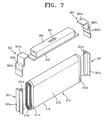
- FIG. 7 illustrates a partial exploded perspective view of the secondary battery of FIG. 6 , wherein a view of a short inducing member is shown in exploded view.
- FIG. 1 illustrates a perspective view of a secondary battery 100 according to an embodiment.
- FIG. 2 illustrates a cross-sectional view taken along a line II-II of FIG. 1 .
- FIG. 3 illustrates a partial exploded perspective view of the secondary battery 100 of FIG. 1 , wherein a view of a short inducing member is shown in exploded view.
- the secondary battery 100 may include an electrode assembly 10 , electrode terminals 21 and 22 , a cap plate 30 , a case 40 , current collectors 50 and 60 , and a short inducing member 70 .
- the secondary battery 100 may be, e.g., a lithium-ion secondary battery having an angular shape.
- the electrode assembly 10 may include a first electrode plate (not illustrated), a separator 13 , and a second electrode plate (not illustrated).
- the current collectors 50 and 60 may be electrically connected to the electrode assembly 10 .
- the current collectors 50 and 60 may include a first current collector 50 and a second current collector 60 electrically connected to the first electrode plate and the second electrode plate, respectively.
- the cap plate 30 may be coupled to an open side of the case 40 so as to seal the case 40 .
- the first electrode plate, the separator 13 , and the second electrode plate may be wound to form a jelly roll shape or configuration.
- the first electrode plate, the separator 13 , and the second electrode plate may be alternatively stacked on each other.
- the short inducing member 70 may be disposed between the first current collector 50 and the second current collector 60 so as to electrically short-circuit the first current collector and the second current collector if the secondary battery is exposed to an external pressure exceeding a predetermined level. When the external pressure exceeds the predetermined level, a shape of the case 40 may be changed and the short inducing member 70 may electrically short-circuit the first current collector and the second current collector.
- the first current collector 50 may contact the first electrode plate at one end of the electrode assembly 10 .
- the second current collector 60 may contact the second electrode plate at another end of the electrode assembly 10 .
- the electrode terminals 21 and 22 may include a first electrode terminal 21 and a second electrode terminal 22 .
- the first electrode terminal 21 may be electrically connected to the first current collector 50 , and may have a part protruding outside of the case 40 through the cap plate 30 .
- the second electrode terminal 22 may be electrically connected to the second current collector 60 , and may have a part protruding outside of the case 40 through the cap plate 30 .
- the first electrode plate may be an anode 11 and the second electrode plate may be a cathode 12 .
- the first current collector 50 may be an anode current collector 50 and the second current collector 60 may be a cathode current collector 60 .
- the first electrode terminal 21 may be an anode terminal 21 and the second electrode terminal 22 may be a cathode terminal 22 .
- the insulating separator 13 may be disposed between the anode 11 and the cathode 12 .
- the anode 11 , the cathode 12 , and the separator 13 may be wound.
- the electrode assembly 10 may be accommodated inside the case 40 .
- the anode terminal 21 and the cathode terminal 22 may be respectively electrically connected to the anode 11 and the cathode 12 of the electrode assembly 10 , and may protrude outside of the case 40 .
- the cap plate 30 may be coupled to the open side of the case 40 .
- the short inducing member 70 may be disposed inside the case 40 .
- the short inducing member 70 may short-circuit the secondary battery according to an external pressure applied to the case 40 .
- the shape of the case 40 may change.
- an external pressure due to, e.g., a crushing force or a shock, applied to the secondary battery exceeds a predetermined level, the short inducing member 70 may electrically short-circuit the anode 11 and the cathode 12 .
- the anode current collector 50 and the cathode current collector 60 When pressure is applied to the case 40 , the anode current collector 50 and the cathode current collector 60 may be pressurized and may move closer to each other. When the external pressure exceeds the predetermined level, the anode current collector 50 and the cathode current collector 60 may contact the short inducing member 70 disposed therebetween. Accordingly, the anode current collector 50 and the cathode current collector 60 may be electrically connected to each other, thereby short circuiting the secondary battery.
- the short inducing member 70 may be disposed in a space between the electrode assembly 10 and the cap plate 30 in the case 40 . Accordingly, when the case 40 deforms, i.e., changes shape, due to pressure applied thereto, the short inducing member 70 inside the case 40 may induce the short.
- the anode 11 and the cathode 12 may be electrically connected through the short inducing member 70 .
- the short inducing member 70 may be formed of, e.g., a material having very low electric resistivity. Accordingly, the short inducing member 70 may generate very little heat during the short, and may quickly allow a large current to pass therethrough.
- the short inducing member 70 may prevent explosion or ignition of the secondary battery 100 due to, e.g., an external shock and/or a crushing force.
- excellent stability and reliability of the secondary battery 100 may be obtained.
- the case 40 may be pressurized in at least one direction of an X-X′, Y-Y′, and Z-Z′ direction illustrated in FIG. 1 . Accordingly, the short inducing member 70 may be configured to induce a short-circuit even when the case 40 is exposed to pressure applied in various directions.
- the anode 11 of the electrode assembly 10 may include an uncoated portion 11 a and a coated portion 11 b .
- the cathode 12 of the electrode assembly 10 may include an uncoated portion 12 a and a coated portion 12 b .
- the uncoated portions 11 a and 12 a may be portions on which an active material is not coated on a current collecting body formed of a thin metal foil.
- the coated portion 11 b and 12 b may be portions on which an active material is coated on the current collecting body.
- the uncoated portion 11 a may be disposed along a lengthwise direction of the anode 11 on a side end of the anode 11 .
- the uncoated portion 12 a may be disposed along a lengthwise direction of the cathode 12 on another side end of the cathode 12 opposite the side end of the anode 11 .
- the electrode assembly 10 may be formed by winding the anode 11 , the cathode 12 , and the separator 13 to form a cylinder. Then, the electrode assembly 10 may be pressed in a plate shape to have a flat portion 18 and a curved portion 19 .
- the flat portion 18 may be formed as a circumferential surface of the electrode assembly 10 is flattened by pressing to form a flat shape.
- the curved portion 19 may be formed due to the unpressed, curved circumferential surfaces of the electrode assembly 10 at each end of the flat portion 18 .
- the short inducing member 70 may extend in a lengthwise direction of the circumference surface of the jelly roll configuration of the electrode assembly 10 .
- the short inducing member 70 may be disposed on the curved portion 19 between the electrode assembly 10 and the cap plate 30 in the case 40 .
- an insulating member e.g., an insulating film 71
- the short inducing member 70 may be attached to the electrode assembly 10 by using an insulating tape.
- the case 40 may have an angular cap shape having one open side.
- the electrode assembly 10 may be accommodated inside the case 40 through the open side of the case 40 along with an electrolyte.
- the cap plate 30 may cover the case 40 while the electrode terminals 21 and 22 may protrude outside of the case 40 through the cap plate 30 .
- a boundary between the case 40 and the cap plate 30 may be welded using, e.g., a laser, and thus the case 40 accommodating the electrode assembly 10 and the electrolyte may be sealed.
- the cap plate 30 may be formed of a thin plate.
- the cap plate 30 may include an electrolyte injecting hole 38 a through which the electrolyte may be injected.
- a sealing plug 38 may be inserted into the electrolyte injecting hole 38 a .
- the cap plate 30 may include a vent member 39 having a groove that may rupture when an internal pressure exceeds a predetermined level.
- the cap plate 30 may include terminal holes 21 a and 22 a penetrating the cap plate 30 .
- the terminal holes 21 a and 22 a may include an anode terminal hole 21 a and a cathode terminal hole 22 a .
- the anode terminal 21 may protrude outside of the case 40 through the anode terminal hole 21 a .
- the cathode terminal 22 may protrude outside of the case 40 through the cathode terminal hole 22 a.
- Gaskets 25 and 27 may be disposed between the cap plate 30 and the electrode terminals 21 and 22 so as to insulate the cap plate 30 and the electrode terminals 21 and 22 .
- the gaskets 25 and 27 may include an upper gasket 25 and a lower gasket 27 .
- the electrode terminals 21 and 22 may include the anode terminal 21 and the cathode terminal 22 .
- the lower gasket 27 may be installed in each of the terminal holes 21 a and 22 a by being inserted therein at the bottom of the cap plate 30 .
- the upper gasket 25 may be installed by being inserted at the top of the cap plate 30 .
- a washer 24 may be installed on the upper gasket 25 so as to absorb a clamping force.
- a screw thread may be formed on each of the anode terminal 21 and the cathode terminal 22 so as to be fastened with a nut 29 .
- the nut 29 may support the electrode terminals 21 and 22 .
- the electrode terminals 21 and 22 may be a rivet type.
- a part of each of the electrode terminals 21 and 22 may protrude to the outside of the case 40 through the terminal holes 21 a and 22 a .
- the protruding parts of the electrode terminals 21 and 22 may be pressurized to be widely flattened while the upper gasket 25 is inserted between the terminal holes 21 a and 22 a and the protruding parts, so as to fix the electrode terminals 21 and 22 to the cap plate 30 .
- the anode current collector 50 may include an anode current collecting plate 51 and an anode lead member 52 .
- the cathode current collector 60 may include a cathode current collecting plate 61 and a cathode lead member 62 .
- the current collecting plates 51 and 61 may include the anode current collecting plate 51 and the cathode current collecting plate 61 .
- the lead members 52 and 62 may include the anode lead member 52 and the cathode lead member 62 .
- the anode current collecting plate 51 may be attached to the uncoated portion 11 a of the electrode assembly 10 by, e.g., welding.
- the anode current collecting plate 51 may be electrically connected to the anode terminal 21 through the anode lead member 52 . Accordingly, the anode terminal 21 may be connected to the anode 11 of the electrode assembly 10 through the anode lead member 52 and the anode current collecting plate 51 .
- the cathode current collecting plate 61 may be attached to the uncoated portion 12 a of the electrode assembly 10 by, e.g., welding.
- the cathode current collecting plate 61 may be electrically connected to the cathode terminal 22 through the cathode lead member 62 .
- the cathode terminal 22 may be connected to the cathode 12 of the electrode assembly 10 through the cathode lead member 62 and the cathode current collecting plate 61 .
- An insulating member 26 may be installed between the lead members 52 and 62 and the cap plate 30 .
- the lead members 52 and 62 may include terminal lead units 52 a and 62 a , current collecting lead units 52 b and 62 b , and bending units 52 c and 62 c .
- the terminal lead units 52 a and 62 a may be respectively attached and electrically connected to the electrode terminals 21 and 22 .
- the current collecting lead units 52 b and 62 b may be respectively attached and electrically connected to the current collecting plates 51 and 61 .
- the bending units 52 c and 62 c may include an anode bending unit 52 c and a cathode bending unit 62 c and may bend above the circumferential surface of the electrode assembly 10 between the terminal lead units 52 a and 62 a and the current collecting lead units 52 b and 62 b . Accordingly, when external pressure exceeding a predetermined level is applied to the case 40 , the shape of the case 40 may change, and the short inducing member 70 may easily contact the anode lead member 52 and the cathode lead member 62 .
- the shape of the case 40 may change. Further, the anode bending unit 52 c and the cathode bending unit 62 c may slide on the electrode assembly 10 on which the insulating film 71 is disposed. Thus, the anode lead member 52 and the cathode lead member 62 may be electrically short-circuited through the short inducing member 70 .
- the anode lead member 52 and the cathode lead member 62 are illustrated as respectively including the bending units 52 c and 62 c .
- either of the bending units 52 c and 62 c may be included in the anode lead member 52 or the cathode lead member 62 .
- the anode terminal 21 or the cathode terminal 22 may not include the upper gasket 25 , the insulating member 26 , and the lower gasket 27 for electrically separating the cap plate 30 and the anode 11 or for electrically separating the cap plate 30 and the cathode 12 .
- the upper gasket 25 and the lower gasket 27 may not be installed between the anode terminal 21 and the cap plate 30 , and the insulating member 26 may not be installed between the anode lead member 52 of the anode terminal 21 and the cap plate 30 .
- the anode terminal 21 may contact the cap plate 30 by directly penetrating through the anode terminal hole 21 a without the upper gasket 25 and the lower gasket 27 . Further, the anode lead member 52 may directly contact the cap plate 30 . Accordingly, the cap plate 30 and the case 40 may have the same polarity as the anode terminal 21 .
- the secondary battery 100 may be, e.g., a lithium-ion battery, but is not limited thereto.
- the secondary battery 100 may be, e.g., a nickel-cadmium battery, a nickel-hydrogen battery, or other batteries including a lithium battery.
- the secondary battery 100 may have an angular shape.
- the shape of the secondary battery 100 is not limited thereto, and may have different shapes, e.g., a cylindrical shape or a pouch shape.
- the short inducing member 70 may have a predetermined thickness, and may have a thin plate shape extending in a lengthwise direction of the jelly roll structure of the electrode assembly 10 .
- the case 40 When external pressure is not applied to the secondary battery, i.e., in a normal state of operation, the case 40 may retain its original shape, an the short inducing member 70 may be electrically isolated from the anode current collector 50 and the cathode current collector 60 .
- the shape of the case 40 When external pressure that exceeds a predetermined level is applied to the secondary battery, the shape of the case 40 may change, and the short inducing member 70 may be electrically connected to the electrode assembly 10 through the lead members 52 and 62 and the current collecting plates 51 and 61 , thereby short-circuiting the anode 11 and the cathode 12 .
- the short inducing member 70 when external pressure is not applied to the secondary battery, i.e., in a normal state of operation, the short inducing member 70 may be electrically connected to one of the anode current collector 50 and the cathode current collector 60 and may be electrically isolated from the other.
- the short inducing member 70 may be, e.g., attached to or integrated as one body with, whichever of the anode current collector 50 and the cathode current collector 60 that is electrically connected to the short inducing member 70 , by, e.g., welding or a similar method.
- An amount of pressure that induces a short by the short inducing member 70 may be determined on an experimental basis.
- a distance between the short inducing member 70 and the anode current collector 50 and/or a distance between the short inducing member 70 and the cathode current collector 60 may be selected in such a way that a short may be induced according to a predetermined pressure applied to the case 40 .
- the predetermined level of external pressure required to induce a short in the secondary battery may be determined according to a size, shape, and location, i.e., configuration, of the short inducing member 70 relative to the anode current collector 50 and/or the cathode current collector 60 .
- the short inducing member 70 may be formed of a material having very low electric resistivity.
- the short inducing member 70 may be formed of a metallic material having low resistivity, e.g., copper (Cu), aluminum (Al), and/or iron (Fe).
- the short inducing member 70 may be formed of the same material as the anode lead member 52 or the cathode lead member 62 .
- the anode 11 , the anode current collecting plate 51 , and the anode lead member 52 , which may be electrically connected to each other, may all include the same material, e.g., aluminum.
- the cathode 12 , the cathode current collecting plate 61 , and the cathode lead member 62 which may be electrically connected to each other, may all include the same material, e.g., copper.
- the short inducing member 70 may include, e.g., copper, which has a lower electric resistivity than aluminum.
- the short inducing member 70 may be formed of a material having low electric resistivity, the short inducing member 70 may generate little heat during a short and may quickly let a large current flow. Accordingly, the short inducing member 70 may prevent explosion and/or ignition of the secondary battery 100 due to, e.g., an external shock or crushing. Thus, excellent stability and reliability of the secondary battery 100 may be obtained.
- the electrode assembly 10 may be pressed flat to form a plate shape after being wound, and may have an internal space 14 at the center thereof.
- the current collecting plates 51 and 61 may respectively include supporting protrusions 51 b and 61 b , which may be inserted into the internal space 14 .
- current collecting plates 51 and 61 may also respectively include attached plates 51 a and 61 a , which may be welded to sides of the electrode assembly 10 after being pressed against the uncoated portions 11 a and 12 a.
- the supporting protrusions 51 b and 61 b may extend from a center of the current collecting plates 51 and 61 along a lengthwise direction of the current collecting plates 51 and 61 . Heights of the supporting protrusions 51 b and 61 b may correspond to a height of the internal space 14 of the electrode assembly 10 .
- the supporting protrusions 51 b and 61 b may support the electrode assembly 10 by being inserted into the internal space 14 of the electrode assembly 10 . Accordingly, the supporting protrusions 51 b and 61 b may ensure good contact between the electrode assembly 10 and the current collecting plates 51 and 61 even in the event of an external shock.
- the supporting protrusions 51 b and 61 b may not only support the electrode assembly 10 in the lengthwise direction of the internal space 14 but also in a width direction, and thus may stably support the electrode assembly 10 .
- the attached plates 51 a and 61 a may be connected to edges of the respective supporting protrusions 51 b and 61 b .
- the attached plates 51 a and 61 a may contact side ends of the electrode assembly 10 .
- the uncoated portions 11 a and 12 a disposed at the side ends of the electrode assembly 10 may be pressed by the attached plates 51 a and 61 a .
- the side ends may denote a side surface vertical to a central axis when the electrode assembly 10 is wound.
- the attached plates 51 a and 61 a and the uncoated portions 11 a and 12 a may contact each other over a wide area.
- the attached plates 51 a and 61 a may be attached to the side ends of the electrode assembly 10 by, e.g., laser welding.
- thicknesses of the current collecting plates 51 and 61 may be thicker compared to when ultrasonic welding is used.
- resistance within the current collecting plates 51 and 61 may be advantageously reduced.
- an overall output of the electrode assembly 10 may be increased by decreasing areas of the uncoated portions 11 a and 12 a and increasing areas of the coated portions 11 b and 12 b.
- excellent stability and reliability of the secondary battery 100 may be obtained by preventing an explosion in a pressurized environment due to, e.g., a crushing force or a shock.
- FIG. 4 illustrates a sectional view of a secondary battery 200 according to another embodiment.
- FIG. 5 illustrates a partial exploded perspective view of the secondary battery 200 of FIG. 4 , wherein a view of a short inducing member 270 is shown in exploded view.
- the short inducing member 270 may be electrically connected to one of an anode current collector 250 or a cathode current collector 260 and may be electrically isolated from the other thereof.
- elements of the secondary battery 200 which are identical to the secondary battery 100 of FIGS. 1 , 2 and 3 , have similar reference numerals as the elements of the secondary battery 100 , and repeated detailed descriptions thereof are omitted.
- the case 240 may retain its original shape, and the short inducing member 270 may be electrically connected to the cathode current collector 260 and may be electrically isolated from the anode current collector 250 .
- the short inducing member 270 may be attached to or integrated as one body with the cathode current collector 260 by; e.g., welding or a similar method.
- an insulating member e.g., an insulating film 271 , may be disposed between the short inducing member 270 and the electrode assembly 210 .
- the short inducing member 270 may not be attached to the electrode assembly 210 .
- the short inducing member 270 may slide on the electrode assembly 210 when an external pressure is applied.
- the short inducing member 270 may include a material identical to a material of a cathode lead member 262 and having small electric resistivity, e.g., copper. When the short inducing member 270 is formed of the same material as the cathode lead member 262 , the short inducing member 270 may be easily attached to the cathode lead member 262 since items of the same material may be more easily welded together.
- the case 240 when no external pressure is applied, i.e., in a normal state of operation, the case 240 may retain its original shape, and the short inducing member 270 may be electrically connected to the anode current collector 250 and electrically isolated from the cathode current collector 260 .
- the short inducing member 270 may be attached to or integrated as one body with the anode current collector 250 by, e.g., welding.
- the secondary battery 200 may include the electrode assembly 210 , electrode terminals 221 and 222 , a cap plate 230 , a case 240 , current collectors 250 and 260 , and the short inducing member 270 .
- the electrode assembly 210 may be formed by disposing an insulating separator 213 between an anode 211 and a cathode 212 .
- the case 240 may accommodate the electrode assembly 210 therein.
- the electrode terminals 221 and 222 respectively include an anode terminal 221 and a cathode terminal 222 .
- the anode terminal 221 and the cathode terminal 222 may protrude outside of the case 240 and may be respectively electrically connected to the anode 211 and the cathode 212 of the electrode assembly 210 .
- the cap plate 230 may be coupled to an open side of the case 240 .
- the current collectors 250 and 260 may include the anode current collector 250 and the cathode current collector 260 and may be respectively electrically connected to the anode 211 and the cathode 212 .
- the short inducing member 270 may be disposed between the anode current collector 250 and the cathode current collector 260 so as to electrically short-circuit the anode current collector 250 and the cathode current collector 260 if the secondary battery is exposed to an external pressure exceeding a predetermined level or a pressure of a level sufficient to change the shape of the case 240 . Accordingly, excellent stability and reliability of the secondary battery 200 may be obtained by preventing explosion and/or ignition of the secondary battery 200 due to an external shock or crushing.
- the anode 211 may include an anode uncoated portion 211 a and an anode coated portion 211 b .
- the cathode 212 may include a cathode uncoated portion 212 a and a cathode coated portion 212 b .
- the anode terminal 221 may protrude outside of the case 240 through an anode terminal hole 221 a
- the cathode terminal 222 may protrude outside of the case 240 through a cathode terminal hole 222 a.
- An electrolyte injecting hole 238 a may be formed on the cap plate 230 .
- a sealing plug 238 may be inserted in the electrolyte injecting hole 238 a .
- a vent member 239 may be installed on the cap plate 230 .
- An upper gasket 225 and a lower gasket 227 may be disposed between the cap plate 230 and the anode terminal 221 and the cathode terminal 222 so as to insulate the cap plate 230 and the anode terminal 221 and the cathode terminal 222 .
- a washer 224 for buffering, i.e., absorbing, a clamping force may be installed on the upper gasket 225 .
- the anode terminal 221 and the cathode terminal 222 may be fastened to a nut 229 .
- the anode terminal 221 and the cathode terminal 222 may be a rivet type.
- An anode current collecting plate 251 and a cathode current collecting plate 261 may be respectively attached to the anode uncoated portion 211 a and the cathode uncoated portion 212 a of the electrode assembly 210 by, e.g., welding.
- the anode current collecting plate 251 may be electrically connected to the anode terminal 221 through an anode lead member 252 .
- the cathode current collecting plate 261 may be electrically connected to the cathode terminal 222 through the cathode lead member 262 .
- An insulating member 226 may be disposed between the anode lead member 252 and the cap plate 230 and between the cathode lead member 262 and the cap plate 230 .
- the insulating member 226 may be disposed between the lead members 252 and 262 and the cap plate 230 .
- the lead members 252 and 262 may include terminal lead units 252 a and 262 a , and current collecting lead units 252 b and 262 b .
- the anode lead member 252 may include a bending unit 252 c .
- the terminal lead units 252 a and 262 a may be respectively attached to and electrically connected to the electrode terminals 221 and 222 .
- the current collecting lead units 252 b and 262 b may be attached and electrically connected to the current collecting plates 251 and 261 .
- the bending unit 252 c may be bent over a circumferential surface of the electrode assembly 210 between an anode terminal lead unit 252 a and an anode current collecting lead unit 252 b .
- the short inducing member 270 may be attached to or integrated as one body with the cathode current collecting lead unit 262 b while facing the anode current collecting lead unit 262 a.
- the short inducing member 270 may easily contact the anode lead member 252 .
- the cathode lead member 262 may include a bending unit instead of the anode lead member 252 .
- both of the anode lead member 252 and the cathode lead member 262 may include a bending unit.
- stability and reliability of the secondary battery 200 may be obtained by preventing an explosion in a pressurized environment caused by, e.g., a crushing force or a shock.
- FIG. 6 illustrates a perspective view of a secondary battery 300 according to yet another embodiment.
- FIG. 7 illustrates a partial exploded perspective view of the secondary battery 300 of FIG. 6 , wherein a view of a short inducing member 370 is shown in exploded view.
- the short inducing member 370 may be attached to a surface of a degassing duct 380 , which may face an electrode assembly 310 .
- FIGS. 6 and 7 elements of the secondary battery 300 that are identical to the secondary battery 100 of FIGS. 1 , 2 and 3 have similar reference numerals as the elements of the secondary battery 100 . Accordingly, repeated detailed descriptions thereof is omitted.
- the degassing duct 380 may be disposed between a cap plate 330 and the short inducing member 370 so as to form a gas passage.
- the degassing duct 380 may form a gas passage by being disposed between the cap plate 330 and the electrode assembly 310 .
- the short inducing member 370 may be attached to a bottom surface of the degassing duct 380 , which may face the electrode assembly 310 . Accordingly, the degassing duct 380 may support the electrode assembly 310 with respect to the cap plate 330 . In an implementation, the degassing duct 380 may be formed of an insulating material.
- the degassing duct 380 may effectively support the electrode assembly 310 .
- the short inducing member 370 may be supported on the electrode assembly 310 without using an adhesive tape.
- the short inducing member 370 may be attached to the electrode assembly 310 by using an insulating tape. In an implementation, the short inducing member 370 may be firmly supported on the electrode assembly 310 .
- an insulating member e.g., an insulating film 371 , may be disposed between the short inducing member 370 and, the electrode assembly 310 .
- the short inducing member 370 When no external pressure is applied, i.e., in a normal state of operation, the short inducing member 370 may be electrically isolated from an anode current collector 350 and a cathode current collector 360 . When external pressure is applied, e.g., above a predetermined level or a level sufficient to change the shape of the case 340 , the short inducing member 370 may be electrically connected to the electrode assembly 310 through lead members 352 and 362 and current collecting plates 351 and 361 , thereby short-circuiting the anode 311 and the cathode 312 .
- the short inducing member 370 when no external pressure is applied, i.e., in a normal state of operation, the short inducing member 370 may be electrically connected to one of the anode current collector 350 or the cathode current collector 350 , and may be electrically isolated from the other.
- the short inducing member 370 may be attached to or integrated as one body with whichever of the anode current collector 350 and the cathode current collector 35 that is connected to the short inducing member 370 by using, e.g., welding.
- the short inducing member 370 may be formed of the same material as the anode lead member 352 or the cathode lead member 362 .
- the short inducing member 370 may be formed of a material having low electric resistivity.
- the short inducing member 370 may be formed of a metallic material having low resistivity, e.g., copper, aluminum, and/or iron and in a particular implementation; the short inducing member 370 may include material having low electric resistivity, e.g., copper.
- the short inducing member 370 may be formed of a material having low electric resistivity, the short inducing member 370 may generate little heat during a short and may quickly let a large current flow. Accordingly, the short inducing member 370 may prevent explosion and/or ignition of the secondary battery 300 due to, e.g., an external shock or crushing. Thus, excellent stability and reliability of the secondary battery 300 may be obtained.
- the secondary battery 300 may include the electrode assembly 310 , electrode terminals 321 and 322 , the cap plate 330 , a case 340 , current collectors 350 and 360 , and the short inducing member 370 .
- the electrode assembly 310 may be formed by disposing a separator 313 constituting an insulator between the anode 311 and the cathode 312 .
- the case 340 may accommodate the electrode assembly 310 therein.
- the electrode terminals 321 and 322 may respectively include an anode terminal 321 and a cathode terminal 322 .
- the anode terminal 321 and the cathode terminal 322 may protrude outside of the case 340 and may be respectively electrically connected to the anode 311 and the cathode 312 of the electrode assembly 310 .
- the cap plate 330 may be coupled to an open side of the case 340 .
- the current collectors 350 and 360 may respectively include the anode current collector 350 and the cathode current collector 360 , which may be respectively electrically connected to the anode 311 and the cathode 312 .
- the short inducing member 370 may be disposed between the anode current collector 350 and the cathode current collector 360 , thereby electrically short-circuiting the anode current collector 350 and the cathode current collector 360 when an external pressure exceeds a predetermined level or a level sufficient to change the shape of the case 340 . Accordingly, excellent stability and reliability of the secondary battery 300 are obtained by preventing the secondary battery from exploding and/or igniting due to an external shock or crushing.
- the anode 311 may include an anode uncoated portion 311 a and an anode coated portion 311 b .
- the cathode 312 may include a cathode uncoated portion 312 a and a cathode coated portion 312 b .
- the anode terminal 321 may protrude outside of the case 340 through an anode terminal hole 321 a .
- the cathode terminal 322 may protrude outside of the case 340 through a cathode terminal hole 322 a.
- the cap plate 330 may include an electrolyte injecting hole 338 a , a sealing plug 338 in the electrolyte injecting hole 338 a , and a vent member 339 on the cap plate 330 .
- the degassing duct 380 may include a gas outlet 381 for exhausting gas at a location corresponding to the vent member 339 . In other words, the degassing duct 380 may be disposed below the vent member 339 .
- An upper gasket 325 and a lower gasket 327 may each be disposed between the cap plate 330 and the anode terminal 321 and the cathode terminal 322 , so as to insulate the cap plate 330 and the anode terminal 321 and the cathode terminal 322 .
- a washer 324 for buffering, i.e., absorbing, a clamping force may be installed on the upper gasket 325 .
- the anode terminal 321 and the cathode terminal 322 may be fastened with a nut 329 .
- the anode terminal 321 and the cathode terminal 322 may be a rivet type.
- An anode current collecting plate 351 and a cathode current collecting plate 361 may be respectively attached to the anode uncoated portion 311 a and the cathode uncoated portion 312 a of the electrode assembly 310 by, e.g., welding.
- the anode current collecting plate 351 may be electrically connected to the anode terminal 321 through the anode lead member 352 .
- the cathode current collecting plate 361 may be electrically connected to the cathode terminal 322 through the cathode lead member 352 .
- An insulating member 326 may be installed between the cap plate 330 and the anode lead member 352 and the cathode lead member 362 .
- the insulating member 326 may be installed between the lead members 352 and 362 and the cap plate 330 .
- the lead members 352 and 362 may include terminal lead units 352 a and 362 a , current collecting lead units 352 b and 362 b , and at least one bending unit 352 c and/or 362 c .
- the terminal lead units 352 a and 362 a may be respectively attached to and electrically connected to the electrode terminals 321 and 322 .
- the current collecting lead units 352 b and 362 b may be respectively attached and electrically connected to the current collecting plates 351 and 361 .
- the bending units 352 c and 362 c may be bent over a circumferential surface of the electrode assembly 310 between the terminal lead units 352 a and 362 a and the current collecting lead units 352 b and 362 b . Accordingly, when an applied external pressure exceeds a predetermined level, the short inducing member 370 may easily contact the anode lead member 352 and the cathode lead member 362 . Thus, when the applied external pressure exceeds the predetermined level or a level sufficient to change the shape of the case 340 , the short inducing member 370 may easily contact the anode lead member 352 .
- a bending unit may be installed only in the cathode lead member 362 , or only in the anode lead member 352 .
- excellent stability and reliability of the secondary battery 300 may be obtained by preventing an explosion in a pressurized environment caused by a crushing force or a shock.
Landscapes
- Chemical & Material Sciences (AREA)
- Chemical Kinetics & Catalysis (AREA)
- Electrochemistry (AREA)
- General Chemical & Material Sciences (AREA)
- Engineering & Computer Science (AREA)
- Manufacturing & Machinery (AREA)
- Connection Of Batteries Or Terminals (AREA)
Abstract
Description
Claims (19)
Applications Claiming Priority (2)
| Application Number | Priority Date | Filing Date | Title |
|---|---|---|---|
| KR1020090104307A KR101097220B1 (en) | 2009-10-30 | 2009-10-30 | Secondary battery |
| KR10-2009-0104307 | 2009-10-30 |
Publications (2)
| Publication Number | Publication Date |
|---|---|
| US20110104528A1 US20110104528A1 (en) | 2011-05-05 |
| US9028993B2 true US9028993B2 (en) | 2015-05-12 |
Family
ID=43567543
Family Applications (1)
| Application Number | Title | Priority Date | Filing Date |
|---|---|---|---|
| US12/805,743 Active 2033-02-26 US9028993B2 (en) | 2009-10-30 | 2010-08-18 | Secondary battery |
Country Status (3)
| Country | Link |
|---|---|
| US (1) | US9028993B2 (en) |
| EP (1) | EP2325924B1 (en) |
| KR (1) | KR101097220B1 (en) |
Families Citing this family (14)
| Publication number | Priority date | Publication date | Assignee | Title |
|---|---|---|---|---|
| KR101256060B1 (en) | 2011-06-02 | 2013-04-18 | 로베르트 보쉬 게엠베하 | Rechargeable battery |
| CN202495505U (en) | 2011-11-25 | 2012-10-17 | 深圳市比亚迪锂电池有限公司 | Electrical connecting piece and battery |
| KR101715963B1 (en) | 2012-04-06 | 2017-03-27 | 삼성에스디아이 주식회사 | Secondary bttery |
| KR101715964B1 (en) * | 2012-06-04 | 2017-03-13 | 삼성에스디아이 주식회사 | Rechargeable secondary battery |
| CN202905820U (en) * | 2012-10-19 | 2013-04-24 | 宁德时代新能源科技有限公司 | Lithium ion battery adopting safety protection bracket |
| JP6173729B2 (en) * | 2013-03-14 | 2017-08-02 | 株式会社東芝 | Battery manufacturing method |
| CN104078631B (en) * | 2013-03-27 | 2019-03-08 | 株式会社杰士汤浅国际 | Charge storage element and electrical storage device |
| DE102013210323A1 (en) * | 2013-06-04 | 2014-12-04 | Robert Bosch Gmbh | Battery system and vehicle with battery system |
| KR20150053597A (en) * | 2013-11-08 | 2015-05-18 | 삼성에스디아이 주식회사 | Battery Module |
| JP6750438B2 (en) * | 2016-09-30 | 2020-09-02 | 三洋電機株式会社 | Prismatic secondary battery |
| CN109844995B (en) * | 2016-09-30 | 2022-06-17 | 三洋电机株式会社 | Prismatic secondary battery and method for manufacturing same |
| JP7245044B2 (en) * | 2018-12-25 | 2023-03-23 | 本田技研工業株式会社 | Solid-state battery cell structure and solid-state battery manufacturing method |
| JP7304372B2 (en) | 2021-01-28 | 2023-07-06 | プライムプラネットエナジー&ソリューションズ株式会社 | secondary battery |
| KR20230149499A (en) * | 2022-04-20 | 2023-10-27 | 삼성에스디아이 주식회사 | Secondary Battery |
Citations (9)
| Publication number | Priority date | Publication date | Assignee | Title |
|---|---|---|---|---|
| JP2004319463A (en) | 2003-03-28 | 2004-11-11 | Matsushita Electric Ind Co Ltd | Rechargeable battery |
| EP1487032A1 (en) | 2002-02-13 | 2004-12-15 | Matsushita Electric Industrial Co., Ltd. | Battery pack manufacturing method |
| US6838207B1 (en) * | 1999-03-19 | 2005-01-04 | Sanyo Electric Co., Ltd. | Sealed battery with less electrolyte leakage |
| KR20050121907A (en) | 2004-06-23 | 2005-12-28 | 삼성에스디아이 주식회사 | Secondary battery and electrodes assembly using the same |
| EP1717886A2 (en) | 2005-04-25 | 2006-11-02 | Samsung SDI Co., Ltd. | Can type lithium secondary battery |
| US20070054157A1 (en) | 2005-09-07 | 2007-03-08 | Ryu Ji H | Secondary battery employing safety device |
| JP2008041264A (en) | 2006-08-01 | 2008-02-21 | Sony Corp | Battery and short circuit member |
| US20100279170A1 (en) * | 2009-08-27 | 2010-11-04 | Donghyun Lee | Rechargeable secondary battery having improved safety against puncture and collapse |
| US20110052949A1 (en) * | 2009-09-01 | 2011-03-03 | Sang-Won Byun | Rechargeable battery |
-
2009
- 2009-10-30 KR KR1020090104307A patent/KR101097220B1/en active Active
-
2010
- 2010-08-18 US US12/805,743 patent/US9028993B2/en active Active
- 2010-10-29 EP EP10189339.4A patent/EP2325924B1/en active Active
Patent Citations (10)
| Publication number | Priority date | Publication date | Assignee | Title |
|---|---|---|---|---|
| US6838207B1 (en) * | 1999-03-19 | 2005-01-04 | Sanyo Electric Co., Ltd. | Sealed battery with less electrolyte leakage |
| EP1487032A1 (en) | 2002-02-13 | 2004-12-15 | Matsushita Electric Industrial Co., Ltd. | Battery pack manufacturing method |
| JP2004319463A (en) | 2003-03-28 | 2004-11-11 | Matsushita Electric Ind Co Ltd | Rechargeable battery |
| KR20050121907A (en) | 2004-06-23 | 2005-12-28 | 삼성에스디아이 주식회사 | Secondary battery and electrodes assembly using the same |
| US20050287429A1 (en) | 2004-06-23 | 2005-12-29 | Kyu-Woong Cho | Rechargeable battery |
| EP1717886A2 (en) | 2005-04-25 | 2006-11-02 | Samsung SDI Co., Ltd. | Can type lithium secondary battery |
| US20070054157A1 (en) | 2005-09-07 | 2007-03-08 | Ryu Ji H | Secondary battery employing safety device |
| JP2008041264A (en) | 2006-08-01 | 2008-02-21 | Sony Corp | Battery and short circuit member |
| US20100279170A1 (en) * | 2009-08-27 | 2010-11-04 | Donghyun Lee | Rechargeable secondary battery having improved safety against puncture and collapse |
| US20110052949A1 (en) * | 2009-09-01 | 2011-03-03 | Sang-Won Byun | Rechargeable battery |
Non-Patent Citations (2)
| Title |
|---|
| European Search Report in EP 10189339.4-2119, dated Mar. 3, 2011 (Byun, et al.). |
| Korean Office Action in KR 10-2009-0104307, dated Mar. 22, 2011 (Byun, et al.). |
Also Published As
| Publication number | Publication date |
|---|---|
| KR20110047610A (en) | 2011-05-09 |
| KR101097220B1 (en) | 2011-12-21 |
| EP2325924A1 (en) | 2011-05-25 |
| US20110104528A1 (en) | 2011-05-05 |
| EP2325924B1 (en) | 2013-04-24 |
Similar Documents
| Publication | Publication Date | Title |
|---|---|---|
| US9028993B2 (en) | Secondary battery | |
| EP2362466B1 (en) | Rechargeable battery with short circuit inducing members | |
| US9023516B2 (en) | Rechargeable battery and module thereof | |
| KR100496305B1 (en) | Pouched-type lithium secondary battery and the fabrication method thereof | |
| JP5345633B2 (en) | Secondary battery pack with precise structure | |
| KR101097221B1 (en) | Secondary battery | |
| US9136523B2 (en) | Rechargeable battery | |
| US9236595B2 (en) | Secondary battery | |
| EP2348558A1 (en) | Rechargeable battery | |
| US20110104562A1 (en) | Secondary battery | |
| US20100151317A1 (en) | Rechargeable battery | |
| US20100233519A1 (en) | Rechargeable battery | |
| CN101950812A (en) | Rechargeable battery | |
| US20140272520A1 (en) | Battery module | |
| JP5203729B2 (en) | Secondary battery and battery module | |
| US9059456B2 (en) | Rechargeable battery and battery module | |
| KR20140124247A (en) | Rechargeable battery | |
| EP2571074A1 (en) | Rechargeable battery | |
| US20110287310A1 (en) | Rechargeable battery | |
| US8877371B2 (en) | Rechargeable battery | |
| KR101121205B1 (en) | Secondary battery | |
| US9520579B2 (en) | Rechargeable battery | |
| US8492014B2 (en) | Secondary battery | |
| CN120432669A (en) | Electrode assembly and secondary battery including the same |
Legal Events
| Date | Code | Title | Description |
|---|---|---|---|
| AS | Assignment |
Owner name: SB LIMOTIVE CO., LTD., KOREA, REPUBLIC OF Free format text: ASSIGNMENT OF ASSIGNORS INTEREST;ASSIGNORS:BYUN, SANG-WON;YOO, SOO-KYOUNG;SHIM, HEUNG-TACK;AND OTHERS;REEL/FRAME:024901/0972 Effective date: 20100719 |
|
| AS | Assignment |
Owner name: SAMSUNG SDI CO., LTD., KOREA, REPUBLIC OF Free format text: ASSIGNMENT OF ASSIGNORS INTEREST;ASSIGNOR:SB LIMOTIVE CO. LTD.;REEL/FRAME:029584/0111 Effective date: 20121130 Owner name: ROBERT BOSCH GMBH, GERMANY Free format text: ASSIGNMENT OF ASSIGNORS INTEREST;ASSIGNOR:SB LIMOTIVE CO. LTD.;REEL/FRAME:029584/0111 Effective date: 20121130 |
|
| STCF | Information on status: patent grant |
Free format text: PATENTED CASE |
|
| MAFP | Maintenance fee payment |
Free format text: PAYMENT OF MAINTENANCE FEE, 4TH YEAR, LARGE ENTITY (ORIGINAL EVENT CODE: M1551); ENTITY STATUS OF PATENT OWNER: LARGE ENTITY Year of fee payment: 4 |
|
| MAFP | Maintenance fee payment |
Free format text: PAYMENT OF MAINTENANCE FEE, 8TH YEAR, LARGE ENTITY (ORIGINAL EVENT CODE: M1552); ENTITY STATUS OF PATENT OWNER: LARGE ENTITY Year of fee payment: 8 |