EP3483853B1 - Drahtlose smarthome-bedienvorrichtung - Google Patents
Drahtlose smarthome-bedienvorrichtung Download PDFInfo
- Publication number
- EP3483853B1 EP3483853B1 EP18203026.2A EP18203026A EP3483853B1 EP 3483853 B1 EP3483853 B1 EP 3483853B1 EP 18203026 A EP18203026 A EP 18203026A EP 3483853 B1 EP3483853 B1 EP 3483853B1
- Authority
- EP
- European Patent Office
- Prior art keywords
- control element
- macro
- smart home
- portable
- stationary
- Prior art date
- Legal status (The legal status is an assumption and is not a legal conclusion. Google has not performed a legal analysis and makes no representation as to the accuracy of the status listed.)
- Active
Links
Images



Classifications
-
- G—PHYSICS
- G08—SIGNALLING
- G08C—TRANSMISSION SYSTEMS FOR MEASURED VALUES, CONTROL OR SIMILAR SIGNALS
- G08C17/00—Arrangements for transmitting signals characterised by the use of a wireless electrical link
- G08C17/02—Arrangements for transmitting signals characterised by the use of a wireless electrical link using a radio link
-
- F—MECHANICAL ENGINEERING; LIGHTING; HEATING; WEAPONS; BLASTING
- F16—ENGINEERING ELEMENTS AND UNITS; GENERAL MEASURES FOR PRODUCING AND MAINTAINING EFFECTIVE FUNCTIONING OF MACHINES OR INSTALLATIONS; THERMAL INSULATION IN GENERAL
- F16M—FRAMES, CASINGS OR BEDS OF ENGINES, MACHINES OR APPARATUS, NOT SPECIFIC TO ENGINES, MACHINES OR APPARATUS PROVIDED FOR ELSEWHERE; STANDS; SUPPORTS
- F16M11/00—Stands or trestles as supports for apparatus or articles placed thereon ; Stands for scientific apparatus such as gravitational force meters
- F16M11/02—Heads
- F16M11/04—Means for attachment of apparatus; Means allowing adjustment of the apparatus relatively to the stand
- F16M11/041—Allowing quick release of the apparatus
-
- F—MECHANICAL ENGINEERING; LIGHTING; HEATING; WEAPONS; BLASTING
- F16—ENGINEERING ELEMENTS AND UNITS; GENERAL MEASURES FOR PRODUCING AND MAINTAINING EFFECTIVE FUNCTIONING OF MACHINES OR INSTALLATIONS; THERMAL INSULATION IN GENERAL
- F16M—FRAMES, CASINGS OR BEDS OF ENGINES, MACHINES OR APPARATUS, NOT SPECIFIC TO ENGINES, MACHINES OR APPARATUS PROVIDED FOR ELSEWHERE; STANDS; SUPPORTS
- F16M11/00—Stands or trestles as supports for apparatus or articles placed thereon ; Stands for scientific apparatus such as gravitational force meters
- F16M11/02—Heads
- F16M11/04—Means for attachment of apparatus; Means allowing adjustment of the apparatus relatively to the stand
- F16M11/06—Means for attachment of apparatus; Means allowing adjustment of the apparatus relatively to the stand allowing pivoting
- F16M11/10—Means for attachment of apparatus; Means allowing adjustment of the apparatus relatively to the stand allowing pivoting around a horizontal axis
- F16M11/105—Means for attachment of apparatus; Means allowing adjustment of the apparatus relatively to the stand allowing pivoting around a horizontal axis the horizontal axis being the roll axis, e.g. for creating a landscape-portrait rotation
-
- F—MECHANICAL ENGINEERING; LIGHTING; HEATING; WEAPONS; BLASTING
- F16—ENGINEERING ELEMENTS AND UNITS; GENERAL MEASURES FOR PRODUCING AND MAINTAINING EFFECTIVE FUNCTIONING OF MACHINES OR INSTALLATIONS; THERMAL INSULATION IN GENERAL
- F16M—FRAMES, CASINGS OR BEDS OF ENGINES, MACHINES OR APPARATUS, NOT SPECIFIC TO ENGINES, MACHINES OR APPARATUS PROVIDED FOR ELSEWHERE; STANDS; SUPPORTS
- F16M13/00—Other supports for positioning apparatus or articles; Means for steadying hand-held apparatus or articles
-
- F—MECHANICAL ENGINEERING; LIGHTING; HEATING; WEAPONS; BLASTING
- F16—ENGINEERING ELEMENTS AND UNITS; GENERAL MEASURES FOR PRODUCING AND MAINTAINING EFFECTIVE FUNCTIONING OF MACHINES OR INSTALLATIONS; THERMAL INSULATION IN GENERAL
- F16M—FRAMES, CASINGS OR BEDS OF ENGINES, MACHINES OR APPARATUS, NOT SPECIFIC TO ENGINES, MACHINES OR APPARATUS PROVIDED FOR ELSEWHERE; STANDS; SUPPORTS
- F16M13/00—Other supports for positioning apparatus or articles; Means for steadying hand-held apparatus or articles
- F16M13/02—Other supports for positioning apparatus or articles; Means for steadying hand-held apparatus or articles for supporting on, or attaching to, an object, e.g. tree, gate, window-frame, cycle
-
- F—MECHANICAL ENGINEERING; LIGHTING; HEATING; WEAPONS; BLASTING
- F24—HEATING; RANGES; VENTILATING
- F24F—AIR-CONDITIONING; AIR-HUMIDIFICATION; VENTILATION; USE OF AIR CURRENTS FOR SCREENING
- F24F11/00—Control or safety arrangements
- F24F11/50—Control or safety arrangements characterised by user interfaces or communication
- F24F11/52—Indication arrangements, e.g. displays
-
- G—PHYSICS
- G06—COMPUTING OR CALCULATING; COUNTING
- G06F—ELECTRIC DIGITAL DATA PROCESSING
- G06F1/00—Details not covered by groups G06F3/00 - G06F13/00 and G06F21/00
- G06F1/16—Constructional details or arrangements
- G06F1/1613—Constructional details or arrangements for portable computers
- G06F1/1632—External expansion units, e.g. docking stations
-
- G—PHYSICS
- G08—SIGNALLING
- G08C—TRANSMISSION SYSTEMS FOR MEASURED VALUES, CONTROL OR SIMILAR SIGNALS
- G08C2201/00—Transmission systems of control signals via wireless link
- G08C2201/30—User interface
-
- G—PHYSICS
- G08—SIGNALLING
- G08C—TRANSMISSION SYSTEMS FOR MEASURED VALUES, CONTROL OR SIMILAR SIGNALS
- G08C23/00—Non-electrical signal transmission systems, e.g. optical systems
- G08C23/04—Non-electrical signal transmission systems, e.g. optical systems using light waves, e.g. infrared
Definitions
- a wireless smart home operating device with at least one stationary element, with at least one portable operating element and with at least one coupling unit for coupling the stationary element to the portable operating element has already been proposed.
- U.S. 2017/059196 A1 discloses the features of the preamble of claim 1: a wireless smart home operating device (102), at least for operating a smart home functional unit (cf. paragraphs [0048], [0051] and [0053]), with at least one stationary element (542) , with at least one portable operating element (540) and with at least one coupling unit for a physical coupling of the stationary element (542) with the portable operating element (540) (cf. Para. [0073]).
- the portable control element (540) forms a macro control element, the macro control element having at least one rotation detection module, at least for detecting a rotational position of at least one part (512, 514) of the macro control element (cf. para.
- an operating procedure of the macro control element at least partially comprises an at least partial rotation of at least one part (512) of the macro control element relative to at least one further part (514) of the macro control element (cf. paragraph [0002] and FIG. 5A).
- the invention is based on a wireless smart home operating device, in particular at least for operating at least one lamp, an alarm system, a thermostat, a switchable socket outlet or the like, with at least one stationary element, with at least one portable operating element and with at least one coupling unit to form one , In particular physical coupling of the stationary element with the portable control element.
- the portable control element in a means of Coupling unit coupled state in particular exactly one, macro-control element forms.
- particularly advantageous properties with regard to ease of use can be achieved, in particular by being able to create a simple and/or intuitive operating option.
- physical feedback can advantageously be generated by means of the macro control element as a reaction to an operation, as a result of which a high level of operator motivation can be achieved in particular.
- this can advantageously make it easy to remember, for example by means of the smart home operating device entered code, can be reached.
- flexibility can advantageously be increased, for example by the portable element being able to be coupled to different stationary elements at different locations and/or by advantageously being able to operate a plurality of different smart home functional units using the macro control element.
- different smart home functional units could be assigned to different stationary elements with which the portable unit can be coupled.
- various smart home functional units could be selectable on the portable element, with coupling to the stationary element in particular enabling the selected smart home functional unit to be operated.
- the macro control element is provided to enable a setting and/or operating process by means of nudging, wherein in particular a setting and/or operating process can be carried out by gently bumping, slightly tilting and/or slightly twisting at least part of the macro control element.
- a setting and/or operating process can be carried out by gently bumping, slightly tilting and/or slightly twisting at least part of the macro control element.
- an automatic reverse deflection takes place by means of nudging, in particular by lightly bumping, tilting and/or twisting the macro-control element, which is advantageously used as physical feedback for a successful implementation of the setting and/or operating process by an operator is perceptible.
- Wireless is to be understood in particular as communicating without cables, in particular electrical conductors and/or optical waveguides.
- a wireless smart home operating device communicates using a radio method, for example Bluetooth, WLAN, ZigBee, NFC, Wibree and/or WiMAX and/or an optical data transmission method, such as an infrared data transmission method.
- "Operation of a smart home functional unit” is intended in particular to mean activation and/or deactivation of the smart home functional unit and/or at least one function of the smart home functional unit, setting of at least one functional parameter of the smart home functional unit and/or querying at least one functional parameter of the Smarthome functional unit are understood.
- a smart home functional unit can in particular as at least an alarm system, as at least one lighting system, in particular at least one lamp, as at least one heating system, as at least one air conditioning system, as at least one privacy screen and/or sun protection, as at least one switchable socket outlet, as at least one household appliance and/or as at least one consumer electronics device be trained.
- the stationary element is designed in particular as an element which can be anchored immovably, in particular in a static structure, for example a house wall.
- the portable operating element is designed in particular as an electronic, preferably battery-operated and/or accumulator-operated, operating element. In particular, the portable operating element can be carried in one hand by an average adult person.
- the portable operating element is lighter than 2 kg, preferably lighter than 1 kg, advantageously lighter than 500 g, particularly advantageously lighter than 300 g, preferably lighter than 150 g and particularly preferably lighter than 100 g.
- a “physical coupling” should be understood to mean, in particular, a coupling in which the elements that can be coupled to one another make contact in a coupled state.
- the physical coupling results in a holding force between coupleable elements in a coupled state.
- the physical coupling differs from a pure data connection, in particular a wireless data connection and/or a data connection using a cable.
- a "macro control element” is to be understood in particular as a control element that has a contact surface and/or control surface of at least 200 cm 2 , preferably at least 150 cm 2 , advantageously at least 100 cm 2 , particularly advantageously at least 70 cm 2 , preferably at least 50 cm 2 and particularly preferably at least 35 cm 2 .
- the macro control element is designed differently from a keyboard.
- the macro control element is intended for operation with at least one whole hand, preferably at least one palm.
- the wireless smart home operating device is free of further macro operating elements in the coupled state.
- the macro control element forms at least one rotary, toggle and/or pressure switch.
- particularly advantageous properties with regard to ease of use can be achieved, in particular by creating a simple and/or intuitive operating option can be.
- physical feedback can advantageously be generated by means of the macro control element as a reaction to an operation, as a result of which a high level of operator motivation can be achieved in particular.
- a good memorability for example of a code entered by means of the smart home operating device, can thereby advantageously be achieved.
- the portable control element in particular the macro control element, has at least one display, in particular integrated into the portable control element, preferably into the macro control element.
- the display can be designed in particular as at least one LCD display, as at least one OLED display and/or as at least one SED display.
- the display has a backlight, preferably an LED backlight.
- the display is preferably designed as an e-paper display. As a result, a low energy consumption can advantageously be made possible.
- the display is preferably arranged on a side facing a user in the coupled state and/or on a side facing away from the stationary element.
- the portable element has a projector for projecting a display, for example onto a wall surrounding the portable element and/or onto a user's hand.
- the portable element has at least one light unit and/or one acoustic signal unit for confirmation of an operating process by a user. For example, part of the macro control element and/or the hand using the macro control element could be briefly illuminated by the lighting unit after each actuation of the macro control element, in particular designed as a rotary, toggle and/or pressure switch.
- a maximum edge length of a longest edge of an imaginary cuboid that just completely encloses the macro control element should be less than 10 cm, in particular less than 8.5 cm, preferably less than 7 cm, advantageously less than 5.5 cm and preferred is more than 4 cm. In this way, advantageous properties in particular with regard to ease of use can be achieved, in particular good haptics can be made possible.
- a size of the macro control element can thus advantageously be matched to the average size of the palms of a user group.
- a maximum edge length of the second longest edge of an imaginary cuboid that just completely encloses the macro control element is less than 10 cm, in particular less than 8.5 cm, preferably less than 7 cm, advantageously less than 5.5 cm and preferably more than 4 cm.
- the stationary element is free of moving, in particular rotatable, parts.
- a low level of complexity can advantageously be achieved, as a result of which costs can advantageously be reduced.
- the stationary element is intended for attachment to a fixed part of the building, for example a wall. It is conceivable that stationary elements are installed at different locations in a smart home.
- macro-control elements can advantageously be generated at different locations by means of the portable control element, which macro-control elements can be used in particular to operate identical and/or different smart home functional elements. As a result, user comfort can advantageously be further improved.
- an operating process, in particular a setting and/or adjusting process, of the macro control element at least partially comprises at least a partial rotation of at least one part of the macro control element, in particular the portable control element, relative to at least one further part of the macro control element, in particular the portable control element .
- an operating process, in particular a setting and/or adjusting process, of the macro control element at least partially comprises at least a partial rotation of at least one part of the macro control element, in particular the portable control element, relative to at least one further part of the macro control element, in particular the portable control element .
- a rotatable mounting of the part of the macro control element, in particular the portable control element, and/or the further part of the macro control element, in particular the portable control element enables and/or allows in particular a rotation of at least the part of the macro control element, in particular the portable control element, and/or at least of the further part of the macro control element, in particular the portable control element, in a clockwise direction and/or a counter-clockwise rotation, in particular relative to the respective other part of the macro control element, in particular the portable control element.
- a rotatable mounting of the part of the macro control element, in particular the portable control element, and/or the further part of the macro control element, in particular the portable control element enables and/or permits a, preferably mutual, rotation of at least the part of the macro control element, in particular the portable control element. and/or at least the other part of the macro control element, in particular the portable control element, by an angle of at least 5°, preferably at least 8°, advantageously at least 10°, particularly advantageously at least 12°.
- a "mutual rotation” is to be understood in particular as a rotation which includes rotating the part of the macro control element, in particular the portable control element, relative to the further part of the macro control element, in particular the portable control element.
- the portable control element should have at least one resistance element to influence and/or limit a rotation, in particular periodically, of at least one, in particular rotatable, part of the macro control element, in particular the portable control element, in relation to at least one other part of the macro control element, in particular of the portable control element.
- a rotation in particular periodically, of at least one, in particular rotatable, part of the macro control element, in particular the portable control element, in relation to at least one other part of the macro control element, in particular of the portable control element.
- controllability and/or setting precision can advantageously be made possible during an operating process, in particular by the operator being able to estimate by feeling a resistance how far he has moved the macro-control element and/or whether he has moved the macro-control element far enough for the desired setting.
- a simple input of a code which consists, for example, of a sequence of short turns to the right and/or left, can advantageously be made possible.
- the resistance element is intended to prevent a rotation of the at least one part of the macro control element, in particular the portable control element, relative to the at least one further part of the macro control element, in particular the portable control element, to a maximum rotation angle of no more than 15°, preferably no more than 12° and in particular preferably limited to a maximum of 8°.
- the resistance element is provided to provide a resistance to the rotational movement, which can in particular be felt by an operator when the macro-control element is rotated, in each case at, in particular, at least essentially equally spaced rotation steps of at least 2°, preferably at least 3°, advantageously at least 5 °, preferably at least 10° and particularly preferably at most 20°.
- the resistance element can be designed in particular as a fixed stop or as a friction element, which is provided in particular to generate an increased frictional resistance, preferably influencing freedom of rotation, at certain rotational steps. “Influencing the rotation” is to be understood in particular as influencing the freedom of rotation of the rotation, in particular by changing, in particular increasing, a resistance to rotation. A “limitation of the rotation” is to be understood in particular as a limitation of the rotation angle to the maximum rotation angle.
- a maximum rotation angle when rotating at least one part of the macro control element relative to at least one other part of the macro control element is at most 15°, advantageously at most 12° and particularly advantageously at least 5°.
- a rotation angle is approximately 11°, in particular at least 10° and at most 12°, when the macro-operating element is actuated once by means of rotation.
- a rotation angle is at most about 11°, in particular at most between 10° and 12°, when the macro-operating element is actuated once by means of rotation.
- an actuation of the macro control element by rotating it by about 11°, in particular by at least 10° and by a maximum of 12° can be easily perceived by an operator as a movement, with the rotation by about 11°, in particular by at least 10° and by a maximum of 12°, advantageously not perceived by the operator as a rotation.
- a movement of the macro control element by about 11°, in particular by at least 10° and by a maximum of 12° just exceeds a perceptibility limit, which advantageously distinguishes the movement made by the operator from a movement of the macro control element that is particularly production-related and/or quality-dependent due to wobbling and/or withdraw a game.
- the operator can thereby be enabled to operate quickly and/or in a time-saving manner, for example, this can enable a menu shown on the display to be run through and/or operated quickly, as a result of which in particular ease of use can be improved.
- the maximum angle of rotation for a clockwise rotation is the same as for a counterclockwise rotation.
- the macro control element in particular the portable control element, has at least one restoring element for resetting, in particular a rotational and/or translational deflection, of at least one part of the macro control element that has been deflected from an initial state, in particular the portable control element, back to the initial state.
- the macro control element in particular the portable control element, has at least one restoring element for resetting, in particular a rotational and/or translational deflection, of at least one part of the macro control element that has been deflected from an initial state, in particular the portable control element, back to the initial state.
- the simplicity of an operating function can advantageously be increased, in particular by means of operator guidance by means of an automatic reverse deflection.
- operating errors for example due to an incorrect and/or insufficient back deflection by an operator.
- the restoring element can be designed at least partially as at least one spring, preferably a torsion spring, as at least one elastic band, for example a rubber band, as at least one elastic block, for example a rubber block and/or as at least one electric motor.
- An “initial state” is to be understood in particular as a state that is at least essentially free of external forces, in particular those generated by an operator.
- the initial state of the macro-control element is designed in particular as the state in which the macro-control element is located immediately after the portable control element and the stationary element have been coupled
- the coupling unit has at least one coupling element, in particular a form-fitting element, to form an at least essentially precisely fitting, in particular form-fitting, connection of at least the stationary element to at least the portable operating element.
- a stable coupling can advantageously be made possible.
- a preferred relative orientation of the portable control element and the stationary element can be advantageously set to one another by means of a coupling element.
- the coupling element can in particular be designed as a positive-locking element which, in addition to a precisely fitting connection, forms a connection that generates a holding force.
- the coupling unit includes a coupling element of the portable operating element and/or a coupling element of the stationary element.
- the coupling element of the portable operating element and the coupling element of the stationary element are designed as coupling elements that correspond to one another, in particular with a precise fit.
- the portable control element can be placed, in particular plugged, onto the stationary element, in particular the coupling element of the stationary element, by means of the coupling element of the portable control element.
- the coupling elements have at least one outer contour that is at least essentially complementary to one another.
- the outer contour of the coupling element of the portable operating element and/or the stationary element is asymmetrical and/or rotationally asymmetrical. This can advantageously prevent the coupling elements from twisting in relation to one another, in particular when at least one Part of the portable control element can be avoided.
- the outer contour forms a particularly complex shape, which is intended to preferably allow a fitted connection as exclusively as possible between the portable operating element and the stationary element, which advantageously prevents incorrect operation.
- the coupling elements are designed as components of a poka-yoke system, as a result of which the risk of incorrect operation can advantageously be further reduced.
- the coupling element of the portable operating element is designed as a female plug connection, in particular a socket.
- the coupling element of the stationary element is designed as a male plug connection, in particular a protruding plug element.
- the portable control element and/or the stationary element has at least one further coupling element for a further at least substantially precisely fitting, in particular form-fitting, connection of the stationary element with at least the portable control element.
- a particularly high level of operating safety can advantageously be achieved, in particular by being able to avoid operating errors, for example due to incorrect coupling and/or due to the coupling of parts that do not fit together.
- a "substantially precisely fitting connection” is to be understood in particular as a connection of at least two coupling elements in which at least 90%, preferably at least 95%, advantageously at least 98%, preferably at least 99% and particularly preferably 100% of an outer contour of a cross section of a coupling element touch an outer contour of a cross section of the other coupling element.
- a precisely fitting connection is preferably free of play.
- the coupling unit in particular the stationary element, has at least one magnetic element for forming a non-positive connection at least with the portable operating element.
- operating comfort can advantageously be increased, in particular by creating a coupling option that can be connected and/or released safely and easily.
- a coupling can advantageously be simplified, in particular in that a fine alignment of the elements to be coupled can be supported by means of the magnetic elements.
- the magnetic element is designed as a permanent magnet.
- the magnetic element can be designed as an electromagnet.
- the coupling unit preferably the stationary element, has a plurality of magnetic elements.
- the coupling unit in particular the portable operating element, has at least one metal element, preferably a plurality of metal elements.
- the metal element is in particular formed at least partially from a magnetic, preferably ferromagnetic, material.
- the metal element is intended in particular to interact with the magnetic element.
- the portable control element is preferably free of magnetic elements, in particular permanent magnets.
- the coupling unit has a recognition module for mutual identification of the stationary element and the portable operating element, a malfunction and/or incorrect operation can advantageously be avoided.
- security can advantageously be increased, for example by enabling and/or blocking certain portable control elements for coupling with certain stationary elements, which means that unauthorized operation of a smart home function, for example alarm system activation and/or deactivation, can be prevented.
- the recognition module can be designed in particular as a mechanical recognition module, for example a key and/or a specific form of the coupling elements, in particular positive-locking elements, and/or as an electronic recognition module which carries out an identification, for example using magnetic fields and/or electric fields.
- recognition by means of the recognition module takes place automatically.
- the detection module can be configured at least partially as part of the stationary element and/or as part of the portable control element.
- an identification function of the recognition module can be configurable, for example in that permissible couplings can be defined.
- the macro control element in particular the portable control element, has at least one push button.
- the pushbutton which is designed in particular differently from an on/off switch, can be on a side area of the portable operating element and/or on a front side, which in particular includes the display of the portable control element can be arranged.
- the entire macro control element forms a push button.
- the macro control element in particular the portable control element, has at least one rotational position detection module, at least for detecting a rotational position of at least one, in particular rotatable, part of the macro control element, in particular the portable control element.
- the rotational position detection module is provided to sense a "rotated hold" at a specific angular position, in particular for a period of time exceeding a specific threshold value.
- the rotational position detection module is designed as an optical measuring device.
- the rotational position detection module can be designed as a touch module, for example a running wheel, as an electrical measuring device which, for example, taps a voltage at a different location depending on the rotational position, and/or as a gyro sensor.
- the macro control element has an infrared interface.
- a high degree of flexibility can advantageously be achieved, in particular by being able to create a control option, in particular a remote control option, for smart home functional units with at least one infrared interface, for example a television.
- a remote-remote function can advantageously be created as a result.
- the macro control element receives information from a smartphone, for example a reservation of a certain type of television program preferred by the user, whereupon the smart home control device automatically sends a transmitter to the user when he activates a television mode using the wireless smart home control device selects the currently most suitable program via the infrared interface.
- operating comfort can advantageously be improved.
- a portable operating element of the wireless smart home operating device with a coupling element is proposed.
- advantageous properties in particular with regard to ease of use can be achieved, in particular by making it possible to operate different smart home functional units from different locations inside and/or outside a smart home.
- the portable operating element can advantageously be coupled flexibly at different locations with different stationary elements for operating different smart home functional units.
- a stationary element of the wireless smart home operating device is proposed with a coupling element that can be coupled in particular to a coupling element of the coupling unit and is preferably complementary to the coupling element of the portable operating element.
- a coupling element that can be coupled in particular to a coupling element of the coupling unit and is preferably complementary to the coupling element of the portable operating element.
- a system with at least one wireless smart home operating device and with at least one smart home functional unit is proposed.
- particularly advantageous properties with regard to ease of use can be achieved, in particular by being able to create a simple and/or intuitive operating option.
- physical feedback can advantageously be generated by means of the macro control element as a reaction to an operation, as a result of which a high level of operator motivation can be achieved in particular.
- the portable control element be used to carry out an operating process, in particular a setting and/or adjustment process for setting and/or adjusting at least one setting parameter of a smart home functional unit, at least in part relative relative to the stationary element about an axis, is rotated at least part of a full revolution about the axis.
- an operating process in particular a setting and/or adjustment process for setting and/or adjusting at least one setting parameter of a smart home functional unit, at least in part relative relative to the stationary element about an axis, is rotated at least part of a full revolution about the axis.
- the wireless smart home operating device according to the invention and/or the method according to the invention should not be limited to the application and embodiment described above.
- the wireless smart home control device according to the invention, the portable control element according to the invention, the stationary element according to the invention and/or the method according to the invention can have a number of individual elements, components and units as well as method steps that differs from a number specified here in order to fulfill a functionality described herein.
- values lying within the specified limits should also be considered disclosed and can be used as desired.
- the smart home functional units 10a are designed as an alarm system 12a, as a heating system 14a, as a lighting system 16a and as an entertainment electronics device 18a.
- the wireless smart home operating device is provided for operating the smart home functional units 10a.
- the wireless smart home operating device communicates wirelessly with the smart home functional units 10a.
- the wireless smart home operating device has a communication unit 58a for wireless communication with the smart home functional units 10a.
- the wireless smart home operating device has a stationary element 20a.
- the stationary element 20a is provided for mounting on a static structure.
- the stationary element 20a is free of moving parts.
- the stationary element 20a has a base body 68a.
- the base body 68a of the stationary element 20a has an at least essentially round disc shape.
- the wireless smart home operating device has a portable operating element 22a.
- the portable operating element 22a has a base body 70a.
- the main body 70a of the portable operating element 22a has an at least essentially cuboid external shape.
- the portable operating element 22a has a housing 78a.
- the housing 78a is partially formed in one piece with the base body 70a.
- the housing 78a can be divided into two sub-housings 80a, 82a.
- the partial housings 80a, 82 can be connected by means of a plug connection.
- the portable operating element 22a has a maximum extension 60a (cf. 2 ).
- the maximum extension 60a is 10 cm.
- the portable operating element 22a has a display 28a.
- the display 28a is integrated into the portable operating element 22a.
- the display 28a is arranged on a flat front side of the portable control element 22a.
- the display 28a extends across a majority of a surface of the front of the portable controller 22a.
- the portable operating element 22a has a display holder 72a.
- the display mount 72a is provided to mount the display 28a.
- the display holder 72a is movably mounted relative to the base body 70a of the portable operating element 22a.
- the portable control 22a has a window cover 74a.
- the window cover 74a is provided to protect the display 28a.
- the window cover 74a is arranged on a side of the display holder 72a facing the display 28a.
- the window cover 74a is bonded to the display mount 72a.
- the window cover 74a is partially transparent.
- the wireless smart home operating device has a coupling unit 24a.
- the coupling unit 24a is provided for physically coupling the stationary element 20a to the portable operating element 22a.
- the coupling unit 24a has two coupling elements 40a, 44a.
- the coupling elements 40a, 44a are to form an at least substantially precisely fitting connection of the stationary element 20a provided with the portable operating element 22a.
- the precisely fitting connection is intended to prevent the coupling elements 40a, 44a from rotating in relation to one another.
- the portable operating element 22a has a coupling element 40a.
- the stationary element 20a has a coupling element 44a.
- the coupling elements 40a, 44a are designed to complement one another.
- the coupling element 40a of the portable operating element 22a is designed as a depression 62a.
- the coupling element 40a of the portable control element 22a is arranged on a side of the portable control element 22a facing away from the display 28a.
- the recess 62a at least partially has a shape of a slightly elongated rectangle with rounded corners.
- the coupling element 44a of the stationary element 20a is designed as an elevation 64a.
- the bump 64a has a shape of a slightly elongated rectangle with rounded corners.
- the coupling element 44a of the stationary element 20a is arranged on a flat side of the disk-shaped stationary element 20a.
- the coupling element 40a of the portable operating element 22a and the coupling element 44a of the stationary element 20a are intended to engage in one another with a precise fit.
- the precisely fitting connection is established by means of the portable operating element 22a approaching the stationary element 20a in a direction perpendicular to a surface 66a of the coupling element 44a of the stationary element 20a.
- the coupling unit 24a has at least one magnetic element 42a.
- the stationary element 20a has three magnetic elements 42a.
- the magnetic element 42a is provided to form a non-positive connection between the stationary element 20a and the portable operating element 22a.
- the magnetic element 42a has an elongated rectangular shape.
- the magnetic element 42a is arranged tangentially to an imaginary circle around a center point of the stationary element 20a.
- the magnetic element 42a can have a shape other than a rectangular shape and/or an arrangement other than a tangential arrangement relative to the main body 68a of the stationary element 20a.
- the coupling unit 24a has at least one metal element 120a.
- the portable operating element 22a has three metal elements 120a.
- the metal member 120a is formed of a ferromagnetic material.
- the metal element 120a is provided to form a non-positive connection of the stationary element 20a with the portable operating element 22a.
- the metal element 120a is intended to interact with a magnetic field of the magnetic element 42a.
- the metal member 120a has an elongated rectangular shape.
- the metal element 120a is arranged tangentially to an imaginary circle around a center point of the portable operating element 22a.
- An arrangement of the metal elements 120a in the portable operating element 22a corresponds to an arrangement of the magnetic elements 42a in the stationary element 20a.
- the metal element 120a may have a non-rectangular shape and/or a non-tangential configuration relative to the base body 70a of the portable operating element 22a.
- the coupling unit 24a has a detection module 46a (cf. 2 ).
- the recognition module 46a is provided for mutual identification of the stationary element 20a and the portable operating element 22a.
- the recognition module 46a includes NFC communication between the stationary element 20a and the portable operating element 22a. The NFC communication is controlled starting from the portable operating element 22a.
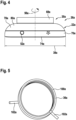
- the portable control element 22a forms a macro control element 26a (cf. also 4 ).
- the macro control element 26a has a maximum edge length 38a of a longest edge of the smallest imaginary cuboid, which just completely encloses the macro control element 26a.
- the portable control element 22a has a maximum edge length 38a of a longest edge of the smallest imaginary cuboid, which just completely encloses the macro control element 26a (cf. 2 ).
- the maximum edge lengths 38a of the macro control element 26a and of the portable control element 22a are identical.
- the maximum edge length 38a is 7 cm.
- the macro control element 26a has an infrared interface 52a.
- the portable operating element 22a has an infrared interface 52a.
- the macro control element 26a has four pushbuttons 48a.
- the portable operating element 22a has four pushbuttons 48a.
- the pushbuttons 48a can be actuated by moving the display holder 72a.
- the macro control element 26a forms a rotary, toggle and/or pressure switch.
- the macro control element 26a has two parts 30a, 32a that can move relative to one another (cf. 3 ).
- the parts 30a, 32a of the macro-control element 26a, which are mounted so that they can move in relation to one another, are mounted such that they can be tilted relative to an initial state in the coupled state.
- the parts 30a, 32a of the macro-control element 26a, which are mounted such that they can move in relation to one another, are mounted such that they can rotate about an axis 56a in the coupled state relative to an initial state.
- the axis 56a runs perpendicularly to the surface 66a of the coupling element 44a of the stationary element 20a (cf. 4 ).
- the axis 56a is perpendicular to a surface 76a of the display 28a.
- the mutually movably mounted parts 30a, 32a of the macro-control element 26a are mounted in the coupled state relative to an initial state along the axis 56a in a translationally displaceable manner.
- FIG. 3 shows a schematic, perspective interior view of the portable operating element 22a.
- the sub-housings 80a, 82a are plugged together to form the housing 78a.
- the housing 78a has a bowl shape inside.
- the housing 78a has a continuous recess 88a.
- the recess 88a is formed in a circular shape.
- the recess 88a is provided for receiving an insert element 84a.
- the insert element 84a is designed as an injection molded part that is separate from the housing 78a.
- the insert element 84a has latching hooks 86a.
- the latching hooks 86a are provided for a form-fitting assembly of the insert element 84a in the recess 88a of the housing 78a.
- the insert member 84a is secured within the housing 78a.
- the latching hooks 86a are provided to allow rotation of the insert element 84a in the recess 88a of the housing 78a.
- the latching hooks 86a have a minimized contact surface on one side surface, in particular not shown in detail, for contact with a side wall of the recess 88a when the housing 78a rotates. As a result, wear can advantageously be kept low.
- the latching hooks 86a are provided to allow movement of the insert element 84a in the recess 88a of the housing 78a in the direction of an interior of the housing 78a.
- the housing 78a and the insert element 84a form movably mounted parts 30a, 32a of the macro-control element 26a.
- An operating procedure of the macro operating element 26a includes an at least partial rotation of a Part 30a of the macro control element 26a compared to another part 32a of the macro control element 26a.
- An operating process of the macro-control element 26a includes an at least partial rotation of the housing 78a relative to the insert element 84a.
- the portable operating element 22a has a resistance element 34a.
- the resistance element 34a is provided for influencing and/or limiting the rotation of a part 30a of the macro-control element 26a relative to a further part 32a of the macro-control element 26a.
- the resistance element 34a is provided to limit the rotation of the housing 78a relative to the insert element 84a.
- the resistance element 34a is formed in one piece with the insert element 84a.
- the resistance element 34a is designed as an elevation 90a of the insert element 84a. In a mounted state, the elevation 90a extends into an interior of the housing 78a.
- the resistance element 34a has stop surfaces 96a on two opposite sides.
- the portable operating element 22a has two corresponding resistance elements 92a.
- the corresponding resistance elements 92a are formed in one piece with the housing 78a.
- the corresponding resistance elements 92a are designed as extensions projecting into the recess 88a.
- the corresponding resistance elements 92a have a corresponding stop surface 94a.
- the corresponding resistance elements 92a are arranged in two possible directions of rotation relative to the resistance element 34a.
- the corresponding resistance elements 92a are intended to strike the resistance element 34a when the macro-control element 26a rotates.
- one of the corresponding stop surfaces 94a makes contact with one of the stop surfaces 96a to limit the rotation of the macro-control element 26a.
- a maximum angle of rotation when part 32a of macro-control element 26a rotates relative to further part 32a of macro-control element 26a is approximately 12°, preferably approximately 11°.
- a rotation of the part 32a of the macro control element 26a relative to the further part 32a of the macro control element 26a by the maximum rotation angle is designed in such a way that it is not perceived by an operator as a rotation.
- other maximum rotation angles are also conceivable, which at least can sometimes be clearly perceived as a rotation by an operator.
- the macro control element 26a has a reset element 36a (cf. also figure 5 ).
- the restoring element 36a is provided for restoring at least one part 30a of the macro-operating element 26a that has been deflected from an initial state back to the initial state.
- the restoring element 36a is provided for a return deflection of the housing 78a after a deflection relative to the insert element 84a.
- the restoring element 36a is designed as a torsion spring 100a.
- the restoring element 36a has two tensioning elements 102a.
- the clamping elements 102a are designed as legs of the leg spring 100a.
- the clamping elements 102a are provided for applying a clamping force. The clamping force is greater the more the clamping elements 102a are moved towards one another.
- the reset element 36a is arranged in a recess 98a of the insert element 84a.
- the restoring element 36a is arranged at least essentially centered around the axis 56a.
- the restoring element 36a is arranged at least substantially centered in the recess 88a.
- the insert element 84a has two clamping elements 104a.
- the restoring element 36a is clamped between the two clamping elements 104a.
- the clamping elements 104a have contact surfaces 108a for the clamping elements 102a.
- the clamping elements 102a rest against the contact surfaces 108a of the clamping elements 104a under tension.
- the housing 78a has another clamping element 106a.
- the further clamping element 106a is designed as a groove.
- the further clamping element 106a extends over a circle segment running along an edge of the circular recess 88a.
- the further clamping element 106a is further spaced radially from a center of the recess 88a than the clamping element 104a.
- the contact surfaces 108a of the clamping elements 104a are in an initial state and/or basic state flush with side walls (not shown) of the further clamping element 106a lying in the circumferential direction of the recess 88a and extending in the radial direction of the recess 88a.
- a rotation of the housing 78a causes a displacement of the further clamping element 106a along a circular path.
- the clamping element 102a lying against a side wall of the further clamping element 106a moves with the further clamping element 106a when the housing 78a rotates.
- a moving of the clamping element 102a with the further clamping element 106a when the housing 78a rotates leads to a tensioning of the restoring element 36a.
- a relaxation of the restoring element 36a leads to an opposite rotation of the housing 78a.
- the opposite rotation of the housing 78a stops when the clamping element 102a strikes the contact surface 108a of the clamping element 102a.
- the macro control element 26a has a rotational position detection module 50a (cf. 1 ).
- the rotational position detection module 50a is provided for detecting a rotational position of a part 30a, 32a of the macro-operating element 26a.
- FIG. 6 shows a flowchart of a method for operating a wireless smart home operating device.
- the portable operating element 22a is coupled to the stationary element 20a by means of the coupling unit 24a.
- a macro control element 26a is formed by coupling the portable control element 22a and the stationary element 20a.
- the portable operating element 22a is used to carry out an operating process, in particular a setting and/or adjustment process for setting and/or adjusting at least one setting parameter of a smart home functional unit 10a, at least in part relative to the stationary element 20a rotates about an axis 56a, at least part of a volt revolution about the axis 56a.
- a part 30a of the portable operating element 22a is deflected back into an initial state after a deflection by means of the restoring element 36a.
- FIG. 7 shows part of an alternative coupling unit 24b of a wireless smart home operating device.
- the coupling unit 24b has coupling elements 40b, 44b.
- This in 7 shown alternative coupling element 40b of a portable control element 22b of a wireless smart home control device has an alternative form.
- Alternatively can 7 also show an alternative form of a coupling element 44b of a stationary element 20b of the wireless smart home operating device.
- the shape of the coupling element 40b, 44b is asymmetrical.
- the shape of the coupling element 40b, 44b is rotationally asymmetrical.
- the coupling element 40b, 44b is designed as part of a poka-yoke system. As a result, incorrect operation, in particular incorrect coupling, can advantageously be avoided.
- the coupling unit 24b has an additional coupling element 118b.
- the additional coupling element 118b is designed as a circular recess and/or a columnar elevation.
- the additional coupling element 118b forms another part of the poka-yoke system.
- the additional coupling element 118b advantageously forms an additional safeguard against misuse and/or unauthorized use.
Landscapes
- Engineering & Computer Science (AREA)
- General Engineering & Computer Science (AREA)
- Mechanical Engineering (AREA)
- Computer Networks & Wireless Communication (AREA)
- Physics & Mathematics (AREA)
- General Physics & Mathematics (AREA)
- Selective Calling Equipment (AREA)
Description
- Es ist bereits eine drahtlose Smarthome-Bedienvorrichtung mit zumindest einem stationären Element, mit zumindest einem tragbaren Bedienelement und mit zumindest einer Koppeleinheit zu einer Kopplung des stationären Elements mit dem tragbaren Bedienelement, vorgeschlagen worden.
-
US 2017/059196 A1 offenbart die Merkmale des Oberbegriffs des Anspruchs 1: eine drahtlose Smarthome-Bedienvorrichtung (102), zumindest zu einer Bedienung einer SmarthomeFunktionseinheit (vgl. Abs. [0048], [0051] und [0053]), mit zumindest einem stationären Element (542), mit zumindest einem tragbaren Bedienelement (540) und mit zumindest einer Koppeleinheit zu einer physischen Kopplung des stationären Elements (542) mit dem tragbaren Bedienelement (540) (vgl. Abs. [0073]). Das tragbare Bedienelement (540) bildet in einem mittels der Koppeleinheit gekoppelten Zustand ein Makrobedienelement aus, wobei das Makrobedienelement zumindest ein Rotationserkennungsmodul aufweist, zumindest zu einer Erkennung einer Rotationsposition, zumindest eines Teils (512, 514) des Makrobedienelements (vgl. Abs. [0004], [0041], [0071], [0075] und [0078]), und wobei ein Bedienvorgang des Makrobedienelements zumindest teilweise ein zumindest teilweises Rotieren zumindest eines Teils (512) des Makrobedienelements gegenüber zumindest einem weiteren Teil (514) des Makrobedienelements umfasst (vgl. Abs. [0002] sowie Figur 5A). - Offenbarung der Erfindung Erfindungsgemäss werden eine Smarthome-Bedienvorrichtung gemäss Anspruch 1 und ein Verfahren gemäss Anspruch 13 bereitgestellt. Bevorzugte Ausführungsformen sind in den abhängigen Ansprüchen definiert.
- Die Erfindung geht aus von einer drahtlosen Smarthome-Bedienvorrichtung, insbesondere zumindest zu einer Bedienung zumindest einer Leuchte, einer Alarmanlage, eines Thermostaten, einer schaltbaren Steckdose oder ähnlichem, mit zumindest einem stationären Element, mit zumindest einem tragbaren Bedienelement und mit zumindest einer Koppeleinheit zu einer, insbesondere physischen, Kopplung des stationären Elements mit dem tragbaren Bedienelement.
- Es wird vorgeschlagen, dass das tragbare Bedienelement in einem mittels der Koppeleinheit gekoppelten Zustand ein, insbesondere genau ein, Makrobedienelement ausbildet. Dadurch können insbesondere vorteilhafte Eigenschaften hinsichtlich eines Bedienkomforts erreicht werden, insbesondere indem eine einfache und/oder intuitive Bedienmöglichkeit geschaffen werden kann. Zudem kann vorteilhaft mittels des Makrobedienelements ein körperliches Feedback als Reaktion auf eine Bedienung erzeugt werden, wodurch insbesondere eine hohe Bedienermotivation erreicht werden kann. Außerdem kann dadurch vorteilhaft eine gute Merkbarkeit, beispielsweise eines mittels der Smarthome-Bedienvorrichtung eingegebenen Codes, erreicht werden. Ferner kann vorteilhaft eine Flexibilität erhöht werden, beispielsweise indem das tragbare Element mit verschiedenen stationären Elementen an verschiedenen Orten koppelbar ist und/oder indem vorteilhaft eine Mehrzahl an verschiedenen Smarthome Funktionseinheiten mittels des Makrobedienelements bedienbar sein können. Beispielsweise könnten verschiedene Smarthome-Funktionseinheiten verschiedenen stationären Elementen zugeordnet sein, mit welchen die tragbare Einheit koppelbar ist. Alternativ könnten verschiedene Smarthome-Funktionseinheiten auf dem tragbaren Element auswählbar sein, wobei insbesondere eine Kopplung mit dem stationären Element eine Bedienung der ausgewählten Smarthome-Funktionseinheit ermöglicht.
- Insbesondere ist das Makrobedienelement dazu vorgesehen, einen Einstell- und/oder Bedienvorgang mittels Nudging zu ermöglichen, wobei insbesondere ein Einstell- und/oder Bedienvorgang mittels eines leichten Anstoßens, leichten Verkippens und/oder leichten Verdrehens zumindest eines Teils des Makrobedienelements vornehmbar ist. Vorzugsweise erfolgt nach jedem Einstell- und/oder Bedienvorgang mittels Nudging, insbesondere mittels eines leichten Anstoßens, Verkippens und/oder Verdrehens des Makrobedienelements eine selbsttätige Rückauslenkung, welche vorteilhaft als ein körperliches Feedback für eine erfolgreiche Durchführung des Einstell- und/oder Bedienvorgangs von einem Bediener wahrnehmbar ist.
- Unter "drahtlos" soll insbesondere frei von Kabeln, insbesondere elektrischen Leitern und/oder Lichtwellenleitern, kommunizierend verstanden werden. Insbesondere kommuniziert eine drahtlose Smarthome-Bedienvorrichtung mittels einem Funkverfahren, beispielsweise Bluetooth, WLAN, ZigBee, NFC, Wibree und/oder WiMAX und/oder einem optischen Datenübertragungsverfahren, wie beispielsweise einem Infrarot-Datenübertragungsverfahren. Unter einer "Bedienung einer Smarthome-Funktionseinheit" soll insbesondere eine Aktivierung und/oder Deaktivierung der Smarthome-Funktionseinheit und/oder zumindest einer Funktion der Smarthome-Funktionseinheit, eine Einstellung zumindest eines Funktionsparameters der Smarthome-Funktionseinheit und/oder eine Abfrage zumindest eines Funktionsparameters der Smarthome-Funktionseinheit verstanden werden. Eine Smarthome-Funktionseinheit kann insbesondere als zumindest eine Alarmanlage, als zumindest eine Beleuchtungsanlage, insbesondere zumindest eine Leuchte, als zumindest eine Heizungsanlage, als zumindest eine Klimatisierungsanlage, als zumindest ein Sicht- und/oder Sonnenschutz, als zumindest eine schaltbare Steckdose, als zumindest ein Haushaltsgerät und/oder als zumindest ein Unterhaltungselektronikgerät ausgebildet sein. Das stationäre Element ist insbesondere als ein Element ausgebildet, welches, insbesondere in einem statischen Bauwerk, beispielsweise einer Hauswand, unbeweglich verankerbar ist. Das tragbare Bedienelement ist insbesondere als ein elektronisches, vorzugsweise batterie- und/oder akkubetriebenes, Bedienelement ausgebildet. Das tragbare Bedienelement ist insbesondere von einer erwachsenen Durchschnittsperson in einer Hand tragbar. Insbesondere ist das tragbare Bedienelement leichter als 2 kg, vorzugsweise leichter als 1 kg, vorteilhaft leichter als 500 g, besonders vorteilhaft leichter als 300 g, bevorzugt leichter als 150 g und besonders bevorzugt leichter als 100 g. Unter einer "physischen Kopplung" soll insbesondere eine Kopplung verstanden werden, bei der sich die miteinander koppelbaren Elemente in einem gekoppelten Zustand kontaktieren. Insbesondere bewirkt die physische Kopplung zu einer Haltekraft zwischen miteinander koppelbaren Elemente in einem gekoppelten Zustand. Insbesondere ist die physische Kopplung verschieden von einer reinen Datenverbindung, insbesondere einer drahtlosen Datenverbindung und/oder einer Datenverbindung mittels eines Kabels. Unter einem "Makrobedienelement" soll insbesondere ein Bedienelement verstanden werden, welches eine Angriffsfläche und/oder Bedienfläche von zumindest 200 cm2, vorzugsweise zumindest 150 cm2, vorteilhaft zumindest 100 cm2, besonders vorteilhaft zumindest 70 cm2, bevorzugt zumindest 50 cm2 und besonders bevorzugt zumindest 35 cm2 aufweist. Insbesondere ist das Makrobedienelement verschieden von einer Tastatur ausgebildet. Insbesondere ist das Makrobedienelement zu einer Bedienung mit zumindest einer ganzen Hand, vorzugsweise zumindest einer Handinnenfläche vorgesehen. Insbesondere ist die drahtlose Smarthome-Bedienvorrichtung im gekoppelten Zustand frei von weiteren Makrobedienelementen.
- Ferner wird vorgeschlagen, dass das Makrobedienelement zumindest einen Dreh- Kipp- und/oder Druckschalter ausbildet. Dadurch können insbesondere vorteilhafte Eigenschaften hinsichtlich eines Bedienkomforts erreicht werden, insbesondere indem eine einfache und/oder intuitive Bedienmöglichkeit geschaffen werden kann. Zudem kann vorteilhaft mittels des Makrobedienelements ein körperliches Feedback als Reaktion auf eine Bedienung erzeugt werden, wodurch insbesondere eine hohe Bedienermotivation erreicht werden kann. Außerdem kann dadurch vorteilhaft eine gute Merkbarkeit, beispielsweise eines mittels der Smarthome-Bedienvorrichtung eingegebenen Codes, erreicht werden.
- Des Weiteren wird vorgeschlagen, dass das tragbare Bedienelement, insbesondere das Makrobedienelement, zumindest ein, insbesondere in das tragbare Bedienelement, vorzugsweise in das Makrobedienelement, integrierten, Display aufweist. Dadurch können insbesondere vorteilhafte Eigenschaften hinsichtlich eines Bedienkomforts erreicht werden. Insbesondere können vorteilhaft mittels des tragbaren Bedienelements, insbesondere des Makrobedienelements vornehmbare und/oder vorgenommene Einstellungen direkt anzeigbar sein. Das Display kann insbesondere als zumindest ein LCD-Display, als zumindest ein OLED-Display und/oder als zumindest ein SED-Display ausgebildet sein. Insbesondere weist das Display eine Hintergrundbeleuchtung, vorzugsweise ein LED-Backlight, auf. Vorzugsweise ist das Display als ein E-Paper-Display ausgebildet. Dadurch kann vorteilhaft ein niedriger Energieverbrauch ermöglicht werden. Vorzugsweise ist das Display auf einer im gekoppelten Zustand einem Benutzer zugewandten Seite und/oder einer dem stationären Element abgewandten Seite angeordnet. Alternativ oder zusätzlich ist vorstellbar, dass das tragbare Element einen Projektor zu einer Projektion einer Anzeige, beispielsweise auf eine das tragbare Element umgebende Wand und/oder eine Hand eines Benutzers aufweist. Zudem ist denkbar, dass das tragbare Element zumindest eine Leuchteinheit und/oder eine akustische Signaleinheit aufweist zu einer Bestätigung eines Bedienvorgangs durch einen Benutzer. Beispielsweise könnte nach jeder Betätigung des, insbesondere als Dreh- Kipp- und/oder Druckschalter ausgebildeten, Makrobedienelements ein Teil des Makrobedienelements und/oder der das Makrobedienelement benutzenden Hand kurzzeitig durch die Leuchteinheit angeleuchtet werden.
- Zudem wird vorgeschlagen, dass eine maximale Kantenlänge einer längsten Kante eines kleinsten gedachten Quaders, welcher das Makrobedienelement gerade noch vollständig umschließt weniger als 10 cm, insbesondere weniger als 8,5 cm, vorzugsweise weniger als 7 cm, vorteilhaft weniger als 5,5 cm und bevorzugt mehr als 4 cm beträgt. Dadurch können insbesondere vorteilhafte Eigenschaften hinsichtlich eines Bedienkomforts erreicht werden, insbesondere kann eine gute Haptik ermöglicht werden. Vorteilhaft kann dadurch eine Größe des Makrobedienelements auf durchschnittliche Größen von Handinnenflächen einer Benutzergruppe abgestimmt werden. Insbesondere beträgt eine maximale Kantenlänge einer zweitlängsten Kante eines kleinsten gedachten Quaders, welcher das Makrobedienelement gerade noch vollständig umschließt weniger als 10 cm, insbesondere weniger als 8,5 cm, vorzugsweise weniger als 7 cm, vorteilhaft weniger als 5,5 cm und bevorzugt mehr als 4 cm.
- Außerdem wird vorgeschlagen, dass das stationäre Element frei ist von beweglichen, insbesondere rotierbaren, Teilen. Dadurch kann vorteilhaft eine geringe Komplexität erreicht werden, wodurch vorteilhaft Kosten reduziert werden können. Insbesondere ist das stationäre Element zu einer Befestigung an einem festen Gebäudeteil, beispielsweise einer Wand, vorgesehen. Es ist denkbar, dass stationäre Elemente an verschiedenen Orten eines Smarthomes installiert sind. Dadurch können vorteilhaft mittels des tragbaren Bedienelements an verschiedenen Orten Makrobedienelemente erzeugt werden, welche insbesondere zu einer Bedienung identischer und/oder verschiedener Smarthome-Funktionselemente verwendbar sind. Dadurch kann vorteilhaft ein Benutzerkomfort weiter verbessert werden.
- Erfindungsgemäss wird vorgeschlagen, dass ein Bedienvorgang, insbesondere ein Einstell- und/oder Verstellvorgang, des Makrobedienelements zumindest teilweise ein zumindest teilweises Rotieren zumindest eines Teils des Makrobedienelements, insbesondere des tragbaren Bedienelements, gegenüber zumindest einem weiteren Teil des Makrobedienelements, insbesondere des tragbaren Bedienelements, umfasst. Dadurch können insbesondere vorteilhafte Eigenschaften hinsichtlich eines Bedienkomforts erreicht werden, insbesondere indem eine einfache und/oder intuitive Bedienmöglichkeit geschaffen werden kann. Zudem kann vorteilhaft mittels des Makrobedienelements ein körperliches Feedback als Reaktion auf eine Bedienung erzeugt werden, wodurch insbesondere eine hohe Bedienermotivation erreicht werden kann. Außerdem kann dadurch vorteilhaft eine gute Merkbarkeit, beispielsweise eines mittels der Smarthome-Bedienvorrichtung eingegebenen Codes, erreicht werden.
- Erfindungsgemäss sind der Teil des Makrobedienelements, insbesondere des tragbaren Bedienelements, und/oder der weitere Teil des Makrobedienelements, insbesondere des tragbaren Bedienelements insbesondere gegeneinander, rotierbar gelagert. Eine rotierbare Lagerung des Teils des Makrobedienelements, insbesondere des tragbaren Bedienelements, und/ oder des weiteren Teils des Makrobedienelements, insbesondere des tragbaren Bedienelements, ermöglicht und/oder erlaubt insbesondere eine Rotation zumindest des Teils des Makrobedienelements, insbesondere des tragbaren Bedienelements, und/oder zumindest des weiteren Teils des Makrobedienelements, insbesondere des tragbaren Bedienelements, in einem Uhrzeigersinn und/oder eine Rotation entgegen dem Uhrzeigersinn, insbesondere relativ zu dem jeweiligen anderen Teil des Makrobedienelements, insbesondere des tragbaren Bedienelements. Insbesondere ermöglicht und/oder erlaubt eine rotierbare Lagerung des Teils des Makrobedienelements, insbesondere des tragbaren Bedienelements, und/ oder des weiteren Teils des Makrobedienelements, insbesondere des tragbaren Bedienelements, eine, vorzugsweise gegenseitige, Rotation zumindest des Teils des Makrobedienelements, insbesondere des tragbaren Bedienelements, und/oder zumindest des weiteren Teils des Makrobedienelements, insbesondere des tragbaren Bedienelements, um einen Winkel von zumindest 5°, vorzugsweise zumindest 8°, vorteilhaft zumindest 10°, besonders vorteilhaft zumindest 12° . Unter einer "gegenseitigen Rotation" soll insbesondere eine Rotation verstanden werden, welche ein Verdrehen des Teils des Makrobedienelements, insbesondere des tragbaren Bedienelements, gegenüber dem weiteren Teil des Makrobedienelements, insbesondere des tragbaren Bedienelements, umfasst.
- Ferner wird vorgeschlagen, dass das tragbare Bedienelement zumindest ein Widerstandselement zu einer, insbesondere periodischen, Beeinflussung und/oder zu einer Begrenzung einer Rotation zumindest eines, insbesondere rotierbaren, Teils des Makrobedienelements, insbesondere des tragbaren Bedienelements, gegenüber zumindest einem weiteren Teil des Makrobedienelements, insbesondere des tragbaren Bedienelements, aufweist. Dadurch können insbesondere vorteilhafte Eigenschaften hinsichtlich eines Bedienkomforts erreicht werden, insbesondere indem eine einfache und/oder intuitive Bedienmöglichkeit geschaffen werden kann. Zudem kann vorteilhaft mittels des Makrobedienelements ein körperliches Feedback als Reaktion auf eine Bedienung erzeugt werden, wodurch insbesondere eine hohe Bedienermotivation erreicht werden kann.
- Zudem kann vorteilhaft eine gute Steuerbarkeit und/oder Einstellpräzision bei einem Bedienvorgang ermöglicht werden, insbesondere indem der Bediener durch Fühlen eines Widerstands abschätzen kann, wie weit er das Makrobedienelement bewegt hat und/oder ob er das Makrobedienelement weit genug für die gewünschte Einstellung bewegt hat. Zudem kann vorteilhaft eine einfache Eingabe eines Codes, welcher beispielsweise aus einer Abfolge von kurzen Rechts- und/ oder Linksdrehungen besteht, ermöglicht werden. Insbesondere ist das Widerstandselement dazu vorgesehen, eine Rotation des zumindest einen Teils des Makrobedienelements, insbesondere des tragbaren Bedienelements, gegenüber des zumindest einen weiteren Teils des Makrobedienelements, insbesondere des tragbaren Bedienelements auf einen maximalen Rotationswinkel von höchstens 15°, bevorzugt von höchstens 12° und besonders bevorzugt von höchstens 8° zu begrenzen. Alternativ oder zusätzlich ist das Widerstandselement dazu vorgesehen, einen, insbesondere durch einen Bediener bei einem Verdrehen des Makrobedienelements fühlbaren, Widerstand gegen die Rotationsbewegung jeweils bei, insbesondere zumindest im Wesentlichen gleich beabstandeten, Rotationsschritten von zumindest 2°, vorzugsweise zumindest 3°, vorteilhaft zumindest 5°, bevorzugt zumindest 10° und besonders bevorzugt höchstens 20° zu erzeugen. Das Widerstandselement kann insbesondere als ein Festanschlag oder als ein Reibelement, welches insbesondere dazu vorgesehen ist, bei bestimmten Rotationsschritten einen erhöhten, vorzugsweise eine Freiheit der Rotation beeinflussenden, Reibungswiderstand zu erzeugen, ausgebildet sein. Unter einer "Beeinflussung der Rotation" soll insbesondere eine Beeinflussung der Rotationsfreiheit der Rotation, insbesondere durch eine Veränderung, insbesondere Erhöhung, eines Rotationswiderstands, verstanden werden. Unter einer "Begrenzung der Rotation" soll insbesondere eine Beschränkung des Rotationswinkels auf den maximalen Rotationswinkel verstanden werden.
- Zudem wird vorgeschlagen, dass ein maximaler Rotationswinkel bei einem Rotieren zumindest eines Teils des Makrobedienelements gegenüber zumindest einem weiteren Teil des Makrobedienelements höchstens 15°, vorteilhaft höchstens 12° und besonders vorteilhaft zumindest 5° beträgt. Dadurch kann vorteilhaft eine einfache und intuitive Bedienmöglichkeit geschaffen werden. Vorzugsweise beträgt ein Rotationswinkel bei einem einmaligen Betätigen des Makrobedienelements mittels Rotation etwa 11°, insbesondere zumindest 10° und höchstens 12°. Vorzugsweise beträgt ein Rotationswinkel bei einem einmaligen Betätigen des Makrobedienelements mittels Rotation höchstens etwa 11°, insbesondere höchstens zwischen 10° und 12°. Dadurch kann vorteilhaft eine für einen Bediener als angenehm empfundene Bedienbarkeit erreicht werden. Vorteilhaft kann eine Betätigung des Makrobedienelements mittels Rotation um etwa 11°, insbesondere um zumindest 10° und um höchstens 12°, von einem Bediener gut als eine Bewegung wahrgenommen werden, wobei die Rotation um etwa 11°, insbesondere um zumindest 10° und um höchstens 12°, von dem Bediener vorteilhaft nicht als eine Drehung wahrgenommen wird. Insbesondere übersteigt eine Bewegung des Makrobedienelements um etwa 11°, insbesondere um zumindest 10° und um höchstens 12°, knapp eine Wahrnehmbarkeitsgrenze, welche die durch den Bediener vorgenommene Bewegung vorteilhaft von einer, insbesondere produktionsbedingten und/oder qualitätsabhängigen, Bewegung des Makrobedienelements durch ein Wackeln und/oder ein Spiel abhebt. Vorteilhaft kann dem Bediener dadurch eine schnelle und/oder zeitsparende Bedienbarkeit ermöglicht werden, beispielsweise kann dadurch ein schnelles Durchgehen und/oder Bedienen eines auf dem Display angezeigten Menüs ermöglicht werden, wodurch insbesondere ein Bedienkomfort verbessert werden kann. Vorzugsweise ist der maximale Rotationswinkel bei einer Drehung in Uhrzeigerrichtung gleich wie bei einer Drehung in die entgegengesetzte Richtung.
- Erfindungsgemäss wird vorgeschlagen, dass das Makrobedienelement, insbesondere das tragbare Bedienelement, zumindest ein Rückstellelement aufweist zu einer Rückstellung, insbesondere einer rotatorischen und/oder translatorischen Auslenkung, zumindest eines aus einem Ausgangzustand ausgelenkten Teils des Makrobedienelements, insbesondere des tragbaren Bedienelements, zurück in den Ausgangszustand. Dadurch können insbesondere vorteilhafte Eigenschaften hinsichtlich eines Bedienkomforts erreicht werden, insbesondere indem eine einfache und/oder intuitive Bedienmöglichkeit geschaffen werden kann. Zudem kann insbesondere durch eine Bedienerführung mittels einer selbstständigen Rückauslenkung vorteilhaft eine Simplizität einer Bedienfunktion erhöht werden. Des Weiteren können vorteilhaft Fehlbedienungen, beispielswiese durch eine fehlerhafte und/oder unzureichende Rückauslenkung durch einen Bediener, vermieden werden. Das Rückstellelement kann insbesondere zumindest teilweise als zumindest eine Feder, vorzugsweise eine Schenkelfeder, als zumindest ein elastisches Band, beispielsweise ein Gummiband, als zumindest ein elastischer Block, beispielsweise ein Gummiblock und/oder als zumindest ein Elektromotor ausgebildet sein. Unter einem "Ausgangszustand" soll insbesondere ein zumindest im Wesentlichen von äußeren, insbesondere durch einen Bediener erzeugten, Kräften freier Zustand verstanden werden. Der Ausgangszustand des Makrobedienelements ist insbesondere als der Zustand ausgebildet, in welchem sich das Makrobedienelement unmittelbar nach einer Kopplung des tragbaren Bedienelements und des stationären Elements befindet
- Des Weiteren wird vorgeschlagen, dass die Koppeleinheit zumindest ein Koppelelement, insbesondere Formschlusselement, aufweist, zu einer Ausbildung einer zumindest im Wesentlichen passgenauen, insbesondere formschlüssigen, Verbindung zumindest des stationären Elements mit zumindest dem tragbaren Bedienelement. Dadurch kann vorteilhaft eine stabile Kopplung ermöglicht werden. Zudem kann vorteilhaft mittels eines Koppelelements eine bevorzugte relative Ausrichtung des tragbaren Bedienelements und des stationären Elements zueinander festgelegt werden. Das Koppelelement kann insbesondere als ein Formschlusselement ausgebildet sein, welches insbesondere zusätzlich zu einer passgenauen Verbindung eine Haltekraft erzeugende Verbindung ausbildet. Insbesondere umfasst die Koppeleinheit ein Koppelelement des tragbaren Bedienelements und/oder ein Koppelelement des stationären Elements. Das Koppelelement des tragbaren Bedienelements und das Koppelelement des stationären Elements sind als miteinander, insbesondere passgenau, korrespondierende Koppelelemente ausgebildet. Insbesondere ist das tragbare Bedienelement mittels des Koppelelements des tragbaren Bedienelements auf das stationäre Element, insbesondere das Koppelelement des stationären Elements, aufsetzbar, insbesondere aufsteckbar. Insbesondere weisen die Koppelelemente zumindest eine zumindest im Wesentlichen zueinander komplementäre Außenkontur auf. Insbesondere ist die Außenkontur des Koppelelements des tragbaren Bedienelements und/oder des stationären Elements asymmetrisch und/oder rotationsunsymmetrisch ausgebildet. Dadurch kann vorteilhaft ein Verdrehen der Koppelelemente gegeneinander, insbesondere bei einer Rotation zumindest eines Teils des tragbaren Bedienelements, vermieden werden. Zudem ist denkbar, dass die Außenkontur eine, insbesondere komplexe, Form ausbildet, welche dazu vorgesehen ist, bevorzugt eine Passverbindung möglichst ausschließlich zwischen dem tragbaren Bedienelement und dem stationären Element zuzulassen, wodurch vorteilhaft eine Fehlbedienung unterbunden werden kann. Insbesondere sind die Koppelelemente als Komponenten eines Poka-Yoke-Systems ausgebildet, wodurch vorteilhaft eine Gefahr einer Fehlbedienung weiter reduziert werden kann. Insbesondere ist das Koppelelement des tragbaren Bedienelements als eine weibliche Steckverbindung, insbesondere Buchse, ausgebildet. Insbesondere ist das Koppelelement des stationären Elements als eine männliche Steckverbindung, insbesondere hervorstehendes Steckerelement, ausgebildet. Es ist denkbar, dass das tragbare Bedienelement und/oder das stationäre Element zumindest ein weiteres Koppelelement aufweist zu einer weiteren zumindest im Wesentlichen passgenauen, insbesondere formschlüssigen, Verbindung des stationären Elements mit zumindest dem tragbaren Bedienelement. Dadurch kann vorteilhaft eine besonders hohe Bediensicherheit erreicht werden, insbesondere indem Fehlbedienungen, beispielsweise durch eine fehlerhafte Kopplung und/oder durch eine Kopplung unzusammenpassender Teile, vermieden werden können. Unter einer "im Wesentlichen passgenauen Verbindung" soll insbesondere eine Verbindung von zumindest zwei Koppelelementen verstanden werden, bei welcher zumindest 90 %, vorzugsweise zumindest 95 %, vorteilhaft zumindest 98 %, bevorzugt zumindest 99 % und besonders bevorzugt 100 % einer Außenkontur eines Querschnitts eines Koppelelements eine Außenkontur eines Querschnitts des anderen Koppelelements berühren. Vorzugsweise ist eine passgenaue Verbindung spielfrei.
- Weiterhin wird vorgeschlagen, dass die Koppeleinheit, insbesondere das stationäre Element, zumindest ein Magnetelement aufweist, zu einer Ausbildung einer kraftschlüssigen Verbindung zumindest mit dem tragbaren Bedienelement. Dadurch kann vorteilhaft ein Bedienkomfort erhöht werden, insbesondere indem eine sicher und einfach verbindbare und/oder lösbare Koppelmöglichkeit geschaffen werden kann. Zudem kann vorteilhaft eine Kopplung vereinfacht werden, insbesondere indem mittels der Magnetelemente eine Feinausrichtung der zu koppelnden Elemente unterstützt werden kann. Insbesondere ist das Magnetelement als ein Permanentmagnet ausgebildet. Alternativ oder zusätzlich kann das Magnetelement als ein Elektromagnet ausgebildet sein. Insbesondere weist die Koppeleinheit, vorzugsweise das stationäre Element, eine Mehrzahl an Magnetelementen auf. Insbesondere weist die Koppeleinheit, insbesondere das tragbare Bedienelement, zumindest ein, vorzugsweise eine Mehrzahl an, Metallelementen auf. Das Metallelement ist insbesondere zumindest teilweise aus einem magnetischen, vorzugsweise ferromagnetischen, Material ausgebildet. Das Metallelement ist insbesondere zu einer Wechselwirkung mit dem Magnetelement vorgesehen. Vorzugsweise ist das tragbare Bedienelement frei von Magnetelementen, insbesondere Permanentmagneten.
- Wenn die Koppeleinheit ein Erkennungsmodul zu einer gegenseitigen Identifikation des stationären Elements und des tragbaren Bedienelements aufweist, kann vorteilhaft eine Fehlfunktion und/oder Fehlbedienung vermieden werden. Zudem kann vorteilhaft eine Sicherheit erhöht werden, beispielsweise indem bestimmte tragbare Bedienelemente für eine Kopplung mit bestimmten stationären Elementen freischaltbar und/oder sperrbar sind, dadurch kann beispielsweise eine unautorisierte Bedienung einer Smarthome-Funktion, beispielsweise eine Alarmanlagenaktivierung und/oder -deaktivierung, unterbunden werden. Das Erkennungsmodul kann insbesondere als ein mechanisches Erkennungsmodul, beispielweise ein Schlüssel und/oder eine bestimmte Form der Koppelelemente, insbesondere Formschlusselemente, und/oder als ein elektronisches Erkennungsmodul, welches beispielsweise über Magnetfelder und/oder elektrische Felder eine Identifikation durchführt, ausgebildet sein. Insbesondere erfolgt eine Erkennung mittels des Erkennungsmoduls automatisch. Insbesondere kann das Erkennungsmodul zumindest teilweise als Teil des stationären Elements und/oder als Teil des tragbaren Bedienelements ausgebildet sein. Insbesondere kann eine Identifikationsfunktion des Erkennungsmoduls konfigurierbar sein, beispielsweise indem zulässige Kopplungen definierbar sind.
- Zudem wird vorgeschlagen, dass das Makrobedienelement, insbesondere das tragbare Bedienelement, zumindest einen Drucktaster aufweist. Dadurch kann vorteilhaft eine Flexibilität erhöht werden, insbesondere indem zusätzliche Bedienmöglichkeiten geschaffen werden können. Insbesondere kann der Drucktaster, welcher insbesondere verschieden von einem Ein- / Aus-Schalter ausgebildet ist, an einem Seitenbereich des tragbaren Bedienelements und/oder auf einer Vorderseite, welche insbesondere das Display umfasst, des tragbaren Bedienelements angeordnet sein. Alternativ oder zusätzlich ist vorstellbar, dass das gesamte Makrobedienelement einen Drucktaster ausbildet.
- Erfindungsgemäss wird vorgeschlagen, dass das Makrobedienelement, insbesondere das tragbare Bedienelement, zumindest ein Rotationspositionserkennungsmodul aufweist, zumindest zu einer Erkennung einer Rotationsposition, zumindest eines, insbesondere rotierbaren, Teils des Makrobedienelements, insbesondere das tragbare Bedienelements. Dadurch kann vorteilhaft eine Flexibilität erhöht werden, insbesondere indem zusätzliche Bedienmöglichkeiten geschaffen werden können. Insbesondere ist das Rotationspositionserkennungsmodul dazu vorgesehen, ein "rotiertes Halten" bei einer bestimmten Winkelposition, insbesondere für einen, einen bestimmten Schwellenwert überschreitenden Zeitraum, zu sensieren. Dadurch kann vorteilhaft eine zusätzliche Bedienfunktion eines "rotiertes Haltens" des Makrobedienelements für einen bestimmten Zeitraum geschaffen werden. Insbesondere ist das Rotationspositionserkennungsmodul als eine optische Messvorrichtung ausgebildet. Alternativ kann das Rotationspositionserkennungsmodul als ein Tastmodul, beispielsweise ein Laufrad, als eine elektrische Messvorrichtung, welche beispielweise je nach Rotationsposition eine Spannung an einem unterschiedlichen Ort abgreift und/oder als ein Gyrosensor ausgebildet sein.
- Des Weiteren wird vorgeschlagen, dass das Makrobedienelement eine Infrarot Schnittstelle aufweist. Dadurch kann vorteilhaft eine hohe Flexibilität erreicht werden, insbesondere indem eine Steuermöglichkeit, insbesondere Fernsteuermöglichkeit für Smarthome-Funktionseinheiten mit zumindest einer Infrarot Schnittstelle, beispielsweise einem Fernseher, geschaffen werden kann. Vorteilhaft kann dadurch eine Remote-Remote-Funktion geschaffen werden. Beispielweise ist denkbar, dass das Makrobedienelement Informationen von einem Smartphone empfängt, beispielsweise eine Vormerkung eines bestimmten vom Benutzer präferierten Art eines Fernsehprogramms, woraufhin die Smarthome-Bedienvorrichtung für den Benutzer, wenn er einen Fernsehmodus mittels der drahtlosen Smarthome-Bedienvorrichtung aktiviert, automatisch einen Sender mit dem aktuell passendsten Programm über die Infrarot-Schnittstelle anwählt. Dadurch kann vorteilhaft ein Bedienkomfort verbessert werden.
- Weiterhin wird ein tragbares Bedienelement der drahtlosen Smarthome-Bedienvorrichtung mit einem Koppelelement vorgeschlagen. Dadurch können insbesondere vorteilhafte Eigenschaften hinsichtlich eines Bedienkomforts erreicht werden, insbesondere indem eine Bedienung verschiedener Smarthome-Funktionseinheiten mobil aus verschiedenen Orten innerhalb und/oder außerhalb eines Smarthomes ermöglicht werden kann. Zudem kann vorteilhaft das tragbare Bedienelement flexibel an verschiedenen Orten mit verschiedenen stationären Elementen zur Bedienung verschiedener Smarthome-Funktionseinheiten koppelbar sein.
- Zudem wird ein stationäres Element der drahtlosen Smarthome-Bedienvorrichtung mit einem, insbesondere mit einem Koppelelement der Koppeleinheit koppelbaren, vorzugsweise zu dem Koppelelement des tragbaren Bedienelements komplementären, Koppelelement vorgeschlagen. Dadurch können insbesondere vorteilhafte Eigenschaften hinsichtlich eines Bedienkomforts erreicht werden, insbesondere indem eine einfache und/oder intuitive Bedienmöglichkeit geschaffen werden kann.
- Außerdem wird ein System mit zumindest einer drahtlosen Smarthome-Bedienvorrichtung und mit zumindest einer Smarthome-Funktionseinheit vorgeschlagen. Dadurch können insbesondere vorteilhafte Eigenschaften hinsichtlich eines Bedienkomforts erreicht werden, insbesondere indem eine einfache und/oder intuitive Bedienmöglichkeit geschaffen werden kann. Zudem kann vorteilhaft mittels des Makrobedienelements ein körperliches Feedback als Reaktion auf eine Bedienung erzeugt werden, wodurch insbesondere eine hohe Bedienermotivation erreicht werden kann.
- Verfahren zur Bedienung einer drahtlosen Smarthome-Bedienvorrichtung mit zumindest einem stationären Element, mit zumindest einem tragbaren Bedienelement und mit zumindest einer Koppeleinheit zu einer, insbesondere physischen, Kopplung des stationären Elements mit dem tragbaren Bedienelement, wobei das tragbare Bedienelement mittels der Koppeleinheit mit dem stationären Element zur Ausbildung eines Makrobedienelements gekoppelt wird. Dadurch können insbesondere vorteilhafte Eigenschaften hinsichtlich eines Bedienkomforts erreicht werden, insbesondere indem ein einfach und/oder intuitiv zu bedienendes Bedienelement geschaffen werden kann.
- Weiterhin wird vorgeschlagen, dass, insbesondere in zumindest einem weiteren Verfahrensschritt, das tragbare Bedienelement zu einer Durchführung eines Bedienvorgangs, insbesondere eines Einstell- und/oder Verstellvorgangs zur Ein- und/oder Verstellung zumindest eines Einstellparameters einer Smarthome-Funktionseinheit, zumindest zu einem Teil relativ zu dem stationären Element um eine Achse, zumindest um einen Teil einer vollen Umdrehung um die Achse rotiert wird. Dadurch können insbesondere vorteilhafte Eigenschaften hinsichtlich eines Bedienkomforts erreicht werden, insbesondere indem eine einfache und/oder intuitive Bedienmöglichkeit geschaffen werden kann. Zudem kann vorteilhaft mittels des Makrobedienelements ein körperliches Feedback als Reaktion auf eine Bedienung erzeugt werden, wodurch insbesondere eine hohe Bedienermotivation erreicht werden kann.
- Die erfindungsgemäße drahtlose Smarthome-Bedienvorrichtung und/oder das erfindungsgemäße Verfahren soll/sollen hierbei nicht auf die oben beschriebene Anwendung und Ausführungsform beschränkt sein. Insbesondere kann die erfindungsgemäße drahtlose Smarthome-Bedienvorrichtung, das erfindungsgemäße tragbare Bedienelement, das erfindungsgemäße stationäre Element und/oder das erfindungsgemäße Verfahren zu einer Erfüllung einer hierin beschriebenen Funktionsweise eine von einer hierin genannten Anzahl von einzelnen Elementen, Bauteilen und Einheiten sowie Verfahrensschritten abweichende Anzahl aufweisen. Zudem sollen bei den in dieser Offenbarung angegebenen Wertebereichen auch innerhalb der genannten Grenzen liegende Werte als offenbart und als beliebig einsetzbar gelten.
- Zeichnung Weitere Vorteile ergeben sich aus der folgenden Zeichnungsbeschreibung. In der Zeichnung sind zwei Ausführungsbeispiele der Erfindung dargestellt. Die Zeichnung, die Beschreibung und die Ansprüche enthalten zahlreiche Merkmale in Kombination. Der Fachmann wird die Merkmale zweckmäßigerweise auch einzeln betrachten und zu sinnvollen weiteren Kombinationen zusammenfassen.
- Es zeigen:
- Fig. 1
- eine schematische, perspektivische Ansicht eines Systems mit einem drahtlosen Smarthome-Bedienelement in einer Explosionsdarstellung und mit verschiedenen Smarthome-Funktionselementen,
- Fig. 2
- eine schematische Rückansicht eines tragbaren Bedienelements des drahtlosen Smarthome-Bedienelements,
- Fig. 3
- eine schematische, perspektivische Innenansicht des tragbaren Bedienelements,
- Fig. 4
- eine schematische Seitenansicht eines Makrobedienelements des drahtlosen Smarthome-Bedienelements,
- Fig. 5
- eine schematische, perspektivische Ansicht eines Rückstellelements des tragbaren Bedienelements,
- Fig. 6
- ein Ablaufdiagramm eines Verfahrens zur Bedienung des Smarthome-Bedienelements und
- Fig. 7
- eine schematische Ansicht eines alternativen Koppelelements eines alternativen tragbaren Bedienelements.
-
Fig. 1 zeigt ein System 54a mit einer drahtlosen Smarthome-Bedienvorrichtung und mit Smarthome-Funktionseinheiten 10a. Die Smarthome-Funktionseinheiten 10a sind als Alarmanlage 12a, als Heizungsanlage 14a, als Leuchtanlage 16a und als Unterhaltungselektronikgerät 18a ausgebildet. Die drahtlose Smarthome-Bedienvorrichtung ist zu einer Bedienung der Smarthome-Funktionseinheiten 10a vorgesehen. Die drahtlose Smarthome-Bedienvorrichtung kommuniziert drahtlos mit den Smarthome-Funktionseinheiten 10a. Die drahtlose Smarthome-Bedienvorrichtung weist eine Kommunikationseinheit 58a zu einer drahtlosen Kommunikation mit den Smarthome Funktionseinheiten 10a auf. - Die drahtlose Smarthome-Bedienvorrichtung weist ein stationäres Element 20a auf. Das stationäre Element 20a zu einer Montage an einem statischen Bauwerk vorgesehen. Das stationäre Element 20a ist frei von beweglichen Teilen. Das stationäre Element 20a weist einen Grundkörper 68a auf. Der Grundkörper 68a des stationären Elements 20a weist eine zumindest im Wesentlichen runde Scheibenform auf.
- Die drahtlose Smarthome-Bedienvorrichtung weist ein tragbares Bedienelement 22a auf. Das tragbare Bedienelement 22a weist einen Grundkörper 70a auf. Der Grundkörper 70a des tragbaren Bedienelements 22a weist eine zumindest im Wesentlichen quaderförmige Außenform auf. Das tragbare Bedienelement 22a weist ein Gehäuse 78a auf. Das Gehäuse 78a ist teilweise einstückig mit dem Grundkörper 70a ausgebildet. Das Gehäuse 78a ist in zwei Teilgehäuse 80a, 82a teilbar. Die Teilgehäuse 80a, 82 sind mittels einer Steckverbindung verbindbar. Das tragbare Bedienelement 22a weist eine maximale Erstreckung 60a auf (vgl.
Fig. 2 ). Die maximale Erstreckung 60a beträgt 10 cm. Das tragbare Bedienelement 22a weist ein Display 28a auf. Das Display 28a ist in das tragbare Bedienelement 22a integriert. Das Display 28a ist auf einer flachen Vorderseite des tragbaren Bedienelements 22a angeordnet. Das Display 28a erstreckt sich über einen Großteil einer Oberfläche der Vorderseite des tragbaren Bedienelements 22a. Das tragbare Bedienelement 22a weist eine Displayhalterung 72a auf. Die Displayhalterung 72a ist zu einer Halterung des Displays 28a vorgesehen. Die Displayhalterung 72a ist relativ zu dem Grundkörper 70a des tragbaren Bedienelements 22a beweglich gelagert. Das tragbare Bedienelement 22a weist eine Fensterabdeckung 74a auf. Die Fensterabdeckung 74a ist zu einem Schutz des Displays 28a vorgesehen. Die Fensterabdeckung 74a ist auf einer dem Display 28a zugewandten Seite der Displayhalterung 72a angeordnet. Die Fensterabdeckung 74a ist mit der Displayhalterung 72a verklebt. Die Fensterabdeckung 74a ist teilweise transparent ausgebildet. - Die drahtlose Smarthome-Bedienvorrichtung weist eine Koppeleinheit 24a auf. Die Koppeleinheit 24a ist zu einer physischen Kopplung des stationären Elements 20a mit dem tragbaren Bedienelement 22a vorgesehen. Die Koppeleinheit 24a weist zwei Koppelelemente 40a, 44a auf. Die Koppelelemente 40a, 44a sind zu einer Ausbildung einer zumindest im Wesentlichen passgenauen Verbindung des stationären Elements 20a mit dem tragbaren Bedienelement 22a vorgesehen. Die passgenaue Verbindung ist dazu vorgesehen ein Verdrehen der Koppelelemente 40a, 44a gegeneinander zu unterbinden. Das tragbare Bedienelement 22a weist ein Koppelelement 40a auf. Das stationäre Element 20a weist ein Koppelelement 44a auf. Die Koppelelemente 40a, 44a sind komplementär zueinander ausgebildet. Das Koppelelement 40a der tragbaren Bedienelement 22a ist als eine Vertiefung 62a ausgebildet. Das Koppelelement 40a des tragbaren Bedienelements 22a ist auf einer dem Display 28a abgewandten Seite des tragbaren Bedienelements 22a angeordnet. Die Vertiefung 62a weist zumindest teilweise eine Form eines leicht länglichen Rechtecks mit abgerundeten Ecken auf. Das Koppelelement 44a des stationären Elements 20a ist als eine Erhebung 64a ausgebildet. Die Erhebung 64a weist eine Form eines leicht länglichen Rechtecks mit abgerundeten Ecken auf. Das Koppelelement 44a des stationären Elements 20a ist auf einer flachen Seite des scheibenförmigen stationären Elements 20a angeordnet. Das Koppelelement 40a des tragbaren Bedienelements 22a und das Koppelelement 44a des stationären Elements 20a sind dazu vorgesehen passgenau ineinander einzugreifen. Eine Herstellung der passgenauen Verbindung erfolgt mittels einer Annäherung des tragbaren Bedienelements 22a auf das stationäre Element 20a in einer Richtung senkrecht zu einer Oberfläche 66a des Koppelelements 44a des stationären Elements 20a.
- Die Koppeleinheit 24a weist zumindest ein Magnetelement 42a auf. Das stationäre Element 20a weist drei Magnetelemente 42a auf. Das Magnetelement 42a ist zu einer Ausbildung einer kraftschlüssigen Verbindung des stationären Elements 20a mit dem tragbaren Bedienelement 22a vorgesehen. Das Magnetelement 42a weist eine längliche Rechteckform auf. Das Magnetelement 42a ist tangential zu einem gedachten Kreis um einen Mittelpunkt des stationären Elements 20a angeordnet. Alternativ kann das Magnetelement 42a eine von einer Rechteckform verschiedene Form und/oder von einer Tangentialanordnung verschiedene Anordnung relativ zu dem Grundkörper 68a des stationären Elements 20a aufweisen.
- Die Koppeleinheit 24a weist zumindest ein Metallelement 120a auf. Das tragbare Bedienelement 22a weist drei Metallelemente 120a auf. Das Metallelement 120a ist aus einem ferromagnetischen Material ausgebildet. Das Metallelement 120a ist zu einer Ausbildung einer kraftschlüssigen Verbindung des stationären Elements 20a mit dem tragbaren Bedienelement 22a vorgesehen. Das Metallelement 120a ist zu einer Wechselwirkung mit einem Magnetfeld des Magnetelements 42a vorgesehen. Das Metallelement 120a weist eine längliche Rechteckform auf. Das Metallelement 120a ist tangential zu einem gedachten Kreis um einen Mittelpunkt des tragbaren Bedienelements 22a angeordnet. Eine Anordnung der Metallelemente 120a in dem tragbaren Bedienelement 22a korrespondiert zu einer Anordnung der Magnetelemente 42a in dem stationären Element 20a. Alternativ kann das Metallelement 120a eine von einer Rechteckform verschiedene Form und/oder von einer Tangentialanordnung verschiedene Anordnung relativ zu dem Grundkörper 70a des tragbaren Bedienelement 22a aufweisen.
- Die Koppeleinheit 24a weist ein Erkennungsmodul 46a auf (vgl.
Fig. 2 ). Das Erkennungsmodul 46a ist zu einer gegenseitigen Identifikation des stationären Elements 20a und des tragbaren Bedienelements 22a vorgesehen. Das Erkennungsmodul 46a umfasst eine NFC Kommunikation zwischen dem stationären Element 20a und dem tragbaren Bedienelement 22a. Die NFC Kommunikation ist von dem tragbaren Bedienelement 22a ausgehend gesteuert. - In einem mittels der Koppeleinheit 24a mit dem stationären Element 20a gekoppelten Zustand, bildet das tragbare Bedienelement 22a ein Makrobedienelement 26a aus (vgl. auch
Fig. 4 ). Das Makrobedienelement 26a weist eine maximale Kantenlänge 38a einer längsten Kante eines kleinsten gedachten Quaders, welcher das Makrobedienelement 26a gerade noch vollständig umschließt auf. Das tragbare Bedienelement 22a weist eine maximale Kantenlänge 38a einer längsten Kante eines kleinsten gedachten Quaders, welcher das Makrobedienelement 26a gerade noch vollständig umschließt auf (vgl.Fig. 2 ). Die maximalen Kantenlängen 38a des Makrobedienelements 26a und des tragbaren Bedienelements 22a sind identisch. Die maximale Kantenlänge 38a beträgt 7 cm. Das Makrobedienelement 26a weist eine Infrarot Schnittstelle 52a auf. Das tragbare Bedienelement 22a weist eine Infrarot-Schnittstelle 52a auf. Das Makrobedienelement 26a weist vier Drucktaster 48a auf. Das tragbare Bedienelement 22a weist vier Drucktaster 48a auf. Die Drucktaster 48a sind mittels eines Bewegens der Displayhalterung 72a betätigbar. - Das Makrobedienelement 26a bildet einen Dreh- Kipp- und/oder Druckschalter aus. Das Makrobedienelement 26a weist zwei gegeneinander bewegliche Teile 30a, 32a auf (vgl.
Fig. 3 ). Die zueinander beweglich gelagerten Teile 30a, 32a des Makrobedienelements 26a sind im gekoppelten Zustand relativ zu einem Ausgangszustand kippbar gelagert. Die zueinander beweglich gelagerten Teile 30a, 32a des Makrobedienelements 26a sind im gekoppelten Zustand relativ zu einem Ausgangszustand um eine Achse 56a rotierbar gelagert. Die Achse 56a verläuft senkrecht zu der Oberfläche 66a des Koppelelements 44a des stationären Elements 20a (vgl.Fig. 4 ). Die Achse 56a verläuft senkrecht zu einer Oberfläche 76a des Displays 28a. Die zueinander beweglich gelagerten Teile 30a, 32a des Makrobedienelements 26a sind im gekoppelten Zustand relativ zu einem Ausgangszustand entlang der Achse 56a translatorisch verschiebbar gelagert. -
Fig. 3 zeigt eine schematische, perspektivische Innenansicht des tragbaren Bedienelements 22a. Die Teilgehäuse 80a, 82a sind zu dem Gehäuse 78a zusammengesteckt. Das Gehäuse 78a weist im Inneren eine Schalenform auf. Das Gehäuse 78a weist eine durchgehende Ausnehmung 88a auf. Die Ausnehmung 88a ist kreisförmig ausgebildet. Die Ausnehmung 88a ist zu einer Aufnahme eines Einsatzelements 84a vorgesehen. Das Einsatzelement 84a ist als ein von dem Gehäuse 78a separates Spritzgussteil ausgebildet. Das Einsatzelement 84a weist Rasthaken 86a auf. Die Rasthaken 86a sind zu einer formschlüssigen Montage des Einsatzelements 84a in der Ausnehmung 88a des Gehäuses 78a vorgesehen. In der inFig. 3 gezeigten Darstellung ist das Einsatzelement 84a in dem Gehäuse 78a befestigt. Die Rasthaken 86a sind dazu vorgesehen, eine Drehung des Einsatzelement 84a in der Ausnehmung 88a des Gehäuses 78a zu erlauben. Die Rasthaken 86a weisen eine an einer Seitenfläche eine, insbesondere nicht näher gezeigte, minimierte Kontaktfläche zu einem Kontakt mit einer Seitenwand der Ausnehmung 88a bei einer Rotation des Gehäuses 78a auf. Dadurch kann vorteilhaft ein Verschleiß gering gehalten werden. Die Rasthaken 86a sind dazu vorgesehen, eine Bewegung des Einsatzelement 84a in der Ausnehmung 88a des Gehäuses 78a in Richtung eines Inneren des Gehäuses 78a zu erlauben. Das Gehäuse 78a und das Einsatzelements 84a bilden beweglich gelagerte Teile 30a, 32a des Makrobedienelements 26a aus. Ein Bedienvorgang des Makrobedienelements 26a umfasst ein zumindest teilweises Rotieren eines Teils 30a des Makrobedienelements 26a gegenüber einem weiteren Teil 32a des Makrobedienelements 26a. Ein Bedienvorgang des Makrobedienelements 26a umfasst ein zumindest teilweises Rotieren des Gehäuses 78a gegenüber dem Einsatzelement 84a. - Das tragbare Bedienelement 22a weist ein Widerstandselement 34a auf. Das Widerstandselement 34a ist zu einer Beeinflussung und/oder zu einer Begrenzung der Rotation eines Teils 30a des Makrobedienelements 26a gegenüber einem weiteren Teil 32a des Makrobedienelements 26a vorgesehen. Das Widerstandselement 34a ist zu einer Begrenzung der Rotation des Gehäuses 78a gegenüber dem Einsatzelement 84a vorgesehen. Das Widerstandselement 34a ist einstückig mit dem Einsatzelement 84a ausgebildet. Das Widerstandselement 34a ist als eine Erhebung 90a des Einsatzelements 84a ausgebildet. Die Erhebung 90a erstreckt sich in einem montierten Zustand in ein Inneres des Gehäuses 78a. Das Widerstandselement 34a weist auf zwei gegenüberliegenden Seiten Anschlagflächen 96a auf. Das tragbare Bedienelement 22a weist zwei korrespondierende Widerstandselemente 92a auf. Die korrespondierenden Widerstandselemente 92a sind einstückig mit dem Gehäuse 78a ausgebildet. Die korrespondierenden Widerstandselemente 92a sind als in die Ausnehmung 88a hineinragende Fortsätze ausgebildet. Die korrespondierenden Widerstandselemente 92a weisen eine korrespondierende Anschlagfläche 94a auf. Die korrespondierenden Widerstandselemente 92a sind in zwei mögliche Drehrichtungen relativ zu dem Widerstandselement 34a angeordnet. Die korrespondierenden Widerstandselemente 92a sind dazu vorgesehen bei einer Rotation des Makrobedienelements 26a an dem Widerstandselement 34a anzuschlagen. Eine der korrespondierenden Anschlagflächen 94a kontaktiert je nach Drehrichtung eine der Anschlagflächen 96a zu einer Begrenzung der Rotation des Makrobedienelements 26a. Ein maximaler Rotationswinkel bei einem Rotieren des Teils 32a des Makrobedienelements 26a gegenüber dem weiteren Teil 32a des Makrobedienelements 26a beträgt etwa 12°, vorzugsweise etwa 11°. Eine Rotation des Teils 32a des Makrobedienelements 26a gegenüber dem weiteren Teil 32a des Makrobedienelements 26a um den maximalen Rotationswinkel ist derart ausgebildet, dass sie von einem Bediener nicht als eine Rotation wahrgenommen wird. Es sind jedoch auch andere maximale Rotationswinkel denkbar, welche zumindest teilweise eindeutig als Rotation durch einen Bediener wahrgenommen werden können.
- Das Makrobedienelement 26a weist ein Rückstellelement 36a auf (vgl. auch
Fig. 5 ). Das Rückstellelement 36a ist zu einer Rückstellung zumindest eines aus einem Ausgangzustand ausgelenkten Teils 30a des Makrobedienelements 26a zurück in den Ausgangszustand vorgesehen. Das Rückstellelement 36a ist zu einer Rückauslenkung des Gehäuses 78a nach einer Auslenkung relativ zu dem Einsatzelement 84a vorgesehen. Das Rückstellelement 36a ist als eine Schenkelfeder 100a ausgebildet. Das Rückstellelement 36a weist zwei Spannelemente 102a auf. Die Spannelemente 102a sind als Schenkel der Schenkelfeder 100a ausgebildet. Die Spannelemente 102a sind zum Anlegen einer Spannkraft vorgesehen. Die Spannkraft ist umso größer umso mehr die Spannelemente 102a aufeinander zubewegt sind. Das Rückstellelement 36a ist in einer Aussparung 98a des Einsatzelements 84a angeordnet. Das Rückstellelement 36a ist zumindest im Wesentlichen zentriert um die Achse 56a angeordnet. Das Rückstellelement 36a ist zumindest im Wesentlichen zentriert in der Ausnehmung 88a angeordnet. Das Einsatzelement 84a weist zwei Einspannelemente 104a auf. Das Rückstellelement 36a ist zwischen den zwei Einspannelementen 104a eingespannt. Die Einspannelemente 104a weisen Anlageflächen 108a für die Spannelemente 102a auf. Die Spannelemente 102a liegen an den Anlageflächen 108a der Einspannelementen 104a auf Spannung an. Das Gehäuse 78a weist ein weiteres Einspannelement 106a auf. Das weitere Einspannelement 106a ist als eine Nut ausgebildet. Das weitere Einspannelement 106a erstreckt sich über ein entlang einem Rand der kreisförmigen Ausnehmung 88a verlaufendes Kreissegment. Das weitere Einspannelement 106a ist radial von einem Zentrum der Ausnehmung 88a weiter beabstandet als das Einspannelement 104a. Die Anlageflächen 108a der Einspannelemente 104a liegen in einem Ausgangszustand und/oder Grundzustand bündig mit in Umfangsrichtung der Ausnehmung 88a liegenden, sich in Radialrichtung der Ausnehmung 88a erstreckenden Seitenwänden (nicht gezeigt) des weiteren Einspannelements 106a. Eine Rotation des Gehäuses 78a bewirkt eine Verschiebung des weiteren Einspannelements 106a entlang einer Kreisbahn. Das an einer Seitenwand des weiteren Einspannelements 106a anliegende Spannelement 102a bewegt sich bei einer Rotation des Gehäuses 78a mit dem weiteren Einspannelement 106a mit. Ein Mitbewegen des Spannelements 102a mit dem weiteren Einspannelement 106a bei einer Rotation des Gehäuses 78a führt zu einer Spannung des Rückstellelements 36a. Ein Entspannen des Rückstellelements 36a führt zu einer gegenläufigen Rotation des Gehäuses 78a. Die gegenläufige Rotation des Gehäuses 78a stoppt bei einem Anschlag des Spannelements 102a an der Anlagefläche 108a des Spannelements 102a. - Das Makrobedienelement 26a weist ein Rotationspositionserkennungsmodul 50a auf (vgl.
Fig. 1 ). Das Rotationspositionserkennungsmodul 50a ist zu einer Erkennung einer Rotationsposition eines Teils 30a, 32a des Makrobedienelements 26a vorgesehen. -
Fig. 6 zeigt ein Ablaufdiagramm eines Verfahrens zur Bedienung einer drahtlosen Smarthome-Bedienvorrichtung. In zumindest einem Verfahrensschritt 110a wird das tragbare Bedienelement 22a mittels der Koppeleinheit 24a mit dem stationären Element 20a gekoppelt. In zumindest einem weiteren Verfahrensschritt 112a wird mittels der Kopplung des tragbaren Bedienelements 22a und des stationären Elements 20a ein Makrobedienelement 26a ausgebildet. In zumindest einem weiteren Verfahrensschritt 114a wird das tragbare Bedienelement 22a zu einer Durchführung eines Bedienvorgangs, insbesondere eines Einstell- und/oder Verstellvorgangs zur Ein- und/oder Verstellung zumindest eines Einstellparameters einer Smarthome-Funktionseinheit 10a, zumindest zu einem Teil relativ zu dem stationären Element 20a um eine Achse 56a, zumindest um einen Teil einer volten Umdrehung um die Achse 56a rotiert. In zumindest einem weiteren Verfahrensschritt 116a wird ein Teil 30a des tragbaren Bedienelements 22a nach einer Auslenkung mittels des Rückstellelements 36a in einen Ausgangszustand rückausgelenkt. - In der
Figur 7 ist ein weiteres Ausführungsbeispiel der Erfindung gezeigt. Die nachfolgenden Beschreibungen und die Zeichnungen beschränken sich im Wesentlichen auf die Unterschiede zwischen den Ausführungsbeispielen, wobei bezüglich gleich bezeichneter Bauteile, insbesondere in Bezug auf Bauteile mit gleichen Bezugszeichen, grundsätzlich auch auf die Zeichnungen und/oder die Beschreibung der anderen Ausführungsbeispiele, insbesondere derFiguren 1 bis 6 , verwiesen werden kann. Zur Unterscheidung der Ausführungsbeispiele ist der Buchstabe a den Bezugszeichen des Ausführungsbeispiels in denFiguren 1 bis 6 nachgestellt. In dem Ausführungsbeispiel derFigur 7 ist der Buchstabe a durch den Buchstaben b ersetzt. -
Fig. 7 zeigt einen Teil einer alternativen Koppeleinheit 24b einer drahtlosen Smarthome Bedienvorrichtung. Die Koppeleinheit 24b weist Koppelelemente 40b, 44b auf. Das inFig. 7 gezeigte alternative Koppelelements 40b eines tragbaren Bedienelements 22b einer drahtlosen Smarthome Bedienvorrichtung weist eine alternative Form auf. Alternativ kannFig. 7 auch eine alternative Form eines Koppelelements 44b eines stationären Elements 20b der drahtlosen Smarthome Bedienvorrichtung zeigen. Die Form des Koppelelements 40b, 44b ist asymmetrisch. Die Form des Koppelelements 40b, 44b ist rotationsunsymmetrisch. Das Koppelelement 40b, 44b ist als ein Teil eines Poka-Yoke-Systems ausgebildet. Dadurch kann vorteilhaft eine Fehlbedienung, insbesondere eine fehlerhafte Kopplung vermieden werden. Die Koppeleinheit 24b weist ein zusätzliches Koppelelement 118b auf. Das zusätzliche Koppelelement 118b ist als eine kreisförmige Ausnehmung und/oder eine säulenförmige Erhebung ausgebildet. Das zusätzliche Koppelelement 118b bildet ein weiteres Teil des Poka-Yoke-Systems aus. Das zusätzliche Koppelelement 118b bildet vorteilhaft eine zusätzliche Sicherung gegen Fehlbenutzung und/oder unautorisierte Nutzung aus.
Claims (14)
- Drahtlose Smarthome-Bedienvorrichtung, zumindest zu einer Bedienung zumindest einer Smarthome-Funktionseinheit (10a-b), mit zumindest einem stationären Element (20a-b), mit zumindest einem tragbaren Bedienelement (22a-b) und mit zumindest einer Koppeleinheit (24a-b) zu einer, physischen, Kopplung des stationären Elements (20a-b) mit dem tragbaren Bedienelement (22a-b), wobei das tragbare Bedienelement (22a-b) in einem mittels der Koppeleinheit (24a-b) gekoppelten Zustand ein Makrobedienelement (26a-b) ausbildet, wobei das Makrobedienelement (26a-b) zumindest ein Rotationspositionserkennungsmodul (50a-b) aufweist, zumindest zu einer Erkennung einer Rotationsposition; zumindest eines Teils (30a-b; 32a-b) des Makrobedienelements (26a-b), wobei ein Bedienvorgang des Makrobedienelements (26a-b) zumindest teilweise ein zumindest teilweises Rotieren zumindest eines Teils (30a-b) des Makrobedienelements (26a-b) gegenüber zumindest einem weiteren Teil (32a-b) des Makrobedienelements (26a-b) umfasst, dadurch gekennzeichnet, dass das Makrobedienelement (26a-b) zumindest ein Rückstellelement (36a-b) aufweist zu einer Rückstellung einer rotatorischen Auslenkung des zumindest einen aus einem Ausgangszustand ausgelenkten Teils (30a-b) des Makrobedienelements (26ab) zurück in den Ausgangszustand, wobei der Ausgangszustand des Makrobedienelements (26a-b) als der Zustand ausgebildet ist, in welchem sich das Makrobedienelement (26a-b) unmittelbar nach einer Kopplung des tragbaren Bedienelements (22a-b) und des stationären Elements (20a-b) befindet, und wobei ein maximaler Rotationswinkel bei einem Rotieren des zumindest einen Teils (30a-b) des Makrobedienelements (26a-b) gegenüber dem zumindest einen weiteren Teil (32a-b) des Makrobedienelements (26a-b) höchstens 15° beträgt.
- Drahtlose Smarthome-Bedienvorrichtung nach Anspruch 1, dadurch gekennzeichnet, dass das Makrobedienelement (26a-b) zumindest einen Dreh-, Kipp- und/oder Druckschalter ausbildet.
- Drahtlose Smarthome-Bedienvorrichtung nach Anspruch 1 oder 2, dadurch gekennzeichnet, dass das tragbare Bedienelement (22a-b) zumindest ein Display (28a-b) aufweist.
- Drahtlose Smarthome-Bedienvorrichtung nach einem der vorhergehenden Ansprüche, dadurch gekennzeichnet, dass eine maximale Kantenlänge (38ab) einer längsten Kante eines kleinsten gedachten Quaders, welcher das Makrobedienelement (26a-b) gerade noch vollständig umschließt weniger als 10 cm beträgt.
- Drahtlose Smarthome-Bedienvorrichtung nach einem der vorhergehenden Ansprüche, dadurch gekennzeichnet, dass das stationäre Element (20a-b) frei ist von beweglichen Teilen.
- Drahtlose Smarthome-Bedienvorrichtung nach einem der vorhergehenden Ansprüche, dadurch gekennzeichnet, dass das tragbare Bedienelement (22ab) zumindest ein Widerstandselement (34a-b) zu einer Beeinflussung und/oder zu einer Begrenzung einer Rotation zumindest eines Teils (30a-b) des Makrobedienelements (26a-b) gegenüber zumindest einem weiteren Teil (32ab) des Makrobedienelements (26a-b) aufweist.
- Drahtlose Smarthome-Bedienvorrichtung nach einem der vorhergehenden Ansprüche, dadurch gekennzeichnet, dass die Koppeleinheit (24a-b) zumindest ein Koppelelement (40a-b, 44a-b) aufweist, zu einer Ausbildung einer zumindest im Wesentlichen passgenauen Verbindung zumindest des stationären Elements (20a-b) mit zumindest dem tragbaren Bedienelement (22a-b).
- Drahtlose Smarthome-Bedienvorrichtung nach einem der vorhergehenden Ansprüche, dadurch gekennzeichnet, dass die Koppeleinheit (24a-b) zumindest ein Magnetelement (42a-b) aufweist, zu einer Ausbildung einer kraftschlüssigen Verbindung, zumindest mit dem tragbaren Bedienelement (22a-b).
- Drahtlose Smarthome-Bedienvorrichtung nach einem der vorhergehenden Ansprüche, dadurch gekennzeichnet, dass die Koppeleinheit (24a-b) ein Erkennungsmodul (46a-b) zu einer gegenseitigen Identifikation des stationären Elements (20a-b) und des tragbaren Bedienelements (22a-b) aufweist.
- Drahtlose Smarthome-Bedienvorrichtung nach einem der vorhergehenden Ansprüche, dadurch gekennzeichnet, dass das Makrobedienelement (26a-b) zumindest einen Drucktaster (48a-b) aufweist.
- Drahtlose Smarthome-Bedienvorrichtung nach einem der vorhergehenden Ansprüche, dadurch gekennzeichnet, dass das Makrobedienelement (26a-b) eine Infrarot Schnitt-stelle (52a-b) aufweist.
- System (54a-b) mit zumindest einer drahtlosen Smarthome-Bedienvorrichtung nach einem der vorhergehenden Ansprüche und mit zumindest einer Smarthome-Funktionseinheit (10a-b).
- Verfahren zur Bedienung einer drahtlosen Smarthome-Bedienvorrichtung, insbesondere nach einem der Ansprüche 1 bis 11, insbesondere eines Systems (54a-b) nach Anspruch 12, mit zumindest einem stationären Element (20a-b), mit zumindest einem tragbaren Bedienelement (22a-b) und mit zumindest einer Koppeleinheit (24a-b) zu einer, physischen, Kopplung des stationären Elements (20a-b) mit dem tragbaren Bedienelement (22a-b), wobei das tragbare Bedienelement (22a-b) mittels der Koppeleinheit (24a-b) mit dem stationären Element (20a-b) zur Ausbildung eines Makrobedienelements (26a-b) gekoppelt wird, wobei eine Rotationsposition zumindest eines Teils (30a-b; 32a-b) des Makrobedienelements (26a-b) durch zumindest ein Rotationspositionserkennungsmodul (50a-b) des Makroelements (26a-b) erkannt wird, wobei ein Bedienvorgang des Makrobedienelements (26a-b) zumindest teilweise ein zumindest teilweises Rotieren zumindest eines Teils (30a-b) des Makrobedienelements (26a-b) gegenüber zumindest einem weiteren Teil (32a-b) des Makrobedienelements (26a-b) umfasst, dadurch gekennzeichnet, dass zumindest der aus einem Ausgangszustand rotatorisch ausgelenkte Teil (30a-b) des Makrobedienelements (26a-b) durch zumindest ein Rückstellelement (36a-b) des Makrobedienelements (26a-b) in den Ausgangszustand rückgestellt wird, wobei der Ausgangszustand des Makrobedienelements (26a-b) als der Zustand ausgebildet ist, in welchem sich das Makrobedienelement (26a-b) unmittelbar nach einer Kopplung des tragbaren Bedienelements (22a-b) und des stationären Elements (20a-b) befindet, und wobei ein maximaler Rotationswinkel bei einem Rotieren des zumindest einen Teils (30a-b) des Makrobedienelements (26a-b) gegenüber dem zumindest einen weiteren Teil (32a-b) des Makrobedienelements (26a-b) höchstens 15° beträgt.
- Verfahren nach Anspruch 13, dadurch gekennzeichnet, dass das tragbare Bedienelement (22a-b) zu einer Durchführung eines Bedienvorgangs, insbesondere eines Einstell- und/oder Verstellvorgangs zur Ein- und/oder Verstellung zumindest eines Einstellparameters einer Smarthome-Funktionseinheit (10a-b), zumindest zu einem Teil relativ zu dem stationären Element (20a-b) um eine Achse (56a-b), zumindest um einen Teil einer vollen Umdrehung um die Achse (56a-b) rotiert wird.
Applications Claiming Priority (1)
| Application Number | Priority Date | Filing Date | Title |
|---|---|---|---|
| DE102017220260.2A DE102017220260A1 (de) | 2017-11-14 | 2017-11-14 | Drahtlose Smarthome-Bedienvorrichtung |
Publications (2)
| Publication Number | Publication Date |
|---|---|
| EP3483853A1 EP3483853A1 (de) | 2019-05-15 |
| EP3483853B1 true EP3483853B1 (de) | 2023-09-06 |
Family
ID=64172199
Family Applications (1)
| Application Number | Title | Priority Date | Filing Date |
|---|---|---|---|
| EP18203026.2A Active EP3483853B1 (de) | 2017-11-14 | 2018-10-29 | Drahtlose smarthome-bedienvorrichtung |
Country Status (2)
| Country | Link |
|---|---|
| EP (1) | EP3483853B1 (de) |
| DE (1) | DE102017220260A1 (de) |
Families Citing this family (3)
| Publication number | Priority date | Publication date | Assignee | Title |
|---|---|---|---|---|
| CN111895610B (zh) * | 2020-08-07 | 2022-02-01 | 上海昶音通讯科技有限公司 | 数字显示器及升级方法 |
| CN116017907B (zh) * | 2022-12-23 | 2025-10-17 | 芜湖佳宏新材料股份有限公司 | 一种用于温控面板的安装结构 |
| NL2033946B1 (en) * | 2023-01-11 | 2024-07-18 | Magnum Heating Group B V | Control device comprising wall-mountable base member and control unit |
Citations (2)
| Publication number | Priority date | Publication date | Assignee | Title |
|---|---|---|---|---|
| US20070021152A1 (en) * | 2005-07-19 | 2007-01-25 | Lg Electronics Inc. | Mobile terminal having jog dial and controlling method thereof |
| US20170059196A1 (en) * | 2015-08-26 | 2017-03-02 | Google Inc. | Rotation detection for ring-shaped user input member of smart-home device |
Family Cites Families (5)
| Publication number | Priority date | Publication date | Assignee | Title |
|---|---|---|---|---|
| US5644302A (en) * | 1994-12-27 | 1997-07-01 | Najib Hana | Device for remotely changing the set temperature of a thermostat |
| US9405395B2 (en) * | 2010-08-04 | 2016-08-02 | Crestron Electronics, Inc. | Wall-mounted control system for a portable touch screen device |
| KR102013012B1 (ko) * | 2012-10-10 | 2019-10-21 | 시티즌 도케이 가부시키가이샤 | 휴대형 조작 지시 입력 장치 및 휴대형 조작 지시 입력 장치를 구비한 장치 |
| US9677776B2 (en) * | 2013-05-02 | 2017-06-13 | Eric Douglass Clifton | Wireless wall thermostat |
| DE102015121173B4 (de) * | 2015-12-04 | 2018-09-13 | Enocean Gmbh | Bedienungssystem zum mechanischen und funktechnischen Initialisieren einer Funktionalität zum Einbau für Unterputzdosen |
-
2017
- 2017-11-14 DE DE102017220260.2A patent/DE102017220260A1/de active Pending
-
2018
- 2018-10-29 EP EP18203026.2A patent/EP3483853B1/de active Active
Patent Citations (2)
| Publication number | Priority date | Publication date | Assignee | Title |
|---|---|---|---|---|
| US20070021152A1 (en) * | 2005-07-19 | 2007-01-25 | Lg Electronics Inc. | Mobile terminal having jog dial and controlling method thereof |
| US20170059196A1 (en) * | 2015-08-26 | 2017-03-02 | Google Inc. | Rotation detection for ring-shaped user input member of smart-home device |
Also Published As
| Publication number | Publication date |
|---|---|
| DE102017220260A1 (de) | 2019-05-16 |
| EP3483853A1 (de) | 2019-05-15 |
Similar Documents
| Publication | Publication Date | Title |
|---|---|---|
| EP1961025B1 (de) | Bedienknopf mit integrierter funktionalität | |
| DE10259081B4 (de) | Universelles Garagentoröffnungssystem und -verfahren | |
| EP3483853A1 (de) | Drahtlose smarthome-bedienvorrichtung | |
| EP1167109B1 (de) | Anwahlschalteinrichtung | |
| EP3595934B1 (de) | Drehsteller für ein fahrzeug | |
| DE20014425U1 (de) | Mechanismen für Steuerknöpfe und andere Schnittstellenvorrichtungen | |
| US20160224114A1 (en) | Control interface with haptic feedback | |
| DE112013003653T5 (de) | Schaltvorrichtung | |
| DE10304804B4 (de) | Elektrischer Mehrrichtungsschalter | |
| DE102013101471B4 (de) | Manuell bestätigbares Ansteuermodul | |
| DE102014218493A1 (de) | Anzeige- und Bedienvorrichtung, insbesondere für ein Kraftfahrzeug, Bedienelement und Kraftfahrzeug | |
| DE202014000096U1 (de) | Elektrische Baumschneidevorrichtung | |
| EP4078326A1 (de) | Steuerungsvorrichtung | |
| EP3229578A1 (de) | Werkzeugmaschinenbedienvorrichtung | |
| EP2883447A1 (de) | Tragbarer Sender für ein Tierdressursystem | |
| EP3571567A1 (de) | Bedienelement für ein laborgerät | |
| DE102006057311B4 (de) | Dreh- und druckbetätigbare Vorrichtung | |
| DE102015005863A1 (de) | Eingabevorrichtung für elektronische Geräte | |
| DE102018217936A1 (de) | Anordnung und Verfahren zum Bereitstellen eines Bedienelements in einem Fahrzeug und Fahrzeug mit einer solchen Anordnung | |
| DE102016003054A1 (de) | Anordnung aus einer Bedieneinheit und einem Bedienelement | |
| DE102013206316A1 (de) | Fernsteuerung zum Steuern von Maschinen | |
| DE112016003865B4 (de) | Eingabevorrichtung | |
| DE102006018518B4 (de) | Bedienknopf mit integrierter Funktionalität | |
| WO2020088935A1 (de) | Mobiles bedienelement für ein fahrzeug | |
| EP3732441A1 (de) | Drehgeber |
Legal Events
| Date | Code | Title | Description |
|---|---|---|---|
| PUAI | Public reference made under article 153(3) epc to a published international application that has entered the european phase |
Free format text: ORIGINAL CODE: 0009012 |
|
| STAA | Information on the status of an ep patent application or granted ep patent |
Free format text: STATUS: THE APPLICATION HAS BEEN PUBLISHED |
|
| AK | Designated contracting states |
Kind code of ref document: A1 Designated state(s): AL AT BE BG CH CY CZ DE DK EE ES FI FR GB GR HR HU IE IS IT LI LT LU LV MC MK MT NL NO PL PT RO RS SE SI SK SM TR |
|
| AX | Request for extension of the european patent |
Extension state: BA ME |
|
| STAA | Information on the status of an ep patent application or granted ep patent |
Free format text: STATUS: REQUEST FOR EXAMINATION WAS MADE |
|
| 17P | Request for examination filed |
Effective date: 20191115 |
|
| RBV | Designated contracting states (corrected) |
Designated state(s): AL AT BE BG CH CY CZ DE DK EE ES FI FR GB GR HR HU IE IS IT LI LT LU LV MC MK MT NL NO PL PT RO RS SE SI SK SM TR |
|
| RAP1 | Party data changed (applicant data changed or rights of an application transferred) |
Owner name: ROBERT BOSCH GMBH |
|
| STAA | Information on the status of an ep patent application or granted ep patent |
Free format text: STATUS: EXAMINATION IS IN PROGRESS |
|
| 17Q | First examination report despatched |
Effective date: 20200729 |
|
| GRAP | Despatch of communication of intention to grant a patent |
Free format text: ORIGINAL CODE: EPIDOSNIGR1 |
|
| STAA | Information on the status of an ep patent application or granted ep patent |
Free format text: STATUS: GRANT OF PATENT IS INTENDED |
|
| RIC1 | Information provided on ipc code assigned before grant |
Ipc: G08C 23/04 20060101ALN20230324BHEP Ipc: G06F 1/16 20060101ALN20230324BHEP Ipc: G05D 23/19 20060101ALN20230324BHEP Ipc: F16M 11/04 20060101ALN20230324BHEP Ipc: G08C 17/02 20060101AFI20230324BHEP |
|
| RIC1 | Information provided on ipc code assigned before grant |
Ipc: G08C 23/04 20060101ALN20230406BHEP Ipc: G06F 1/16 20060101ALN20230406BHEP Ipc: G05D 23/19 20060101ALN20230406BHEP Ipc: F16M 11/04 20060101ALN20230406BHEP Ipc: G08C 17/02 20060101AFI20230406BHEP |
|
| INTG | Intention to grant announced |
Effective date: 20230426 |
|
| GRAS | Grant fee paid |
Free format text: ORIGINAL CODE: EPIDOSNIGR3 |
|
| GRAA | (expected) grant |
Free format text: ORIGINAL CODE: 0009210 |
|
| STAA | Information on the status of an ep patent application or granted ep patent |
Free format text: STATUS: THE PATENT HAS BEEN GRANTED |
|
| AK | Designated contracting states |
Kind code of ref document: B1 Designated state(s): AL AT BE BG CH CY CZ DE DK EE ES FI FR GB GR HR HU IE IS IT LI LT LU LV MC MK MT NL NO PL PT RO RS SE SI SK SM TR |
|
| REG | Reference to a national code |
Ref country code: GB Ref legal event code: FG4D Free format text: NOT ENGLISH |
|
| REG | Reference to a national code |
Ref country code: CH Ref legal event code: EP |
|
| REG | Reference to a national code |
Ref country code: IE Ref legal event code: FG4D Free format text: LANGUAGE OF EP DOCUMENT: GERMAN |
|
| REG | Reference to a national code |
Ref country code: DE Ref legal event code: R096 Ref document number: 502018013175 Country of ref document: DE |
|
| REG | Reference to a national code |
Ref country code: LT Ref legal event code: MG9D |
|
| REG | Reference to a national code |
Ref country code: NL Ref legal event code: MP Effective date: 20230906 |
|
| PG25 | Lapsed in a contracting state [announced via postgrant information from national office to epo] |
Ref country code: GR Free format text: LAPSE BECAUSE OF FAILURE TO SUBMIT A TRANSLATION OF THE DESCRIPTION OR TO PAY THE FEE WITHIN THE PRESCRIBED TIME-LIMIT Effective date: 20231207 |
|
| PG25 | Lapsed in a contracting state [announced via postgrant information from national office to epo] |
Ref country code: SE Free format text: LAPSE BECAUSE OF FAILURE TO SUBMIT A TRANSLATION OF THE DESCRIPTION OR TO PAY THE FEE WITHIN THE PRESCRIBED TIME-LIMIT Effective date: 20230906 Ref country code: RS Free format text: LAPSE BECAUSE OF FAILURE TO SUBMIT A TRANSLATION OF THE DESCRIPTION OR TO PAY THE FEE WITHIN THE PRESCRIBED TIME-LIMIT Effective date: 20230906 Ref country code: NO Free format text: LAPSE BECAUSE OF FAILURE TO SUBMIT A TRANSLATION OF THE DESCRIPTION OR TO PAY THE FEE WITHIN THE PRESCRIBED TIME-LIMIT Effective date: 20231206 Ref country code: LV Free format text: LAPSE BECAUSE OF FAILURE TO SUBMIT A TRANSLATION OF THE DESCRIPTION OR TO PAY THE FEE WITHIN THE PRESCRIBED TIME-LIMIT Effective date: 20230906 Ref country code: LT Free format text: LAPSE BECAUSE OF FAILURE TO SUBMIT A TRANSLATION OF THE DESCRIPTION OR TO PAY THE FEE WITHIN THE PRESCRIBED TIME-LIMIT Effective date: 20230906 Ref country code: HR Free format text: LAPSE BECAUSE OF FAILURE TO SUBMIT A TRANSLATION OF THE DESCRIPTION OR TO PAY THE FEE WITHIN THE PRESCRIBED TIME-LIMIT Effective date: 20230906 Ref country code: GR Free format text: LAPSE BECAUSE OF FAILURE TO SUBMIT A TRANSLATION OF THE DESCRIPTION OR TO PAY THE FEE WITHIN THE PRESCRIBED TIME-LIMIT Effective date: 20231207 Ref country code: FI Free format text: LAPSE BECAUSE OF FAILURE TO SUBMIT A TRANSLATION OF THE DESCRIPTION OR TO PAY THE FEE WITHIN THE PRESCRIBED TIME-LIMIT Effective date: 20230906 |
|
| PG25 | Lapsed in a contracting state [announced via postgrant information from national office to epo] |
Ref country code: NL Free format text: LAPSE BECAUSE OF FAILURE TO SUBMIT A TRANSLATION OF THE DESCRIPTION OR TO PAY THE FEE WITHIN THE PRESCRIBED TIME-LIMIT Effective date: 20230906 |
|
| PG25 | Lapsed in a contracting state [announced via postgrant information from national office to epo] |
Ref country code: IS Free format text: LAPSE BECAUSE OF FAILURE TO SUBMIT A TRANSLATION OF THE DESCRIPTION OR TO PAY THE FEE WITHIN THE PRESCRIBED TIME-LIMIT Effective date: 20240106 |
|
| PG25 | Lapsed in a contracting state [announced via postgrant information from national office to epo] |
Ref country code: ES Free format text: LAPSE BECAUSE OF FAILURE TO SUBMIT A TRANSLATION OF THE DESCRIPTION OR TO PAY THE FEE WITHIN THE PRESCRIBED TIME-LIMIT Effective date: 20230906 |
|
| PG25 | Lapsed in a contracting state [announced via postgrant information from national office to epo] |
Ref country code: SM Free format text: LAPSE BECAUSE OF FAILURE TO SUBMIT A TRANSLATION OF THE DESCRIPTION OR TO PAY THE FEE WITHIN THE PRESCRIBED TIME-LIMIT Effective date: 20230906 Ref country code: RO Free format text: LAPSE BECAUSE OF FAILURE TO SUBMIT A TRANSLATION OF THE DESCRIPTION OR TO PAY THE FEE WITHIN THE PRESCRIBED TIME-LIMIT Effective date: 20230906 Ref country code: IS Free format text: LAPSE BECAUSE OF FAILURE TO SUBMIT A TRANSLATION OF THE DESCRIPTION OR TO PAY THE FEE WITHIN THE PRESCRIBED TIME-LIMIT Effective date: 20240106 Ref country code: ES Free format text: LAPSE BECAUSE OF FAILURE TO SUBMIT A TRANSLATION OF THE DESCRIPTION OR TO PAY THE FEE WITHIN THE PRESCRIBED TIME-LIMIT Effective date: 20230906 Ref country code: EE Free format text: LAPSE BECAUSE OF FAILURE TO SUBMIT A TRANSLATION OF THE DESCRIPTION OR TO PAY THE FEE WITHIN THE PRESCRIBED TIME-LIMIT Effective date: 20230906 Ref country code: CZ Free format text: LAPSE BECAUSE OF FAILURE TO SUBMIT A TRANSLATION OF THE DESCRIPTION OR TO PAY THE FEE WITHIN THE PRESCRIBED TIME-LIMIT Effective date: 20230906 Ref country code: PT Free format text: LAPSE BECAUSE OF FAILURE TO SUBMIT A TRANSLATION OF THE DESCRIPTION OR TO PAY THE FEE WITHIN THE PRESCRIBED TIME-LIMIT Effective date: 20240108 Ref country code: SK Free format text: LAPSE BECAUSE OF FAILURE TO SUBMIT A TRANSLATION OF THE DESCRIPTION OR TO PAY THE FEE WITHIN THE PRESCRIBED TIME-LIMIT Effective date: 20230906 |
|
| PG25 | Lapsed in a contracting state [announced via postgrant information from national office to epo] |
Ref country code: PL Free format text: LAPSE BECAUSE OF FAILURE TO SUBMIT A TRANSLATION OF THE DESCRIPTION OR TO PAY THE FEE WITHIN THE PRESCRIBED TIME-LIMIT Effective date: 20230906 Ref country code: IT Free format text: LAPSE BECAUSE OF FAILURE TO SUBMIT A TRANSLATION OF THE DESCRIPTION OR TO PAY THE FEE WITHIN THE PRESCRIBED TIME-LIMIT Effective date: 20230906 |
|
| REG | Reference to a national code |
Ref country code: CH Ref legal event code: PL |
|
| REG | Reference to a national code |
Ref country code: DE Ref legal event code: R097 Ref document number: 502018013175 Country of ref document: DE |
|
| REG | Reference to a national code |
Ref country code: BE Ref legal event code: MM Effective date: 20231031 |
|
| PG25 | Lapsed in a contracting state [announced via postgrant information from national office to epo] |
Ref country code: LU Free format text: LAPSE BECAUSE OF NON-PAYMENT OF DUE FEES Effective date: 20231029 |
|
| PG25 | Lapsed in a contracting state [announced via postgrant information from national office to epo] |
Ref country code: LU Free format text: LAPSE BECAUSE OF NON-PAYMENT OF DUE FEES Effective date: 20231029 |
|
| PG25 | Lapsed in a contracting state [announced via postgrant information from national office to epo] |
Ref country code: MC Free format text: LAPSE BECAUSE OF FAILURE TO SUBMIT A TRANSLATION OF THE DESCRIPTION OR TO PAY THE FEE WITHIN THE PRESCRIBED TIME-LIMIT Effective date: 20230906 |
|
| PG25 | Lapsed in a contracting state [announced via postgrant information from national office to epo] |
Ref country code: DK Free format text: LAPSE BECAUSE OF FAILURE TO SUBMIT A TRANSLATION OF THE DESCRIPTION OR TO PAY THE FEE WITHIN THE PRESCRIBED TIME-LIMIT Effective date: 20230906 |
|
| PLBE | No opposition filed within time limit |
Free format text: ORIGINAL CODE: 0009261 |
|
| STAA | Information on the status of an ep patent application or granted ep patent |
Free format text: STATUS: NO OPPOSITION FILED WITHIN TIME LIMIT |
|
| PG25 | Lapsed in a contracting state [announced via postgrant information from national office to epo] |
Ref country code: CH Free format text: LAPSE BECAUSE OF NON-PAYMENT OF DUE FEES Effective date: 20231031 |
|
| PG25 | Lapsed in a contracting state [announced via postgrant information from national office to epo] |
Ref country code: MC Free format text: LAPSE BECAUSE OF FAILURE TO SUBMIT A TRANSLATION OF THE DESCRIPTION OR TO PAY THE FEE WITHIN THE PRESCRIBED TIME-LIMIT Effective date: 20230906 Ref country code: DK Free format text: LAPSE BECAUSE OF FAILURE TO SUBMIT A TRANSLATION OF THE DESCRIPTION OR TO PAY THE FEE WITHIN THE PRESCRIBED TIME-LIMIT Effective date: 20230906 Ref country code: CH Free format text: LAPSE BECAUSE OF NON-PAYMENT OF DUE FEES Effective date: 20231031 Ref country code: SI Free format text: LAPSE BECAUSE OF FAILURE TO SUBMIT A TRANSLATION OF THE DESCRIPTION OR TO PAY THE FEE WITHIN THE PRESCRIBED TIME-LIMIT Effective date: 20230906 |
|
| 26N | No opposition filed |
Effective date: 20240607 |
|
| GBPC | Gb: european patent ceased through non-payment of renewal fee |
Effective date: 20231206 |
|
| PG25 | Lapsed in a contracting state [announced via postgrant information from national office to epo] |
Ref country code: BE Free format text: LAPSE BECAUSE OF NON-PAYMENT OF DUE FEES Effective date: 20231031 |
|
| PG25 | Lapsed in a contracting state [announced via postgrant information from national office to epo] |
Ref country code: IE Free format text: LAPSE BECAUSE OF NON-PAYMENT OF DUE FEES Effective date: 20231029 |
|
| PG25 | Lapsed in a contracting state [announced via postgrant information from national office to epo] |
Ref country code: GB Free format text: LAPSE BECAUSE OF NON-PAYMENT OF DUE FEES Effective date: 20231206 |
|
| PG25 | Lapsed in a contracting state [announced via postgrant information from national office to epo] |
Ref country code: IE Free format text: LAPSE BECAUSE OF NON-PAYMENT OF DUE FEES Effective date: 20231029 Ref country code: GB Free format text: LAPSE BECAUSE OF NON-PAYMENT OF DUE FEES Effective date: 20231206 |
|
| PG25 | Lapsed in a contracting state [announced via postgrant information from national office to epo] |
Ref country code: BG Free format text: LAPSE BECAUSE OF FAILURE TO SUBMIT A TRANSLATION OF THE DESCRIPTION OR TO PAY THE FEE WITHIN THE PRESCRIBED TIME-LIMIT Effective date: 20230906 |
|
| PG25 | Lapsed in a contracting state [announced via postgrant information from national office to epo] |
Ref country code: BG Free format text: LAPSE BECAUSE OF FAILURE TO SUBMIT A TRANSLATION OF THE DESCRIPTION OR TO PAY THE FEE WITHIN THE PRESCRIBED TIME-LIMIT Effective date: 20230906 |
|
| REG | Reference to a national code |
Ref country code: AT Ref legal event code: MM01 Ref document number: 1609598 Country of ref document: AT Kind code of ref document: T Effective date: 20231029 |
|
| PG25 | Lapsed in a contracting state [announced via postgrant information from national office to epo] |
Ref country code: AT Free format text: LAPSE BECAUSE OF NON-PAYMENT OF DUE FEES Effective date: 20231029 |
|
| PG25 | Lapsed in a contracting state [announced via postgrant information from national office to epo] |
Ref country code: AT Free format text: LAPSE BECAUSE OF NON-PAYMENT OF DUE FEES Effective date: 20231029 |
|
| PG25 | Lapsed in a contracting state [announced via postgrant information from national office to epo] |
Ref country code: CY Free format text: LAPSE BECAUSE OF FAILURE TO SUBMIT A TRANSLATION OF THE DESCRIPTION OR TO PAY THE FEE WITHIN THE PRESCRIBED TIME-LIMIT; INVALID AB INITIO Effective date: 20181029 |
|
| PG25 | Lapsed in a contracting state [announced via postgrant information from national office to epo] |
Ref country code: HU Free format text: LAPSE BECAUSE OF FAILURE TO SUBMIT A TRANSLATION OF THE DESCRIPTION OR TO PAY THE FEE WITHIN THE PRESCRIBED TIME-LIMIT; INVALID AB INITIO Effective date: 20181029 |
|
| PG25 | Lapsed in a contracting state [announced via postgrant information from national office to epo] |
Ref country code: TR Free format text: LAPSE BECAUSE OF FAILURE TO SUBMIT A TRANSLATION OF THE DESCRIPTION OR TO PAY THE FEE WITHIN THE PRESCRIBED TIME-LIMIT Effective date: 20230906 |
|
| PGFP | Annual fee paid to national office [announced via postgrant information from national office to epo] |
Ref country code: DE Payment date: 20251209 Year of fee payment: 8 |
|
| PGFP | Annual fee paid to national office [announced via postgrant information from national office to epo] |
Ref country code: FR Payment date: 20251027 Year of fee payment: 8 |