EP3483573A1 - Spektroskop, wellenlängenmessvorrichtung und spektrumsmessverfahren - Google Patents
Spektroskop, wellenlängenmessvorrichtung und spektrumsmessverfahren Download PDFInfo
- Publication number
- EP3483573A1 EP3483573A1 EP17827481.7A EP17827481A EP3483573A1 EP 3483573 A1 EP3483573 A1 EP 3483573A1 EP 17827481 A EP17827481 A EP 17827481A EP 3483573 A1 EP3483573 A1 EP 3483573A1
- Authority
- EP
- European Patent Office
- Prior art keywords
- fringes
- moire pattern
- spectroscope
- cylindrical lens
- input light
- Prior art date
- Legal status (The legal status is an assumption and is not a legal conclusion. Google has not performed a legal analysis and makes no representation as to the accuracy of the status listed.)
- Granted
Links
Images




Classifications
-
- G—PHYSICS
- G01—MEASURING; TESTING
- G01B—MEASURING LENGTH, THICKNESS OR SIMILAR LINEAR DIMENSIONS; MEASURING ANGLES; MEASURING AREAS; MEASURING IRREGULARITIES OF SURFACES OR CONTOURS
- G01B11/00—Measuring arrangements characterised by the use of optical techniques
- G01B11/24—Measuring arrangements characterised by the use of optical techniques for measuring contours or curvatures
- G01B11/25—Measuring arrangements characterised by the use of optical techniques for measuring contours or curvatures by projecting a pattern, e.g. one or more lines, moiré fringes on the object
- G01B11/254—Projection of a pattern, viewing through a pattern, e.g. moiré
-
- G—PHYSICS
- G01—MEASURING; TESTING
- G01J—MEASUREMENT OF INTENSITY, VELOCITY, SPECTRAL CONTENT, POLARISATION, PHASE OR PULSE CHARACTERISTICS OF INFRARED, VISIBLE OR ULTRAVIOLET LIGHT; COLORIMETRY; RADIATION PYROMETRY
- G01J3/00—Spectrometry; Spectrophotometry; Monochromators; Measuring colours
- G01J3/02—Details
- G01J3/04—Slit arrangements slit adjustment
-
- G—PHYSICS
- G01—MEASURING; TESTING
- G01J—MEASUREMENT OF INTENSITY, VELOCITY, SPECTRAL CONTENT, POLARISATION, PHASE OR PULSE CHARACTERISTICS OF INFRARED, VISIBLE OR ULTRAVIOLET LIGHT; COLORIMETRY; RADIATION PYROMETRY
- G01J3/00—Spectrometry; Spectrophotometry; Monochromators; Measuring colours
- G01J3/28—Investigating the spectrum
- G01J3/2846—Investigating the spectrum using modulation grid; Grid spectrometers
-
- G—PHYSICS
- G01—MEASURING; TESTING
- G01J—MEASUREMENT OF INTENSITY, VELOCITY, SPECTRAL CONTENT, POLARISATION, PHASE OR PULSE CHARACTERISTICS OF INFRARED, VISIBLE OR ULTRAVIOLET LIGHT; COLORIMETRY; RADIATION PYROMETRY
- G01J3/00—Spectrometry; Spectrophotometry; Monochromators; Measuring colours
- G01J3/28—Investigating the spectrum
- G01J3/45—Interferometric spectrometry
-
- G—PHYSICS
- G01—MEASURING; TESTING
- G01J—MEASUREMENT OF INTENSITY, VELOCITY, SPECTRAL CONTENT, POLARISATION, PHASE OR PULSE CHARACTERISTICS OF INFRARED, VISIBLE OR ULTRAVIOLET LIGHT; COLORIMETRY; RADIATION PYROMETRY
- G01J3/00—Spectrometry; Spectrophotometry; Monochromators; Measuring colours
- G01J3/28—Investigating the spectrum
- G01J3/45—Interferometric spectrometry
- G01J3/453—Interferometric spectrometry by correlation of the amplitudes
-
- G—PHYSICS
- G01—MEASURING; TESTING
- G01J—MEASUREMENT OF INTENSITY, VELOCITY, SPECTRAL CONTENT, POLARISATION, PHASE OR PULSE CHARACTERISTICS OF INFRARED, VISIBLE OR ULTRAVIOLET LIGHT; COLORIMETRY; RADIATION PYROMETRY
- G01J9/00—Measuring optical phase difference; Determining degree of coherence; Measuring optical wavelength
- G01J9/02—Measuring optical phase difference; Determining degree of coherence; Measuring optical wavelength by interferometric methods
-
- G—PHYSICS
- G01—MEASURING; TESTING
- G01J—MEASUREMENT OF INTENSITY, VELOCITY, SPECTRAL CONTENT, POLARISATION, PHASE OR PULSE CHARACTERISTICS OF INFRARED, VISIBLE OR ULTRAVIOLET LIGHT; COLORIMETRY; RADIATION PYROMETRY
- G01J9/00—Measuring optical phase difference; Determining degree of coherence; Measuring optical wavelength
- G01J9/02—Measuring optical phase difference; Determining degree of coherence; Measuring optical wavelength by interferometric methods
- G01J9/0246—Measuring optical wavelength
-
- G—PHYSICS
- G02—OPTICS
- G02B—OPTICAL ELEMENTS, SYSTEMS OR APPARATUS
- G02B27/00—Optical systems or apparatus not provided for by any of the groups G02B1/00 - G02B26/00, G02B30/00
- G02B27/60—Systems using moiré fringes
-
- G—PHYSICS
- G01—MEASURING; TESTING
- G01J—MEASUREMENT OF INTENSITY, VELOCITY, SPECTRAL CONTENT, POLARISATION, PHASE OR PULSE CHARACTERISTICS OF INFRARED, VISIBLE OR ULTRAVIOLET LIGHT; COLORIMETRY; RADIATION PYROMETRY
- G01J3/00—Spectrometry; Spectrophotometry; Monochromators; Measuring colours
- G01J3/28—Investigating the spectrum
- G01J3/45—Interferometric spectrometry
- G01J2003/451—Dispersive interferometric spectrometry
-
- G—PHYSICS
- G01—MEASURING; TESTING
- G01J—MEASUREMENT OF INTENSITY, VELOCITY, SPECTRAL CONTENT, POLARISATION, PHASE OR PULSE CHARACTERISTICS OF INFRARED, VISIBLE OR ULTRAVIOLET LIGHT; COLORIMETRY; RADIATION PYROMETRY
- G01J9/00—Measuring optical phase difference; Determining degree of coherence; Measuring optical wavelength
- G01J9/02—Measuring optical phase difference; Determining degree of coherence; Measuring optical wavelength by interferometric methods
- G01J2009/0234—Measurement of the fringe pattern
Definitions
- the present invention relates to a spectroscope and a spectrum measuring method for measuring the spectrum of input light, and a wavelength measuring device for measuring the wavelength of input light.
- dispersive devices e.g., a diffraction grating, a prism, or an etalon
- angular dispersion relative to a wavelength of light or interferometers are used (for example, see PTL 1).
- a measurement band the bandwidth of measurable light
- the degree of resolving power there is a trade-off relationship between the bandwidth of measurable light (hereinafter, will be referred to as a measurement band) and the degree of resolving power.
- a wide measurement band has a resolving power of several nanometers and a narrow measurement band has a resolving power of several picometers.
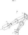
- FIG. 1 is a diagram illustrating the configuration of a spectroscope 10 disclosed in PTL 1.
- the spectroscope 10 includes a first slit array 12, a diffraction grating 14, and a second slit array 17.
- the first slit array 12 has a plurality of slits arranged with a first pitch p1.
- the diffraction grating 14 is a reflection grating characterized by a diffraction angle that changes with respect to a light wavelength (angular dispersion).
- the second slit array 17 has a plurality of slits arranged with a second pitch p2 different from the first pitch p1. In this configuration, the spectrum of input light is measured by detecting a moire pattern generated by overlaying the image of the first slit array 12 (dispersed first fringes) and the second slit array 17 (second fringes).
- Moire patterns are beat patterns generated by displacing the periods of periodic patterns overlaid on one another.
- the position of a moire pattern (the position of a high-intensity region in a moire pattern) considerably changes according to the positional relationship between the periodic patterns. In other words, the position of the moire pattern changes greater than a change of the position of the image of the first slit array 12 according to the wavelength of input light.
- the spectrum of input light can be measured by moire pattern measurement.
- it is necessary to increase an aspect ratio that is, the ratio of the width of a low-intensity region to the width of the high-intensity region for the first fringes and the second fringes.
- the slit widths are however limited in the fabrication. Moreover, a reduction in slit width may increase a light quantity loss, leading to difficulty in measuring the spectrum of weak light. This limits an improvement in the aspect ratio of the slit array (that is, a reduction in opening ratio) and also limits an improvement of spectrum resolving power during the measurement of the spectrum.
- a spectroscope is a spectroscope for measuring a spectrum of input light, and includes: a fringe former that forms first fringes having a first pitch by splitting the input light; a dispersive device that disperses each of the first fringes; a moire pattern former that forms a moire pattern by overlaying the first fringes that have been dispersed, on second fringes having a second pitch different from the first pitch; and a measuring device that measures the spectrum of the input light by detecting the moire pattern, wherein at least one of the fringe former and the moire pattern former includes a cylindrical lens array.
- At least one of the fringe former and the moire pattern former can include a cylindrical lens array.
- the cylindrical lens array can reduce the width of the high-intensity region of the fringe as compared with the slit array because of the effect of condensing light in addition to the effect of reducing the width of the cylindrical lens.
- the cylindrical lens array does not block the input light, thereby suppressing a light quantity loss.
- the spectroscope including the cylindrical lens instead of the slit array can suppress a loss of a light quantity, thereby improving the spectrum resolving power.
- the fringe former may include the cylindrical lens array that forms the first fringes.
- the fringe former can include the cylindrical lens array. This can form a high-intensity region having a small width, that is, the first fringe having a high aspect ratio. Furthermore, this configuration can also suppress a light quantity loss caused by the formation of the first fringes. For example, if the first fringe has an aspect ratio of 10, a light quantity loss can be reduced to one tenth or less than that of the slit array.
- the moire pattern former may include the cylindrical lens array that forms the moire pattern, and the measuring device may detect the moire pattern at a focal position of the cylindrical lens array of the moire pattern former.
- the moire pattern former can include the cylindrical lens array. Hence, a light quantity loss can be smaller than that of the slit array. If the moire pattern former is a slit array, the moire pattern is formed at the position of the slit array. For this reason, in order to eliminate the influence of blurring caused by defocus in the detection of the moire pattern, a relay lens or the like is necessary for forming an image of the moire pattern at a position separated from the slit array. If the moire pattern former is the cylindrical lens array, the moire pattern is formed at the position (focal position) separated from the cylindrical lens array. Thus, the measuring device can detect the moire pattern at the focal position of the cylindrical lens array. Specifically, the measuring device can be disposed at the formation position of the moire pattern, thereby eliminating the need for a relay lens. This can reduce the number of parts, thereby downsizing the spectroscope.
- a spectroscope is a spectroscope for measuring a spectrum of input light, and includes: a fringe former that forms first fringes having a first pitch by splitting the input light; a dispersive device that disperses each of the first fringes; a moire pattern former that forms a moire pattern by overlaying the first fringes that have been dispersed, on second fringes having a second pitch different from the first pitch; and a measuring device that measures the spectrum of the input light by detecting the moire pattern, wherein at least one of the fringe former and the moire pattern former includes a cylindrical lens array.
- the same effect as the spectroscope can suppress a light quantity loss, thereby improving the wavelength resolving power.
- a spectroscope according to an aspect of the present invention can improve spectrum resolving power when measuring a spectrum using a moire pattern.
- FIG. 2 is a diagram illustrating the configuration of a spectroscope 100 according to Embodiment 1.
- FIG. 3 is a perspective view showing a cylindrical lens array 101 according to Embodiment 1.
- the spectroscope 100 includes the cylindrical lens array 101, a first lens 102, a diffraction grating 103, a second lens 104, a slit array 105, a third lens 106, and an image pickup device 107.
- the cylindrical lens array 101 is an example of a fringe former that forms first fringes 111 with a first pitch p1 by splitting input light 110. In other words, the cylindrical lens array 101 reproduces a plurality of linear light beams from the input light 110. As shown in FIG. 3 , the cylindrical lens array 101 has a plurality of cylindrical lenses horizontally placed with the first pitch p1 (e.g., about 0.5 mm).
- each cylindrical lens Light incident on each cylindrical lens is condensed into a corresponding line, thereby forming the first fringes 111 including a plurality of narrow lines.
- This line corresponds to the slit of the slit array and forms a high-intensity region.
- the cylindrical lens array 101 can form the first fringes 111 having an aspect ratio of at least 10.
- the first lens 102 is a collimating lens for condensing the light of the first fringes 111 into parallel rays.
- the diffraction grating 103 is an example of a dispersive device that disperse each of the first fringes.
- the diffraction grating 103 is a reflection grating having the property of changing a diffraction angle with respect to a light wavelength (angular dispersion).
- the dispersive device is not limited to a diffraction grating.
- the second lens 104 is a lens for condensing light dispersed by the diffraction grating 103, onto the slit array 105. In other words, the second lens 104 forms first fringes 112 dispersed on the slit array 105.
- the slit array 105 is an example of a moire pattern former that forms a moire pattern 113 by overlaying the dispersed first fringes 112 on second fringes with a second pitch p2 (e.g., about 0.42 mm) different from the first pitch p1.
- the slit array 105 forms the second fringes with a plurality of slits placed with the second pitch p2 in the same direction as the dispersed first fringes 112.
- the moire pattern is a beat pattern generated by displacing the periods of periodic patterns overlaid on one another.
- the position of the moire pattern (an intensity peak position in the moire pattern) changes according to the positional relationship between periodic patterns.
- the third lens 106 is a lens for forming an image of the moire pattern 113 on the imaging surface of the image pickup device 107, the moire pattern 113 being formed immediately behind the slit array 105.
- the image pickup device 107 is an example of a measuring device that measures the spectrum of the input light 110 by detecting the moire pattern 113.
- the image pickup device 107 is, for example, a solid-state image pickup device such as a CCD (Charge Coupled Device) image sensor or a CMOS (Complementary Metal Oxide Semiconductor) image sensor.
- CCD Charge Coupled Device
- CMOS Complementary Metal Oxide Semiconductor
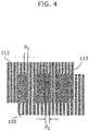
- FIG. 4 is a diagram illustrating an overlap of dispersed first fringes and second fringes according to Embodiment 1.
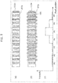
- FIG. 5 shows the moire pattern detection results when the input light 110 is monochromatic light of a first wavelength.
- FIG. 6 shows the moire pattern detection results when the input light 110 is monochromatic light of a second wavelength.
- FIG. 7 is an explanatory drawing of the principle for measuring a spectrum.
- the first fringes 112 dispersed by the diffraction grating 103 form a striped pattern like the first fringes 111.
- the dispersed first fringes 112 has a monochromatic striped pattern like the first fringes 111.
- the dispersed first fringes 112 and the slit array 105 acting as second fringes are overlaid on each other so as to form the moire pattern 113 as illustrated in FIG. 4 .
- the position of the dispersed first fringes 112 depends upon the wavelength of the input light 110, so that the moire pattern 113 also depends upon the wavelength of input light.
- the principle for measuring the spectrum of the input light 110 with the dispersed first fringes 112 and the slit array 105 will be more specifically described below.
- the input light 110 is monochromatic light.
- (a) indicates the positional relationship between the dispersed first fringes 112 and pixels 107p of the image pickup device 107.
- (b) indicates the positional relationship among the dispersed first fringes 112, the pixels 107p of the image pickup device 107, and the slit array 105.
- (c) indicates an intensity detected in each of the pixels 107p of the image pickup device 107.
- Input light having the first wavelength forms first fringes 112a dispersed as illustrated in (a) of FIG. 5 .
- the dispersed first fringes 112a and the slit array 105 are overlaid on each other so as to generate the moire pattern.
- the intensity of the moire pattern is detected in each of the pixels.
- a peak intensity is detected in a pixel P5.
- Input light having the second wavelength forms first fringes 112b dispersed as illustrated in (a) of FIG. 6 .
- the dispersed first fringes 112b are shifted to the right from the dispersed first fringes 112a by a distance smaller than one pixel. This is because the input light of the first wavelength and the input light of the second wavelength have different diffraction angles in the diffraction grating 103.
- the dispersed first fringes 112b and the slit array 105 are overlaid on each other so as to generate the moire pattern.
- the intensity of the moire pattern is detected in each of the pixels.
- a peak intensity is detected in a pixel P4.
- the moire pattern in FIG. 6 is shifted to the left by one pixel from the moire pattern in FIG. 5 .
- the position of the moire pattern generated by an overlap of the dispersed first fringes 112 (vernier scale) and the slit array 105 (main scale) changes greater than the positions of the dispersed first fringes 112. This allows the spectroscope 100 to detect a small positional change of the dispersed first fringes 112, and thereby determine a small difference in the wavelength of input light.
- Such a measurement is called a vernier effect in which two scales (a main scale and a vernier scale) are overlaid on each other with different pitches so as to measure a small change of the vernier scale in an enlarged view.
- the spectroscope 100 can improve spectrum resolving power according to the vernier effect in a band determined by the resolving power of the main scale.
- the intensity of input light containing light with multiple wavelengths can be measured at each wavelength.
- the input light 110 is split by the cylindrical lens array 101 into the first fringes 111.
- the first fringes 111 are further dispersed by the diffraction grating 103 into the dispersed first fringes 112.
- the high-intensity region of the dispersed first fringe 112 has the spectrum distribution of the input light 110.
- the dispersed first fringes 112 and the slit array 105 are overlaid on each other so as to form the moire pattern 113.
- the spectrum distribution of each high-intensity region is extended, thereby improving the resolution of spectrum measurement.
- FIG. 8 is a flowchart showing the method of measuring a spectrum according to Embodiment 1.
- the cylindrical lens array 101 splits the input light 110 so as to form the first fringes 111 (S101).
- the diffraction grating 103 disperses each of the first fringes 111 to form the dispersed first fringes 112 (S102).
- the dispersed first fringes 112 are overlaid on the second fringes formed on the slit array 105, forming the moire pattern 113 (S103).
- the image pickup device 107 measures the spectrum of the input light 110 by detecting the moire pattern 113 (S104).
- a fringe former may include the cylindrical lens array 101.
- the cylindrical lens array 101 On the cylindrical lens array 101, light incident on each cylindrical lens is condensed onto a corresponding line.
- the cylindrical lens array 101 can reduce the width of the high-intensity region of the fringe as compared with the slit array because of the effect of condensing light in addition to the effect of reducing the width of the cylindrical lens.
- the cylindrical lens array 101 does not block the input light 110, thereby suppressing a light quantity loss.
- the spectroscope 100 including the cylindrical lens instead of the slit array can suppress a light quantity loss, thereby improving the spectrum resolving power.
- the fringe former particularly including the cylindrical lens array 101 can form a high-intensity region having a small width, that is, the first fringes with a high aspect ratio. Furthermore, this configuration can also suppress a light quantity loss caused by the formation of the first fringes. For example, if the first fringe has an aspect ratio of 10, a light quantity loss can be reduced to one tenth or less than that of the slit array.
- Embodiment 2 will be described below with reference to the accompanying drawings.
- a spectroscope according to Embodiment 2 is different from Embodiment 1 in that a cylindrical lens array is used instead of a slit array on the output side.
- Embodiment 2 differences from Embodiment 1 will be mainly discussed below.
- FIG. 9 is a diagram illustrating the configuration of a spectroscope 200 according to Embodiment 2.
- FIG. 10 is a perspective view illustrating a cylindrical lens array 205 according to Embodiment 2.
- constituent elements substantially identical to those of FIG. 2 are indicated by the same reference numerals and the explanation thereof is optionally omitted.
- the spectroscope 200 includes a slit array 201, a first lens 102, a diffraction grating 103, a second lens 104, the cylindrical lens array 205, and an image pickup device 207.
- the slit array 201 is an example of a fringe former that forms first fringes 211 with a first pitch p1 by splitting input light 110.
- the slit array 201 has a plurality of slits horizontally arranged with the first pitch p1.
- the first fringes 211 have a plurality of lines horizontally arranged with the first pitch p1.
- the cylindrical lens array 205 is an example of a moire pattern former that forms moire 213 by overlaying the dispersed first fringes 212 on second fringes with a second pitch p2 different from the first pitch p1.
- the cylindrical lens array 205 has a plurality of cylindrical lenses placed with the second pitch p2 in the same direction as the dispersed first fringes 212.
- a moire pattern is formed by overlaying the first fringes and the cylindrical lens array (second fringes) (Non Patent Literature 1: A. Livnat, O. Kafri, "Moire pattern of a linear grid with a lenticular grating", OPTICS LETTERS, Optical Society of America, June 1982, Vol. 7, No. 6, p. 253-255 ).
- the image pickup device 207 is an example of a measuring device that measures the moire pattern 213 at the focal position of the cylindrical lens array 205.
- the image pickup device 207 is, for example, a solid-state image pickup device such as a CCD image sensor or a CMOS image sensor.
- the image pickup device 207 is separated from the cylindrical lens array 205 by a focal distance. No lens may be provided between the image pickup device 207 and the cylindrical lens array 205.
- a moire pattern former may include the cylindrical lens array 205.
- a light quantity loss can be smaller than that of the slit array.
- the moire pattern former is a slit array, the moire pattern is formed at the position of the slit array.
- a relay lens e.g., the third lens 106 of FIG. 2
- the like is necessary for forming an image of the moire pattern at a position separated from the slit array.
- the moire pattern former is the cylindrical lens array 205
- the moire pattern is formed at the position (focal position) separated from the cylindrical lens array 205 by the focal distance.
- the image pickup device 207 can detect the moire pattern at the focal position of the cylindrical lens array 205.
- the image pickup device 207 can be directly disposed at the formation position of the moire pattern, thereby eliminating the need for a relay lens. This can reduce the number of parts of the spectroscope 200, thereby downsizing the spectroscope 200.
- Embodiment 3 will be described below with reference to the accompanying drawings.
- a spectroscope according to Embodiment 3 is different from the Embodiments 1 and 2 in that a cylindrical lens array is used instead of a slit array on each of the input and output sides.
- differences from the Embodiments 1 and 2 will be mainly discussed below.
- FIG. 11 is a diagram illustrating the configuration of a spectroscope 300 according to Embodiment 3.
- constituent elements substantially identical to those of FIGS. 2 and 9 are indicated by the same reference numerals and the explanation thereof is optionally omitted.
- the spectroscope 300 includes a cylindrical lens array 101, a first lens 102, a diffraction grating 103, a second lens 104, a cylindrical lens array 205, and an image pickup device 207.
- the spectroscope 300 includes the two cylindrical lens arrays 101 and 205.
- the cylindrical lens array 101 on the input side forms first fringes 111 by splitting input light 110.
- the cylindrical lens array 205 on the output side forms moire pattern 313 from dispersed first fringes 112.
- the spectroscope 300 can achieve the effects of the Embodiments 1 and 2.
- a slit array does not block light and thus a light quantity loss can be further reduced. Referring to FIGS. 12A and 12B , a reduction in light quantity loss will be discussed below.
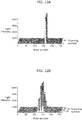
- FIG. 12A is a graph showing the detection results of dispersed light in a typical spectroscope.
- FIG. 12B is a graph showing the moire pattern detection results in the spectroscope according to Embodiment 3.
- the typical spectroscope is a spectroscope that measures a spectrum by only using the angular dispersion property of a diffraction grating without a moire pattern.
- a pixel number indicates a horizontal position of the image pickup device and a scanning number indicates a vertical position of the image pickup device.
- the intensity of light indicates light intensity measured at each pixel of the image pickup device.
- the detection results of input light are shown in the graphs.
- the input light is monochromatic light.
- the peak value of light intensity hardly changes between the typical spectroscope and the spectroscope according to Embodiment 3, proving that a light quantity loss for forming the moire pattern is suppressed.
- a plurality of convex lenses are formed on one surface of the cylindrical lens array.
- the shapes of the lenses are not limited thereto.
- the cylindrical lens array may be formed by changing a refractive index in the lens.
- the cylindrical lens array may not have any convex lenses.
- the convex lenses may be formed on both surfaces of the array.
- the cylindrical lens array may have any shape as long as the array has optical functions identical or similar to those of the cylindrical lens arrays described in the embodiments.
- the spectroscope may have an optical filter for cutting light at wavelengths outside the measurement band.
- Light having passed through the wavelength filter is used as input light, so that the spectrum of the input light can be measured with high accuracy within the measurement band.
- the passband of the wavelength filter may be changed with the passage of time.
- the spectrum of input light can be measured in multiple measurement bands.
- a dispersive device used in the embodiments is not limited to the diffraction grating.
- the dispersive device may be a prism or an etalon.
- a measuring device used in the embodiments is not limited to the image pickup device.
- the measuring device may be a photodetector or a photosensitive film.
- the spectroscope including the first lens and the second lens in the embodiments may not include the lenses.
- the first lens or the second lens may be integrated with the cylindrical lens array.
- the spectroscope for measuring the spectrum of input light may be obtained as a wavelength measuring device for measuring the wavelength of input light.
- the measuring device only needs to measure the wavelength of input light by detecting the moire pattern. This can suppress a light quantity loss, thereby improving wavelength resolving power.
- a spectroscope according to one aspect of the present invention can improve resolving power when measuring the spectrum of input light.
- the spectroscope is applicable to a Raman spectroscope.
Landscapes
- Physics & Mathematics (AREA)
- Spectroscopy & Molecular Physics (AREA)
- General Physics & Mathematics (AREA)
- Engineering & Computer Science (AREA)
- Computer Vision & Pattern Recognition (AREA)
- Optics & Photonics (AREA)
- Spectrometry And Color Measurement (AREA)
Applications Claiming Priority (2)
| Application Number | Priority Date | Filing Date | Title |
|---|---|---|---|
| JP2016137012A JP6749633B2 (ja) | 2016-07-11 | 2016-07-11 | 分光器、波長測定装置及びスペクトル測定方法 |
| PCT/JP2017/024479 WO2018012351A1 (ja) | 2016-07-11 | 2017-07-04 | 分光器、波長測定装置及びスペクトル測定方法 |
Publications (3)
| Publication Number | Publication Date |
|---|---|
| EP3483573A1 true EP3483573A1 (de) | 2019-05-15 |
| EP3483573A4 EP3483573A4 (de) | 2020-04-15 |
| EP3483573B1 EP3483573B1 (de) | 2022-03-02 |
Family
ID=60952052
Family Applications (1)
| Application Number | Title | Priority Date | Filing Date |
|---|---|---|---|
| EP17827481.7A Not-in-force EP3483573B1 (de) | 2016-07-11 | 2017-07-04 | Spektroskop und spektrumsmessverfahren |
Country Status (5)
| Country | Link |
|---|---|
| US (1) | US10801893B2 (de) |
| EP (1) | EP3483573B1 (de) |
| JP (1) | JP6749633B2 (de) |
| CN (1) | CN109716079B (de) |
| WO (1) | WO2018012351A1 (de) |
Family Cites Families (16)
| Publication number | Priority date | Publication date | Assignee | Title |
|---|---|---|---|---|
| FR2072056B1 (de) * | 1969-12-24 | 1974-09-27 | Shimadzu Corp | |
| JP2992192B2 (ja) * | 1994-03-08 | 1999-12-20 | シャープ株式会社 | 3次元情報再生装置 |
| US5519533A (en) | 1994-03-08 | 1996-05-21 | Sharp Kabushiki Kaisha | Three-dimensional information reproducing apparatus |
| JP3473989B2 (ja) * | 1994-05-20 | 2003-12-08 | 株式会社ワコム | 情報入力装置 |
| JP3135107B2 (ja) * | 1995-06-27 | 2001-02-13 | シャープ株式会社 | 3次元ディスプレイ装置 |
| US5835217A (en) * | 1997-02-28 | 1998-11-10 | The Regents Of The University Of California | Phase-shifting point diffraction interferometer |
| US6084712A (en) * | 1998-11-03 | 2000-07-04 | Dynamic Measurement And Inspection,Llc | Three dimensional imaging using a refractive optic design |
| JP3494964B2 (ja) * | 2000-07-28 | 2004-02-09 | 株式会社山武 | 表面形状測定装置 |
| EP2400260A1 (de) | 2002-02-14 | 2011-12-28 | OPDI Technologies A/S | Optischer Weggeber |
| US7626708B2 (en) * | 2006-04-28 | 2009-12-01 | Chao-Wen Liang | Phase shifting grating-slit test for optical surface reconstruction |
| KR100956852B1 (ko) * | 2008-03-24 | 2010-05-11 | 선문대학교 산학협력단 | Lcd패널을 이용한 모아레 형상측정장치 |
| GB201003397D0 (en) * | 2010-03-01 | 2010-04-14 | Rue De Int Ltd | Moire magnification security device |
| JP2013050441A (ja) * | 2011-08-03 | 2013-03-14 | Canon Inc | 波面測定装置、波面測定方法、及びプログラム並びにx線撮像装置 |
| JP2013183108A (ja) * | 2012-03-02 | 2013-09-12 | Sony Corp | 照明光学系、分光測定用光照射装置及び分光測定装置 |
| JP6445814B2 (ja) * | 2014-09-11 | 2018-12-26 | 国立大学法人大阪大学 | 分光器およびスペクトル測定方法 |
| DE102014226269A1 (de) * | 2014-12-17 | 2016-06-23 | Carl Zeiss Smt Gmbh | Wellenfrontmesseinrichtung, Projektionsobjektiv mit einer solchen Messeinrichtung und mit einer solchen Messeinrichtung zusammenwirkender optischer Wellenfrontmanipulator |
-
2016
- 2016-07-11 JP JP2016137012A patent/JP6749633B2/ja active Active
-
2017
- 2017-07-04 CN CN201780041393.2A patent/CN109716079B/zh active Active
- 2017-07-04 WO PCT/JP2017/024479 patent/WO2018012351A1/ja not_active Ceased
- 2017-07-04 EP EP17827481.7A patent/EP3483573B1/de not_active Not-in-force
- 2017-07-04 US US16/316,928 patent/US10801893B2/en active Active
Also Published As
| Publication number | Publication date |
|---|---|
| US10801893B2 (en) | 2020-10-13 |
| WO2018012351A1 (ja) | 2018-01-18 |
| EP3483573B1 (de) | 2022-03-02 |
| JP2018009813A (ja) | 2018-01-18 |
| US20190301938A1 (en) | 2019-10-03 |
| CN109716079B (zh) | 2021-04-06 |
| JP6749633B2 (ja) | 2020-09-02 |
| CN109716079A (zh) | 2019-05-03 |
| EP3483573A4 (de) | 2020-04-15 |
Similar Documents
| Publication | Publication Date | Title |
|---|---|---|
| EP2466281B1 (de) | Spektroskopiedetektor | |
| US8908087B2 (en) | Multiband camera, and multiband image capturing method | |
| JP5880053B2 (ja) | 分光特性取得装置及び画像形成装置 | |
| CN114599946B (zh) | 光谱仪和成像装置 | |
| EP2918968A2 (de) | Messvorrichtung und verfahren zur herstellung eines artikels | |
| CN108344508A (zh) | 一种宽光谱范围非对称空间外差光谱仪 | |
| EP3315927B1 (de) | Spektraldetektor und spektraldetektionsverfahren damit | |
| KR101054017B1 (ko) | 분광기의 보정방법 | |
| EP3483573B1 (de) | Spektroskop und spektrumsmessverfahren | |
| JP7033968B2 (ja) | 分光装置、ハイパースペクトル測定システム、及び、分光方法 | |
| US12235157B2 (en) | Spectrometry device | |
| US10481004B2 (en) | Light wavelength measurement method and light wavelength measurement apparatus | |
| WO2013140016A1 (en) | An apparatus and a method for imaging | |
| JP6445814B2 (ja) | 分光器およびスペクトル測定方法 | |
| US20220229213A1 (en) | Diffraction element and imaging device | |
| JPWO2021044979A5 (de) | ||
| JP2009145068A (ja) | 表面形状の測定方法および干渉計 | |
| JP6130805B2 (ja) | 距離測定装置および方法 | |
| WO2020203592A1 (ja) | 光検出装置、光検出方法、光検出装置の設計方法、試料分類方法、及び、不良検出方法 | |
| JP6260157B2 (ja) | 分光測定装置 | |
| JP4297830B2 (ja) | 撮像装置およびその使用方法 | |
| JP2001116618A (ja) | 分光計 | |
| JP2017111020A (ja) | ラインスキャナ装置 | |
| JP2015055480A5 (de) |
Legal Events
| Date | Code | Title | Description |
|---|---|---|---|
| STAA | Information on the status of an ep patent application or granted ep patent |
Free format text: STATUS: THE INTERNATIONAL PUBLICATION HAS BEEN MADE |
|
| PUAI | Public reference made under article 153(3) epc to a published international application that has entered the european phase |
Free format text: ORIGINAL CODE: 0009012 |
|
| STAA | Information on the status of an ep patent application or granted ep patent |
Free format text: STATUS: REQUEST FOR EXAMINATION WAS MADE |
|
| 17P | Request for examination filed |
Effective date: 20190207 |
|
| AK | Designated contracting states |
Kind code of ref document: A1 Designated state(s): AL AT BE BG CH CY CZ DE DK EE ES FI FR GB GR HR HU IE IS IT LI LT LU LV MC MK MT NL NO PL PT RO RS SE SI SK SM TR |
|
| AX | Request for extension of the european patent |
Extension state: BA ME |
|
| DAV | Request for validation of the european patent (deleted) | ||
| DAX | Request for extension of the european patent (deleted) | ||
| A4 | Supplementary search report drawn up and despatched |
Effective date: 20200312 |
|
| RIC1 | Information provided on ipc code assigned before grant |
Ipc: G01J 3/28 20060101ALI20200306BHEP Ipc: G02B 27/60 20060101ALI20200306BHEP Ipc: G01J 3/45 20060101AFI20200306BHEP Ipc: G01J 9/02 20060101ALI20200306BHEP Ipc: G01J 3/453 20060101ALI20200306BHEP Ipc: G01J 3/04 20060101ALI20200306BHEP |
|
| GRAP | Despatch of communication of intention to grant a patent |
Free format text: ORIGINAL CODE: EPIDOSNIGR1 |
|
| STAA | Information on the status of an ep patent application or granted ep patent |
Free format text: STATUS: GRANT OF PATENT IS INTENDED |
|
| INTG | Intention to grant announced |
Effective date: 20210927 |
|
| GRAS | Grant fee paid |
Free format text: ORIGINAL CODE: EPIDOSNIGR3 |
|
| GRAA | (expected) grant |
Free format text: ORIGINAL CODE: 0009210 |
|
| STAA | Information on the status of an ep patent application or granted ep patent |
Free format text: STATUS: THE PATENT HAS BEEN GRANTED |
|
| AK | Designated contracting states |
Kind code of ref document: B1 Designated state(s): AL AT BE BG CH CY CZ DE DK EE ES FI FR GB GR HR HU IE IS IT LI LT LU LV MC MK MT NL NO PL PT RO RS SE SI SK SM TR |
|
| REG | Reference to a national code |
Ref country code: GB Ref legal event code: FG4D |
|
| REG | Reference to a national code |
Ref country code: CH Ref legal event code: EP Ref country code: AT Ref legal event code: REF Ref document number: 1472625 Country of ref document: AT Kind code of ref document: T Effective date: 20220315 |
|
| REG | Reference to a national code |
Ref country code: DE Ref legal event code: R096 Ref document number: 602017054150 Country of ref document: DE |
|
| REG | Reference to a national code |
Ref country code: IE Ref legal event code: FG4D |
|
| REG | Reference to a national code |
Ref country code: LT Ref legal event code: MG9D |
|
| REG | Reference to a national code |
Ref country code: NL Ref legal event code: MP Effective date: 20220302 |
|
| PG25 | Lapsed in a contracting state [announced via postgrant information from national office to epo] |
Ref country code: SE Free format text: LAPSE BECAUSE OF FAILURE TO SUBMIT A TRANSLATION OF THE DESCRIPTION OR TO PAY THE FEE WITHIN THE PRESCRIBED TIME-LIMIT Effective date: 20220302 Ref country code: RS Free format text: LAPSE BECAUSE OF FAILURE TO SUBMIT A TRANSLATION OF THE DESCRIPTION OR TO PAY THE FEE WITHIN THE PRESCRIBED TIME-LIMIT Effective date: 20220302 Ref country code: NO Free format text: LAPSE BECAUSE OF FAILURE TO SUBMIT A TRANSLATION OF THE DESCRIPTION OR TO PAY THE FEE WITHIN THE PRESCRIBED TIME-LIMIT Effective date: 20220602 Ref country code: LT Free format text: LAPSE BECAUSE OF FAILURE TO SUBMIT A TRANSLATION OF THE DESCRIPTION OR TO PAY THE FEE WITHIN THE PRESCRIBED TIME-LIMIT Effective date: 20220302 Ref country code: HR Free format text: LAPSE BECAUSE OF FAILURE TO SUBMIT A TRANSLATION OF THE DESCRIPTION OR TO PAY THE FEE WITHIN THE PRESCRIBED TIME-LIMIT Effective date: 20220302 Ref country code: ES Free format text: LAPSE BECAUSE OF FAILURE TO SUBMIT A TRANSLATION OF THE DESCRIPTION OR TO PAY THE FEE WITHIN THE PRESCRIBED TIME-LIMIT Effective date: 20220302 Ref country code: BG Free format text: LAPSE BECAUSE OF FAILURE TO SUBMIT A TRANSLATION OF THE DESCRIPTION OR TO PAY THE FEE WITHIN THE PRESCRIBED TIME-LIMIT Effective date: 20220602 |
|
| REG | Reference to a national code |
Ref country code: AT Ref legal event code: MK05 Ref document number: 1472625 Country of ref document: AT Kind code of ref document: T Effective date: 20220302 |
|
| PG25 | Lapsed in a contracting state [announced via postgrant information from national office to epo] |
Ref country code: PL Free format text: LAPSE BECAUSE OF FAILURE TO SUBMIT A TRANSLATION OF THE DESCRIPTION OR TO PAY THE FEE WITHIN THE PRESCRIBED TIME-LIMIT Effective date: 20220302 Ref country code: LV Free format text: LAPSE BECAUSE OF FAILURE TO SUBMIT A TRANSLATION OF THE DESCRIPTION OR TO PAY THE FEE WITHIN THE PRESCRIBED TIME-LIMIT Effective date: 20220302 Ref country code: GR Free format text: LAPSE BECAUSE OF FAILURE TO SUBMIT A TRANSLATION OF THE DESCRIPTION OR TO PAY THE FEE WITHIN THE PRESCRIBED TIME-LIMIT Effective date: 20220603 Ref country code: FI Free format text: LAPSE BECAUSE OF FAILURE TO SUBMIT A TRANSLATION OF THE DESCRIPTION OR TO PAY THE FEE WITHIN THE PRESCRIBED TIME-LIMIT Effective date: 20220302 |
|
| PG25 | Lapsed in a contracting state [announced via postgrant information from national office to epo] |
Ref country code: NL Free format text: LAPSE BECAUSE OF FAILURE TO SUBMIT A TRANSLATION OF THE DESCRIPTION OR TO PAY THE FEE WITHIN THE PRESCRIBED TIME-LIMIT Effective date: 20220302 |
|
| PG25 | Lapsed in a contracting state [announced via postgrant information from national office to epo] |
Ref country code: SM Free format text: LAPSE BECAUSE OF FAILURE TO SUBMIT A TRANSLATION OF THE DESCRIPTION OR TO PAY THE FEE WITHIN THE PRESCRIBED TIME-LIMIT Effective date: 20220302 Ref country code: SK Free format text: LAPSE BECAUSE OF FAILURE TO SUBMIT A TRANSLATION OF THE DESCRIPTION OR TO PAY THE FEE WITHIN THE PRESCRIBED TIME-LIMIT Effective date: 20220302 Ref country code: RO Free format text: LAPSE BECAUSE OF FAILURE TO SUBMIT A TRANSLATION OF THE DESCRIPTION OR TO PAY THE FEE WITHIN THE PRESCRIBED TIME-LIMIT Effective date: 20220302 Ref country code: PT Free format text: LAPSE BECAUSE OF FAILURE TO SUBMIT A TRANSLATION OF THE DESCRIPTION OR TO PAY THE FEE WITHIN THE PRESCRIBED TIME-LIMIT Effective date: 20220704 Ref country code: EE Free format text: LAPSE BECAUSE OF FAILURE TO SUBMIT A TRANSLATION OF THE DESCRIPTION OR TO PAY THE FEE WITHIN THE PRESCRIBED TIME-LIMIT Effective date: 20220302 Ref country code: CZ Free format text: LAPSE BECAUSE OF FAILURE TO SUBMIT A TRANSLATION OF THE DESCRIPTION OR TO PAY THE FEE WITHIN THE PRESCRIBED TIME-LIMIT Effective date: 20220302 Ref country code: AT Free format text: LAPSE BECAUSE OF FAILURE TO SUBMIT A TRANSLATION OF THE DESCRIPTION OR TO PAY THE FEE WITHIN THE PRESCRIBED TIME-LIMIT Effective date: 20220302 |
|
| PGFP | Annual fee paid to national office [announced via postgrant information from national office to epo] |
Ref country code: DE Payment date: 20220621 Year of fee payment: 6 |
|
| PG25 | Lapsed in a contracting state [announced via postgrant information from national office to epo] |
Ref country code: IS Free format text: LAPSE BECAUSE OF FAILURE TO SUBMIT A TRANSLATION OF THE DESCRIPTION OR TO PAY THE FEE WITHIN THE PRESCRIBED TIME-LIMIT Effective date: 20220702 Ref country code: AL Free format text: LAPSE BECAUSE OF FAILURE TO SUBMIT A TRANSLATION OF THE DESCRIPTION OR TO PAY THE FEE WITHIN THE PRESCRIBED TIME-LIMIT Effective date: 20220302 |
|
| PGFP | Annual fee paid to national office [announced via postgrant information from national office to epo] |
Ref country code: FR Payment date: 20220727 Year of fee payment: 6 |
|
| REG | Reference to a national code |
Ref country code: DE Ref legal event code: R097 Ref document number: 602017054150 Country of ref document: DE |
|
| PLBE | No opposition filed within time limit |
Free format text: ORIGINAL CODE: 0009261 |
|
| STAA | Information on the status of an ep patent application or granted ep patent |
Free format text: STATUS: NO OPPOSITION FILED WITHIN TIME LIMIT |
|
| PG25 | Lapsed in a contracting state [announced via postgrant information from national office to epo] |
Ref country code: DK Free format text: LAPSE BECAUSE OF FAILURE TO SUBMIT A TRANSLATION OF THE DESCRIPTION OR TO PAY THE FEE WITHIN THE PRESCRIBED TIME-LIMIT Effective date: 20220302 |
|
| 26N | No opposition filed |
Effective date: 20221205 |
|
| PG25 | Lapsed in a contracting state [announced via postgrant information from national office to epo] |
Ref country code: SI Free format text: LAPSE BECAUSE OF FAILURE TO SUBMIT A TRANSLATION OF THE DESCRIPTION OR TO PAY THE FEE WITHIN THE PRESCRIBED TIME-LIMIT Effective date: 20220302 Ref country code: MC Free format text: LAPSE BECAUSE OF FAILURE TO SUBMIT A TRANSLATION OF THE DESCRIPTION OR TO PAY THE FEE WITHIN THE PRESCRIBED TIME-LIMIT Effective date: 20220302 |
|
| REG | Reference to a national code |
Ref country code: CH Ref legal event code: PL |
|
| GBPC | Gb: european patent ceased through non-payment of renewal fee |
Effective date: 20220704 |
|
| REG | Reference to a national code |
Ref country code: BE Ref legal event code: MM Effective date: 20220731 |
|
| PG25 | Lapsed in a contracting state [announced via postgrant information from national office to epo] |
Ref country code: LU Free format text: LAPSE BECAUSE OF NON-PAYMENT OF DUE FEES Effective date: 20220704 Ref country code: LI Free format text: LAPSE BECAUSE OF NON-PAYMENT OF DUE FEES Effective date: 20220731 Ref country code: CH Free format text: LAPSE BECAUSE OF NON-PAYMENT OF DUE FEES Effective date: 20220731 |
|
| PG25 | Lapsed in a contracting state [announced via postgrant information from national office to epo] |
Ref country code: GB Free format text: LAPSE BECAUSE OF NON-PAYMENT OF DUE FEES Effective date: 20220704 Ref country code: BE Free format text: LAPSE BECAUSE OF NON-PAYMENT OF DUE FEES Effective date: 20220731 |
|
| PG25 | Lapsed in a contracting state [announced via postgrant information from national office to epo] |
Ref country code: IT Free format text: LAPSE BECAUSE OF FAILURE TO SUBMIT A TRANSLATION OF THE DESCRIPTION OR TO PAY THE FEE WITHIN THE PRESCRIBED TIME-LIMIT Effective date: 20220302 Ref country code: IE Free format text: LAPSE BECAUSE OF NON-PAYMENT OF DUE FEES Effective date: 20220704 |
|
| REG | Reference to a national code |
Ref country code: DE Ref legal event code: R119 Ref document number: 602017054150 Country of ref document: DE |
|
| PG25 | Lapsed in a contracting state [announced via postgrant information from national office to epo] |
Ref country code: HU Free format text: LAPSE BECAUSE OF FAILURE TO SUBMIT A TRANSLATION OF THE DESCRIPTION OR TO PAY THE FEE WITHIN THE PRESCRIBED TIME-LIMIT; INVALID AB INITIO Effective date: 20170704 |
|
| PG25 | Lapsed in a contracting state [announced via postgrant information from national office to epo] |
Ref country code: MK Free format text: LAPSE BECAUSE OF FAILURE TO SUBMIT A TRANSLATION OF THE DESCRIPTION OR TO PAY THE FEE WITHIN THE PRESCRIBED TIME-LIMIT Effective date: 20220302 Ref country code: DE Free format text: LAPSE BECAUSE OF NON-PAYMENT OF DUE FEES Effective date: 20240201 Ref country code: CY Free format text: LAPSE BECAUSE OF FAILURE TO SUBMIT A TRANSLATION OF THE DESCRIPTION OR TO PAY THE FEE WITHIN THE PRESCRIBED TIME-LIMIT Effective date: 20220302 |
|
| PG25 | Lapsed in a contracting state [announced via postgrant information from national office to epo] |
Ref country code: FR Free format text: LAPSE BECAUSE OF NON-PAYMENT OF DUE FEES Effective date: 20230731 |
|
| PG25 | Lapsed in a contracting state [announced via postgrant information from national office to epo] |
Ref country code: MT Free format text: LAPSE BECAUSE OF FAILURE TO SUBMIT A TRANSLATION OF THE DESCRIPTION OR TO PAY THE FEE WITHIN THE PRESCRIBED TIME-LIMIT Effective date: 20220302 |
|
| PG25 | Lapsed in a contracting state [announced via postgrant information from national office to epo] |
Ref country code: TR Free format text: LAPSE BECAUSE OF FAILURE TO SUBMIT A TRANSLATION OF THE DESCRIPTION OR TO PAY THE FEE WITHIN THE PRESCRIBED TIME-LIMIT Effective date: 20220302 |