EP3483539A1 - Bin assembly - Google Patents
Bin assembly Download PDFInfo
- Publication number
- EP3483539A1 EP3483539A1 EP18204975.9A EP18204975A EP3483539A1 EP 3483539 A1 EP3483539 A1 EP 3483539A1 EP 18204975 A EP18204975 A EP 18204975A EP 3483539 A1 EP3483539 A1 EP 3483539A1
- Authority
- EP
- European Patent Office
- Prior art keywords
- locking member
- bin assembly
- opening
- cover
- cavity
- Prior art date
- Legal status (The legal status is an assumption and is not a legal conclusion. Google has not performed a legal analysis and makes no representation as to the accuracy of the status listed.)
- Granted
Links
Images




Classifications
-
- F—MECHANICAL ENGINEERING; LIGHTING; HEATING; WEAPONS; BLASTING
- F25—REFRIGERATION OR COOLING; COMBINED HEATING AND REFRIGERATION SYSTEMS; HEAT PUMP SYSTEMS; MANUFACTURE OR STORAGE OF ICE; LIQUEFACTION SOLIDIFICATION OF GASES
- F25D—REFRIGERATORS; COLD ROOMS; ICE-BOXES; COOLING OR FREEZING APPARATUS NOT OTHERWISE PROVIDED FOR
- F25D25/00—Charging, supporting, and discharging the articles to be cooled
- F25D25/02—Charging, supporting, and discharging the articles to be cooled by shelves
- F25D25/024—Slidable shelves
- F25D25/025—Drawers
-
- F—MECHANICAL ENGINEERING; LIGHTING; HEATING; WEAPONS; BLASTING
- F25—REFRIGERATION OR COOLING; COMBINED HEATING AND REFRIGERATION SYSTEMS; HEAT PUMP SYSTEMS; MANUFACTURE OR STORAGE OF ICE; LIQUEFACTION SOLIDIFICATION OF GASES
- F25D—REFRIGERATORS; COLD ROOMS; ICE-BOXES; COOLING OR FREEZING APPARATUS NOT OTHERWISE PROVIDED FOR
- F25D23/00—General constructional features
- F25D23/02—Doors; Covers
- F25D23/028—Details
-
- F—MECHANICAL ENGINEERING; LIGHTING; HEATING; WEAPONS; BLASTING
- F25—REFRIGERATION OR COOLING; COMBINED HEATING AND REFRIGERATION SYSTEMS; HEAT PUMP SYSTEMS; MANUFACTURE OR STORAGE OF ICE; LIQUEFACTION SOLIDIFICATION OF GASES
- F25D—REFRIGERATORS; COLD ROOMS; ICE-BOXES; COOLING OR FREEZING APPARATUS NOT OTHERWISE PROVIDED FOR
- F25D2325/00—Charging, supporting or discharging the articles to be cooled, not provided for in other groups of this subclass
- F25D2325/021—Shelves with several possible configurations
Definitions
- the present disclosure generally relates to a bin assembly. More specifically, the present disclosure relates to a roller assembly for the bin assembly that may be used inside a refrigerator.
- bin assemblies include roller assemblies mounted to the side of the assemblies using an axle configured to screw directly into the side of the bin assembly. It is desired to create a more robust roller assembly for a bin assembly.
- a bin assembly comprises a substrate defining a compartment.
- the compartment includes a central portion, a first lateral portion, and a second lateral portion, and a cavity is formed within each lateral portion.
- a locking member is configured to extend through an opening defined in an exterior wall of each lateral portion.
- the locking member includes a flange protruding perpendicularly from the locking member.
- a cover e.g. made of POM material, is secured to the locking member and the substrate to inhibit rotation of the locking member.
- a rotatable member is coupled to the locking member and is configured to move the bin assembly between a stowed position and a deployed position.
- a bin assembly comprises a substrate having a bottom surface and a perimeter wall defining a compartment with a front portion and a back portion.
- the substrate further defines a cavity and an opening.
- the bin assembly further comprises a locking member with a center portion and two protrusions.
- the two protrusions extend in opposing directions from the center portion, and a flange extends from the locking member and is oriented perpendicularly to the center portion.
- a cover further secures the locking member and the two protrusions to prevent the locking member from rotating.
- a wheel is operably coupled to an aperture defined by the locking member.
- a bin assembly comprises a substrate defining a compartment and a cavity external to the compartment.
- a locking member is disposed within an opening defined by an exterior wall of the cavity, and a flange extends from the locking member.
- a cover is coupled with the locking member on an opposing side of the substrate from the flange, and a rotatable member is operably coupled with an aperture defined by the cover, the locking member, and the exterior wall of the cavity.
- the term "and/or,” when used in a list of two or more items, means that any one of the listed items can be employed by itself, or any combination of two or more of the listed items, can be employed.
- the composition can contain A alone; B alone; C alone; A and B in combination; A and C in combination; B and C in combination; or A, B, and C in combination.
- FIGS. 1-8 provide exemplary features, aspects, and embodiments for a bin assembly 16 located within a refrigeration appliance 10 including a cabinet 14.
- the cabinet 14 may include storage shelves 12 and bin assemblies 16.
- the bin assemblies 16 may be comprised of a substrate 32 defining a compartment 34 including a central portion 84, a first lateral portion 76, and a second lateral portion 80.
- a cavity 78, 82 is formed within each lateral portion 76, 80, and each cavity 78, 82 houses a locking member 200.
- the locking member 200 includes a flange 204 protruding perpendicularly from the locking member 200.
- the locking member 200 is configured to extend through an opening 100 defined in an exterior wall 98 of each lateral portion 76, 80.
- a cover 300 secured to the locking member 200 and the exterior wall 98 to prevent undesired rotation of the locking member 200.
- a rotatable member 400 is also coupled to the locking member 200 and is configured to move the bin assembly 16 between a stowed position and a deployed position.
- the locking member 200, the cover 300 and/or the rotatable member 400 may advantageously be made of polyoxymethylene (POM), known for its good fatigue/creep resistance, low friction and good performance at cold temperatures.
- POM polyoxymethylene
- the numeral 10 generally denotes a refrigeration appliance including a cabinet 14 that defines a refrigeration chamber 18 selectively closeable by a pair of refrigeration chamber doors 22 and a freezer chamber 26 selectively closeable by a freezer chamber door 30.
- the refrigeration chamber 18 and the freezer chamber 26 act as storage compartments within the cabinet 14. Included within the refrigeration chamber 18 and the freezer chamber 26 may be storage shelves 12 and bin assemblies 16.
- the bin assemblies 16 may act as drawers for a variety of purposes including, for example, a crisper drawer.
- a French door bottom-mount refrigeration appliance 10 is shown where the freezer chamber 26 is located below the refrigeration chamber 18.
- the refrigeration appliance 10 could be a side-by-side refrigeration appliance, a refrigeration appliance with the freezer chamber positioned above the refrigeration chamber (top-mount refrigeration), a refrigeration appliance that includes only a refrigeration chamber and no freezer chamber, etc.
- the bin assembly 16 is shown having a substrate 32 defining the compartment 34.
- the compartment includes a bottom surface 36 and two spaced-apart sidewalls 40, 42 joined together by a front wall 44 and a back wall 46. Together, the sidewalls 40, 42, the front wall 44, and the back wall 46 define a compartment perimeter wall 38.
- the bottom surface 36 and the compartment perimeter wall 38 may be integrally formed.
- Each sidewall 40, 42 includes a forward sidewall 48, 50 and a rear sidewall 52, 54.
- the rear sidewall 52, 54 is of a first height.
- the forward sidewall 48, 50 extends upward from the rear sidewall 52, 54 to form a first step 56, 58 of a second height.
- the forward sidewall 48, 50 may extend again upward from the first step 56, 58 to form a second step 60, 62 of a third height.
- the second steps 60, 62 are of the same third height as and may be integrally formed with the front wall 44.
- the rear sidewalls 52, 54 may be integrally formed with and are of the same first height as the back wall 46.
- a handle 70 is disposed on the front wall 44 and is configured to aid in moving the bin assembly 16 between the stowed position and the deployed position.
- the bin assembly 16 In the stowed position, the bin assembly 16 may be disposed within the refrigeration chamber 18.
- the bin assembly 16 In the deployed position, the bin assembly 16 may be disposed outwardly of the refrigeration chamber 18.
- the handle 70 in the embodiment shown is a finger pull, the handle 70 may be any feature useful for opening and closing a drawer such as, for example, a knob, bar handle, T-bar handle, recessed handle, appliance pull, bail pull, or flush pull.
- the compartment 34 is also subdivided into a front portion 72 and a back portion 74.
- the front portion 72 includes two laterally extending spaces 73a, 73b that extend outward to conceal the back portion 74 when the bin assembly 16 is viewed from the front.
- the back portion 74 can also be divided into a first lateral portion 76, a second lateral portion 80 and a central portion 84.
- the first and second lateral portions 76, 80 may each include a stepped surface 86, 88 that provides space for a track member to be used with the bin assembly 16 if desired. It will be appreciated that the bin assembly may not include such a stepped surface and that the overall shape of the compartment may vary depending on the application of the bin assembly.
- lateral portions 76, 80 are also hidden from view by the front portion 72 when the bin assembly 16 is viewed from the front. Included in these lateral portions 76, 80 are cavities 78, 82 each having an exterior wall 98 defining an opening 100.
- a roller assembly 90 is operably coupled to each opening 100 such that the roller assemblies 90 are hidden from view by the laterally extending spaces 73a, 73b when the bin assembly 16 is viewed from the front, as shown in FIGS. 2 and 3 .
- the roller assembly 90 includes the locking member 200, the cover 300, and the rotatable member 400.
- the roller assembly 90 is operably coupled to the opening 100 defined by the exterior wall 98 of the lateral portions 76, 80.
- each cavity has a perimeter wall 94 with an exterior wall 98.
- the exterior wall 98 defines an opening 100.
- Each cavity 78, 82 may house the locking member 200.
- the locking member 200 includes a flange 204 having a front surface 208 and a back surface 212.
- the flange 204 is integrally formed with the locking member 200 such that the locking member 200 extends perpendicularly through the flange 204.
- the flange 204 includes a first portion 214 and a second portion 218.
- the first portion 214 may be narrower than the second portion 218, creating a handle 222 for moving the locking member 200.
- the second portion 218 also extends past the locking member 200 to protrude from the opposite side of the locking member 200.
- the locking member 200 has a cylindrical center portion 229 and includes first and second protrusions 228, 230, as best seen in FIG. 4B .
- the center portion 229 and the first and second protrusions 228, 230 are configured to extend through the opening 100. It will be appreciated that the center portion 229 may be of any geometry without departing from the scope of the present disclosure.
- the protrusions 228, 230 extend in opposing directions from the cylindrical center portion 229.
- the opening 100 includes a rim 104 that surrounds the opening 100.
- the rim 104 consists of a first raised portion 108.
- the first raised portion 108 includes a first outer lip 110 that sits flush with the exterior wall 98 of the cavity 78, 82.
- the first raised portion 108 is configured to align with the shape of the locking member 200 to allow the locking member 200 to pass through the opening 100 when the locking member is in a first, mounting position.
- a second raised portion 112 extends from the first raised portion 108 and forms a second outer lip 114.
- the second raised portion 112 may be smaller in surface area than the first raised portion 108 and may also frame the opening 100 in the same way the first raised portion 108 does.
- An extension 118 is integrally formed with the second raised portion 112 and defines a perimeter wall 122 with a top surface 124.
- the perimeter wall 122 is in the shape of a circle with two indentions 128, 130 configured to divide the circle into two arcs 134, 136.
- Each arc 134, 136 begins and ends at one wall of the indentions 128, 130 of the perimeter wall 122 and extends to the opposite wall of the other indention 128, 130.
- the indentions 128, 130 and the arcs 134, 136 form a contact surface that defines a predefined magnitude of rotation for the locking member in a first direction when disposed within the opening
- the protrusions 228, 230 may have a thickness greater than the distance from the second raised portion 112 of the rim 104 to the perimeter wall 122 that allow the locking member 200 to protrude past the rim 104 when coupled to the opening 100. This allows the protrusions 228, 230 of the locking member 200 to rotate a predefined distance around the arcs 134, 136 before being stopped by one of the indentions 128, 130 of the perimeter wall 122 and also allows the cover 300 to connect to the locking member 200.
- the locking member 200 is shown within the opening 100 and in a first position.
- the cylindrical center portion 229 and the protrusions 228, 230 are disposed in the opening 100 and may be framed by the perimeter wall 122.
- the protrusions 228, 230 are oriented horizontally and may be flush against, or contact, a first side of the indentions 128, 130 of the perimeter wall 122.
- the flange 204 may be oriented vertically, and the locking member 200 is set within the opening 100 so that the front surface 208 of the flange 204 may sit along the substrate 32 forming the exterior wall 98 of the cavity 78, 82.
- the locking member 200 can be rotated in a first direction along arrow R from the first, mounting position to a second, assembly position.
- the indentions 128, 130 prevent the locking member 200 from rotating beyond the second, assembly position, while the flange acts as a stopper in the axial direction.
- the locking member 200 is shown coupled with the opening 100 and rotated to a second position so that the protrusions 228, 230 have rotated from sitting horizontally aligned with a first indention 128, 130 to sitting vertically aligned with a second indention 128, 130 on the opposite side of the arc 134, 136.
- the flange 204 is oriented horizontally within the cavity 78, 82 in the second position and is configured to sit between a dividing wall 140 and the exterior wall 98.
- the dividing wall 140 is disposed within the cavity 78, 82 and is configured to extend from the perimeter wall 94 of the cavity 78, 82.
- the locking member 200 is shown coupled to the opening 100 in the second position.
- a cover 300 is also shown separated from the locking member 200 and the opening 100.
- the cover 300 is configured to engage with the rim 104 of the opening 100 on an opposing side of the substrate 32 from the flange 204.
- the cover 300 is circular to mimic the shape of the rim 104.
- An inner portion 304 of the cover 300 is configured to couple with the first raised portion 108, the first outer lip 110, the second raised portion 112, and/or the second outer lip 114 of the opening 100.
- the cover 300 may be shaped to couple with the substrate 32 around the opening 100, and may be of any shape or dimension.
- the cover 300 includes the inner portion 304 and an outer portion 308.
- the cover 300 also includes a first portion 312 and a second portion 316 with the second portion 316 being raised from the first portion 312.
- the first portion 312 couples with the substrate 32 and the rim 104 while the second portion 316 couples with the perimeter wall 122.
- the second portion 316 may be configured to cover or surround the perimeter wall 122, and/or cover the arcs 134, 136 and/or the indentions 128, 130.
- the second portion 316 also defines an opening 320 that receives the locking member 200.
- the opening 320 includes spaces 324 to receive the protrusions 228, 230 in the second position.
- the configuration of the cover 300 is such that when it is coupled to the locking member 200 and the substrate 32, the protrusions 228, 230 received in the spaces 324 inhibit rotation of the locking member 200 in a second direction, which is opposite the first direction indicated by arrow R as seen in FIG. 6A . More generally, the locking member 200 and the cover 300 are configured to form a shape coupling in the second assembly position, thereby inhibiting rotation of the locking member 200 in a direction opposite to the first direction R, which would result in risk to dislodge the locking member 200 from the opening 100.
- the roller assembly 90 is shown with the cover 300 maintaining the locking member 200 in place in the second position.
- a rotatable member 400 Separated from the roller assembly 90 is a rotatable member 400.
- the rotatable member 400 in the embodiment shown, includes a wheel 404 operably coupled with an axle 408.
- the axle 408, in turn, operably couples the wheel 404 to the locking member 200.
- the wheel 404 may be integrally formed with the axle 408.
- the axle 408 couples with an aperture 440 that is defined by the cover 300, the locking member 200, the rim 104, and the exterior wall 98 of the cavity 78, 82 to allow the wheel 404 to rotate.
- the axle 408 may be coupled to the locking member 200 in any way known in the art, including, for example, having the axle 408 threaded or otherwise releasably or fixably retained to the locking member 200 or having the axle 408 integrally formed with the locking member 200.
- the wheel 404 includes an outer surface 412 and an inner surface 416.
- the axle 408 extends from the inner surface 416 and is oriented perpendicularly to the wheel 404 along the axis of rotation of the wheel 404.
- the wheel 404 also includes a center wheel portion 420 and two lateral wheel portions 422, 424 on either side of the center wheel portion 420.
- the center wheel portion 420 and the lateral wheel portions 422, 424 include rolling surfaces 430, 432, 434 to allow the wheel 404 to move forward or backward as the wheel 404 rotates.
- the wheel 404 in the present embodiment, is independent from the rest of the refrigeration appliance 10 and is coupled to the bin assembly 16.
- the bin assembly could be coupled to a track member for easier movement between the stowed position and the deployed position.
- the track member may be of any practicable design.
- bin assembly may provide various advantages. For example, it may prevent various problems such as breaking the pan when screwing the axle into the bin assembly, causing a failure of the pan boss area while screwing in or testing the roller assembly, or creating a chock hazard because of failure at the pan boss location. It may also increase pan reliability as the roller assembly no longer directly touches the part, reducing the wear and tear on both pieces.
- a bin assembly may be provided that includes a substrate defining a compartment including a central portion, a first lateral portion, and a second lateral portion, wherein a cavity is formed within each lateral portion.
- a locking member may include a flange protruding perpendicularly from the locking member, wherein the locking member may be configured to extend through an opening defined in an exterior wall of each lateral portion.
- a cover may be secured to the locking member and the substrate, wherein the cover may inhibit rotation of the locking member.
- a rotatable member may be coupled to the locking member and configured to move the bin assembly between a stowed position and a deployed position.
- the locking member may be disposed in a first position within the opening and can be rotatable from the first position to a second position.
- the opening may be further defined by a rim configured to prevent the locking member from rotating beyond the second position.
- the flange may be positioned within the cavity when the locking member is in the second position.
- the rotatable member may include a wheel and an axle.
- the axle may be operably coupled to an aperture defined by the locking member, the aperture further extending through the cover and the substrate.
- the axle may be integrally formed with the locking member.
- a bin assembly may be provided that includes a substrate having a bottom surface and a perimeter wall defining a compartment with a front portion and a back portion, the substrate further defining a cavity and an opening.
- a locking member may have a center portion and two protrusions, the two protrusions extending in opposing directions from the center portion, and a flange extending from the locking member and perpendicularly to the center portion.
- a cover may secure the locking member and the two protrusions to prevent the locking member from rotating.
- a wheel may be operably coupled to an aperture defined by the locking member.
- the bottom surface and the perimeter wall may be integrally formed, and wherein a stepped surface may be defined along each lateral portion of the back portion of the compartment.
- a dividing wall may extend into the cavity.
- the locking member and the two protrusions may be disposed in the opening and allow the locking member to rotate in a first direction.
- the opening may be further defined by an at least one outer lip, the outer lip having a contact surface that defines a predefined magnitude of rotation for the locking member in the first direction when disposed within the opening.
- the cover may be configured to prevent rotation of the locking member in a second direction, the second direction opposite the first direction.
- the bin assembly may include an axle configured to extend through the aperture and into the cavity and operably coupling the wheel to the locking member.
- a bin assembly may be provided that includes a substrate defining a compartment and a cavity external to the compartment.
- a locking member may have a flange extending therefrom, wherein the locking member may be disposed within an opening defined by an exterior wall of the cavity.
- a cover may be coupled with the locking member on an opposing side of the substrate from the flange.
- a rotatable member may be operably coupled with an aperture defined by the cover, the locking member, and the exterior wall of the cavity.
- the locking member may rotate from a first position to a second position.
- the flange may be positioned within the cavity when the locking member is in the second position, and wherein the locking member is engaged with the substrate in the second position.
- the cover may be configured to couple with the substrate to inhibit rotation of the locking member, thereby securing the locking member in the second position.
- the rotatable member may include a wheel and an axle.
- the axle may be integrally formed with the wheel.
Landscapes
- Engineering & Computer Science (AREA)
- Chemical & Material Sciences (AREA)
- Combustion & Propulsion (AREA)
- Physics & Mathematics (AREA)
- Mechanical Engineering (AREA)
- Thermal Sciences (AREA)
- General Engineering & Computer Science (AREA)
- Devices That Are Associated With Refrigeration Equipment (AREA)
- Handcart (AREA)
Abstract
Description
- The present disclosure generally relates to a bin assembly. More specifically, the present disclosure relates to a roller assembly for the bin assembly that may be used inside a refrigerator.
- Currently bin assemblies include roller assemblies mounted to the side of the assemblies using an axle configured to screw directly into the side of the bin assembly. It is desired to create a more robust roller assembly for a bin assembly.
- According to a first aspect of the present disclosure, a bin assembly comprises a substrate defining a compartment. The compartment includes a central portion, a first lateral portion, and a second lateral portion, and a cavity is formed within each lateral portion. A locking member is configured to extend through an opening defined in an exterior wall of each lateral portion. The locking member includes a flange protruding perpendicularly from the locking member. A cover, e.g. made of POM material, is secured to the locking member and the substrate to inhibit rotation of the locking member. A rotatable member is coupled to the locking member and is configured to move the bin assembly between a stowed position and a deployed position.
- According to a second aspect of the present disclosure, a bin assembly comprises a substrate having a bottom surface and a perimeter wall defining a compartment with a front portion and a back portion. The substrate further defines a cavity and an opening. The bin assembly further comprises a locking member with a center portion and two protrusions. The two protrusions extend in opposing directions from the center portion, and a flange extends from the locking member and is oriented perpendicularly to the center portion. A cover further secures the locking member and the two protrusions to prevent the locking member from rotating. A wheel is operably coupled to an aperture defined by the locking member.
- According to a third aspect of the present disclosure, a bin assembly comprises a substrate defining a compartment and a cavity external to the compartment. A locking member is disposed within an opening defined by an exterior wall of the cavity, and a flange extends from the locking member. A cover is coupled with the locking member on an opposing side of the substrate from the flange, and a rotatable member is operably coupled with an aperture defined by the cover, the locking member, and the exterior wall of the cavity.
- These and other aspects, objects, and features of the present disclosure will be understood and appreciated by those skilled in the art upon studying the following specification, claims, and appended drawings.
- In the drawings:
-
FIG. 1 is a front perspective view of a refrigeration appliance according to one aspect; -
FIG. 2 is a side perspective view of a bin assembly with a wheel assembly; -
FIG. 3 is an exploded view of the wheel assembly and the bin assembly; -
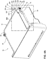
FIG. 4A is a bottom perspective view of the bin assembly with a locking member; -
FIG. 4B is an enhanced view of the locking member as shown inFIG. 4A ; -
FIG. 5A is a side enhanced elevational view of the opening and the locking member; -
FIG. 5B is a cross-sectional view of the wheel assembly taken along the line VB-VB ofFIG. 5A ; -
FIG. 6A is an enhanced view of the locking member shown inFIG. 4A with the locking member in a first position; -
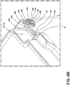
FIG. 6B is an enhanced view of the locking member shown inFIG. 4A with the locking member in a second position; -
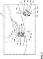
FIG. 7 is a side perspective view of the locking member with a cover separated from the locking member; and -
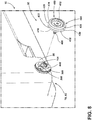
FIG. 8 is a side perspective view of the locking member and the cover with a wheel separated from the locking member. - For purposes of description herein, the terms "upper," "lower," "right," "left," "rear," "front," "vertical," "horizontal," and derivatives thereof shall relate to the concepts as oriented in
FIG. 1 . - As used herein, the term "and/or," when used in a list of two or more items, means that any one of the listed items can be employed by itself, or any combination of two or more of the listed items, can be employed. For example, if a composition is described as containing components A, B, and/or C, the composition can contain A alone; B alone; C alone; A and B in combination; A and C in combination; B and C in combination; or A, B, and C in combination.
- By way of illustration,
FIGS. 1-8 provide exemplary features, aspects, and embodiments for abin assembly 16 located within arefrigeration appliance 10 including acabinet 14. Thecabinet 14 may includestorage shelves 12 andbin assemblies 16. Thebin assemblies 16 may be comprised of asubstrate 32 defining acompartment 34 including acentral portion 84, a firstlateral portion 76, and a secondlateral portion 80. Acavity lateral portion cavity locking member 200. Thelocking member 200 includes aflange 204 protruding perpendicularly from thelocking member 200. Thelocking member 200 is configured to extend through anopening 100 defined in anexterior wall 98 of eachlateral portion bin assembly 16 is acover 300 secured to thelocking member 200 and theexterior wall 98 to prevent undesired rotation of thelocking member 200. Arotatable member 400 is also coupled to thelocking member 200 and is configured to move thebin assembly 16 between a stowed position and a deployed position. Thelocking member 200, thecover 300 and/or therotatable member 400 may advantageously be made of polyoxymethylene (POM), known for its good fatigue/creep resistance, low friction and good performance at cold temperatures. - Referring now to
FIG. 1 , thenumeral 10 generally denotes a refrigeration appliance including acabinet 14 that defines arefrigeration chamber 18 selectively closeable by a pair ofrefrigeration chamber doors 22 and afreezer chamber 26 selectively closeable by afreezer chamber door 30. Therefrigeration chamber 18 and thefreezer chamber 26 act as storage compartments within thecabinet 14. Included within therefrigeration chamber 18 and thefreezer chamber 26 may bestorage shelves 12 andbin assemblies 16. Thebin assemblies 16 may act as drawers for a variety of purposes including, for example, a crisper drawer. InFIG.1 , a French door bottom-mount refrigeration appliance 10 is shown where thefreezer chamber 26 is located below therefrigeration chamber 18. Although one particular design of therefrigeration appliance 10 is shown inFIG. 1 , other refrigerator styles and configurations are contemplated. For example, therefrigeration appliance 10 could be a side-by-side refrigeration appliance, a refrigeration appliance with the freezer chamber positioned above the refrigeration chamber (top-mount refrigeration), a refrigeration appliance that includes only a refrigeration chamber and no freezer chamber, etc. - Referring now to
FIG. 2 , thebin assembly 16 is shown having asubstrate 32 defining thecompartment 34. The compartment includes abottom surface 36 and two spaced-apartsidewalls front wall 44 and aback wall 46. Together, thesidewalls front wall 44, and theback wall 46 define acompartment perimeter wall 38. Thebottom surface 36 and thecompartment perimeter wall 38 may be integrally formed. Eachsidewall forward sidewall rear sidewall rear sidewall forward sidewall rear sidewall first step forward sidewall first step second step front wall 44. Similarly, therear sidewalls back wall 46. - Still referring to
FIG. 2 , ahandle 70 is disposed on thefront wall 44 and is configured to aid in moving thebin assembly 16 between the stowed position and the deployed position. In the stowed position, thebin assembly 16 may be disposed within therefrigeration chamber 18. In the deployed position, thebin assembly 16 may be disposed outwardly of therefrigeration chamber 18. While thehandle 70 in the embodiment shown is a finger pull, thehandle 70 may be any feature useful for opening and closing a drawer such as, for example, a knob, bar handle, T-bar handle, recessed handle, appliance pull, bail pull, or flush pull. - Referring again to
FIG. 2 , thecompartment 34 is also subdivided into afront portion 72 and aback portion 74. Thefront portion 72 includes two laterally extendingspaces back portion 74 when thebin assembly 16 is viewed from the front. Theback portion 74 can also be divided into a firstlateral portion 76, a secondlateral portion 80 and acentral portion 84. The first and secondlateral portions surface bin assembly 16 if desired. It will be appreciated that the bin assembly may not include such a stepped surface and that the overall shape of the compartment may vary depending on the application of the bin assembly. Theselateral portions front portion 72 when thebin assembly 16 is viewed from the front. Included in theselateral portions cavities exterior wall 98 defining anopening 100. Aroller assembly 90 is operably coupled to eachopening 100 such that theroller assemblies 90 are hidden from view by the laterally extendingspaces bin assembly 16 is viewed from the front, as shown inFIGS. 2 and3 . - Referring now to
FIG. 3 , thebin assembly 16 is shown with aroller assembly 90 exploded away from thecompartment 34. Theroller assembly 90 includes the lockingmember 200, thecover 300, and therotatable member 400. Theroller assembly 90 is operably coupled to theopening 100 defined by theexterior wall 98 of thelateral portions - Referring now to
FIGS. 4A and4B , thebin assembly 16 is shown withcavities substrate 32 external to thecompartment 34 and disposed within thelateral portions perimeter wall 94 with anexterior wall 98. Theexterior wall 98 defines anopening 100. Eachcavity member 200. The lockingmember 200 includes aflange 204 having afront surface 208 and aback surface 212. Theflange 204 is integrally formed with the lockingmember 200 such that the lockingmember 200 extends perpendicularly through theflange 204. Theflange 204 includes afirst portion 214 and asecond portion 218. Thefirst portion 214 may be narrower than thesecond portion 218, creating ahandle 222 for moving the lockingmember 200. Thesecond portion 218 also extends past the lockingmember 200 to protrude from the opposite side of the lockingmember 200. - Still referring to
FIGS. 4A and4B , the lockingmember 200, as shown, has acylindrical center portion 229 and includes first andsecond protrusions FIG. 4B . Thecenter portion 229 and the first andsecond protrusions opening 100. It will be appreciated that thecenter portion 229 may be of any geometry without departing from the scope of the present disclosure. Theprotrusions cylindrical center portion 229. - As best shown in
FIG. 5A , theopening 100 includes arim 104 that surrounds theopening 100. Therim 104 consists of a first raisedportion 108. The first raisedportion 108 includes a firstouter lip 110 that sits flush with theexterior wall 98 of thecavity portion 108 is configured to align with the shape of the lockingmember 200 to allow the lockingmember 200 to pass through theopening 100 when the locking member is in a first, mounting position. A second raisedportion 112 extends from the first raisedportion 108 and forms a secondouter lip 114. The second raisedportion 112 may be smaller in surface area than the first raisedportion 108 and may also frame theopening 100 in the same way the first raisedportion 108 does. Anextension 118 is integrally formed with the second raisedportion 112 and defines aperimeter wall 122 with atop surface 124. In this embodiment, theperimeter wall 122 is in the shape of a circle with twoindentions arcs arc indentions perimeter wall 122 and extends to the opposite wall of theother indention indentions arcs - As shown in
FIG. 5B , theprotrusions portion 112 of therim 104 to theperimeter wall 122 that allow the lockingmember 200 to protrude past therim 104 when coupled to theopening 100. This allows theprotrusions member 200 to rotate a predefined distance around thearcs indentions perimeter wall 122 and also allows thecover 300 to connect to the lockingmember 200. - Referring now to
FIG. 6A , the lockingmember 200 is shown within theopening 100 and in a first position. Thecylindrical center portion 229 and theprotrusions opening 100 and may be framed by theperimeter wall 122. In this first position, theprotrusions indentions perimeter wall 122. Theflange 204 may be oriented vertically, and the lockingmember 200 is set within theopening 100 so that thefront surface 208 of theflange 204 may sit along thesubstrate 32 forming theexterior wall 98 of thecavity member 200 can be rotated in a first direction along arrow R from the first, mounting position to a second, assembly position. Theindentions member 200 from rotating beyond the second, assembly position, while the flange acts as a stopper in the axial direction. - Referring now to
FIG. 6B , the lockingmember 200 is shown coupled with theopening 100 and rotated to a second position so that theprotrusions first indention second indention arc flange 204 is oriented horizontally within thecavity wall 140 and theexterior wall 98. The dividingwall 140 is disposed within thecavity perimeter wall 94 of thecavity - Referring now to
FIG. 7 , the lockingmember 200 is shown coupled to theopening 100 in the second position. Acover 300 is also shown separated from the lockingmember 200 and theopening 100. Thecover 300 is configured to engage with therim 104 of theopening 100 on an opposing side of thesubstrate 32 from theflange 204. In some examples, thecover 300 is circular to mimic the shape of therim 104. Aninner portion 304 of thecover 300 is configured to couple with the first raisedportion 108, the firstouter lip 110, the second raisedportion 112, and/or the secondouter lip 114 of theopening 100. As illustrated, thecover 300 may be shaped to couple with thesubstrate 32 around theopening 100, and may be of any shape or dimension. - Referring still to
FIG. 7 , thecover 300 includes theinner portion 304 and anouter portion 308. Thecover 300 also includes afirst portion 312 and asecond portion 316 with thesecond portion 316 being raised from thefirst portion 312. Thefirst portion 312 couples with thesubstrate 32 and therim 104 while thesecond portion 316 couples with theperimeter wall 122. Thesecond portion 316 may be configured to cover or surround theperimeter wall 122, and/or cover thearcs indentions second portion 316 also defines anopening 320 that receives the lockingmember 200. Theopening 320 includesspaces 324 to receive theprotrusions cover 300 is such that when it is coupled to the lockingmember 200 and thesubstrate 32, theprotrusions spaces 324 inhibit rotation of the lockingmember 200 in a second direction, which is opposite the first direction indicated by arrow R as seen inFIG. 6A . More generally, the lockingmember 200 and thecover 300 are configured to form a shape coupling in the second assembly position, thereby inhibiting rotation of the lockingmember 200 in a direction opposite to the first direction R, which would result in risk to dislodge the lockingmember 200 from theopening 100. - Referring now to
FIG. 8 , theroller assembly 90 is shown with thecover 300 maintaining the lockingmember 200 in place in the second position. Separated from theroller assembly 90 is arotatable member 400. Therotatable member 400, in the embodiment shown, includes awheel 404 operably coupled with anaxle 408. Theaxle 408, in turn, operably couples thewheel 404 to the lockingmember 200. Alternatively, thewheel 404 may be integrally formed with theaxle 408. Theaxle 408 couples with anaperture 440 that is defined by thecover 300, the lockingmember 200, therim 104, and theexterior wall 98 of thecavity wheel 404 to rotate. Theaxle 408 may be coupled to the lockingmember 200 in any way known in the art, including, for example, having theaxle 408 threaded or otherwise releasably or fixably retained to the lockingmember 200 or having theaxle 408 integrally formed with the lockingmember 200. Thewheel 404 includes anouter surface 412 and aninner surface 416. Theaxle 408 extends from theinner surface 416 and is oriented perpendicularly to thewheel 404 along the axis of rotation of thewheel 404. Thewheel 404 also includes acenter wheel portion 420 and twolateral wheel portions center wheel portion 420. Thecenter wheel portion 420 and thelateral wheel portions surfaces wheel 404 to move forward or backward as thewheel 404 rotates. - Referring still to
FIG. 8 , thewheel 404, in the present embodiment, is independent from the rest of therefrigeration appliance 10 and is coupled to thebin assembly 16. However, it is contemplated that the bin assembly could be coupled to a track member for easier movement between the stowed position and the deployed position. The track member may be of any practicable design. - Use of the bin assembly may provide various advantages. For example, it may prevent various problems such as breaking the pan when screwing the axle into the bin assembly, causing a failure of the pan boss area while screwing in or testing the roller assembly, or creating a chock hazard because of failure at the pan boss location. It may also increase pan reliability as the roller assembly no longer directly touches the part, reducing the wear and tear on both pieces.
- In one aspect, a bin assembly may be provided that includes a substrate defining a compartment including a central portion, a first lateral portion, and a second lateral portion, wherein a cavity is formed within each lateral portion. A locking member may include a flange protruding perpendicularly from the locking member, wherein the locking member may be configured to extend through an opening defined in an exterior wall of each lateral portion. A cover may be secured to the locking member and the substrate, wherein the cover may inhibit rotation of the locking member. A rotatable member may be coupled to the locking member and configured to move the bin assembly between a stowed position and a deployed position.
- According to another aspect, the locking member may be disposed in a first position within the opening and can be rotatable from the first position to a second position.
- According to yet another aspect, the opening may be further defined by a rim configured to prevent the locking member from rotating beyond the second position.
- According to still another aspect, the flange may be positioned within the cavity when the locking member is in the second position.
- According to other aspects, the rotatable member may include a wheel and an axle.
- According to still other aspects, the axle may be operably coupled to an aperture defined by the locking member, the aperture further extending through the cover and the substrate.
- According to another aspect, the axle may be integrally formed with the locking member.
- According to still another aspect, a bin assembly may be provided that includes a substrate having a bottom surface and a perimeter wall defining a compartment with a front portion and a back portion, the substrate further defining a cavity and an opening. A locking member may have a center portion and two protrusions, the two protrusions extending in opposing directions from the center portion, and a flange extending from the locking member and perpendicularly to the center portion. A cover may secure the locking member and the two protrusions to prevent the locking member from rotating. A wheel may be operably coupled to an aperture defined by the locking member.
- According to other aspects, the bottom surface and the perimeter wall may be integrally formed, and wherein a stepped surface may be defined along each lateral portion of the back portion of the compartment.
- According to still other aspects, a dividing wall may extend into the cavity.
- According to yet other aspects, the locking member and the two protrusions may be disposed in the opening and allow the locking member to rotate in a first direction.
- According to another aspect, the opening may be further defined by an at least one outer lip, the outer lip having a contact surface that defines a predefined magnitude of rotation for the locking member in the first direction when disposed within the opening.
- According to still another aspect, the cover may be configured to prevent rotation of the locking member in a second direction, the second direction opposite the first direction.
- According to other aspects, the bin assembly may include an axle configured to extend through the aperture and into the cavity and operably coupling the wheel to the locking member.
- According to still other aspects, a bin assembly may be provided that includes a substrate defining a compartment and a cavity external to the compartment. A locking member may have a flange extending therefrom, wherein the locking member may be disposed within an opening defined by an exterior wall of the cavity. A cover may be coupled with the locking member on an opposing side of the substrate from the flange. A rotatable member may be operably coupled with an aperture defined by the cover, the locking member, and the exterior wall of the cavity.
- According to yet other aspects, the locking member may rotate from a first position to a second position.
- According to another aspect, the flange may be positioned within the cavity when the locking member is in the second position, and wherein the locking member is engaged with the substrate in the second position.
- According to still another aspect, the cover may be configured to couple with the substrate to inhibit rotation of the locking member, thereby securing the locking member in the second position.
- According to other aspects, the rotatable member may include a wheel and an axle.
- According to still other aspects, the axle may be integrally formed with the wheel.
Claims (14)
- A bin assembly (16) comprising:a substrate (32) defining a compartment (34) and a cavity (78, 82) external to the compartment (34);a locking member (200) having a flange (204) extending therefrom, wherein the locking member (200) is disposed within an opening (100) defined by an exterior wall (98) of the cavity (78, 82) and is rotatable in a first direction (R) from a first, mounting position to a second, assembly position;a cover (300) configured to be coupled with the locking member (200) on an opposing side of the substrate (32) from the flange (204) in said second, assembly position; anda rotatable member (400) operably coupled with an aperture (440) defined by the cover (300), the locking member (200), and the exterior wall (98) of the cavity (78, 82),wherein the locking member (200) and the cover (300) are configured to form a shape coupling in said second, assembly position, thereby inhibiting rotation of the locking member (200) relative to the opening (100).
- The bin assembly (16) of claim 1, wherein the locking member (200), the cover (300) and/or the rotatable member (400) are made of POM.
- The bin assembly (16) of claim 1 or 2, wherein the flange (204) is positioned within the cavity (78, 82) when the locking member (200) is in the second position, and wherein the locking member (200) is engaged with the substrate (32) in the second position.
- The bin assembly (16) of claim any one or more of claims 1-3, wherein the rotatable member (400) includes a wheel (404) and an axle (408).
- The bin assembly (16) of claim 4, wherein the axle (408) is integrally formed with the wheel (404).
- The bin assembly (16) of claim 4, wherein the axle (408) is operably coupled to the aperture (440).
- The bin assembly (16) any one or more of claims 1-6, wherein the opening (100) is further defined by an at least one outer lip (110), the outer lip (110) having a contact surface that defines a predefined magnitude of rotation for the locking member (200) in a first direction when disposed within the opening (100).
- The bin assembly (16) any one or more of claims 1-7, wherein the substrate (32) further comprises a bottom surface (36) and a perimeter wall (38) defining a compartment (34) with a front portion (72) and a back portion (74), and wherein a stepped surface (86, 88) is defined along each lateral portion (76, 80) of the back portion (74) of the compartment (34).
- The bin assembly (16) any one or more of claims 1-8, wherein a dividing wall (140) extends into the cavity (78, 82).
- The bin assembly (16) any one or more of claims 1-9, wherein the locking member (200) includes a center portion (229) and two protrusions (228, 230), the two protrusions (228, 230) extending in opposing directions from the center portion (229).
- The bin assembly (16) of claim 10, wherein the locking member (200) and the two protrusions (228, 230) are disposed in the opening (100) and allow the locking member (200) to rotate in a first direction.
- The bin assembly (16) any one or more of claims 1-3, further comprising a wheel (404) operably coupled to the aperture (440).
- The bin assembly (16) any one or more of claims 1-12, wherein the cover (300) is configured to couple with the substrate (32) to inhibit rotation of the locking member (200), thereby securing the locking member (200) in the second position.
- The bin assembly (16) any one or more of claims 1-13, wherein the opening (100) is further defined by a rim (104) configured to prevent the locking member (200) from rotating beyond the second position.
Applications Claiming Priority (1)
| Application Number | Priority Date | Filing Date | Title |
|---|---|---|---|
| US15/807,117 US10371436B2 (en) | 2017-11-08 | 2017-11-08 | Bin assembly |
Publications (2)
| Publication Number | Publication Date |
|---|---|
| EP3483539A1 true EP3483539A1 (en) | 2019-05-15 |
| EP3483539B1 EP3483539B1 (en) | 2022-05-18 |
Family
ID=64183990
Family Applications (1)
| Application Number | Title | Priority Date | Filing Date |
|---|---|---|---|
| EP18204975.9A Active EP3483539B1 (en) | 2017-11-08 | 2018-11-07 | Bin assembly |
Country Status (2)
| Country | Link |
|---|---|
| US (1) | US10371436B2 (en) |
| EP (1) | EP3483539B1 (en) |
Families Citing this family (8)
| Publication number | Priority date | Publication date | Assignee | Title |
|---|---|---|---|---|
| US10914507B2 (en) * | 2017-06-06 | 2021-02-09 | Whirlpool Corporation | Appliance bin |
| USD1059429S1 (en) * | 2021-01-06 | 2025-01-28 | Sub-Zero Group, Inc. | Door shelf |
| USD1076998S1 (en) * | 2022-01-25 | 2025-05-27 | Lg Electronics Inc. | Drawer for refrigerator |
| TWD223468S (en) * | 2022-01-25 | 2023-02-01 | 南韓商Lg電子股份有限公司 | Drawer for refrigerator |
| TWD223467S (en) * | 2022-01-25 | 2023-02-01 | 南韓商Lg電子股份有限公司 | Drawer for refrigerator |
| US20250216148A1 (en) * | 2023-12-29 | 2025-07-03 | Midea Group Co., Ltd. | Refrigeration system and container assemblies |
| USD1098213S1 (en) * | 2024-08-22 | 2025-10-14 | Zhejiang Fontal Technology Co., Ltd | Food storage container |
| USD1098214S1 (en) * | 2024-08-22 | 2025-10-14 | Zhejiang Fontal Technology Co., Ltd | Food storage container |
Citations (5)
| Publication number | Priority date | Publication date | Assignee | Title |
|---|---|---|---|---|
| DE202006007339U1 (en) * | 2006-05-08 | 2006-07-13 | BSH Bosch und Siemens Hausgeräte GmbH | Impeller for a rail-guided refrigerated goods carrier |
| CN202126135U (en) * | 2011-06-13 | 2012-01-25 | 苏州三星电子有限公司 | Refrigerator and strengthening support device for drawer roller of refrigerator |
| US20120222267A1 (en) * | 2011-03-02 | 2012-09-06 | Enertec Consultants Inc. | Damper roller system |
| KR20140088376A (en) * | 2013-01-02 | 2014-07-10 | 동부대우전자 주식회사 | Roller apparatus for refrigerator |
| KR20170065775A (en) * | 2015-12-04 | 2017-06-14 | 삼성전자주식회사 | Refrigerator |
Family Cites Families (250)
| Publication number | Priority date | Publication date | Assignee | Title |
|---|---|---|---|---|
| US774117A (en) | 1904-03-04 | 1904-11-01 | John L Tandy | Display-cabinet. |
| US1952148A (en) | 1929-07-01 | 1934-03-27 | Frigidaire Corp | Refrigerating apparatus |
| US1997432A (en) | 1932-02-01 | 1935-04-09 | Copeland Refrigeration Corp | Shelf construction |
| US2065391A (en) | 1933-10-19 | 1936-12-22 | Gen Motors Corp | Refrigerating apparatus |
| US2273918A (en) * | 1934-08-15 | 1942-02-24 | Zalkind Philip | Container and part therefor |
| US2187916A (en) | 1936-01-23 | 1940-01-23 | Seeger Refrigerator Co | Refrigerator |
| US2225762A (en) | 1937-11-30 | 1940-12-24 | Westinghouse Electric & Mfg Co | Oven rack glide |
| US2282342A (en) | 1940-01-26 | 1942-05-12 | Gen Motors Corp | Refrigerating apparatus |
| US2412904A (en) | 1941-12-10 | 1946-12-17 | Crosley Corp | Refrigerating apparatus |
| US2434117A (en) | 1941-12-10 | 1948-01-06 | Avco Mfg Corp | Shelf structure with guard for refrigerator doors |
| US2466360A (en) | 1945-12-15 | 1949-04-05 | Union Steel Prod Co | Rack assembly for refrigerators, ovens, and the like |
| US2517385A (en) | 1947-04-04 | 1950-08-01 | Int Harvester Co | Fold-away shelf for refrigerators or the like |
| US2573272A (en) | 1947-07-21 | 1951-10-30 | Gen Motors Corp | Storage drawer for refrigerating apparatus |
| US2509592A (en) | 1947-08-15 | 1950-05-30 | Nash Kelvinator Corp | Refrigerating apparatus having receptacle secured to door |
| US2597267A (en) | 1949-11-29 | 1952-05-20 | Philco Corp | Refrigerator having an evaporator provided with a movable section |
| US2694906A (en) | 1951-12-05 | 1954-11-23 | Gen Motors Corp | Refrigerating apparatus having a hydrator receptacle |
| US2773677A (en) | 1952-05-03 | 1956-12-11 | Whirlpool Seeger Corp | Inner liner with butter compartment for refrigerator door |
| US2710993A (en) | 1952-07-09 | 1955-06-21 | Gen Electric | Insulated door structures |
| US2737782A (en) | 1953-01-06 | 1956-03-13 | Philco Corp | Plural compartment refrigerator |
| US2748573A (en) | 1953-01-21 | 1956-06-05 | Philco Corp | Refrigerator having an adjustable evaporator construction |
| US2742559A (en) | 1953-02-12 | 1956-04-17 | Edelman Irving | Removable tray support for rotisserie |
| US2804068A (en) | 1953-03-12 | 1957-08-27 | Admiral Corp | Adjustable oven rack |
| US2875016A (en) | 1954-07-22 | 1959-02-24 | Gen Motors Corp | Domestic appliances |
| US2841132A (en) | 1954-10-25 | 1958-07-01 | American Motors Corp | Range |
| US3164418A (en) * | 1957-08-19 | 1965-01-05 | Illinois Tool Works | Plastic roller |
| US3266858A (en) | 1964-03-12 | 1966-08-16 | American Motors Corp | Refrigerator cabinet storage compartment construction |
| US3295904A (en) | 1964-12-18 | 1967-01-03 | Westinghouse Electric Corp | Container assembly |
| US3410260A (en) | 1966-10-31 | 1968-11-12 | Borg Warner | Liner support useable with oven enclosures or the like |
| US3866437A (en) | 1973-09-10 | 1975-02-18 | Westinghouse Electric Corp | Adjustable damper control mechanism |
| US3984163A (en) | 1975-12-22 | 1976-10-05 | General Electric Company | Cantilever sliding shelf including a shelf removal notch on one side only |
| US4638644A (en) | 1978-04-07 | 1987-01-27 | Edward Gidseg | Circulating air refrigerator with removable divider shelf |
| DE10208058B4 (en) | 2002-02-25 | 2018-10-25 | BSH Hausgeräte GmbH | The refrigerator |
| US4595247A (en) * | 1983-12-07 | 1986-06-17 | Alto-Shaam, Inc. | Food cabinet drawer support |
| US4597616A (en) | 1984-10-30 | 1986-07-01 | Cari-All Inc. | Drawer-like container assembly |
| US4735470A (en) | 1986-03-28 | 1988-04-05 | General Electric Company | Refrigerator including a secondary food storage arrangement |
| US4732435A (en) | 1986-11-07 | 1988-03-22 | Whirlpool Corporation | Refrigerator crisper drawer structure |
| US4729613A (en) | 1986-11-13 | 1988-03-08 | General Electric Company | Household refrigerator pan assembly |
| US5040856A (en) * | 1987-02-27 | 1991-08-20 | Sub-Zero Freezer Company, Inc. | Comestible storage compartment for refrigeration unit |
| DE8710846U1 (en) | 1987-08-05 | 1987-10-01 | Siemens Ag, 1000 Berlin Und 8000 Muenchen | Bracket for a guide roller on a support part |
| DE8801508U1 (en) | 1988-02-06 | 1989-06-08 | Licentia Patent-Verwaltungs-Gmbh, 6000 Frankfurt | Storage area with built-in drawer, especially for household refrigerators and fridge-freezers |
| US4914928A (en) | 1988-08-29 | 1990-04-10 | Whirlpool Corporation | Manual air damper control for a refrigerator |
| US4998382A (en) | 1989-12-11 | 1991-03-12 | Ardco, Inc. | Insulated refrigerator door assembly with substantially all glass front doors |
| US5088801A (en) | 1990-06-12 | 1992-02-18 | Westinghouse Electric Corp. | File holders and briefcase therefor |
| US5273354A (en) | 1991-03-07 | 1993-12-28 | Donnelly Corporation | Molded refrigerator shelf and support bracket |
| US5362145A (en) | 1991-03-07 | 1994-11-08 | Donnelly Corporation | Molded refrigerator shelf |
| US5564809A (en) | 1991-03-07 | 1996-10-15 | Donnelly Technology, Inc. | Encapsulated shelf for refrigerated compartments |
| CA2089138A1 (en) | 1992-02-10 | 1993-08-11 | Richard Alan Brise | Portable shelf |
| DE9209216U1 (en) | 1992-07-09 | 1992-08-27 | Bosch-Siemens Hausgeräte GmbH, 8000 München | Shelf for dividing the interior of a piece of furniture |
| CA2094836C (en) | 1992-07-13 | 2000-02-29 | Edmund J. Kane | Molded refrigerator shelf with snap-in slide |
| US5469999A (en) | 1993-07-29 | 1995-11-28 | Phirippidis; George | Modular storage and organizing system for vehicles |
| US5411165A (en) | 1993-11-02 | 1995-05-02 | Ellis; Thomas J. | Drawer and insert for rapid removal of valuables |
| US5447146A (en) | 1994-02-07 | 1995-09-05 | Nickerson; Larry D. | Oven rack assembly |
| US5660777A (en) | 1994-04-29 | 1997-08-26 | Donnelly Technology, Inc. | Method for making a sliding refrigerator shelf assembly |
| CA2146791C (en) | 1994-04-29 | 2002-06-25 | Robert S. Herrmann | Sliding refrigerator shelf assembly |
| US5605344A (en) | 1994-09-14 | 1997-02-25 | Herman Miller, Inc. | Transport cart |
| ES2190153T3 (en) | 1994-09-07 | 2003-07-16 | Miller Herman Inc | TOWER OF DRAWERS. |
| US5429043A (en) | 1994-10-24 | 1995-07-04 | Becker; Ruby | Power operated adjustable oven rack |
| US5813741A (en) | 1996-01-23 | 1998-09-29 | White Consolidated Industries, Inc. | Adjustable shelf for a refrigerator |
| JPH10115485A (en) | 1996-10-09 | 1998-05-06 | Fujitsu General Ltd | Refrigerator door storage device |
| JPH10122733A (en) | 1996-10-18 | 1998-05-15 | Fujitsu General Ltd | Refrigerator door storage device |
| KR19980056962A (en) | 1996-12-30 | 1998-09-25 | 배순훈 | Refrigerator with multiple vegetable boxes |
| US5833336A (en) | 1997-08-18 | 1998-11-10 | Dean; W. Anthony | Partitioned stylish hamper |
| US5947573A (en) | 1997-11-12 | 1999-09-07 | Whirlpool Corporation | Refrigerator and compartment therefor |
| US6045101A (en) | 1998-01-30 | 2000-04-04 | Waltec Plastics Inc. | Article support |
| JPH11237173A (en) | 1998-02-24 | 1999-08-31 | Matsushita Refrig Co Ltd | Door shelf for refrigerator |
| US6174482B1 (en) | 1998-10-26 | 2001-01-16 | Gemtron Corporation | Method of manufacturing an interlocked, “flush-to-front,” injection molded border and glass sheet |
| KR100364994B1 (en) | 1999-11-26 | 2002-12-16 | 주식회사 엘지이아이 | Moving device for traymeat in refrigerator |
| KR100374557B1 (en) | 2000-01-06 | 2003-03-04 | 주식회사 엘지이아이 | Reinforced glass for refrigerator |
| US6811045B1 (en) | 2000-01-10 | 2004-11-02 | General Electric Company | Spillproof refrigerator shelf |
| US6220684B1 (en) | 2000-07-13 | 2001-04-24 | Maytag Corporation | Adjustable retainer assembly for a refrigerator door shelf |
| WO2002014761A1 (en) | 2000-08-17 | 2002-02-21 | Arçelik A.S. | Storage container for refrigerators |
| JP2002090054A (en) | 2000-09-20 | 2002-03-27 | Fujitsu General Ltd | Refrigerator shelf equipment |
| US6488347B1 (en) | 2000-11-21 | 2002-12-03 | Gemtron Corporation | Refrigerator shelf with one-piece internally ribbed/reinforced polymeric frame and reinforced suspension hooks |
| US6523719B2 (en) | 2000-12-04 | 2003-02-25 | True Manufacturing Co., Inc. | Container dispenser for merchandiser |
| KR100356542B1 (en) | 2000-12-29 | 2002-10-19 | 삼성전자 주식회사 | Refrigerator Having Freezing Compartment |
| BR0100491B1 (en) | 2001-02-01 | 2009-05-05 | Natural convection airflow control device. | |
| DE10107646A1 (en) | 2001-02-19 | 2002-08-29 | Bsh Bosch Siemens Hausgeraete | Pull-out vegetable box, for a refrigerator, has an insert box removably mounted on the upper edge of the pull-out box and having a size corresponding to the width of the pull-out box |
| CA2453611A1 (en) | 2001-07-16 | 2003-01-30 | Maytag Corporation | Refrigerator shelves with rolled hook for cantilever fastening |
| US6905183B2 (en) | 2001-07-16 | 2005-06-14 | Maytag Corporation | Tilt-out door buckets for refrigerators or freezers |
| DE10148406A1 (en) | 2001-10-01 | 2003-04-17 | Bsh Bosch Siemens Hausgeraete | Insert for a door storage compartment |
| US6604800B2 (en) | 2001-12-20 | 2003-08-12 | Maytag Corporation | Refrigerator shelving assembly |
| KR100431346B1 (en) | 2002-01-15 | 2004-05-12 | 삼성전자주식회사 | Refrigerator having shelf |
| US6578720B1 (en) | 2002-02-08 | 2003-06-17 | I Jang Industrial Co., Ltd. | Rack comprising adjustable slide rails |
| US7270385B2 (en) | 2002-02-12 | 2007-09-18 | General Electric Company | Spill proof shelf assembly method and structure |
| USD482705S1 (en) | 2002-02-14 | 2003-11-25 | U-Line Corporation | Shelf front |
| DE10208056A1 (en) | 2002-02-25 | 2003-09-04 | Bsh Bosch Siemens Hausgeraete | Edge finishing part for a glass plate |
| CA2479648C (en) | 2002-04-03 | 2011-10-25 | Lg Electronics Inc. | Door apparatus for drawer type refrigerator |
| DE10216769A1 (en) | 2002-04-15 | 2003-11-06 | Schott Glas | Method for supporting shelf in domestic refrigerator or freezer has support elements slideably attached to vertical rails on sides of appliance |
| KR100850005B1 (en) | 2002-05-27 | 2008-08-04 | 엘지전자 주식회사 | Shelf for refrigerator |
| US20040012314A1 (en) | 2002-07-17 | 2004-01-22 | Hay Michael E. | Removable tilting bin system |
| KR100857605B1 (en) | 2002-11-27 | 2008-09-09 | 삼성전자주식회사 | Refrigerator |
| KR20040070986A (en) | 2003-02-05 | 2004-08-11 | 엘지전자 주식회사 | Movable shelf and refrigerator having the same |
| US7021730B2 (en) | 2003-04-28 | 2006-04-04 | Clairson, Inc. | Drawer bracket |
| USD547640S1 (en) | 2003-04-28 | 2007-07-31 | Clairson, Inc. | Drawer bracket |
| KR100911272B1 (en) | 2003-04-28 | 2009-08-11 | 엘지전자 주식회사 | Refrigerator drawers |
| US7497533B2 (en) | 2003-04-28 | 2009-03-03 | Clairson, Inc. | Shelves, resilient drawer stops, and drawer brackets for supporting shelves and drawers |
| DE10323852A1 (en) | 2003-05-26 | 2004-12-16 | BSH Bosch und Siemens Hausgeräte GmbH | Pull-out box for a refrigerator |
| TR200602027T1 (en) | 2003-08-05 | 2007-02-21 | Ar�El�K Anon�M ��Rket� | A cooler |
| KR20050028265A (en) | 2003-09-18 | 2005-03-22 | 엘지전자 주식회사 | Device for lifting shelf for refrigerator |
| KR100555826B1 (en) | 2003-10-04 | 2006-03-03 | 엘지전자 주식회사 | Refrigerator |
| KR100953977B1 (en) | 2003-10-04 | 2010-04-21 | 엘지전자 주식회사 | Refrigerator Door Basket |
| US7131545B1 (en) | 2003-10-06 | 2006-11-07 | Thomas A Grogan | Glass rack |
| US8403437B2 (en) * | 2004-01-16 | 2013-03-26 | Whirlpool Corporation | Versatile refrigerator crisper system |
| US7188738B2 (en) | 2004-03-18 | 2007-03-13 | Customer Advantage Llc | Medication minder |
| US7367571B1 (en) | 2004-05-07 | 2008-05-06 | Stainbrook & Stainbrook, Llp | Tool and task box storage, transport, and workbench system |
| AU2004242445B2 (en) | 2004-07-16 | 2006-02-02 | Lg Electronics Inc | Refrigerator having basket lift apparatus |
| GB2417671B (en) | 2004-09-07 | 2007-08-08 | Lg Electronics Inc | Double drawer of refrigerator |
| USD525633S1 (en) | 2004-11-15 | 2006-07-25 | Saint Gobain Glass France | Refrigerator shelf |
| USD516100S1 (en) | 2004-11-15 | 2006-02-28 | Saint Gobain Glass France | Refrigerator shelf |
| KR100559722B1 (en) | 2004-11-20 | 2006-03-10 | 엘지전자 주식회사 | Shelf of refrigerator |
| USD515599S1 (en) | 2004-11-22 | 2006-02-21 | Saint-Gobain Glass France | Refrigerator shelf |
| US20060145577A1 (en) | 2005-01-06 | 2006-07-06 | Gemtron Corporation | Shelf assembly for a refrigerator compartment |
| US8562089B2 (en) | 2005-01-12 | 2013-10-22 | Whirlpool Corporation | Refrigerator shelf retainer and divider assembly for tall packages |
| ITTO20050104A1 (en) | 2005-02-22 | 2006-08-23 | Itw Ind Components Srl | DRAWER CONTAINER DEVICE FOR A APPLIANCE, IN PARTICULAR FOR THE SECTOR FRESH FOOD OF A REFRIGERATOR OR FREEZER |
| KR20060106338A (en) | 2005-04-08 | 2006-10-12 | 엘지전자 주식회사 | Refrigerator with Home Bar Door |
| KR100662405B1 (en) | 2005-04-11 | 2007-01-02 | 엘지전자 주식회사 | Drawer |
| US7748806B2 (en) | 2005-08-29 | 2010-07-06 | Whirlpool Corporation | Encapsulated sliding shelf and over-molded frame |
| ITMI20052138A1 (en) | 2005-11-09 | 2007-05-10 | Whirlpool Co | SELF-SUPPORTING SHELF FOR MOBILE IN PARTICULAR FOR REFRIGERATOR |
| USD551884S1 (en) | 2006-01-04 | 2007-10-02 | Clairson, Inc. | Shelf |
| USD551262S1 (en) | 2006-02-23 | 2007-09-18 | Bsh Bosch Und Siemens Hausgeraete Gmbh | Refrigerator shelf |
| US7651182B2 (en) | 2006-03-31 | 2010-01-26 | Maytag Corporation | Adjustable retainer assembly for a refrigerator door storage unit |
| WO2008015180A2 (en) | 2006-07-31 | 2008-02-07 | Arcelik Anonim Sirketi | A refrigerator |
| US8640482B2 (en) | 2006-08-11 | 2014-02-04 | Samsung Electronics Co., Ltd. | Refrigerator having folding shelf |
| KR100756887B1 (en) | 2006-09-25 | 2007-09-07 | 주식회사 대우일렉트로닉스 | Folding shelf in refrigerator |
| US8739568B2 (en) | 2008-03-12 | 2014-06-03 | Whirlpool Corporation | Appliance feature module enabled by energy or materials sourced from the host appliance |
| TWI416055B (en) | 2007-02-13 | 2013-11-21 | 松下電器產業股份有限公司 | Refrigerator |
| KR101362377B1 (en) | 2007-02-26 | 2014-02-12 | 삼성전자주식회사 | Variable shelf assembly and refrigerator having the same |
| DE102007021569A1 (en) | 2007-05-08 | 2008-11-13 | BSH Bosch und Siemens Hausgeräte GmbH | refrigerated goods |
| CA2595278C (en) | 2007-08-06 | 2011-05-03 | Go Simon Sunatori | Self-sealing auto-aligning magnetically-hanging spice dispenser |
| KR101357339B1 (en) | 2007-06-20 | 2014-02-03 | 엘지전자 주식회사 | Home bar for refrigerator |
| KR20080111833A (en) | 2007-06-20 | 2008-12-24 | 엘지전자 주식회사 | Refrigerator |
| US8182056B2 (en) | 2007-09-05 | 2012-05-22 | Electrolux Home Products, Inc. | Offset weight supporting slide |
| MX2007016337A (en) | 2007-12-18 | 2009-06-18 | Mabe Sa De Cv | Damper. |
| ITTO20070928A1 (en) | 2007-12-20 | 2009-06-21 | Indesit Co Spa | DRAWER FOR A REFRIGERATION SYSTEM AND ITS REFRIGERATION APPARATUS |
| US8414095B2 (en) | 2008-01-23 | 2013-04-09 | Ssw Holding Company, Inc. | Full extension refrigerator shelf and basket system |
| US8231190B2 (en) | 2008-02-01 | 2012-07-31 | Whirlpool Corporation | Articulated freezer drawers |
| KR101554852B1 (en) | 2008-03-06 | 2015-09-23 | 삼성전자 주식회사 | Refrigerator |
| US7878344B2 (en) | 2008-04-03 | 2011-02-01 | Electrolux Home Products, Inc. | Tuck and store rack |
| US8726689B2 (en) | 2008-05-06 | 2014-05-20 | Samsung Electronics Co., Ltd. | Refrigerator with cold storage unit |
| DE102008026383A1 (en) | 2008-06-02 | 2009-12-03 | BSH Bosch und Siemens Hausgeräte GmbH | Domestic appliance with a door having a braking device |
| BRMU8802268Y1 (en) | 2008-06-26 | 2017-04-04 | Electrolux Do Brasil Sa | sliding shelf guides for refrigerators |
| US8286561B2 (en) | 2008-06-27 | 2012-10-16 | Ssw Holding Company, Inc. | Spill containing refrigerator shelf assembly |
| BRPI0803841A2 (en) | 2008-07-07 | 2010-03-09 | Whirlpool Sa | system for moving a set of refrigeration equipment shelves and refrigeration equipment |
| BRPI0802420A2 (en) | 2008-07-07 | 2010-03-09 | Whirlpool Sa | mechanism for moving shelves of refrigeration equipment and refrigeration equipment |
| US20100024464A1 (en) | 2008-08-04 | 2010-02-04 | Samsung Electronics Co., Ltd. | Refrigerator |
| KR101586306B1 (en) | 2008-08-22 | 2016-01-18 | 엘지전자 주식회사 | Refrigerator |
| KR20100026614A (en) | 2008-09-01 | 2010-03-10 | 삼성광주전자 주식회사 | A refrigerator |
| CA2639670C (en) | 2008-09-22 | 2014-08-26 | Go Simon Sunatori | No-glue construction for a magnetically-hanging spice dispenser |
| CA2639671C (en) | 2008-09-22 | 2014-08-05 | Go Simon Sunatori | Magnetically-hanging spice dispenser with a continuously-variable hole-size selector |
| US8047397B2 (en) | 2008-10-06 | 2011-11-01 | Theodore Mittet | Storage container holder |
| JP5205292B2 (en) | 2009-01-16 | 2013-06-05 | ローレル機械株式会社 | Banknote handling machine |
| US9250010B2 (en) | 2009-01-16 | 2016-02-02 | Whirlpool Corporation | Refrigerator shelf with glass receiving slot |
| US8348362B2 (en) | 2009-02-27 | 2013-01-08 | Electrolux Home Products, Inc. | Pivoting lid for refrigerator door |
| DE102009002061A1 (en) | 2009-03-31 | 2010-10-14 | BSH Bosch und Siemens Hausgeräte GmbH | Household refrigerator |
| BRMU8900569U2 (en) | 2009-04-16 | 2010-12-21 | Electrolux Do Brasil Sa | sliding shelves for refrigerators and freezers |
| DE202009004771U1 (en) | 2009-04-30 | 2010-09-09 | Paul Hettich Gmbh & Co. Kg | Device for adjusting the height of a guided in a household appliance via at least one pullout guide tray |
| KR101602215B1 (en) | 2009-05-08 | 2016-03-21 | 엘지전자 주식회사 | Keeping device for refrigerator and refrigerator having the same |
| KR101410460B1 (en) | 2009-07-02 | 2014-06-27 | 삼성전자주식회사 | Variable lathe and refrigerator with it |
| DE102009027887A1 (en) | 2009-07-21 | 2011-01-27 | BSH Bosch und Siemens Hausgeräte GmbH | Height-adjustable refrigerated goods carrier |
| DE102009045363B4 (en) | 2009-10-06 | 2023-02-23 | BSH Hausgeräte GmbH | Door rack for a refrigerator |
| US20110115356A1 (en) | 2009-11-18 | 2011-05-19 | Jonathan Nash | Shelf for an appliance |
| US9217601B2 (en) | 2009-12-22 | 2015-12-22 | Lg Electronics Inc. | Refrigerator with a convertible compartment |
| WO2011080109A2 (en) | 2009-12-31 | 2011-07-07 | Arcelik Anonim Sirketi | A refrigerator comprising flap doors |
| KR20120009645A (en) | 2010-07-20 | 2012-02-02 | 엘지전자 주식회사 | Refrigerator with auxiliary storage |
| CN201779952U (en) | 2010-08-12 | 2011-03-30 | 苏州三星电子有限公司 | Adjustable refrigerator shelf |
| DE102010039645A1 (en) | 2010-08-23 | 2012-02-23 | BSH Bosch und Siemens Hausgeräte GmbH | Refrigerating appliance with an extendable refrigerated goods container |
| CN103201230B (en) | 2010-09-14 | 2016-07-13 | 康宁股份有限公司 | Electric pallet and its installation |
| USD654517S1 (en) | 2010-09-24 | 2012-02-21 | Bed Bath & Beyond Procurement Co. Inc. | Ice forming tray |
| WO2012062670A2 (en) | 2010-11-12 | 2012-05-18 | Arcelik Anonim Sirketi | A refrigerator comprising a cover |
| US8359881B2 (en) | 2011-01-11 | 2013-01-29 | General Electric Company | Refrigerator appliance with freezer compartment position-adjustable partitions |
| US9127878B2 (en) | 2011-01-31 | 2015-09-08 | Electrolux Home Products, Inc. | Tilt-out bin and removable crisper |
| US20120223038A1 (en) | 2011-03-04 | 2012-09-06 | Brent Bean | U-shaped shelf |
| CN102135363B (en) | 2011-04-26 | 2012-12-12 | 合肥美的荣事达电冰箱有限公司 | Refrigerating equipment and folding storage rack thereof |
| USD669506S1 (en) | 2011-05-24 | 2012-10-23 | Whirlpool Corporation | Door bin |
| US8616665B2 (en) | 2011-05-24 | 2013-12-31 | Whirlpool Corporation | Door bin for a domestic refrigerator |
| US8844307B2 (en) | 2011-06-06 | 2014-09-30 | General Electric Company | Appliance with a water filtration system |
| KR20130011827A (en) | 2011-07-22 | 2013-01-30 | 삼성전자주식회사 | Refrigerator |
| DE102011053985A1 (en) | 2011-09-27 | 2013-03-28 | Paul Hettich Gmbh & Co. Kg | fitting |
| CN202432813U (en) | 2011-09-30 | 2012-09-12 | 上海中日家用电器有限公司 | Refrigeration drawer with turning cover plate for refrigerators |
| KR20130045538A (en) | 2011-10-26 | 2013-05-06 | 엘지전자 주식회사 | Refrigerator |
| KR20130053214A (en) | 2011-11-15 | 2013-05-23 | 엘지전자 주식회사 | Refrigerator |
| CN102494496B (en) | 2011-12-05 | 2014-03-26 | 合肥美的电冰箱有限公司 | Refrigerator and folding rack component thereof |
| EP2810002B1 (en) | 2012-01-31 | 2020-07-22 | Electrolux Home Products, Inc. | Refrigeration appliance with an ice maker |
| CA146798S (en) | 2012-02-08 | 2013-03-28 | Lg Electronics Inc | Door basket for refrigerators |
| WO2013126515A1 (en) | 2012-02-24 | 2013-08-29 | Carrier Commercial Refrigeration, Inc. | Soft-serve dispensing machine with freezer drawers |
| CN103292772A (en) | 2012-02-27 | 2013-09-11 | 鸿富锦精密工业(深圳)有限公司 | Coaxiality detection device |
| US9220341B2 (en) | 2012-04-02 | 2015-12-29 | Dedee Dart | Adjustable shelf and method of use |
| US9131785B2 (en) | 2012-06-05 | 2015-09-15 | July L. Peru | Organizing unit |
| KR101918296B1 (en) | 2012-06-21 | 2019-01-29 | 엘지전자 주식회사 | Refirgerator |
| USD694288S1 (en) | 2012-06-25 | 2013-11-26 | Sub-Zero, Inc. | Crystal interior refrigerator door shelf |
| USD694289S1 (en) | 2012-06-25 | 2013-11-26 | Sub-Zero, Inc. | Refrigerator crisper drawer |
| USD694292S1 (en) | 2012-06-25 | 2013-11-26 | Sub-Zero, Inc. | Refrigerator shelf |
| KR20140019906A (en) | 2012-08-06 | 2014-02-18 | 동부대우전자 주식회사 | Refrigerator |
| KR20140022598A (en) | 2012-08-14 | 2014-02-25 | 위니아만도 주식회사 | Drawer for refrigerator |
| CN103673487A (en) | 2012-08-31 | 2014-03-26 | 博西华电器(江苏)有限公司 | Refrigerator |
| CN102829604B (en) | 2012-09-19 | 2015-01-21 | 合肥美的电冰箱有限公司 | Storage shelf assembly and refrigerator with same |
| USD709927S1 (en) | 2012-10-24 | 2014-07-29 | Samsung Electronics Co., Ltd. | Tray |
| US9510679B2 (en) | 2012-11-09 | 2016-12-06 | Ravi Nikhil Bhatt | Drawer mechanism |
| CN103806774B (en) | 2012-11-12 | 2017-01-11 | Lg电子株式会社 | Latch assembly and refrigerator or home appliance including the same |
| USD714840S1 (en) | 2012-11-13 | 2014-10-07 | Samsung Electronics Co., Ltd. | Tray |
| US9671115B2 (en) | 2012-11-20 | 2017-06-06 | Bsh Home Appliances Corporation | Home appliance with a telescopic rack |
| DE102012221801A1 (en) | 2012-11-28 | 2014-05-28 | BSH Bosch und Siemens Hausgeräte GmbH | Household refrigerator with a shelf |
| USD707267S1 (en) | 2012-12-07 | 2014-06-17 | Samsung Electronics Co., Ltd. | Drawer for refrigerator |
| DE102012223131A1 (en) | 2012-12-13 | 2014-06-18 | BSH Bosch und Siemens Hausgeräte GmbH | Cold apparatus i.e. refrigerator, for household application for storing food products at certain temperature, has container located in extension box, where container at extension box is pivotally supported around pivotal axis |
| USD711943S1 (en) | 2013-01-02 | 2014-08-26 | Samsung Electronics Co., Ltd. | Door shelf for refrigerator |
| CA151856S (en) | 2013-01-21 | 2014-03-27 | Lg Electronics Inc | Refrigerator shelf |
| CA151848S (en) | 2013-01-21 | 2014-06-10 | Lg Electronics Inc | Refrigerator basket |
| CA151857S (en) | 2013-01-21 | 2014-03-27 | Lg Electronics Inc | Refrigerator shelf |
| US20140217044A1 (en) | 2013-02-05 | 2014-08-07 | Jpl Investments, Llc | Mobile, modular tool cart |
| US20160067863A1 (en) | 2013-02-05 | 2016-03-10 | Jpl Investments, Llc | Work station with removable sub-stations |
| USD719986S1 (en) | 2013-02-15 | 2014-12-23 | Samsung Electronics Co., Ltd. | Tray |
| US8733862B1 (en) | 2013-02-25 | 2014-05-27 | General Electric Company | Adjustable shelf support assembly for an appliance |
| US9033437B2 (en) | 2013-03-15 | 2015-05-19 | Whirlpool Corporation | Slide assembly for refrigerator storage drawer |
| US9320368B2 (en) | 2013-03-21 | 2016-04-26 | The Procter & Gamble Co | Magnetic display unit |
| USD734784S1 (en) | 2013-04-25 | 2015-07-21 | Samsung Electronics Co., Ltd. | Container for refrigerator |
| DE102013214001A1 (en) | 2013-07-17 | 2015-01-22 | BSH Bosch und Siemens Hausgeräte GmbH | Domestic refrigerating appliance with a shelf and a sliding handle arranged thereon |
| EP2843326B1 (en) | 2013-08-27 | 2019-03-20 | Samsung Electronics Co., Ltd. | Refrigerator |
| US10017971B2 (en) | 2013-10-22 | 2018-07-10 | Whirlpool Corporation | Method of making an appliance cabinet |
| US9103582B2 (en) | 2013-12-04 | 2015-08-11 | General Electric Company | Shelf assemblies for refrigerator appliances and methods for assembling same |
| WO2015089365A2 (en) | 2013-12-12 | 2015-06-18 | Electrolux Home Products, Inc. | Movable mullion |
| MX343169B (en) | 2013-12-19 | 2016-10-26 | Mabe Sa De Cv | Tiltable drawer. |
| KR101555765B1 (en) | 2013-12-27 | 2015-09-25 | 동부대우전자 주식회사 | Refrigerator |
| WO2015101430A1 (en) | 2013-12-30 | 2015-07-09 | Arcelik Anonim Sirketi | A cooling device comprising a flap cover |
| WO2015101434A1 (en) | 2013-12-31 | 2015-07-09 | Arcelik Anonim Sirketi | A cooling device comprising a flap cover |
| USD747369S1 (en) | 2014-03-18 | 2016-01-12 | Whirlpool Corporation | Door bin |
| USD748165S1 (en) | 2014-03-18 | 2016-01-26 | Whirlpool Corporation | Door bin |
| USD754759S1 (en) | 2014-03-18 | 2016-04-26 | Whirlpool Corporation | Crisper drawer |
| USD745581S1 (en) | 2014-03-24 | 2015-12-15 | Samsung Electronics Co., Ltd. | Door guard for refrigerator |
| PL3126764T3 (en) | 2014-03-31 | 2020-11-16 | Arçelik Anonim Sirketi | Refrigeration appliance comprising hinge assembly |
| USD747370S1 (en) | 2014-04-08 | 2016-01-12 | Samsung Electronics Co., Ltd. | Shelf for refrigerator |
| USD747373S1 (en) | 2014-04-08 | 2016-01-12 | Samsung Electronics Co., Ltd. | Door guard for refrigerator |
| USD747372S1 (en) | 2014-04-08 | 2016-01-12 | Samsung Electronics Co., Ltd. | Door guard for refrigerator |
| USD747371S1 (en) | 2014-04-08 | 2016-01-12 | Samsung Electronics Co., Ltd. | Shelf supporter for refrigerator |
| WO2015165531A1 (en) | 2014-04-30 | 2015-11-05 | Arcelik Anonim Sirketi | Refrigeration appliance with bread storage compartment and such compartment having a bread slicing station |
| USD761884S1 (en) | 2014-06-05 | 2016-07-19 | Mars, Incorporated | Tray |
| DE102014107962A1 (en) | 2014-06-05 | 2015-12-17 | Paul Hettich Gmbh & Co. Kg | Sliding swivel mechanism of a storage of a piece of furniture or household appliance, furniture and household appliance |
| CN104089457B (en) | 2014-07-31 | 2017-09-19 | 合肥美的电冰箱有限公司 | Shelf assembly for refrigerator and refrigerator having same |
| DE102014219664A1 (en) | 2014-09-29 | 2016-03-31 | BSH Hausgeräte GmbH | Refrigerating appliance with pull-out box |
| KR101639135B1 (en) | 2014-11-28 | 2016-07-12 | 엘지전자 주식회사 | Storage box assembly and refrigerator equipped with the same |
| DE102015204597A1 (en) | 2015-03-13 | 2016-09-15 | BSH Hausgeräte GmbH | Domestic refrigerating appliance with a shelf edge-bordered shelves |
| PL3278042T3 (en) | 2015-03-31 | 2020-06-15 | Arçelik Anonim Şirketi | Refrigerator provided with a flap connection adaptor mechanism |
| US9803913B2 (en) | 2015-04-02 | 2017-10-31 | Whirlpool Corporation | Tiered storage system for refrigerator door |
| KR101542808B1 (en) | 2015-05-26 | 2015-08-07 | 주식회사 두두월드 | shelf for mounting sliding Rail |
| EP3320166A1 (en) | 2015-07-07 | 2018-05-16 | Arçelik Anonim Sirketi | Refrigerator provided with a flap connection mechanism |
| US9920877B2 (en) | 2015-09-28 | 2018-03-20 | Conti-Bros, Inc. | Magnetic object suspension apparatus and associated methods and systems |
| KR20170043815A (en) | 2015-10-14 | 2017-04-24 | 주식회사 대유위니아 | glass shelf for refrigerator |
| CN205641793U (en) | 2016-05-21 | 2016-10-12 | 滁州克莱帝玻璃科技有限公司 | Modular refrigerator is fixing clip for glass shelf |
| US9945601B1 (en) | 2016-10-14 | 2018-04-17 | Whirlpool Corporation | Refrigerator shelf and method for producing the shelf |
| US9823013B1 (en) | 2016-11-29 | 2017-11-21 | Bsh Hausgeraete Gmbh | Home appliance device |
| US10967896B2 (en) | 2017-01-13 | 2021-04-06 | Alina Kravchenko | Stackable rolling cooler bins with drawers |
-
2017
- 2017-11-08 US US15/807,117 patent/US10371436B2/en active Active
-
2018
- 2018-11-07 EP EP18204975.9A patent/EP3483539B1/en active Active
Patent Citations (5)
| Publication number | Priority date | Publication date | Assignee | Title |
|---|---|---|---|---|
| DE202006007339U1 (en) * | 2006-05-08 | 2006-07-13 | BSH Bosch und Siemens Hausgeräte GmbH | Impeller for a rail-guided refrigerated goods carrier |
| US20120222267A1 (en) * | 2011-03-02 | 2012-09-06 | Enertec Consultants Inc. | Damper roller system |
| CN202126135U (en) * | 2011-06-13 | 2012-01-25 | 苏州三星电子有限公司 | Refrigerator and strengthening support device for drawer roller of refrigerator |
| KR20140088376A (en) * | 2013-01-02 | 2014-07-10 | 동부대우전자 주식회사 | Roller apparatus for refrigerator |
| KR20170065775A (en) * | 2015-12-04 | 2017-06-14 | 삼성전자주식회사 | Refrigerator |
Also Published As
| Publication number | Publication date |
|---|---|
| US10371436B2 (en) | 2019-08-06 |
| EP3483539B1 (en) | 2022-05-18 |
| US20190137168A1 (en) | 2019-05-09 |
Similar Documents
| Publication | Publication Date | Title |
|---|---|---|
| EP3483539B1 (en) | Bin assembly | |
| US10436499B2 (en) | Refrigerator | |
| US10451333B2 (en) | Slide out door bin | |
| KR102186243B1 (en) | Refrigerator | |
| US7992257B2 (en) | Mounting structure of a door-handle for refrigerator | |
| AU2008296347B2 (en) | Offset weight supporting slide | |
| US11892228B2 (en) | Appliance bin | |
| EP3126764B1 (en) | Refrigeration appliance comprising hinge assembly | |
| KR20150099024A (en) | Refrigerator | |
| CN103210269A (en) | Refrigerator comprising a pull-out container for refrigeration articles | |
| EP3150946B1 (en) | Refrigerator having locking device for ice bucket and method for installing locking device for Ice bucket | |
| KR20110011399A (en) | Refrigerator | |
| EP1380802B1 (en) | Device to lock the cover of a door shelf of a refrigerator | |
| EP3647698B1 (en) | Storage device and refrigerator provided with same | |
| EP3376143A1 (en) | Hinge cover with door stop | |
| JP7554732B2 (en) | Storage | |
| US11858465B2 (en) | Console assembly for a vehicle | |
| US10835039B1 (en) | Low-friction roller assembly | |
| JP2021162286A (en) | Refrigerator doors and refrigerators | |
| JP2005133995A (en) | Refrigerator with double doors | |
| CN118729631A (en) | Refrigeration appliances | |
| KR20100012565A (en) | Hinge structure and refrigerator having it | |
| JP2004340391A (en) | refrigerator | |
| KR20140123719A (en) | Refrigerator | |
| JP2021148358A (en) | refrigerator |
Legal Events
| Date | Code | Title | Description |
|---|---|---|---|
| PUAI | Public reference made under article 153(3) epc to a published international application that has entered the european phase |
Free format text: ORIGINAL CODE: 0009012 |
|
| STAA | Information on the status of an ep patent application or granted ep patent |
Free format text: STATUS: THE APPLICATION HAS BEEN PUBLISHED |
|
| AK | Designated contracting states |
Kind code of ref document: A1 Designated state(s): AL AT BE BG CH CY CZ DE DK EE ES FI FR GB GR HR HU IE IS IT LI LT LU LV MC MK MT NL NO PL PT RO RS SE SI SK SM TR |
|
| AX | Request for extension of the european patent |
Extension state: BA ME |
|
| STAA | Information on the status of an ep patent application or granted ep patent |
Free format text: STATUS: REQUEST FOR EXAMINATION WAS MADE |
|
| 17P | Request for examination filed |
Effective date: 20191024 |
|
| RBV | Designated contracting states (corrected) |
Designated state(s): AL AT BE BG CH CY CZ DE DK EE ES FI FR GB GR HR HU IE IS IT LI LT LU LV MC MK MT NL NO PL PT RO RS SE SI SK SM TR |
|
| STAA | Information on the status of an ep patent application or granted ep patent |
Free format text: STATUS: EXAMINATION IS IN PROGRESS |
|
| 17Q | First examination report despatched |
Effective date: 20201026 |
|
| GRAP | Despatch of communication of intention to grant a patent |
Free format text: ORIGINAL CODE: EPIDOSNIGR1 |
|
| STAA | Information on the status of an ep patent application or granted ep patent |
Free format text: STATUS: GRANT OF PATENT IS INTENDED |
|
| INTG | Intention to grant announced |
Effective date: 20220303 |
|
| GRAS | Grant fee paid |
Free format text: ORIGINAL CODE: EPIDOSNIGR3 |
|
| GRAA | (expected) grant |
Free format text: ORIGINAL CODE: 0009210 |
|
| STAA | Information on the status of an ep patent application or granted ep patent |
Free format text: STATUS: THE PATENT HAS BEEN GRANTED |
|
| AK | Designated contracting states |
Kind code of ref document: B1 Designated state(s): AL AT BE BG CH CY CZ DE DK EE ES FI FR GB GR HR HU IE IS IT LI LT LU LV MC MK MT NL NO PL PT RO RS SE SI SK SM TR |
|
| REG | Reference to a national code |
Ref country code: GB Ref legal event code: FG4D |
|
| REG | Reference to a national code |
Ref country code: CH Ref legal event code: EP |
|
| REG | Reference to a national code |
Ref country code: IE Ref legal event code: FG4D |
|
| REG | Reference to a national code |
Ref country code: DE Ref legal event code: R096 Ref document number: 602018035707 Country of ref document: DE |
|
| REG | Reference to a national code |
Ref country code: AT Ref legal event code: REF Ref document number: 1493375 Country of ref document: AT Kind code of ref document: T Effective date: 20220615 |
|
| REG | Reference to a national code |
Ref country code: LT Ref legal event code: MG9D |
|
| REG | Reference to a national code |
Ref country code: NL Ref legal event code: MP Effective date: 20220518 |
|
| REG | Reference to a national code |
Ref country code: AT Ref legal event code: MK05 Ref document number: 1493375 Country of ref document: AT Kind code of ref document: T Effective date: 20220518 |
|
| PG25 | Lapsed in a contracting state [announced via postgrant information from national office to epo] |
Ref country code: SE Free format text: LAPSE BECAUSE OF FAILURE TO SUBMIT A TRANSLATION OF THE DESCRIPTION OR TO PAY THE FEE WITHIN THE PRESCRIBED TIME-LIMIT Effective date: 20220518 Ref country code: PT Free format text: LAPSE BECAUSE OF FAILURE TO SUBMIT A TRANSLATION OF THE DESCRIPTION OR TO PAY THE FEE WITHIN THE PRESCRIBED TIME-LIMIT Effective date: 20220919 Ref country code: NO Free format text: LAPSE BECAUSE OF FAILURE TO SUBMIT A TRANSLATION OF THE DESCRIPTION OR TO PAY THE FEE WITHIN THE PRESCRIBED TIME-LIMIT Effective date: 20220818 Ref country code: NL Free format text: LAPSE BECAUSE OF FAILURE TO SUBMIT A TRANSLATION OF THE DESCRIPTION OR TO PAY THE FEE WITHIN THE PRESCRIBED TIME-LIMIT Effective date: 20220518 Ref country code: LT Free format text: LAPSE BECAUSE OF FAILURE TO SUBMIT A TRANSLATION OF THE DESCRIPTION OR TO PAY THE FEE WITHIN THE PRESCRIBED TIME-LIMIT Effective date: 20220518 Ref country code: HR Free format text: LAPSE BECAUSE OF FAILURE TO SUBMIT A TRANSLATION OF THE DESCRIPTION OR TO PAY THE FEE WITHIN THE PRESCRIBED TIME-LIMIT Effective date: 20220518 Ref country code: GR Free format text: LAPSE BECAUSE OF FAILURE TO SUBMIT A TRANSLATION OF THE DESCRIPTION OR TO PAY THE FEE WITHIN THE PRESCRIBED TIME-LIMIT Effective date: 20220819 Ref country code: FI Free format text: LAPSE BECAUSE OF FAILURE TO SUBMIT A TRANSLATION OF THE DESCRIPTION OR TO PAY THE FEE WITHIN THE PRESCRIBED TIME-LIMIT Effective date: 20220518 Ref country code: ES Free format text: LAPSE BECAUSE OF FAILURE TO SUBMIT A TRANSLATION OF THE DESCRIPTION OR TO PAY THE FEE WITHIN THE PRESCRIBED TIME-LIMIT Effective date: 20220518 Ref country code: BG Free format text: LAPSE BECAUSE OF FAILURE TO SUBMIT A TRANSLATION OF THE DESCRIPTION OR TO PAY THE FEE WITHIN THE PRESCRIBED TIME-LIMIT Effective date: 20220818 Ref country code: AT Free format text: LAPSE BECAUSE OF FAILURE TO SUBMIT A TRANSLATION OF THE DESCRIPTION OR TO PAY THE FEE WITHIN THE PRESCRIBED TIME-LIMIT Effective date: 20220518 |
|
| PG25 | Lapsed in a contracting state [announced via postgrant information from national office to epo] |
Ref country code: RS Free format text: LAPSE BECAUSE OF FAILURE TO SUBMIT A TRANSLATION OF THE DESCRIPTION OR TO PAY THE FEE WITHIN THE PRESCRIBED TIME-LIMIT Effective date: 20220518 Ref country code: PL Free format text: LAPSE BECAUSE OF FAILURE TO SUBMIT A TRANSLATION OF THE DESCRIPTION OR TO PAY THE FEE WITHIN THE PRESCRIBED TIME-LIMIT Effective date: 20220518 Ref country code: LV Free format text: LAPSE BECAUSE OF FAILURE TO SUBMIT A TRANSLATION OF THE DESCRIPTION OR TO PAY THE FEE WITHIN THE PRESCRIBED TIME-LIMIT Effective date: 20220518 Ref country code: IS Free format text: LAPSE BECAUSE OF FAILURE TO SUBMIT A TRANSLATION OF THE DESCRIPTION OR TO PAY THE FEE WITHIN THE PRESCRIBED TIME-LIMIT Effective date: 20220918 |
|
| PG25 | Lapsed in a contracting state [announced via postgrant information from national office to epo] |
Ref country code: SM Free format text: LAPSE BECAUSE OF FAILURE TO SUBMIT A TRANSLATION OF THE DESCRIPTION OR TO PAY THE FEE WITHIN THE PRESCRIBED TIME-LIMIT Effective date: 20220518 Ref country code: SK Free format text: LAPSE BECAUSE OF FAILURE TO SUBMIT A TRANSLATION OF THE DESCRIPTION OR TO PAY THE FEE WITHIN THE PRESCRIBED TIME-LIMIT Effective date: 20220518 Ref country code: RO Free format text: LAPSE BECAUSE OF FAILURE TO SUBMIT A TRANSLATION OF THE DESCRIPTION OR TO PAY THE FEE WITHIN THE PRESCRIBED TIME-LIMIT Effective date: 20220518 Ref country code: EE Free format text: LAPSE BECAUSE OF FAILURE TO SUBMIT A TRANSLATION OF THE DESCRIPTION OR TO PAY THE FEE WITHIN THE PRESCRIBED TIME-LIMIT Effective date: 20220518 Ref country code: DK Free format text: LAPSE BECAUSE OF FAILURE TO SUBMIT A TRANSLATION OF THE DESCRIPTION OR TO PAY THE FEE WITHIN THE PRESCRIBED TIME-LIMIT Effective date: 20220518 Ref country code: CZ Free format text: LAPSE BECAUSE OF FAILURE TO SUBMIT A TRANSLATION OF THE DESCRIPTION OR TO PAY THE FEE WITHIN THE PRESCRIBED TIME-LIMIT Effective date: 20220518 |
|
| REG | Reference to a national code |
Ref country code: DE Ref legal event code: R097 Ref document number: 602018035707 Country of ref document: DE |
|
| PLBE | No opposition filed within time limit |
Free format text: ORIGINAL CODE: 0009261 |
|
| STAA | Information on the status of an ep patent application or granted ep patent |
Free format text: STATUS: NO OPPOSITION FILED WITHIN TIME LIMIT |
|
| PG25 | Lapsed in a contracting state [announced via postgrant information from national office to epo] |
Ref country code: AL Free format text: LAPSE BECAUSE OF FAILURE TO SUBMIT A TRANSLATION OF THE DESCRIPTION OR TO PAY THE FEE WITHIN THE PRESCRIBED TIME-LIMIT Effective date: 20220518 |
|
| 26N | No opposition filed |
Effective date: 20230221 |
|
| PG25 | Lapsed in a contracting state [announced via postgrant information from national office to epo] |
Ref country code: SI Free format text: LAPSE BECAUSE OF FAILURE TO SUBMIT A TRANSLATION OF THE DESCRIPTION OR TO PAY THE FEE WITHIN THE PRESCRIBED TIME-LIMIT Effective date: 20220518 |
|
| P01 | Opt-out of the competence of the unified patent court (upc) registered |
Effective date: 20230523 |
|
| PG25 | Lapsed in a contracting state [announced via postgrant information from national office to epo] |
Ref country code: MC Free format text: LAPSE BECAUSE OF FAILURE TO SUBMIT A TRANSLATION OF THE DESCRIPTION OR TO PAY THE FEE WITHIN THE PRESCRIBED TIME-LIMIT Effective date: 20220518 |
|
| REG | Reference to a national code |
Ref country code: CH Ref legal event code: PL |
|
| REG | Reference to a national code |
Ref country code: BE Ref legal event code: MM Effective date: 20221130 |
|
| PG25 | Lapsed in a contracting state [announced via postgrant information from national office to epo] |
Ref country code: LI Free format text: LAPSE BECAUSE OF NON-PAYMENT OF DUE FEES Effective date: 20221130 Ref country code: CH Free format text: LAPSE BECAUSE OF NON-PAYMENT OF DUE FEES Effective date: 20221130 |
|
| PG25 | Lapsed in a contracting state [announced via postgrant information from national office to epo] |
Ref country code: LU Free format text: LAPSE BECAUSE OF NON-PAYMENT OF DUE FEES Effective date: 20221107 |
|
| PG25 | Lapsed in a contracting state [announced via postgrant information from national office to epo] |
Ref country code: IE Free format text: LAPSE BECAUSE OF NON-PAYMENT OF DUE FEES Effective date: 20221107 |
|
| PG25 | Lapsed in a contracting state [announced via postgrant information from national office to epo] |
Ref country code: BE Free format text: LAPSE BECAUSE OF NON-PAYMENT OF DUE FEES Effective date: 20221130 |
|
| PG25 | Lapsed in a contracting state [announced via postgrant information from national office to epo] |
Ref country code: HU Free format text: LAPSE BECAUSE OF FAILURE TO SUBMIT A TRANSLATION OF THE DESCRIPTION OR TO PAY THE FEE WITHIN THE PRESCRIBED TIME-LIMIT; INVALID AB INITIO Effective date: 20181107 |
|
| PG25 | Lapsed in a contracting state [announced via postgrant information from national office to epo] |
Ref country code: CY Free format text: LAPSE BECAUSE OF FAILURE TO SUBMIT A TRANSLATION OF THE DESCRIPTION OR TO PAY THE FEE WITHIN THE PRESCRIBED TIME-LIMIT Effective date: 20220511 |
|
| PG25 | Lapsed in a contracting state [announced via postgrant information from national office to epo] |
Ref country code: MK Free format text: LAPSE BECAUSE OF FAILURE TO SUBMIT A TRANSLATION OF THE DESCRIPTION OR TO PAY THE FEE WITHIN THE PRESCRIBED TIME-LIMIT Effective date: 20220511 |
|
| PG25 | Lapsed in a contracting state [announced via postgrant information from national office to epo] |
Ref country code: MT Free format text: LAPSE BECAUSE OF FAILURE TO SUBMIT A TRANSLATION OF THE DESCRIPTION OR TO PAY THE FEE WITHIN THE PRESCRIBED TIME-LIMIT Effective date: 20220511 |
|
| PG25 | Lapsed in a contracting state [announced via postgrant information from national office to epo] |
Ref country code: BG Free format text: LAPSE BECAUSE OF FAILURE TO SUBMIT A TRANSLATION OF THE DESCRIPTION OR TO PAY THE FEE WITHIN THE PRESCRIBED TIME-LIMIT Effective date: 20220518 |
|
| PG25 | Lapsed in a contracting state [announced via postgrant information from national office to epo] |
Ref country code: BG Free format text: LAPSE BECAUSE OF FAILURE TO SUBMIT A TRANSLATION OF THE DESCRIPTION OR TO PAY THE FEE WITHIN THE PRESCRIBED TIME-LIMIT Effective date: 20220518 |
|
| PG25 | Lapsed in a contracting state [announced via postgrant information from national office to epo] |
Ref country code: TR Free format text: LAPSE BECAUSE OF FAILURE TO SUBMIT A TRANSLATION OF THE DESCRIPTION OR TO PAY THE FEE WITHIN THE PRESCRIBED TIME-LIMIT Effective date: 20220518 |
|
| PGFP | Annual fee paid to national office [announced via postgrant information from national office to epo] |
Ref country code: DE Payment date: 20251126 Year of fee payment: 8 |
|
| PGFP | Annual fee paid to national office [announced via postgrant information from national office to epo] |
Ref country code: GB Payment date: 20251125 Year of fee payment: 8 |
|
| PGFP | Annual fee paid to national office [announced via postgrant information from national office to epo] |
Ref country code: IT Payment date: 20251107 Year of fee payment: 8 |
|
| PGFP | Annual fee paid to national office [announced via postgrant information from national office to epo] |
Ref country code: FR Payment date: 20251124 Year of fee payment: 8 |