EP3483463B1 - Gelenkanordnung - Google Patents
Gelenkanordnung Download PDFInfo
- Publication number
- EP3483463B1 EP3483463B1 EP18000842.7A EP18000842A EP3483463B1 EP 3483463 B1 EP3483463 B1 EP 3483463B1 EP 18000842 A EP18000842 A EP 18000842A EP 3483463 B1 EP3483463 B1 EP 3483463B1
- Authority
- EP
- European Patent Office
- Prior art keywords
- nut
- section
- adapter component
- joint
- joint arrangement
- Prior art date
- Legal status (The legal status is an assumption and is not a legal conclusion. Google has not performed a legal analysis and makes no representation as to the accuracy of the status listed.)
- Active
Links
Images




Classifications
-
- F—MECHANICAL ENGINEERING; LIGHTING; HEATING; WEAPONS; BLASTING
- F16—ENGINEERING ELEMENTS AND UNITS; GENERAL MEASURES FOR PRODUCING AND MAINTAINING EFFECTIVE FUNCTIONING OF MACHINES OR INSTALLATIONS; THERMAL INSULATION IN GENERAL
- F16D—COUPLINGS FOR TRANSMITTING ROTATION; CLUTCHES; BRAKES
- F16D3/00—Yielding couplings, i.e. with means permitting movement between the connected parts during the drive
- F16D3/16—Universal joints in which flexibility is produced by means of pivots or sliding or rolling connecting parts
- F16D3/20—Universal joints in which flexibility is produced by means of pivots or sliding or rolling connecting parts one coupling part entering a sleeve of the other coupling part and connected thereto by sliding or rolling members
- F16D3/22—Universal joints in which flexibility is produced by means of pivots or sliding or rolling connecting parts one coupling part entering a sleeve of the other coupling part and connected thereto by sliding or rolling members the rolling members being balls, rollers, or the like, guided in grooves or sockets in both coupling parts
- F16D3/223—Universal joints in which flexibility is produced by means of pivots or sliding or rolling connecting parts one coupling part entering a sleeve of the other coupling part and connected thereto by sliding or rolling members the rolling members being balls, rollers, or the like, guided in grooves or sockets in both coupling parts the rolling members being guided in grooves in both coupling parts
-
- F—MECHANICAL ENGINEERING; LIGHTING; HEATING; WEAPONS; BLASTING
- F16—ENGINEERING ELEMENTS AND UNITS; GENERAL MEASURES FOR PRODUCING AND MAINTAINING EFFECTIVE FUNCTIONING OF MACHINES OR INSTALLATIONS; THERMAL INSULATION IN GENERAL
- F16D—COUPLINGS FOR TRANSMITTING ROTATION; CLUTCHES; BRAKES
- F16D1/00—Couplings for rigidly connecting two coaxial shafts or other movable machine elements
- F16D1/06—Couplings for rigidly connecting two coaxial shafts or other movable machine elements for attachment of a member on a shaft or on a shaft-end
-
- F—MECHANICAL ENGINEERING; LIGHTING; HEATING; WEAPONS; BLASTING
- F16—ENGINEERING ELEMENTS AND UNITS; GENERAL MEASURES FOR PRODUCING AND MAINTAINING EFFECTIVE FUNCTIONING OF MACHINES OR INSTALLATIONS; THERMAL INSULATION IN GENERAL
- F16D—COUPLINGS FOR TRANSMITTING ROTATION; CLUTCHES; BRAKES
- F16D1/00—Couplings for rigidly connecting two coaxial shafts or other movable machine elements
- F16D1/10—Quick-acting couplings in which the parts are connected by simply bringing them together axially
-
- F—MECHANICAL ENGINEERING; LIGHTING; HEATING; WEAPONS; BLASTING
- F16—ENGINEERING ELEMENTS AND UNITS; GENERAL MEASURES FOR PRODUCING AND MAINTAINING EFFECTIVE FUNCTIONING OF MACHINES OR INSTALLATIONS; THERMAL INSULATION IN GENERAL
- F16D—COUPLINGS FOR TRANSMITTING ROTATION; CLUTCHES; BRAKES
- F16D3/00—Yielding couplings, i.e. with means permitting movement between the connected parts during the drive
- F16D3/84—Shrouds, e.g. casings, covers; Sealing means specially adapted therefor
- F16D3/843—Shrouds, e.g. casings, covers; Sealing means specially adapted therefor enclosed covers
- F16D3/845—Shrouds, e.g. casings, covers; Sealing means specially adapted therefor enclosed covers allowing relative movement of joint parts due to the flexing of the cover
-
- F—MECHANICAL ENGINEERING; LIGHTING; HEATING; WEAPONS; BLASTING
- F16—ENGINEERING ELEMENTS AND UNITS; GENERAL MEASURES FOR PRODUCING AND MAINTAINING EFFECTIVE FUNCTIONING OF MACHINES OR INSTALLATIONS; THERMAL INSULATION IN GENERAL
- F16D—COUPLINGS FOR TRANSMITTING ROTATION; CLUTCHES; BRAKES
- F16D1/00—Couplings for rigidly connecting two coaxial shafts or other movable machine elements
- F16D1/10—Quick-acting couplings in which the parts are connected by simply bringing them together axially
- F16D2001/103—Quick-acting couplings in which the parts are connected by simply bringing them together axially the torque is transmitted via splined connections
-
- F—MECHANICAL ENGINEERING; LIGHTING; HEATING; WEAPONS; BLASTING
- F16—ENGINEERING ELEMENTS AND UNITS; GENERAL MEASURES FOR PRODUCING AND MAINTAINING EFFECTIVE FUNCTIONING OF MACHINES OR INSTALLATIONS; THERMAL INSULATION IN GENERAL
- F16D—COUPLINGS FOR TRANSMITTING ROTATION; CLUTCHES; BRAKES
- F16D3/00—Yielding couplings, i.e. with means permitting movement between the connected parts during the drive
- F16D3/16—Universal joints in which flexibility is produced by means of pivots or sliding or rolling connecting parts
- F16D3/20—Universal joints in which flexibility is produced by means of pivots or sliding or rolling connecting parts one coupling part entering a sleeve of the other coupling part and connected thereto by sliding or rolling members
- F16D3/22—Universal joints in which flexibility is produced by means of pivots or sliding or rolling connecting parts one coupling part entering a sleeve of the other coupling part and connected thereto by sliding or rolling members the rolling members being balls, rollers, or the like, guided in grooves or sockets in both coupling parts
- F16D3/223—Universal joints in which flexibility is produced by means of pivots or sliding or rolling connecting parts one coupling part entering a sleeve of the other coupling part and connected thereto by sliding or rolling members the rolling members being balls, rollers, or the like, guided in grooves or sockets in both coupling parts the rolling members being guided in grooves in both coupling parts
- F16D2003/22303—Details of ball cages
-
- F—MECHANICAL ENGINEERING; LIGHTING; HEATING; WEAPONS; BLASTING
- F16—ENGINEERING ELEMENTS AND UNITS; GENERAL MEASURES FOR PRODUCING AND MAINTAINING EFFECTIVE FUNCTIONING OF MACHINES OR INSTALLATIONS; THERMAL INSULATION IN GENERAL
- F16D—COUPLINGS FOR TRANSMITTING ROTATION; CLUTCHES; BRAKES
- F16D3/00—Yielding couplings, i.e. with means permitting movement between the connected parts during the drive
- F16D3/16—Universal joints in which flexibility is produced by means of pivots or sliding or rolling connecting parts
- F16D3/20—Universal joints in which flexibility is produced by means of pivots or sliding or rolling connecting parts one coupling part entering a sleeve of the other coupling part and connected thereto by sliding or rolling members
- F16D3/22—Universal joints in which flexibility is produced by means of pivots or sliding or rolling connecting parts one coupling part entering a sleeve of the other coupling part and connected thereto by sliding or rolling members the rolling members being balls, rollers, or the like, guided in grooves or sockets in both coupling parts
- F16D3/223—Universal joints in which flexibility is produced by means of pivots or sliding or rolling connecting parts one coupling part entering a sleeve of the other coupling part and connected thereto by sliding or rolling members the rolling members being balls, rollers, or the like, guided in grooves or sockets in both coupling parts the rolling members being guided in grooves in both coupling parts
- F16D2003/22313—Details of the inner part of the core or means for attachment of the core on the shaft
-
- F—MECHANICAL ENGINEERING; LIGHTING; HEATING; WEAPONS; BLASTING
- F16—ENGINEERING ELEMENTS AND UNITS; GENERAL MEASURES FOR PRODUCING AND MAINTAINING EFFECTIVE FUNCTIONING OF MACHINES OR INSTALLATIONS; THERMAL INSULATION IN GENERAL
- F16D—COUPLINGS FOR TRANSMITTING ROTATION; CLUTCHES; BRAKES
- F16D3/00—Yielding couplings, i.e. with means permitting movement between the connected parts during the drive
- F16D3/16—Universal joints in which flexibility is produced by means of pivots or sliding or rolling connecting parts
- F16D3/20—Universal joints in which flexibility is produced by means of pivots or sliding or rolling connecting parts one coupling part entering a sleeve of the other coupling part and connected thereto by sliding or rolling members
- F16D3/22—Universal joints in which flexibility is produced by means of pivots or sliding or rolling connecting parts one coupling part entering a sleeve of the other coupling part and connected thereto by sliding or rolling members the rolling members being balls, rollers, or the like, guided in grooves or sockets in both coupling parts
- F16D3/223—Universal joints in which flexibility is produced by means of pivots or sliding or rolling connecting parts one coupling part entering a sleeve of the other coupling part and connected thereto by sliding or rolling members the rolling members being balls, rollers, or the like, guided in grooves or sockets in both coupling parts the rolling members being guided in grooves in both coupling parts
- F16D2003/22326—Attachments to the outer joint member, i.e. attachments to the exterior of the outer joint member or to the shaft of the outer joint member
-
- Y—GENERAL TAGGING OF NEW TECHNOLOGICAL DEVELOPMENTS; GENERAL TAGGING OF CROSS-SECTIONAL TECHNOLOGIES SPANNING OVER SEVERAL SECTIONS OF THE IPC; TECHNICAL SUBJECTS COVERED BY FORMER USPC CROSS-REFERENCE ART COLLECTIONS [XRACs] AND DIGESTS
- Y10—TECHNICAL SUBJECTS COVERED BY FORMER USPC
- Y10S—TECHNICAL SUBJECTS COVERED BY FORMER USPC CROSS-REFERENCE ART COLLECTIONS [XRACs] AND DIGESTS
- Y10S464/00—Rotary shafts, gudgeons, housings, and flexible couplings for rotary shafts
- Y10S464/904—Homokinetic coupling
- Y10S464/906—Torque transmitted via radially spaced balls
Definitions
- the present invention relates to a joint arrangement according to the preamble of the first claim.
- a generic joint arrangement discloses the JP 2012-087820 A .
- a snap ring is provided to connect a shaft to the inner hub of the joint.
- the joint arrangement consists of at least one joint and further components that allow the joint to be fixed between two shafts.
- the joint can thus be connected with two shafts.
- the joint and the shafts are, for example, parts of a drive train of a motor vehicle. Mainly a torque is transmitted via the shafts.
- the joint allows, for example, the compensation of angles between the shafts in the vehicle.
- joint grease is a general term for a material that is used to lubricate the joint.
- Joints arranged between a cover and a sealing bellows reveal the DE 10 2006 062 822 B4 or the EP 2 264 327 B1 .
- a self-contained arrangement with two opposing joints disclose the U.S. 3,714,797 and the U.S. 4,185,475 . Two sealing bellows are used in each case.
- a connection of a shaft with an inner hub of a joint by means of a nut is disclosed in the DE 37 39 927 A1 .
- the object on which the invention is based is therefore to propose a joint arrangement which is suitable for assembly taking into account the introduction of the joint fat.
- the invention solves the problem by means of a joint arrangement having the features of the first claim.
- the nut is used to fix it to a first shaft and the adapter unit allows connection to a second shaft.
- the joint has an inner hub, an outer hub, balls and a cage with recesses for the balls. It is therefore a so-called constant velocity joint.
- the inner hub has a recess with internal teeth for receiving a first shaft.
- the first shaft should therefore preferably have an external toothing that matches the internal toothing.
- the nut allows the inner hub, in which the first shaft is inserted, to be fixed by the inner hub, for example, against a bearing on the first shaft or e.g. B. is braced against a shoulder of the first wave.
- a cavity of the joint assembly is located around the balls.
- the cavity allows, for example, the introduction of the joint fat.
- the cavity is closed on two end faces by a sealing device in each case.
- the end faces are preferably opposite one another along a longitudinal axis of the joint arrangement.
- the end faces are also preferably facing the first shaft or a second shaft.
- the adapter unit has a first adapter component and a second adapter component.
- the first adapter component is annular and has a recess with a first inner diameter.
- the second adapter component is designed in a ring shape.
- the second adapter component has a first inner recess with the first inner diameter and a second inner recess with a second inner diameter.
- the first inside diameter is larger than the second inside diameter.
- the first inner diameter is at least equal to a largest outer diameter of the nut.
- the first sealing device is closed before the connection to the first shaft or this is done afterwards.
- the adapter unit is designed in at least two parts.
- the adapter unit thus has a first adapter component and a second adapter component.
- the two-part design allows, for example, a transition between different radii.
- the joint can be connected to one adapter component and the second shaft to the other adapter component.
- the two adapter components are then connected to one another.
- the first adapter component is annular and has a recess with a first inner diameter.
- the second adapter component is also designed in a ring shape.
- the second adapter component has a first inner recess with the first inner diameter and a second inner recess with a second inner diameter.
- the first inside diameter is larger than the second inside diameter and the first inside diameter is at least equal to a largest outside diameter of the nut.
- the joint has a larger outer diameter than the second shaft.
- the nut can still be tightened by selecting the first inside diameter and thus through the recess in the first adapter component.
- the second inner diameter and the second shaft are preferably matched to one another so that, for. B. the second shaft can be plugged onto the second adapter component.
- one of the sealing devices in particular the sealing device assigned to the first shaft - and therefore referred to below as the first sealing device - is formed by a sealing bellows.
- the sealing bellows is connected to an outside of the inner hub and to a housing surrounding the outer hub of the joint.
- the sealing bellows of the first sealing device extends in general form from the inner hub to the outer hub of the joint.
- the housing which also includes the outer hub, is connected to an outer side of the adapter unit.
- the first adapter component and the second adapter component are designed to transmit a torque.
- the first adapter component and the second adapter component each have a Hirth toothing on one end face.
- the end faces are each designed like a flange, with z. B. at least one screw through the flanges for fixing the two components together can be used.
- the second adapter component is designed for connection to a second shaft. This is done, for example, by an external toothing on the second adapter component or by an internal toothing in a recess of the second adapter component.
- the second adapter component has a flange section protruding radially outward.
- the second shaft for example, hits this flange section during assembly.
- the second sealing device which closes the cavity in the direction of the adapter unit and in the direction of the second shaft.
- the second sealing device is formed by a sheet metal part and a sealing bellows.
- the sheet metal part has at least two sections. A first section of the sheet metal part is located between the inner hub and the nut. The sheet metal part is thus clamped between the inner hub and the nut. Adjacent to the first section of the sheet metal part is a second section of the sheet metal part which radially surrounds the nut. The surrounding is only partially given in one embodiment or is limited in one embodiment to the fact that the second section extends radially outward.
- the sealing bellows is arranged between the second section of the sheet metal part and an inside of the adapter unit and, in one embodiment, an inside of the first adapter component.
- a - second - sealing bellows is thus provided, which is guided, as it were, from the first adapter component to the inner hub or to the nut.
- the second sealing device is formed by a cover.
- the lid is cup-shaped, with the bottom of the cup facing the joint.
- the side wall of the cup is located at least in the first adapter component and in a further embodiment partly also in the second adapter component.
- the cover can be introduced at least into a recess in the adapter unit and, in a further embodiment, in particular in a recess in the first adapter component. This recess is then closed by the cover in the inserted state.
- a sealing element for. B. an O-ring available.
- the cover is also designed in the shape of a cup and has a depression or depression in the base.
- targeted joint properties such as. B. to influence the maximum flexion angle of the joint.
- the recess of the inner hub has a first nut receiving section and a second nut receiving section.
- the nut has a first nut section and a second nut section, the first nut section having a larger outer diameter than the second nut section.
- the first nut receiving section is designed to receive the first nut section and the second nut receiving section is designed to receive the second nut section.
- the nut can thus be introduced into the inner hub.
- the first shaft is inserted into the inner hub during assembly and the nut is screwed to the first shaft.
- the nut can, as it were, disappear into the recess of the inner hub.
- the joint arrangement has a first shaft. This is thus the shaft in the direction of which the cavity is closed by the first sealing device and which is contacted with the inner hub via the nut.
- the first shaft has a first area with a first outside diameter and a second area at the end with a second outside diameter.
- the second outside diameter is smaller than the first outside diameter.
- the first area has external teeth that are designed to match the internal teeth of the recess in the inner hub.
- the second area has an external thread that matches the internal thread of the nut.
- the nut has a first nut section and a second nut section, the first nut section having a larger outer diameter than the second nut section.
- An axial length of the second region is essentially equal to an axial length of the second nut section.
- the nut, inner hub and first shaft are designed in such a way that the first nut section abuts against the inner hub.
- the mother can in the recess of the inner hub - z. B. due to the length ratios and radial dimensions - can also be introduced with the first nut section.
- the first adapter component has a stop area.
- the stop area has a smaller inside diameter than the recess of the first adapter component with the first inside diameter. There is therefore a region of a constriction in the recess of the first adapter component.
- the inside diameter of the stop area is also smaller than a largest outside diameter of the cover forming the second sealing device. The cover is thus held by the stop area in the opposite direction to the hinge.
- the lid has a cup base in which there is a depression.
- the outside diameter of the depression is equal to or smaller than the inside diameter of the stop area.
- the cover is seated in the recess of the stop area.
- the Fig. 1 shows a first embodiment of the joint arrangement 1, which allows a connection of the joint 10 to a first shaft 100 and a second shaft 200.
- the joint arrangement 1 has the joint 10, the nut 20 and an adapter unit 30.
- the joint 10 consists of an inner hub 11, an outer hub 12 and balls 13 for the torque transmission between the inner hub 11 and the outer hub 12.
- the balls 13 are arranged in the recesses 15 of a cage 14.
- the balls 13 are also from a joint fat - not shown here - located in a cavity 2 of the joint arrangement 1.
- the cavity 2 is closed on the two end faces 3, 4 by a sealing device 5, 6 in each case.
- the inner hub 11 has a recess 16 with an internal toothing 17, into which the first shaft 100 is introduced with a corresponding external toothing.
- the inner hub 11 is pressed via the nut 20 in the direction of a region of the first shaft 100 having a larger outer diameter than the region with the external toothing and is thus fixed axially along the longitudinal axis of the joint arrangement 1.
- the sealing device 5 on the end face 3 in the direction of the first shaft 100 is formed by a sealing bellows 50.
- the sealing bellows 50 is connected to an outer side 18 of the inner hub 11 on one side and to a housing 7 on another side.
- the housing 7 comprises the outer hub 12 of the joint 10 and is furthermore connected to the adapter unit 30 - in particular to the outer side 33 of a first adapter component 31.
- the housing 7 thus also serves to transmit torque.
- the housing 7 is additionally surrounded in the area of the outer hub 12 by a surrounding unit extending in the direction of the first shaft 100, one end area of the sealing bellows 50 being fixed in particular between the surrounding unit and the outside of the housing 7.
- the second sealing device 6 on the second end face 4 of the cavity 2 is formed by a sheet metal part 60 and a further sealing bellows 61.
- the sheet metal part 60 has a section which is fixed between the inner hub 11 and the nut 20. Another section of the sheet metal part 60 protrudes radially outward and encompasses the nut 20.
- the further sealing bellows 61 is connected to the section of the sheet metal part 60 surrounding the nut 20 and to an inside of the adapter unit 30. A closure of the cavity 2 is thus created by the sheet metal part 60 and the further sealing bellows 61.
- the adapter unit 30 consists of a first adapter component 31 and a second adapter component 32. This division of the adapter unit 30 into two components 31, 32 with different outer diameters allows on the one hand the transition to a smaller outer diameter of the second shaft 200 and on the other hand access to the nut 20 during assembly so that the nut 20 can be tightened.
- the first adapter component 31 and the second adapter component 32 each have a frontal Hirth serration for transmitting the torque.
- the first adapter component 31 is ring-shaped and has an inner recess 34 with a first inner diameter.
- the first inner diameter is at least equal to a largest outer diameter of the nut 20.
- the second adapter component 32 has a first inner recess 35 with the first inner diameter, which thus adjoins the recess 34 of the first adapter component 31 without a transition. Furthermore, the second adapter component 32 has a second inner recess 36 with the second, smaller inner diameter.
- the second adapter component 32 has a radially outwardly projecting flange section 37 to which the second shaft 200 is brought.
- the second shaft 200 here has internal teeth that are designed to match the external teeth of the second adapter component 32. It can also be seen that the flange-like end faces of the two adapter components 31, 32 are fixed to one another by screws.
- the torque flows via the first shaft 100, through the joint 10 (i.e. from the inner hub 11, via the balls 13 to the outer hub 12), into the housing 7, into the first adapter component 31, into the second adapter component 32 and finally into the second shaft 200.
- the joint 10 i.e. from the inner hub 11, via the balls 13 to the outer hub 12
- the housing 7 into the first adapter component 31, into the second adapter component 32 and finally into the second shaft 200.
- the second sealing device 6 is formed by a cover 62.
- the first sealing device in the direction of the end face 3 - here on the left - continues to consist of the sealing bellows 50.
- the lid 62 is cup-shaped and the bottom of the cup faces the joint 10.
- the outer diameter of the cover 62 and the inner diameter of the recess 34 are matched to one another in such a way that the cover 62 can be introduced into the first adapter component 31 and closes it.
- the cavity 2 is thus also closed in this direction.
- the joint 10 and the first adapter component 31 form a type of unit into which, for. B. the joint fat can be introduced.
- the connection with the second shaft 200 then takes place separately via the second adapter component 32 and its fixation with the first adapter component 31.
- the housing 7 comprises the outer hub of the joint 10 and is connected to the first adapter component 31.
- the second sealing device 6 is also formed by a cover 62, which here - as in the embodiment of Fig. 2 - Is located at least in the first adapter component 31.
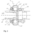
- the design of the Fig. 3 has a shorter overall axial length for the same joint 10, since the nut 20 partially disappears in the recess 16 of the inner hub 11.
- the first shaft 100 has a first region 101 with a first outer diameter and a front-side second region 102 with a second, smaller outer diameter.
- An external toothing 17 is seated on the first area 101 and an external thread is seated on the second area 102.
- the first shaft 100 and the inner hub 11 can thus be connected to one another for the torque transmission and axially braced against one another via the nut 20.
- the nut 20 has a first nut section 20 'and a second nut section 20 ", wherein the first nut section 20' has a larger outer diameter than the second nut section 20" and z. B. has a polygonal edge for twisting. Furthermore, the axial length of the second region 102 of the first shaft 100 is essentially equal to an axial length of the second nut section 20 ′′. The nut 20 is thus rotated against the first shaft 100 and the first nut section 20 ′ here abuts against the end face of the inner hub 11 on.
- the recess 16 of the inner hub 11 has a first nut receiving section 16 'and a second nut receiving section 16 "in the direction of its end face.
- the second nut receiving section 16" then lies behind, starting from the end face the first nut receiving portion 16 'and has a smaller inner diameter.
- the dimensions of the first nut receiving section 16 'and of the second nut receiving section 16 are matched to the dimensions of the two nut sections 20', 20" so that the nut 20 can be introduced into the recess 16 of the inner hub 11 with the section having the smaller outer diameter first . This shortens the overall axial length of the arrangement.
- the cover 62 is also designed like a cup here and has a depression in its base, preferably in the middle.
- the lowering rests in the inner recess of a stop area 34 'of the first adapter component 31.
- the stop area 34' is a type of narrowing of the inner area 34 of the annular first adapter component 31 inserted, it strikes against the stop area 34 'and the lowering closes the interior of the stop area 34'.
Landscapes
- Engineering & Computer Science (AREA)
- General Engineering & Computer Science (AREA)
- Mechanical Engineering (AREA)
- Sealing Devices (AREA)
Description
- Die vorliegende Erfindung betrifft eine Gelenkanordnung gemäß dem Oberbegriff des ersten Anspruchs.
- Eine gattungsgemäße Gelenkanordnung offenbart die
JP 2012-087820 A - Die Gelenkanordnung besteht zumindest aus einem Gelenk und aus weiteren Komponenten, die es erlauben, das Gelenk zwischen zwei Wellen zu fixieren. Das Gelenk lässt sich somit mit zwei Wellen verbinden. Das Gelenk und die Wellen sind dabei beispielsweise Teile eines Antriebsstrangs eines Kraftfahrzeugs. Über die Wellen wird hauptsächlich ein Drehmoment übertragen. Das Gelenk erlaubt beispielsweise die Kompensation von Winkeln zwischen den Wellen im Fahrzeug.
- Bei der Montage muss das Gelenk mit den beiden Wellen verbunden werden und es muss zudem noch Gelenkfett für das Gelenk eingebracht werden. Das Gelenkfett sollte entsprechend von einem möglichst abgeschlossenen Hohlraum der Gelenkanordnung umgeben sein. Gelenkfett ist dabei eine allgemeine Bezeichnung für eine Materie, die der Schmierung des Gelenks dient.
- Zwischen einem Deckel und einem Dichtbalg angeordnete Gelenke offenbaren die
DE 10 2006 062 822 B4 oder dieEP 2 264 327 B1 . - Eine abgeschlossene Anordnung mit zwei sich einander gegenüberliegenden Gelenken offenbaren die
US 3,714,797 und dieUS 4,185,475 . Dabei werden jeweils zwei Dichtbalge verwendet. - Eine Verbindung einer Welle mit einer Innennabe eines Gelenks vermittels einer Mutter offenbart die
DE 37 39 927 A1 . - Die der Erfindung zugrundeliegende Aufgabe besteht daher darin, eine Gelenkanordnung vorzuschlagen, die sich für die Montage unter Beachtung des Einbringens des Gelenkfetts eignet.
- Die Erfindung löst die Aufgabe durch eine Gelenkanordnung mit den Merkmalen des ersten Anspruchs. Die Mutter dient dabei der Fixierung an einer ersten Welle und die Adaptereinheit erlaubt die Verbindung mit einer zweiten Welle. Das Gelenk weist eine Innennabe, eine Außennabe, Kugeln und einen Käfig mit Aussparungen für die Kugeln auf. Es handelt sich somit um ein sogenanntes Gleichlaufgelenk. Die Innennabe weist eine Aussparung mit einer Innenverzahnung zur Aufnahme einer ersten Welle auf. Die erste Welle sollte daher vorzugsweise über eine zur Innenverzahnung passende Außenverzahnung verfügen. Die Mutter erlaubt die Fixierung der Innennabe, in der die erste Welle eingebracht ist, indem die Innennabe beispielsweise gegen ein Lager auf der ersten Welle oder z. B. gegen einen Absatz der ersten Welle verspannt wird. Um die Kugeln befindet sich ein Hohlraum der Gelenkanordnung. Dieser Hohlraum erlaubt beispielsweise die Einbringung des Gelenkfetts. Der Hohlraum ist dabei an zwei Stirnseiten von jeweils einer Dichtvorrichtung verschlossen. Die Stirnseiten liegen sich dabei vorzugsweise entlang einer Längsachse der Gelenkanordnung einander gegenüber. Die Stirnseiten sind weiterhin vorzugsweise der ersten Welle bzw. einer zweiten Welle zugewandt. Die Adaptereinheit weist eine erste Adapterkomponente und eine zweite Adapterkomponente auf. Die erste Adapterkomponente ist ringförmig ausgestaltet und weist eine Aussparung mit einem ersten Innendurchmesser auf. Die zweite Adapterkomponente ist ringförmig ausgestaltet. Die zweite Adapterkomponente weist eine erste Innenaussparung mit dem ersten Innendurchmesser und eine zweite Innenaussparung mit einem zweiten Innendurchmesser auf. Der erste Innendurchmesser ist größer als der zweite Innendurchmesser. Der erste Innendurchmesser ist zumindest gleich einem größten Außendurchmesser der Mutter.
- Eine Art der Montage der Gelenkanordnung kann somit beispielweise in folgenden Schritten bestehen:
- Die Gelenkanordnung wird mit einer ersten Welle verbunden, indem die Welle in die Innennabe eingebracht wird.
- Die Fixierung relativ zu der ersten Welle erfolgt über das Anziehen der Mutter.
- Hierauf wird das Gelenkfett in den Hohlraum eingebracht. Alternativ wurde es vorab in den Hohlraum eingebracht.
- Die zweite Dichtvorrichtung wird geschlossen.
- Die Verbindung mit der zweiten Welle erfolgt anschließend über die Adaptereinheit. Je nach Ausgestaltung der Adaptereinheit kann dies auch in mindestens zwei Schritten erfolgen.
- Die erste Dichtvorrichtung wird je nach Ausgestaltung vor der Verbindung mit der ersten Welle geschlossen oder dies geschieht danach.
- Die Adaptereinheit ist zumindest zweiteilig ausgeführt. Die Adaptereinheit weist somit eine erste Adapterkomponente und eine zweite Adapterkomponente auf. Die Zweiteiligkeit erlaubt beispielsweise einen Übergang zwischen unterschiedlichen Radien. Es kann beispielsweise das Gelenk mit einer Adapterkomponente und die zweite Welle mit der anderen Adapterkomponente verbunden werden. Bei der folgenden Montage werden dann erst die beiden Adapterkomponenten miteinander verbunden.
- Die erste Adapterkomponente ist ringförmig ausgestaltet und weist eine Aussparung mit einem ersten Innendurchmesser auf. Die zweite Adapterkomponente ist ebenfalls ringförmig ausgestaltet. Die zweite Adapterkomponente hat eine erste Innenaussparung mit dem ersten Innendurchmesser und eine zweite Innenaussparung mit einem zweiten Innendurchmesser. Dabei ist der erste Innendurchmesser größer als der zweite Innendurchmesser und der erste Innendurchmesser ist zumindest gleich einem größten Außendurchmesser der Mutter. Das Gelenk hat dabei in einer Ausgestaltung einen größeren Außendurchmesser als die zweite Welle.
- Wird also beispielsweise die erste Adapterkomponente mit dem Gelenk verbunden, so kann durch die Wahl des ersten Innendurchmessers und somit durch die Aussparung der ersten Adapterkomponente hindurch die Mutter noch festgezogen werden. Der zweite Innendurchmesser und die zweite Welle sind vorzugsweise passend zueinander abgestimmt, sodass z. B. die zweite Welle auf die zweite Adapterkomponente aufsteckbar ist.
- In einer Ausgestaltung ist vorgesehen, dass eine der Dichtvorrichtungen und zwar insbesondere die der ersten Welle zugeordnete - und daher im Folgenden als erste Dichtvorrichtung bezeichnete - Dichtvorrichtung durch einen Dichtbalg gebildet ist. Der Dichtbalg ist mit einer Außenseite der Innennabe und mit einem die Außennabe des Gelenks umfassenden Gehäuse verbunden. Der Dichtbalg der ersten Dichtvorrichtung erstreckt sich in allgemeiner Form von der Innennabe zu der Außennabe des Gelenks.
- In einer Ausgestaltung ist das Gehäuse, das auch die Außennabe umfasst, mit einer Außenseite der Adaptereinheit verbunden.
- In einer Ausgestaltung sind die'erste Adapterkomponente und die zweite Adapterkomponente für eine Übertragung eines Drehmoments ausgestaltet.
- Für die Drehmomentübertragung verfügen in einer Ausgestaltung die erste Adapterkomponente und die zweite Adapterkomponente jeweils über eine Hirth-Verzahnung an einer Stirnseite. Die Stirnseiten sind in einer Ausgestaltung weiterhin jeweils flanschartig ausgeführt, wobei z. B. mindestens eine Schraube durch die Flansche für die Fixierung der beiden Komponenten miteinander verwendet werden kann.
- In einer Ausgestaltung ist die zweite Adapterkomponente für eine Verbindung mit einer zweiten Welle ausgeführt. Dies geschieht beispielsweise durch eine Außenverzahnung auf der zweiten Adapterkomponente oder durch eine Innenverzahnung in einer Aussparung der zweiten Adapterkomponente.
- In einer Ausgestaltung verfügt die zweite Adapterkomponente über einen radial nach außen ragenden Flanschabschnitt. Gegen diesen Flanschabschnitt stößt bei der Montage beispielsweise die zweite Welle an.
- In den folgenden Ausgestaltungen wird die zweite Dichtvorrichtung beschrieben, die den Hohlraum in Richtung der Adaptereinheit und in Richtung der zweiten Welle verschließt.
- In einer Ausgestaltung ist die zweite Dichtvorrichtung durch ein Blechteil und einen Dichtbalg gebildet. Das Blechteil weist zumindest zwei Abschnitte auf. Zwischen der Innennabe und der Mutter befindet sich ein erster Abschnitt des Blechteils. Das Blechteil ist somit zwischen Innennabe und Mutter eingeklemmt. Angrenzend an den ersten Abschnitt des Blechteils befindet sich ein zweiter Abschnitt des Blechteils, der die Mutter radial umgibt. Das Umgeben ist dabei in einer Ausgestaltung nur teilweise gegeben bzw. beschränkt sich in einer Ausgestaltung darauf, dass der zweite Abschnitt sich radial nach außen erstreckt. Der Dichtbalg ist zwischen dem zweiten Abschnitt des Blechteils und einer Innenseite der Adaptereinheit und in einer Ausgestaltung einer Innenseite der ersten Adapterkomponente angeordnet.
- In einer Ausgestaltung ist somit ein - zweiter - Dichtbalg vorgesehen, der quasi von der ersten Adapterkomponente zu der Innennabe bzw. zu der Mutter geführt ist.
- In den weiteren Ausgestaltungen ist die zweite Dichtvorrichtung durch einen Deckel gebildet. Der Deckel ist dabei in einer Ausgestaltung becherförmig ausgeführt, wobei der Boden des Bechers dem Gelenk zugewandt ist.
- In einer Ausgestaltung befindet sich die seitliche Wandung des Bechers zumindest in der ersten Adapterkomponente und in einer weiteren Ausgestaltung teilweise auch in der zweiten Adapterkomponente.
- In einer Ausgestaltung ist der Deckel zumindest in eine Aussparung der Adaptereinheit und in einer weiteren Ausgestaltung insbesondere in eine Aussparung der ersten Adapterkomponente einbringbar. Diese Aussparung wird dann von dem Deckel im eingebrachten Zustand verschlossen. In einer Ausgestaltung ist ergänzend noch ein Dichtelement, z. B. ein O-Ring vorhanden.
- In einer weiteren Ausgestaltung ist der Deckel ebenfalls becherförmig ausgestaltet und verfügt über eine Vertiefung oder Absenkung im Boden. Eine solche Absenkung erlaubt es beispielsweise gezielt auf Gelenkeigenschaften, wie z. B. den maximalen Beugewinkel des Gelenks Einfluss zu nehmen.
- In einer Ausgestaltung weist die Aussparung der Innennabe einen ersten Mutteraufnahmeabschnitt und einen zweiten Mutteraufnahmeabschnitt auf. Die Mutter verfügt über einen ersten Mutterabschnitt und einen zweiten Mutterabschnitt, wobei der erste Mutterabschnitt einen größeren Außendurchmesser als der zweite Mutterabschnitt aufweist. Weiterhin ist der erste Mutteraufnahmeabschnitt zur Aufnahme des ersten Mutterabschnitts und der zweite Mutteraufnahmeabschnitt zur Aufnahme des zweiten Mutterabschnitts ausgestaltet. In dieser Ausgestaltung ist die Mutter somit in die Innennabe einbringbar. Somit wird bei der Montage beispielsweise die erste Welle in die Innennabe eingebracht und die Mutter wird mit der ersten Welle verschraubt. Durch den Abgleich der Radien kann dabei die Mutter in der Aussparung der Innennabe gleichsam verschwinden.
- Erfindungsgemäß verfügt die Gelenkanordnung über eine erste Welle. Dies ist somit die Welle, in deren Richtung der Hohlraum durch die erste Dichtvorrichtung verschlossen wird und die über die Mutter mit der Innennabe kontaktiert wird.
- Die erste Welle weist erfindungsgemäß einen ersten Bereich mit einem ersten Außendurchmesser und einem stirnseitigen zweiten Bereich mit einem zweiten Außendurchmesser auf. Der zweite Außendurchmesser ist kleiner als der erste Außendurchmesser. Der erste Bereich trägt eine Außenverzahnung, die passend zu der Innenverzahnung der Aussparung der Innennabe ausgestaltet ist. Der zweite Bereich weist ein Außengewinde passend zum Innengewinde der Mutter auf. Die Mutter weist einen ersten Mutterabschnitt und einen zweiten Mutterabschnitt auf, wobei der erste Mutterabschnitt einen größeren Außendurchmesser als der zweite Mutterabschnitt aufweist. Dabei ist eine axiale Länge des zweiten Bereichs im Wesentlichen gleich einer axialen Länge des zweiten Mutterabschnitts.
- In einer Ausgestaltung sind Mutter, Innennabe und erste Welle so ausgestaltet, dass der erste Mutterabschnitt gegen die Innennabe anstößt. In einer alternativen Ausgestaltung kann die Mutter in die Aussparung der Innennabe - z. B. bedingt durch die Längenverhältnisse und radialen Abmessungen - auch mit dem ersten Mutterabschnitt eingebracht werden.
- In einer Ausgestaltung weist die erste Adapterkomponente einen Anschlagbereich auf. Der Anschlagbereich hat dabei einen kleineren Innendurchmesser als die Aussparung der ersten Adapterkomponente mit dem ersten Innendurchmesser. Es besteht also ein Bereich einer Verengung in der Aussparung der ersten Adapterkomponente. Der Innendurchmesser des Anschlagbereichs ist zudem kleiner als ein größter Außendurchmesser des die zweite Dichtvorrichtung bildenden Deckels. Der Deckel wird somit durch den Anschlagbereich entgegen der Richtung zum Gelenk gehalten.
- In einer Ausgestaltung verfügt der Deckel über einen Becherboden, in dem sich eine Absenkung befindet. Der Außendurchmesser der Absenkung ist dabei gleich oder kleiner als der Innendurchmesser des Anschlagbereichs. Der Deckel sitzt also in dieser Ausgestaltung in der Aussparung des Anschlagbereichs.
- Im Einzelnen gibt es eine Vielzahl von Möglichkeiten, die erfindungsgemäße Mutter auszugestalten und weiterzubilden. Dazu wird verwiesen einerseits auf die dem Patentanspruch 1 nachgeordneten Patentansprüche, andererseits auf die folgende Beschreibung von Ausführungsbeispielen in Verbindung mit der Zeichnung. Es zeigen:
- Fig. 1
- einen Schnitt durch eine erste Ausgestaltung der Gelenkanordnung,
- Fig. 2
- einen Schnitt durch eine zweite Ausgestaltung der Gelenkanordnung,
- Fig. 3
- einen Schnitt durch eine dritte Ausgestaltung der Gelenkanordnung,
- Fig. 4
- einen Schnitt durch eine vierte Ausgestaltung der Gelenkanordnung und
- Fig. 5
- einen Schnitt durch eine fünfte Ausgestaltung der Gelenkanordnung.
- Die
Fig. 1 zeigt eine erste Ausgestaltung der Gelenkanordnung 1, die eine Verbindung des Gelenks 10 mit einer ersten Welle 100 und einer zweiten Welle 200 erlaubt. Die Gelenkanordnung 1 verfügt dafür über das Gelenk 10, die Mutter 20 und eine Adaptereinheit 30. - Das Gelenk 10 besteht aus einer Innennabe 11, einer Außennabe 12 und Kugeln 13 für die Drehmomentübertragung zwischen der Innennabe 11 und der Außennabe 12. Die Kugeln 13 sind in den Aussparungen 15 eines Käfigs 14 angeordnet.
- Die Kugeln 13 sind weiterhin von einem - hier nicht darstellten - Gelenkfett in einem Hohlraum 2 der Gelenkanordnung 1 befindlich. Der Hohlraum 2 ist dabei an den zwei Stirnseiten 3, 4 von jeweils einer Dichtvorrichtung 5, 6 verschlossen.
- Die Innennabe 11 verfügt über eine Aussparung 16 mit einer Innenverzahnung 17, in die die erste Welle 100 mit einer entsprechenden Außenverzahnung eingebracht wird. Die Innennabe 11 wird über die Mutter 20 in Richtung einer mit einem größeren Außendurchmesser als der Bereich mit der Außenverzahnung aufweisenden Bereich der ersten Welle 100 gepresst und somit axial entlang der Längsachse der Gelenkanordnung 1 fixiert.
- Die Dichtvorrichtung 5 an der Stirnseite 3 in Richtung der ersten Welle 100 wird dabei durch einen Dichtbalg 50 gebildet. Der Dichtbalg 50 ist dabei an einer Seite an einer Außenseite 18 der Innennabe 11 und an einer anderen Seite mit einem Gehäuse 7 verbunden.
- Das Gehäuse 7 umfasst die Außennabe 12 des Gelenks 10 und ist weiterhin mit der Adaptereinheit 30 - insbesondere mit der Außenseite 33 einer ersten Adapterkomponente 31 - verbunden. Das Gehäuse 7 dient somit auch der Drehmomentübertragung. Das Gehäuse 7 ist ergänzend noch im Bereich der Außennabe 12 von einer in Richtung der ersten Welle 100 sich erstreckenden Umfassungseinheit umgeben, wobei der eine Endbereich des Dichtbalgs 50 insbesondere zwischen der Umfassungseinheit und der Außenseite des Gehäuses 7 fixiert ist.
- Die zweite Dichtvorrichtung 6 an der zweiten Stirnseite 4 des Hohlraums 2 wird durch ein Blechteil 60 und einen weiteren Dichtbalg 61 gebildet. Das Blechteil 60 verfügt über einen Abschnitt, der zwischen der Innennabe 11 und der Mutter 20 fixiert ist. Ein weiterer Abschnitt des Blechteils 60 ragt radial nach außen und umfasst die Mutter 20. Der weitere Dichtbalg 61 ist mit dem die Mutter 20 umgebenden Abschnitt des Blechteils 60 und mit einer Innenseite der Adaptereinheit 30 verbunden. Durch das Blechteil 60 und den weiteren Dichtbalg 61 wird somit ein Abschluss des Hohlraums 2 geschaffen.
- Die Adaptereinheit 30 besteht aus einer ersten Adapterkomponente 31 und einer zweiten Adapterkomponente 32. Diese Aufteilung der Adaptereinheit 30 in zwei Komponenten 31, 32 mit unterschiedlichen Außendurchmessern erlaubt zum einen den Übergang auf einen kleineren Außendurchmesser der zweiten Welle 200 und zum anderen den Zugriff auf die Mutter 20 während der Montage, sodass die Mutter 20 angezogen werden kann.
- Die erste Adapterkomponente 31 und die zweite Adapterkomponente 32 verfügen jeweils über eine stirnseitige Hirth-Verzahnung zur Übertragung des Drehmoments.
- Die erste Adapterkomponente 31 ist ringförmig und hat eine Innenaussparung 34 mit einem ersten Innendurchmesser. Der erste Innendurchmesser ist dabei mindestens gleich einem größten Außendurchmesser der Mutter 20.
- Die zweite Adapterkomponente 32 hat eine erste Innenaussparung 35 mit dem ersten Innendurchmesser, die sich somit übergangslos an die Aussparung 34 der ersten Adapterkomponente 31 anschließt. Weiterhin verfügt die zweite Adapterkomponente 32 über eine zweite Innenaussparung 36 mit dem zweiten, kleineren Innendurchmesser.
- Die zweite Adapterkomponente 32 weist einen radial nach außen ragenden Flanschabschnitt 37 auf, an den die zweite Welle 200 herangeführt wird.
- Die zweite Welle 200 verfügt hier über eine Innenverzahnung, die passend zu der Außenverzahnung der zweiten Adapterkomponente 32 ausgestaltet ist. Zu sehen ist weiterhin, dass die flanschartigen Stirnseiten der zwei Adapterkomponenten 31, 32 durch Schrauben miteinander fixiert sind.
- Insgesamt fließt das Drehmoment über die erste Welle 100, durch das Gelenk 10 (also von der Innennabe 11, über die Kugeln 13 auf die Außennabe 12), in das Gehäuse 7, in die erste Adapterkomponente 31, in die zweite Adapterkomponente 32 und schließlich in die zweite Welle 200. Entsprechendes gilt für den umgekehrten Weg eines Drehmoments.
- In der Ausgestaltung der Gelenkanordnung 1 der
Fig. 2 ist die zweite Dichtvorrichtung 6 durch einen Deckel 62 gebildet. Die erste Dichtvorrichtung in Richtung der hier - zeichnerisch linken - Stirnseite 3 besteht weiterhin aus dem Dichtbalg 50. - Der Deckel 62 ist becherförmig ausgestaltet und der Boden des Bechers ist dem Gelenk 10 zugewandt. Der Außendurchmesser des Deckels 62 und der Innendurchmesser der Aussparung 34 sind so aufeinander abgeglichen, dass der Deckel 62 in die erste Adapterkomponente 31 einbringbar ist und diese verschließt. Somit ist auch der Hohlraum 2 in dieser Richtung verschlossen. Somit bilden das Gelenk 10 und die erste Adapterkomponente 31 eine Art von Einheit, in die z. B. das Gelenkfett eingebracht werden kann. Die Verbindung mit der zweiten Welle 200 erfolgt anschließend separat über die zweite Adapterkomponente 32 und deren Fixierung mit der ersten Adapterkomponente 31.
- Zu erkennen ist weiterhin, dass die erste Welle 100 axial entlang der Längsachse über die Innennabe 11 hinausragt und dass die Mutter 20 axial an die Innennabe 11 anschlägt. Das Gehäuse 7 umfasst die Außennabe des Gelenks 10 und ist mit der ersten Adapterkomponente 31 verbunden.
- In der Gelenkanordnung 1 der
Fig. 3 wird die zweite Dichtvorrichtung 6 ebenfalls durch einen Deckel 62 gebildet, der hier - wie in der Ausgestaltung derFig. 2 - zumindest in der ersten Adapterkomponente 31 befindlich ist. - Die Ausgestaltung der
Fig. 3 hat bei gleichem Gelenk 10 eine kürzere axiale Baulänge, da die Mutter 20 teilweise in der Aussparung 16 der Innennabe 11 verschwindet. - Die erste Welle 100 hat einen ersten Bereich 101 mit einem ersten Außendurchmesser und einem stirnseitigen zweiten Bereich 102 mit einem zweiten, kleineren Außendurchmesser. Auf dem ersten Bereich 101 sitzt eine Außenverzahnung 17 und auf dem zweiten Bereich 102 ein Außengewinde. Somit lassen sich die erste Welle 100 und die Innennabe 11 für die Drehmomentübertragung miteinander verbinden und über die Mutter 20 gegeneinander axial verspannen.
- Die Mutter 20 verfügt über einen ersten Mutterabschnitt 20' und einen zweiten Mutterabschnitt 20", wobei der erste Mutterabschnitt 20' einen größeren Außendurchmesser als der zweite Mutterabschnitt 20" aufweist und z. B. eine Mehrkantberandung zum Verdrehen aufweist. Weiterhin ist die axiale Länge des zweiten Bereichs 102 der ersten Welle 100 im Wesentlichen gleich einer axialen Länge des zweiten Mutterabschnitts 20". Die Mutter 20 wird somit gegen die erste Welle 100 gedreht und der erste Mutterabschnitt 20' stößt hier gegen die Stirnseite der Innennabe 11 an.
- In der Ausgestaltung der
Fig. 4 wird die Mutter 20 tiefer in die Innennabe 11 eingebracht und verschwindet damit in ihr. - Die Aussparung 16 der Innennabe 11 weist hierfür in Richtung ihrer Stirnseite einen ersten Mutteraufnahmeabschnitt 16' und einen zweiten Mutteraufnahmeabschnitt 16" auf. Der zweite Mutteraufnahmeabschnitt 16" liegt dann ausgehend von der Stirnseite hinter dem ersten Mutteraufnahmeabschnitt 16' und weist einen kleineren Innendurchmesser auf.
- Die Abmessungen des ersten Mutteraufnahmeabschnitts 16' und des zweiten Mutteraufnahmeabschnitts 16" sind dabei so mit den Abmessungen der zwei Mutternabschnitte 20', 20" abgeglichen, dass die Mutter 20 mit dem den kleineren Außendurchmesser aufweisenden Abschnitt voran in die Aussparung 16 der Innennabe 11 einbringbar ist. Damit verkürzt sich die axiale Baulänge der Anordnung.
- Weiterhin ist der Deckel 62 hier ebenfalls becherartig ausgestaltet und verfügt in seinem Boden - vorzugweise mittig - über eine Absenkung. Die Absenkung ruht dabei in der Innenaussparung eines Anschlagbereichs 34' der ersten Adapterkomponente 31. Der Anschlagbereich 34' ist dabei eine Art von Verengung des Innenbereichs 34 der ringförmigen ersten Adapterkomponente 31. Wird somit der Deckel 62 in die erste Adapterkomponente 31 in Richtung des Gelenks 10 eingeführt, so stößt er gegen den Anschlagbereich 34' und die Absenkung verschließt den Innenraum des Anschlagbereichs 34'.
- Bei der Ausgestaltung der Gelenkanordnung 1 der
Fig. 5 stößt die Mutter 20 mit dem ersten Mutterabschnitt 20' gegen die Stirnseite der Innennabe 11 an. Im Bereich der zweiten Dichtvorrichtung 6 ist auch ein O-Ring zwischen dem Deckel 62 und dem Anschlagsbereich 34' zu erkennen.
Claims (11)
- Gelenkanordnung (1) mit einem Gelenk (10) und einer Adaptereinheit (30), wobei das Gelenk (10) eine Innennabe (11), eine Außennabe (12), Kugeln (13) und einen Käfig (14) mit Aussparungen (15) für die Kugeln (13) aufweist, wobei die Innennabe (11) eine Aussparung (16) mit einer Innenverzahnung (17) zur Aufnahme einer ersten Welle (100) aufweist,
wobei sich um die Kugeln (13) ein Hohlraum (2) der Gelenkanordnung (1) befindet, wobei der Hohlraum (2) an zwei Stirnseiten (3, 4) von jeweils einer Dichtvorrichtung (5, 6) verschlossen ist,
wobei die Adaptereinheit (30) eine erste Adapterkomponente (31) und eine zweite Adapterkomponente (32) aufweist,
wobei die erste Adapterkomponente (31) ringförmig ausgestaltet ist und eine Aussparung (34) mit einem ersten Innendurchmesser aufweist,
wobei die zweite Adapterkomponente (32) ringförmig ausgestaltet ist, wobei die zweite Adapterkomponente (32) eine erste Innenaussparung (35) mit dem ersten Innendurchmesser und eine zweite Innenaussparung (36) mit einem zweiten Innendurchmesser aufweist,
wobei der erste Innendurchmesser größer als der zweite Innendurchmesser ist, und
wobei eine erste Welle (100) vorhanden ist,
dadurch gekennzeichnet,
dass die Gelenkanordnung (1) eine Mutter (20) aufweist,
dass der erste Innendurchmesser zumindest gleich einem größten Außendurchmesser der Mutter (20) ist,
dass die erste Welle (100) einen ersten Bereich (101) mit einem ersten Außendurchmesser und einem stirnseitigen zweiten Bereich (102) mit einem zweiten Außendurchmesser aufweist,
dass der zweite Außendurchmesser kleiner als der erste Außendurchmesser ist, dass der erste Bereich (101) eine Außenverzahnung trägt, die passend zu der Innenverzahnung (17) der Aussparung (16) der Innennabe (11) ausgestaltet ist, dass der zweite Bereich (102) ein Außengewinde passend zum Innengewinde der Mutter (20) aufweist,
dass die Mutter (20) einen ersten Mutterabschnitt (20') und einen zweiten Mutterabschnitt (20") aufweist,
dass der erste Mutterabschnitt (20') einen größeren Außendurchmesser als der zweite Mutterabschnitt (20") aufweist, und
dass eine axiale Länge des zweiten Bereichs (102) gleich einer axialen Länge des zweiten Mutterabschnitts (20") ist. - Gelenkanordnung (1) nach Anspruch 1,
wobei die erste Adapterkomponente (31) und die zweite Adapterkomponente (32) für eine Übertragung eines Drehmoments ausgestaltet sind. - Gelenkanordnung (1) nach Anspruch 2,
wobei die erste Adapterkomponente (31) und die zweite Adapterkomponente (32) jeweils eine Hirth-Verzahnung an einer Stirnseite aufweisen. - Gelenkanordnung (1) nach einem der Ansprüche 1 bis 3,
wobei die zweite Adapterkomponente (32) für eine Verbindung mit einer zweiten Welle (200) ausgestaltet ist. - Gelenkanordnung (1) nach einem der Ansprüche 1 bis 4,
wobei die zweite Adapterkomponente (32) einen radial nach außen ragenden Flanschabschnitt (37) aufweist. - Gelenkanordnung (1) nach einem der Ansprüche 1 bis 5,
wobei die erste Adapterkomponente (31) einen Anschlagbereich (34') aufweist, wobei der Anschlagbereich (34') einen kleineren Innendurchmesser als die Aussparung (34) mit dem ersten Innendurchmesser aufweist, und
wobei der Innendurchmesser des Anschlagbereichs (34') kleiner als ein größter Außendurchmesser des die zweite Dichtvorrichtung (6) bildenden Deckels (62) ist. - Gelenkanordnung (1) nach einem der Ansprüche 1 bis 6,
wobei eine erste Dichtvorrichtung (5) durch einen Dichtbalg (50) gebildet ist, und wobei der Dichtbalg (50) mit einer Außenseite (18) der Innennabe (11) und mit einem die Außennabe (12) des Gelenks (10) umfassenden Gehäuse (7) verbunden ist. - Gelenkanordnung (1) nach Anspruch 7,
wobei das Gehäuse (7) mit einer Außenseite (33) der Adaptereinheit (30) verbunden ist. - Gelenkanordnung (1) nach einem der Ansprüche 1 bis 8,
wobei eine zweite Dichtvorrichtung (6) durch ein Blechteil (60) und einen Dichtbalg (61) gebildet ist,
wobei sich zwischen der Innennabe (11) und der Mutter (20) ein erster Abschnitt des Blechteils (60) befindet,
wobei angrenzend an den ersten Abschnitt des Blechteils (60) ein zweiter Abschnitt des Blechteils (60) derartig ausgestaltet ist, dass der zweite Abschnitt die Mutter (20) radial umgibt, und
wobei der Dichtbalg (61) zwischen dem zweiten Abschnitt des Blechteils (60) und einer Innenseite der Adaptereinheit (30) angeordnet ist. - Gelenkanordnung (1) nach einem der Ansprüche 1 bis 8,
wobei eine zweite Dichtvorrichtung (6) durch einen Deckel (62) gebildet ist, und wobei der Deckel (62) zumindest in eine Aussparung (34) der Adaptereinheit (30) einbringbar ist und diese verschließt. - Gelenkanordnung (1) nach einem der Ansprüche 1 bis 10,
wobei die Aussparung (16) der Innennabe (11) einen ersten Mutteraufnahmeabschnitt (16') und einen zweiten Mutteraufnahmeabschnitt (16") aufweist, wobei die Mutter (20) einen ersten Mutterabschnitt (20') und einen zweiten Mutterabschnitt (20") aufweist,
wobei der erste Mutterabschnitt (20') einen größeren Außendurchmesser als der zweite Mutterabschnitt (20") aufweist,
wobei der erste Mutteraufnahmeabschnitt (16') zur Aufnahme des ersten Mutterabschnitts (20') und der zweite Mutteraufnahmeabschnitt (16") zur Aufnahme des zweiten Mutterabschnitts (20") ausgestaltet ist.
Applications Claiming Priority (1)
| Application Number | Priority Date | Filing Date | Title |
|---|---|---|---|
| DE102017010421.2A DE102017010421A1 (de) | 2017-11-10 | 2017-11-10 | Gelenkanordnung |
Publications (2)
| Publication Number | Publication Date |
|---|---|
| EP3483463A1 EP3483463A1 (de) | 2019-05-15 |
| EP3483463B1 true EP3483463B1 (de) | 2021-07-21 |
Family
ID=64048656
Family Applications (1)
| Application Number | Title | Priority Date | Filing Date |
|---|---|---|---|
| EP18000842.7A Active EP3483463B1 (de) | 2017-11-10 | 2018-10-29 | Gelenkanordnung |
Country Status (3)
| Country | Link |
|---|---|
| US (1) | US11105379B2 (de) |
| EP (1) | EP3483463B1 (de) |
| DE (1) | DE102017010421A1 (de) |
Family Cites Families (10)
| Publication number | Priority date | Publication date | Assignee | Title |
|---|---|---|---|---|
| GB637718A (en) * | 1946-05-16 | 1950-05-24 | William Cull | Improvements in and relating to torque transmitting universal joints |
| CA930562A (en) * | 1969-12-11 | 1973-07-24 | G. Fisher Leslie | Universal joints |
| GB1429176A (en) * | 1972-07-07 | 1976-03-24 | Gkn Transmissions Ltd | Universal joints |
| ES467112A1 (es) * | 1977-04-07 | 1978-11-01 | Gelenkwellenbau Gmbh | Una junta homocinetica. |
| DE2810942C3 (de) * | 1978-03-14 | 1981-04-23 | Uni-Cardan Ag, 5200 Siegburg | Dichtungsanordnung |
| DE3739927A1 (de) * | 1987-11-25 | 1989-06-08 | Man Nutzfahrzeuge Gmbh | Gleichlaufgelenk |
| DE10342497A1 (de) * | 2003-09-12 | 2005-04-21 | Shaft Form Engineering Gmbh | Anbindungssystem für eine Welle an ein Gelenk |
| CN101368599A (zh) * | 2005-02-17 | 2009-02-18 | 轴成型工程有限公司 | 驱动轴和用于驱动轴的同步活节 |
| US20060185124A1 (en) * | 2005-02-18 | 2006-08-24 | Kozlowski Keith A | Joint assembly with centering flange |
| JP5623232B2 (ja) * | 2010-10-15 | 2014-11-12 | Ntn株式会社 | 等速自在継手用連結構造 |
-
2017
- 2017-11-10 DE DE102017010421.2A patent/DE102017010421A1/de not_active Withdrawn
-
2018
- 2018-10-29 EP EP18000842.7A patent/EP3483463B1/de active Active
- 2018-11-07 US US16/183,403 patent/US11105379B2/en active Active
Also Published As
| Publication number | Publication date |
|---|---|
| DE102017010421A1 (de) | 2019-05-16 |
| US20190145466A1 (en) | 2019-05-16 |
| US11105379B2 (en) | 2021-08-31 |
| EP3483463A1 (de) | 2019-05-15 |
Similar Documents
| Publication | Publication Date | Title |
|---|---|---|
| DE102004048079C5 (de) | Verbindungsanordnung zwischen einem Wellenzapfen und einem Gleichlaufdrehgelenk mit Verschraubungshülse | |
| EP3327303B1 (de) | Verbindungsanordnung zum verbinden einer welle mit einem bauteil | |
| DE102004009477B4 (de) | Verbindungsanordnung zwischen einem Wellenzapfen und einem Drehgelenk | |
| WO2008148373A1 (de) | Vorrichtung zur drehfesten verbindung eines zapfens eines getriebes mit einem gelenkkörper eines antriebsgelenks einer antriebswelle | |
| WO2009059597A1 (de) | Doppelkupplungsgetriebe und verfahren zur montage eines doppelkupplungsgetriebes | |
| DE112015001171B4 (de) | Gelenkwelle und in der Gelenkwelle verwendetes Gleichlaufgelenk | |
| DE102006006441A1 (de) | Gelenkanordnung mit Dichtmitteln und Vorrichtung zur Montage der Dichtmittel | |
| EP3190302B1 (de) | Abdichtanordnung für einen längenausgleich einer gelenkwelle und gelenkwelle | |
| EP3334949B1 (de) | Verbindungsanordnung eines getriebes in einer struktur | |
| WO2001063135A1 (de) | Baueinheit zur lagerung und antriebsverbindung eines rades | |
| EP3483463A1 (de) | Gelenkanordnung | |
| DE102007005849B4 (de) | Verbindungsanordnung zwischen einem Gleichlaufdrehgelenk und einem Wellenbauteil | |
| LU101812B1 (de) | Ankoppelvorrichtung und Verfahren zum drehmomentübertragenden Ankoppeln einer Antriebsvorrichtung an ein Getriebe | |
| EP3728900A1 (de) | Verzahnungsanordnung | |
| EP3318774A1 (de) | Verbindungsanordnung zum verbinden einer welle mit einem bauteil | |
| DE102006034035B4 (de) | Radnaben-Drehgelenk-Anordnung mit Axialsicherung der Radnabe durch gesicherten Sicherungsring | |
| EP3519226B1 (de) | Achsgetriebe für ein kraftfahrzeug | |
| EP1741942A2 (de) | Lagerung einer Welle eines Kegelrades | |
| EP3985275B1 (de) | Gleichlaufgelenk | |
| WO2015149779A1 (de) | Dichtelement für eine kupplungsglocke | |
| LU500882B1 (de) | Ankoppelvorrichtung zum drehmomentübertragenden Ankoppeln eines Antriebsmotors an ein Getriebe | |
| DE10008182B4 (de) | Baueinheit zur Lagerung und Antriebsverbindung eines Rades | |
| DE102011104058B4 (de) | Verbindungsanordnung zwischen einer Gelenkwelle und einem Getriebe | |
| DE102013218192B4 (de) | Gleichlaufgelenk zur Befestigung an einem Getriebeflansch | |
| DE102008031865A1 (de) | Kupplungseinrichtung mit einer Welle und einem Nabenteil |
Legal Events
| Date | Code | Title | Description |
|---|---|---|---|
| PUAI | Public reference made under article 153(3) epc to a published international application that has entered the european phase |
Free format text: ORIGINAL CODE: 0009012 |
|
| STAA | Information on the status of an ep patent application or granted ep patent |
Free format text: STATUS: REQUEST FOR EXAMINATION WAS MADE |
|
| 17P | Request for examination filed |
Effective date: 20181108 |
|
| AK | Designated contracting states |
Kind code of ref document: A1 Designated state(s): AL AT BE BG CH CY CZ DE DK EE ES FI FR GB GR HR HU IE IS IT LI LT LU LV MC MK MT NL NO PL PT RO RS SE SI SK SM TR |
|
| AX | Request for extension of the european patent |
Extension state: BA ME |
|
| GRAP | Despatch of communication of intention to grant a patent |
Free format text: ORIGINAL CODE: EPIDOSNIGR1 |
|
| STAA | Information on the status of an ep patent application or granted ep patent |
Free format text: STATUS: GRANT OF PATENT IS INTENDED |
|
| RIC1 | Information provided on ipc code assigned before grant |
Ipc: F16D 3/223 20110101AFI20210210BHEP |
|
| INTG | Intention to grant announced |
Effective date: 20210304 |
|
| GRAS | Grant fee paid |
Free format text: ORIGINAL CODE: EPIDOSNIGR3 |
|
| GRAA | (expected) grant |
Free format text: ORIGINAL CODE: 0009210 |
|
| STAA | Information on the status of an ep patent application or granted ep patent |
Free format text: STATUS: THE PATENT HAS BEEN GRANTED |
|
| AK | Designated contracting states |
Kind code of ref document: B1 Designated state(s): AL AT BE BG CH CY CZ DE DK EE ES FI FR GB GR HR HU IE IS IT LI LT LU LV MC MK MT NL NO PL PT RO RS SE SI SK SM TR |
|
| REG | Reference to a national code |
Ref country code: GB Ref legal event code: FG4D Free format text: NOT ENGLISH |
|
| REG | Reference to a national code |
Ref country code: CH Ref legal event code: EP |
|
| REG | Reference to a national code |
Ref country code: DE Ref legal event code: R096 Ref document number: 502018006165 Country of ref document: DE |
|
| REG | Reference to a national code |
Ref country code: AT Ref legal event code: REF Ref document number: 1412861 Country of ref document: AT Kind code of ref document: T Effective date: 20210815 |
|
| REG | Reference to a national code |
Ref country code: IE Ref legal event code: FG4D Free format text: LANGUAGE OF EP DOCUMENT: GERMAN |
|
| REG | Reference to a national code |
Ref country code: LT Ref legal event code: MG9D |
|
| REG | Reference to a national code |
Ref country code: NL Ref legal event code: MP Effective date: 20210721 |
|
| PG25 | Lapsed in a contracting state [announced via postgrant information from national office to epo] |
Ref country code: RS Free format text: LAPSE BECAUSE OF FAILURE TO SUBMIT A TRANSLATION OF THE DESCRIPTION OR TO PAY THE FEE WITHIN THE PRESCRIBED TIME-LIMIT Effective date: 20210721 Ref country code: SE Free format text: LAPSE BECAUSE OF FAILURE TO SUBMIT A TRANSLATION OF THE DESCRIPTION OR TO PAY THE FEE WITHIN THE PRESCRIBED TIME-LIMIT Effective date: 20210721 Ref country code: HR Free format text: LAPSE BECAUSE OF FAILURE TO SUBMIT A TRANSLATION OF THE DESCRIPTION OR TO PAY THE FEE WITHIN THE PRESCRIBED TIME-LIMIT Effective date: 20210721 Ref country code: FI Free format text: LAPSE BECAUSE OF FAILURE TO SUBMIT A TRANSLATION OF THE DESCRIPTION OR TO PAY THE FEE WITHIN THE PRESCRIBED TIME-LIMIT Effective date: 20210721 Ref country code: ES Free format text: LAPSE BECAUSE OF FAILURE TO SUBMIT A TRANSLATION OF THE DESCRIPTION OR TO PAY THE FEE WITHIN THE PRESCRIBED TIME-LIMIT Effective date: 20210721 Ref country code: BG Free format text: LAPSE BECAUSE OF FAILURE TO SUBMIT A TRANSLATION OF THE DESCRIPTION OR TO PAY THE FEE WITHIN THE PRESCRIBED TIME-LIMIT Effective date: 20211021 Ref country code: LT Free format text: LAPSE BECAUSE OF FAILURE TO SUBMIT A TRANSLATION OF THE DESCRIPTION OR TO PAY THE FEE WITHIN THE PRESCRIBED TIME-LIMIT Effective date: 20210721 Ref country code: PT Free format text: LAPSE BECAUSE OF FAILURE TO SUBMIT A TRANSLATION OF THE DESCRIPTION OR TO PAY THE FEE WITHIN THE PRESCRIBED TIME-LIMIT Effective date: 20211122 Ref country code: NO Free format text: LAPSE BECAUSE OF FAILURE TO SUBMIT A TRANSLATION OF THE DESCRIPTION OR TO PAY THE FEE WITHIN THE PRESCRIBED TIME-LIMIT Effective date: 20211021 Ref country code: NL Free format text: LAPSE BECAUSE OF FAILURE TO SUBMIT A TRANSLATION OF THE DESCRIPTION OR TO PAY THE FEE WITHIN THE PRESCRIBED TIME-LIMIT Effective date: 20210721 |
|
| PG25 | Lapsed in a contracting state [announced via postgrant information from national office to epo] |
Ref country code: PL Free format text: LAPSE BECAUSE OF FAILURE TO SUBMIT A TRANSLATION OF THE DESCRIPTION OR TO PAY THE FEE WITHIN THE PRESCRIBED TIME-LIMIT Effective date: 20210721 Ref country code: LV Free format text: LAPSE BECAUSE OF FAILURE TO SUBMIT A TRANSLATION OF THE DESCRIPTION OR TO PAY THE FEE WITHIN THE PRESCRIBED TIME-LIMIT Effective date: 20210721 Ref country code: GR Free format text: LAPSE BECAUSE OF FAILURE TO SUBMIT A TRANSLATION OF THE DESCRIPTION OR TO PAY THE FEE WITHIN THE PRESCRIBED TIME-LIMIT Effective date: 20211022 |
|
| REG | Reference to a national code |
Ref country code: DE Ref legal event code: R097 Ref document number: 502018006165 Country of ref document: DE |
|
| PG25 | Lapsed in a contracting state [announced via postgrant information from national office to epo] |
Ref country code: DK Free format text: LAPSE BECAUSE OF FAILURE TO SUBMIT A TRANSLATION OF THE DESCRIPTION OR TO PAY THE FEE WITHIN THE PRESCRIBED TIME-LIMIT Effective date: 20210721 |
|
| PLBE | No opposition filed within time limit |
Free format text: ORIGINAL CODE: 0009261 |
|
| STAA | Information on the status of an ep patent application or granted ep patent |
Free format text: STATUS: NO OPPOSITION FILED WITHIN TIME LIMIT |
|
| REG | Reference to a national code |
Ref country code: CH Ref legal event code: PL |
|
| PG25 | Lapsed in a contracting state [announced via postgrant information from national office to epo] |
Ref country code: SM Free format text: LAPSE BECAUSE OF FAILURE TO SUBMIT A TRANSLATION OF THE DESCRIPTION OR TO PAY THE FEE WITHIN THE PRESCRIBED TIME-LIMIT Effective date: 20210721 Ref country code: SK Free format text: LAPSE BECAUSE OF FAILURE TO SUBMIT A TRANSLATION OF THE DESCRIPTION OR TO PAY THE FEE WITHIN THE PRESCRIBED TIME-LIMIT Effective date: 20210721 Ref country code: RO Free format text: LAPSE BECAUSE OF FAILURE TO SUBMIT A TRANSLATION OF THE DESCRIPTION OR TO PAY THE FEE WITHIN THE PRESCRIBED TIME-LIMIT Effective date: 20210721 Ref country code: EE Free format text: LAPSE BECAUSE OF FAILURE TO SUBMIT A TRANSLATION OF THE DESCRIPTION OR TO PAY THE FEE WITHIN THE PRESCRIBED TIME-LIMIT Effective date: 20210721 Ref country code: CZ Free format text: LAPSE BECAUSE OF FAILURE TO SUBMIT A TRANSLATION OF THE DESCRIPTION OR TO PAY THE FEE WITHIN THE PRESCRIBED TIME-LIMIT Effective date: 20210721 Ref country code: AL Free format text: LAPSE BECAUSE OF FAILURE TO SUBMIT A TRANSLATION OF THE DESCRIPTION OR TO PAY THE FEE WITHIN THE PRESCRIBED TIME-LIMIT Effective date: 20210721 |
|
| REG | Reference to a national code |
Ref country code: BE Ref legal event code: MM Effective date: 20211031 |
|
| 26N | No opposition filed |
Effective date: 20220422 |
|
| PG25 | Lapsed in a contracting state [announced via postgrant information from national office to epo] |
Ref country code: MC Free format text: LAPSE BECAUSE OF FAILURE TO SUBMIT A TRANSLATION OF THE DESCRIPTION OR TO PAY THE FEE WITHIN THE PRESCRIBED TIME-LIMIT Effective date: 20210721 |
|
| PG25 | Lapsed in a contracting state [announced via postgrant information from national office to epo] |
Ref country code: LU Free format text: LAPSE BECAUSE OF NON-PAYMENT OF DUE FEES Effective date: 20211029 Ref country code: IT Free format text: LAPSE BECAUSE OF FAILURE TO SUBMIT A TRANSLATION OF THE DESCRIPTION OR TO PAY THE FEE WITHIN THE PRESCRIBED TIME-LIMIT Effective date: 20210721 Ref country code: BE Free format text: LAPSE BECAUSE OF NON-PAYMENT OF DUE FEES Effective date: 20211031 |
|
| PG25 | Lapsed in a contracting state [announced via postgrant information from national office to epo] |
Ref country code: LI Free format text: LAPSE BECAUSE OF NON-PAYMENT OF DUE FEES Effective date: 20211031 Ref country code: CH Free format text: LAPSE BECAUSE OF NON-PAYMENT OF DUE FEES Effective date: 20211031 |
|
| PG25 | Lapsed in a contracting state [announced via postgrant information from national office to epo] |
Ref country code: IE Free format text: LAPSE BECAUSE OF NON-PAYMENT OF DUE FEES Effective date: 20211029 |
|
| PGFP | Annual fee paid to national office [announced via postgrant information from national office to epo] |
Ref country code: FR Payment date: 20221024 Year of fee payment: 5 |
|
| PGFP | Annual fee paid to national office [announced via postgrant information from national office to epo] |
Ref country code: GB Payment date: 20221018 Year of fee payment: 5 |
|
| PG25 | Lapsed in a contracting state [announced via postgrant information from national office to epo] |
Ref country code: CY Free format text: LAPSE BECAUSE OF FAILURE TO SUBMIT A TRANSLATION OF THE DESCRIPTION OR TO PAY THE FEE WITHIN THE PRESCRIBED TIME-LIMIT Effective date: 20210721 |
|
| PG25 | Lapsed in a contracting state [announced via postgrant information from national office to epo] |
Ref country code: HU Free format text: LAPSE BECAUSE OF FAILURE TO SUBMIT A TRANSLATION OF THE DESCRIPTION OR TO PAY THE FEE WITHIN THE PRESCRIBED TIME-LIMIT; INVALID AB INITIO Effective date: 20181029 |
|
| PG25 | Lapsed in a contracting state [announced via postgrant information from national office to epo] |
Ref country code: MK Free format text: LAPSE BECAUSE OF FAILURE TO SUBMIT A TRANSLATION OF THE DESCRIPTION OR TO PAY THE FEE WITHIN THE PRESCRIBED TIME-LIMIT Effective date: 20210721 |
|
| GBPC | Gb: european patent ceased through non-payment of renewal fee |
Effective date: 20231029 |
|
| PG25 | Lapsed in a contracting state [announced via postgrant information from national office to epo] |
Ref country code: TR Free format text: LAPSE BECAUSE OF FAILURE TO SUBMIT A TRANSLATION OF THE DESCRIPTION OR TO PAY THE FEE WITHIN THE PRESCRIBED TIME-LIMIT Effective date: 20210721 |
|
| PG25 | Lapsed in a contracting state [announced via postgrant information from national office to epo] |
Ref country code: GB Free format text: LAPSE BECAUSE OF NON-PAYMENT OF DUE FEES Effective date: 20231029 |
|
| PG25 | Lapsed in a contracting state [announced via postgrant information from national office to epo] |
Ref country code: GB Free format text: LAPSE BECAUSE OF NON-PAYMENT OF DUE FEES Effective date: 20231029 Ref country code: FR Free format text: LAPSE BECAUSE OF NON-PAYMENT OF DUE FEES Effective date: 20231031 |
|
| PG25 | Lapsed in a contracting state [announced via postgrant information from national office to epo] |
Ref country code: MT Free format text: LAPSE BECAUSE OF FAILURE TO SUBMIT A TRANSLATION OF THE DESCRIPTION OR TO PAY THE FEE WITHIN THE PRESCRIBED TIME-LIMIT Effective date: 20210721 |
|
| REG | Reference to a national code |
Ref country code: AT Ref legal event code: MM01 Ref document number: 1412861 Country of ref document: AT Kind code of ref document: T Effective date: 20231029 |
|
| PG25 | Lapsed in a contracting state [announced via postgrant information from national office to epo] |
Ref country code: AT Free format text: LAPSE BECAUSE OF NON-PAYMENT OF DUE FEES Effective date: 20231029 |
|
| PG25 | Lapsed in a contracting state [announced via postgrant information from national office to epo] |
Ref country code: AT Free format text: LAPSE BECAUSE OF NON-PAYMENT OF DUE FEES Effective date: 20231029 |
|
| PGFP | Annual fee paid to national office [announced via postgrant information from national office to epo] |
Ref country code: DE Payment date: 20251021 Year of fee payment: 8 |
|
| PGFP | Annual fee paid to national office [announced via postgrant information from national office to epo] |
Ref country code: AT Payment date: 20260410 Year of fee payment: 5 |