EP3483448A1 - Vakuumpumpe mit ballastgasventil - Google Patents
Vakuumpumpe mit ballastgasventil Download PDFInfo
- Publication number
- EP3483448A1 EP3483448A1 EP17201444.1A EP17201444A EP3483448A1 EP 3483448 A1 EP3483448 A1 EP 3483448A1 EP 17201444 A EP17201444 A EP 17201444A EP 3483448 A1 EP3483448 A1 EP 3483448A1
- Authority
- EP
- European Patent Office
- Prior art keywords
- pump
- vacuum pump
- valve
- rotary body
- channel
- Prior art date
- Legal status (The legal status is an assumption and is not a legal conclusion. Google has not performed a legal analysis and makes no representation as to the accuracy of the status listed.)
- Granted
Links
Images


Classifications
-
- F—MECHANICAL ENGINEERING; LIGHTING; HEATING; WEAPONS; BLASTING
- F04—POSITIVE - DISPLACEMENT MACHINES FOR LIQUIDS; PUMPS FOR LIQUIDS OR ELASTIC FLUIDS
- F04C—ROTARY-PISTON, OR OSCILLATING-PISTON, POSITIVE-DISPLACEMENT MACHINES FOR LIQUIDS; ROTARY-PISTON, OR OSCILLATING-PISTON, POSITIVE-DISPLACEMENT PUMPS
- F04C25/00—Adaptations of pumps for special use of pumps for elastic fluids
- F04C25/02—Adaptations of pumps for special use of pumps for elastic fluids for producing high vacuum
-
- F—MECHANICAL ENGINEERING; LIGHTING; HEATING; WEAPONS; BLASTING
- F04—POSITIVE - DISPLACEMENT MACHINES FOR LIQUIDS; PUMPS FOR LIQUIDS OR ELASTIC FLUIDS
- F04B—POSITIVE-DISPLACEMENT MACHINES FOR LIQUIDS; PUMPS
- F04B37/00—Pumps having pertinent characteristics not provided for in, or of interest apart from, groups F04B25/00 - F04B35/00
- F04B37/10—Pumps having pertinent characteristics not provided for in, or of interest apart from, groups F04B25/00 - F04B35/00 for special use
- F04B37/14—Pumps having pertinent characteristics not provided for in, or of interest apart from, groups F04B25/00 - F04B35/00 for special use to obtain high vacuum
-
- F—MECHANICAL ENGINEERING; LIGHTING; HEATING; WEAPONS; BLASTING
- F04—POSITIVE - DISPLACEMENT MACHINES FOR LIQUIDS; PUMPS FOR LIQUIDS OR ELASTIC FLUIDS
- F04B—POSITIVE-DISPLACEMENT MACHINES FOR LIQUIDS; PUMPS
- F04B39/00—Component parts, details, or accessories, of pumps or pumping systems specially adapted for elastic fluids, not otherwise provided for in, or of interest apart from, groups F04B25/00 - F04B37/00
- F04B39/10—Adaptations or arrangements of distribution members
-
- F—MECHANICAL ENGINEERING; LIGHTING; HEATING; WEAPONS; BLASTING
- F04—POSITIVE - DISPLACEMENT MACHINES FOR LIQUIDS; PUMPS FOR LIQUIDS OR ELASTIC FLUIDS
- F04B—POSITIVE-DISPLACEMENT MACHINES FOR LIQUIDS; PUMPS
- F04B39/00—Component parts, details, or accessories, of pumps or pumping systems specially adapted for elastic fluids, not otherwise provided for in, or of interest apart from, groups F04B25/00 - F04B37/00
- F04B39/12—Casings; Cylinders; Cylinder heads; Fluid connections
- F04B39/121—Casings
-
- F—MECHANICAL ENGINEERING; LIGHTING; HEATING; WEAPONS; BLASTING
- F04—POSITIVE - DISPLACEMENT MACHINES FOR LIQUIDS; PUMPS FOR LIQUIDS OR ELASTIC FLUIDS
- F04B—POSITIVE-DISPLACEMENT MACHINES FOR LIQUIDS; PUMPS
- F04B39/00—Component parts, details, or accessories, of pumps or pumping systems specially adapted for elastic fluids, not otherwise provided for in, or of interest apart from, groups F04B25/00 - F04B37/00
- F04B39/12—Casings; Cylinders; Cylinder heads; Fluid connections
- F04B39/123—Fluid connections
-
- F—MECHANICAL ENGINEERING; LIGHTING; HEATING; WEAPONS; BLASTING
- F04—POSITIVE - DISPLACEMENT MACHINES FOR LIQUIDS; PUMPS FOR LIQUIDS OR ELASTIC FLUIDS
- F04C—ROTARY-PISTON, OR OSCILLATING-PISTON, POSITIVE-DISPLACEMENT MACHINES FOR LIQUIDS; ROTARY-PISTON, OR OSCILLATING-PISTON, POSITIVE-DISPLACEMENT PUMPS
- F04C28/00—Control of, monitoring of, or safety arrangements for, pumps or pumping installations specially adapted for elastic fluids
- F04C28/24—Control of, monitoring of, or safety arrangements for, pumps or pumping installations specially adapted for elastic fluids characterised by using valves controlling pressure or flow rate, e.g. discharge valves or unloading valves
-
- F—MECHANICAL ENGINEERING; LIGHTING; HEATING; WEAPONS; BLASTING
- F04—POSITIVE - DISPLACEMENT MACHINES FOR LIQUIDS; PUMPS FOR LIQUIDS OR ELASTIC FLUIDS
- F04C—ROTARY-PISTON, OR OSCILLATING-PISTON, POSITIVE-DISPLACEMENT MACHINES FOR LIQUIDS; ROTARY-PISTON, OR OSCILLATING-PISTON, POSITIVE-DISPLACEMENT PUMPS
- F04C29/00—Component parts, details or accessories of pumps or pumping installations, not provided for in groups F04C18/00 - F04C28/00
- F04C29/12—Arrangements for admission or discharge of the working fluid, e.g. constructional features of the inlet or outlet
- F04C29/124—Arrangements for admission or discharge of the working fluid, e.g. constructional features of the inlet or outlet with inlet and outlet valves specially adapted for rotary or oscillating piston pumps
-
- F—MECHANICAL ENGINEERING; LIGHTING; HEATING; WEAPONS; BLASTING
- F04—POSITIVE - DISPLACEMENT MACHINES FOR LIQUIDS; PUMPS FOR LIQUIDS OR ELASTIC FLUIDS
- F04C—ROTARY-PISTON, OR OSCILLATING-PISTON, POSITIVE-DISPLACEMENT MACHINES FOR LIQUIDS; ROTARY-PISTON, OR OSCILLATING-PISTON, POSITIVE-DISPLACEMENT PUMPS
- F04C2220/00—Application
- F04C2220/50—Pumps with means for introducing gas under pressure for ballasting
Definitions
- the present invention relates to a vacuum pump with a pump body, the inside of which defines a pumping space and on the outside of which a valve for controlling the supply of a ballast gas is arranged in the pumping space, the valve having an inlet opening and an outlet opening.
- Vacuum pumps of the type mentioned are basically known and are used, in particular, as pre-pumps for generating a backing vacuum in an outlet region of a high-vacuum pump.
- additional gas generally referred to herein as ballast gas, as a sweep gas, purge gas or purge gas into the pump body.
- ballast gas in the form of an inert barrier gas is introduced into the pump body to protect sensitive components of the vacuum pump.
- the ballast gas can also be used for cooling, for example, at a made by a shift of the operating point heating of the vacuum pump.
- So-called towing gas is introduced in order to be able to pump particularly light gases such as hydrogen or helium better.
- Towing gas may also be used to transport unwanted accumulations, eg condensation of liquid or solid deposits within the pumping system, in the direction of ejection of the vacuum pump.
- ballast gas can be introduced as purge gas to prevent condensation of, in particular corrosive, gases in the pump chamber.
- ballast gas comes for this application, for example, nitrogen in question.
- ballast gas in the pump body is usually controlled by a valve, the inlet opening is connected by means of a connecting hose with a ballast gas container and the outlet opening is in communication with the pump body.
- known ballast gas valves have only two settings, namely "valve open” and “valve closed”. A change in the amount of ballast gas supplied per unit time is not possible in the known valves.
- the invention is therefore an object of the invention to provide a vacuum pump of the type mentioned, which makes it possible to change the amount of ballast gas supplied per unit time in a simple and cost-effective manner.
- a vacuum pump with the features of claim 1 and in particular in that a first and a second channel are formed in the pump body, wherein the input of each channel faces the valve and the output of each channel opens into the pump chamber, the Valve between a first and a second open position is adjustable and the outlet opening is aligned in the first open position with the input of the first channel and in the second open position with the input of the second channel.
- ballast gas can be introduced either through the first channel or through the second channel in the pump chamber.
- ballast gas can be introduced either through the first channel or through the second channel in the pump chamber.
- the channels With appropriate design of the channels thereby a multi-stage supply of ballast gas in the pump room is possible.
- a position of the valve is conceivable in which the outlet opening of the valve is aligned neither with the input of the first channel nor with the input of the second channel, but the inputs of both channels are rather closed, so that no ballast gas is introduced into the pump chamber ,
- the vacuum pump according to the invention is in particular a backing pump.
- the vacuum pump according to the invention in the form of a single or multi-stage scroll, diaphragm, rotary valve, rotary piston, reciprocating, screw, claw or as Roots pump can be formed.
- the first and second channels have different lengths in order to be able to introduce the ballast gas into different regions of the pump chamber.
- This makes it possible, for example, to introduce ballast gas optionally in a central region or an edge region of the pump chamber.
- the channels open into different pressure zones of the pump chamber, in particular into an inner region with a higher gas density and into a region located further out with a lower gas density.
- the outputs of the first and second channels have different cross-sectional areas. Since the amount of ballast gas that can be introduced into the pumping space per unit of time from the cross-sectional area results of the respective channel output and the prevailing pressure difference between the channel outlet and the outlet opening of the valve, can be introduced by the selection of the channel different amounts of ballast gas in the pump chamber.
- At least partial sections of the first and second channels have different cross-sectional areas. Since the amount of ballast gas which can be introduced into the pump space per unit of time results from the cross-sectional area and the section length of the respective channel and the prevailing pressure difference between the channel exit and the outlet opening of the valve, the selection of the channel allows different quantities of ballast gas to be introduced into the pumping space.
- At least one first and second channel have at least one channel section which is different in length and / or cross-sectional area and terminate in a common outlet opening, preferably with at least one shared channel section. Since the amount of ballast gas which can be introduced into the pump space per unit of time results from the cross-sectional area and the section length of the respective channel and the prevailing pressure difference between the channel exit and the outlet opening of the valve, the selection of the channel allows different quantities of ballast gas to be introduced into the pumping space.
- more than two, preferably three or more channels and corresponding further positions of the valve are provided to allow a further grading of the amount of ballast gas.
- a first channel in an inner region of the pump chamber with a higher gas density and two other channels with different cross-sectional areas and / or channel lengths in a common outlet opening in a more remote area of the pump chamber with a lower gas density open which can be introduced different amounts of ballast gas at different locations of the pump chamber.
- a maximum dimension of the output of one or each channel is equal to or less than a width of a separator that separates two regions of the pumping space and moves across the or each outlet during operation of the vacuum pump. This prevents ballast gas from undesirably flowing from one to the other when the separator moves across the outlet during operation of the vacuum pump. In other words, a "gas short circuit" is avoided.
- the valve may in principle be designed to be displaceable on the pump body, i. the outlet opening of the valve is aligned by a linear movement with the inputs of the channels.
- the valve comprises a rotary body which is rotatably mounted on the pump body, wherein a longitudinal axis of a valve bore and an axis of rotation of the rotary body are arranged offset parallel to each other.
- the selection of the first or second channel for the supply of a ballast gas can be designed in a particularly simple manner by the valve being adjustable by rotation of the rotary body between the first and the second open position.
- the valve arranged in the rotary body offset from the axis of rotation describes a partial circular path which comprises the inputs of the first and second channels.
- a closure or zero position of the valve can be provided at a corresponding angle of rotation of the rotary body in which the inputs of both channels are closed at the same time and the supply of ballast gas is suppressed in the pump chamber.
- the inputs of the channels are each enclosed by a sealing element, in particular a sealing ring.
- the sealing elements prevent that supplied ballast gas can escape uncontrollably and / or ambient air flow into the pump chamber and can contaminate the pre-vacuum of the vacuum pump. The same applies to the reverse flow path, because pumped gas can be contaminated and must not be discharged into this environment under any circumstances, even for example in case of overpressure of the pump chamber to the environment.
- the sealing elements serve as spacers between the underside of the rotary body and the pump body, whereby a friction-loaded contact preferably exclusively between the rotary body and the sealing elements, but not between the rotary body and the pump body. This reduces the friction between these mutually movable components, which reduces their wear, allows longer maintenance intervals and contributes to a more cost-effective operation of the vacuum pump.
- At least three sealing elements are provided, which are distributed around the axis of rotation of the rotary body around, in particular at least approximately symmetrically arranged.
- the symmetrical arrangement counteracts a tilting of the rotary body and ensures that the underside of the rotary body and the inputs of the channels comprehensive level of the pump body are always aligned at least approximately parallel, which counteracts undesirable abrasion and contributes to an optimal sealing effect of the sealing elements.
- At least one or more sealing elements may also be blind, i. without channel, designed and arranged to produce sufficient symmetry with the other sealing elements.
- the rotary body is provided on its underside facing the pump body with a dry lubricant.
- a dry lubricant for example PTFE or MoS2 is suitable. Dry lubricants of this type are not only particularly resistant, but produce also very little abrasion, for example, could get into the pump body and contaminate the pre-vacuum.
- the sealing elements are each provided with a dry lubricant at least on their side facing the rotary body.
- the dry lubricant may be applied as a bonded coating on the sealing elements.
- the density elements may for example be enclosed by a PTFE lubricating varnish and be in contact with a PTFE-coated surface of the rotating body.
- the rotary body has a tensioning device in order to bias the rotary body, in particular along its axis of rotation, against the pump body.
- the clamping device By means of the clamping device, the rotary body is pressed against the sealing rings and the pump body.
- the biasing force acting on the rotary body is chosen so that it ensures a maximum tightness of the valve and on the other hand a minimum effort is required to operate the valve, i. to select one of the open positions or the closure or zero position by rotation of the rotary body. Too much force would also cause increased abrasion and wear of the dry lubricant.
- the pump body forms a part-circular guide slot.
- the guide slot can have recesses at the positions corresponding to the first and second open positions. It is also conceivable that an additional recess is formed, which corresponds to the position of the closure or zero position.
- the rotary body is provided with a guide element which protrudes from the pump body facing the underside of the rotary body and is guided in the guide slot of the pump body.
- the guide element makes it easier to find the open positions or the closure or zero position during a rotation of the rotary body.
- the guide element contributes to a stabilization of the plane-parallel arrangement of the rotary body and the surface of the pump body.
- the guide element on a spring-loaded ball body, which engages in the guide slot.
- the size of the spherical body is ideally adapted to the size of the depressions in the guide slot.
- the spherical body is designed to be vertically displaceable on the underside of the guide element facing the guide slot, wherein a vertical displacement of the spherical body in the direction of the rotary body takes place counter to the restoring force of a spring element which is arranged in the guide element.
- angles of rotation of the rotary body which do not correspond to an open position or the closure or zero position, the ball body is pressed by the guide slot in the direction of the rotary body and tensioned the spring element.
- the restoring force of the spring element drives the spherical body into the recess, i. the ball body snaps into the recess.
- labels are advantageously mounted on an outer side of the pump body, indicating the correct rotational angle of the rotary body for the first open position, the second open position and / or the closure or zero position.
- the rotary body may have a non-circular cross-section, which may be formed in particular direction-indicating. Conceivable here are for example ansatzweise arrow-shaped formations in which the arrowhead indicates the current angle of rotation. Also, oval or other non-circular configurations of the rotating body, which in particular can be easily grab and easily operated manually, are possible, with additional markings on the top of the rotating body can serve as a direction indicator.
- Fig. 1 is an embodiment of a ballast gas valve 12 of a vacuum pump 10 according to the invention, shown here in the form of a scroll pump.
- the ballast gas valve 12 is formed on a hood 14 which on a pump body 16 (see Fig. 2 ) and has display elements 18 on its outside.
- the hood 14 may be molded from plastic and made, for example, by an injection molding process.
- the hood 14 In the region of a ballast gas inlet, the hood 14 has a circular recess 20 for a rotary body 22 for controlling the supply of ballast gas.
- the rotary body 22 is provided with a along a rotational axis D of the rotary body 22 extending receiving bore 34 for receiving a clamping device which secures the rotary body 22 to the pump body 16 and biases along the axis of rotation D against a flat connection surface 17 of the pump body 16.
- the tensioning device comprises a screw 28 which engages in a threaded bore 30 of the pump body 16 in order to rotatably secure the rotary body 22 to the pump body 16 about the axis of rotation D.
- the screw 28 forms a shoulder 28 a, which is seated in the maximum screwed state of the screw 28 on the connection surface 17 of the pump body 16 and thereby limits the biasing force acting on the rotary body 22, which is held between the screw head 28 b and the pump body 16.
- the tensioning device can also comprise a spring element arranged in the receiving bore 34 and acting along the axis of rotation D, against the restoring force of which the screw 28 is tightened.
- the rotary body 22 is formed in two pieces.
- a first, the pump body 16 facing away from the section forms a head piece 24 and may be made of a plastic or metal material.
- a second, the pump body 16 facing portion is formed in the form of a sliding plate 26, which may also be made of a plastic or metal material.
- An underside of the sliding disk 26 facing the pump body 16 is coated with a sliding layer of a dry lubricant such as PTFE or MoS2.
- the head piece 24 and the sliding disk 26 of the rotary body 22 are connected to each other by means of several, in the present embodiment, three, connecting elements 32 which are guided by parallel to the rotation axis D bores 36 in the head piece 24 and in the sliding disk 26.
- the connecting elements 32 are formed as Allen screws, which extend through the head piece 24 and are screwed into threaded holes 30 of the sliding plate 26.
- a further extending parallel to the rotation axis D bore 38 for receiving a guide member 40 is further formed, which extends through the sliding plate 26 and extends partially into the head piece 24.
- the guide element 40 is designed as a metal pin and has a spring-loaded ball 42 at its end facing the pump body 16.
- the ball 42 is slidably mounted in the longitudinal direction of the guide member 40 and can be at least partially pushed into the guide member 40 against the restoring force of a spring element, not shown.
- a valve bore 44 is formed in the rotary body 22, which defines an inlet opening 46 and an outlet opening 48.
- a connecting piece 50 is inserted into the valve bore 44, via which a ballast gas can be introduced into the valve bore 44.
- a sealing ring 52 is provided for sealing the connecting piece 50 with respect to the rotary body 22.
- the valve bore 44 extends through both the head piece 24 and the sliding disk 26 of the rotary body 22 and is composed of a plurality of bore portions together.
- An outgoing from the inlet opening 46, formed in the head piece 24 first bore portion has a smaller cross-sectional area than an adjoining, also located in the head piece 24 second bore portion.
- the second bore portion communicates with a third bore portion extending through the sliding washer 26, which opens into the outlet opening 48.
- valve bore 44 forms in the transition from the first bore section to the second bore section a valve seat 54 for a displaceably mounted in the second bore portion valve body 56, which by a spring element 57, here in the form of a helical compression spring, is pressed against the valve seat 54.
- the valve seat 54 and the valve body 56 form in this way a check valve 53, which prevents a backflow of both the introduced through the connecting piece 50 in the valve bore 44 ballast gas as well as the pumped by the vacuum pump medium.
- two channels 58 are formed in the pump body 16, each having a channel 60 and a channel outlet, not shown.
- the channel exits of the channels 58 open into different areas of the pump chamber, for example in areas separated by a spiral wall regions of a scroll pump.
- the channel exits may have different cross-sectional areas, so that 58 different amounts of ballast gas per unit time can be introduced into the pump chamber through the channels.
- a smaller amount of ballast gas per unit time can be fed into the pump chamber than through the second channel 58.
- the maximum dimensions of the channel outputs are the same or smaller than the width of a separator, not shown, separating two portions of the pump space from each other and moving during operation of the vacuum pump 10 via one or both channel exits, such as a spiral wall of the scroll pump.
- the channels 58 may be both orthogonal to the pad 17 of the pump body 16 as well as at any oblique angle to reach a predetermined, remotely located outlet opening 48 or a channel starting with the outlet opening 48 in the pump body 16 and thus a connection between the channel inlet 60 and outlet opening 48 create.
- the cross-sectional area of the outlet opening 48 of the valve bore 44 is matched to the cross-sectional area of the channel inlets 60 and is at least similar or equal, preferably smaller, than the cross-sectional areas of the channel inlets 60.
- the channel inlets 60 are enclosed by sealing rings 62 located in corresponding grooves 64 of the pump body 16 are included.
- the sealing rings 62 form a support surface for the rotary body 22, that is, the sealing body 22 is only in contact with the sealing rings 62, but not with the surface of the pump body 16th
- the sealing rings 62 are provided with a dry lubricant.
- the sealing rings 62 may be coated with a PTFE varnish.
- dry lubricants such as PTFE or MoS2 reduces the contamination of the pump chamber with lubricant particles that could pass through the channels 58 in the pump chamber.
- dry lubricants compared to lubricants such as grease or oil, dry lubricants have less wear and allow a lower-maintenance and lower-cost operation of the vacuum pump 10.
- dry lubricants do not evaporate or creep as easily as liquid lubricants that can flow away, evaporate or evaporate. This especially concerns the operation of the pump with high housing temperatures, which can reduce the viscosity of the liquid lubricant and volatilize components with low boiling points.
- a combination of dry and liquid lubricants, for example PTFE and an oil, can advantageously lead to a further increased service life and lubricity, above all to an increased run-flat safety in the event that one of the two components unexpectedly or unexpectedly fails due to unintended use or volatilizes.
- At least one additional sealing ring 66 is provided which forms a blind element without connection to a channel 58.
- a bearing surface is provided which extends plane-parallel to the surface of the pump body 16 and holds the rotary body 22 during rotation in a corresponding plane-parallel position.
- a part-circular guide slot 68 is formed on the surface of the pump body 16, in which engages the attached to the rotary body 22 guide member 40, as shown in the perspective view in FIG Fig. 4 is shown.
- the guide slot 68 has three recesses 70, in which the spring-loaded ball 42 of the guide member 40 respectively engages when the rotary body 22 in a first open position, in which the outlet opening 48 is aligned with the entrance of the first channel 58, in a second open position , in which the outlet opening 48 is aligned with the inlet of the second channel 58, and in a closed position, in which the outlet opening 48 with neither the entrance of the first channel 58, nor with the entrance of the second Channel 58 is aligned.
- These locking positions facilitate the finding and setting of the correct angle of rotation of the rotary body 22 for the open positions and for the closed position.
- adjustment aid 14 display elements 18, for example in the form of labels, attached to the hood 14, which indicate the correct rotational angle to be set for the open positions and the closed position.
- To indicate the current angle of rotation of the rotary body 22 is formed non-circular, in particular, the head piece 24 of the rotary body 22 in the illustrated embodiment, a rudimentary arrow-shaped basic shape, wherein the arrowhead points in the direction of the current angle of rotation.
- oval or other non-circular configurations of the rotary body 22 are possible, which are easy to grip and easy to operate manually. It is also conceivable that 22 additional markings are attached to the rotary body, which indicate the current angle of rotation of the rotary body 22.
- the connecting piece 50 is connected by means of a connection line, not shown, with a ballast gas container also not shown and the rotary body 22 is rotated to the desired open position until the guide member 40 engages in the corresponding recess 70 of the guide slot 68. Due to the ballast gas flowing into the valve bore 44, the valve body 56 is lifted off the valve seat 54 so that the ballast gas can flow through the channel inlet 60 into the selected channel 58 and through the outlet of the respective channel 58 into the pump chamber of the vacuum pump 10.
- the invention does not have such a seal above, it should be understood that another seal member may be disposed on the pad 17 such that it closes off the outlet port 48 in occlusion or zero position of the ballast gas valve 12 so that it will seal Position at existing pressure differences no ballast gas can escape through the gap formed between the sliding disk 26 and channel entrance 60 into the environment or vice versa ambient air can enter the ballast gas line.
- the invention does not have such a guide slot 68 above, such may also be continuous without interruption, or that the recesses 70 may be arranged directly on the terminal surface 17 on a face concentric with the axis of rotation D without guide slot 68 can, so that the spring-loaded ball 42 can engage in this. Accordingly, the rotary body 22 can be rotated arbitrarily times in any direction about the rotation axis D, since there is no geometric limit.
Landscapes
- Engineering & Computer Science (AREA)
- Mechanical Engineering (AREA)
- General Engineering & Computer Science (AREA)
- Physics & Mathematics (AREA)
- Fluid Mechanics (AREA)
- Applications Or Details Of Rotary Compressors (AREA)
- Compressors, Vaccum Pumps And Other Relevant Systems (AREA)
- Sliding Valves (AREA)
Abstract
Description
- Die vorliegende Erfindung betrifft eine Vakuumpumpe mit einem Pumpenkörper, dessen Innenseite einen Pumpraum begrenzt und an dessen Außenseite ein Ventil zur Steuerung der Zufuhr eines Ballastgases in den Pumpraum angeordnet ist, wobei das Ventil eine Einlassöffnung und eine Auslassöffnung aufweist.
- Vakuumpumpen der genannten Art sind grundsätzlich bekannt und finden insbesondere als Vorpumpen zur Erzeugung eines Vorvakuums in einem Auslassbereich einer Hochvakuumpumpe Anwendung. Im Betrieb ist es unter bestimmten Umständen erforderlich, zusätzliches Gas, hier allgemein als Ballastgas bezeichnet, als Schleppgas, Spülgas oder Sperrgas in den Pumpenkörper einzuführen.
- Beispielsweise wird bei der Förderung von korrosiven Gasen Ballastgas in der Form eines inerten Sperrgases in den Pumpenkörper eingeführt, um empfindliche Bauteile der Vakuumpumpe zu schützen. Das Ballastgas kann auch zur Kühlung eingesetzt werden, beispielsweise bei einer durch eine Verschiebung des Betriebspunkts erfolgten Erwärmung der Vakuumpumpe. Sogenanntes Schleppgas wird eingeleitet, um besonders leichte Gase wie Wasserstoff oder Helium besser pumpen zu können. Schleppgas kann auch genutzt werden, um unerwünschte Ansammlungen, z.B. Kondensation von flüssigen oder Ablagerungen von festen Stoffen innerhalb des Pumpsystems in Richtung eines Ausstoßes der Vakuumpumpe zu transportieren. Nach dem Abschalten der Vakuumpumpe kann Ballastgas als Spülgas eingebracht werden, um eine Kondensation von, insbesondere korrosiven, Gasen im Pumpraum zu verhindern. Als Ballastgas kommt für diese Anwendung beispielweise Stickstoff infrage.
- Weitere Anwendungsbereiche betreffen die Verdünnung eines gepumpten gasförmigen Mediums ("Passivbeigabe"), um beispielsweise eine zündfähige Gaskonzentration zu vermeiden, die durch eine Kompression des Mediums während des Pumpvorgangs in verschiedenen Stellen im Pumpsystem entstehen kann. Dagegen wird das gepumpte Medium bei einer "Aktivbeigabe" zu einer unschädlicheren Art verändert, wobei beispielsweise durch Beigabe von geeigneten Reaktionspartnern bzw. Katalysatoren korrosive oder auf eine andere Art schädliche Bestandteile des gepumpten Mediums ausgefällt und entfernt werden können.
- Die Zufuhr von Ballastgas in den Pumpenkörper wird üblicherweise durch ein Ventil gesteuert, dessen Einlassöffnung mittels eines Verbindungsschlauches mit einem Ballastgasbehälter verbunden ist und dessen Auslassöffnung mit dem Pumpenkörper in Verbindung steht. Bekannte Ballastgasventile weisen jedoch nur zwei Einstellungen auf, nämlich "Ventil geöffnet" und "Ventil geschlossen". Eine Veränderung der Menge des pro Zeiteinheit zugeführten Ballastgases ist bei den bekannten Ventilen nicht möglich.
- Der Erfindung liegt daher die Aufgabe zugrunde, eine Vakuumpumpe der eingangs genannten Art zu schaffen, die es ermöglicht, die Menge des pro Zeiteinheit zugeführten Ballastgases in einfacher und kostengünstiger Weise zu verändern.
- Die Aufgabe wird durch eine Vakuumpumpe mit den Merkmalen des Anspruchs 1 und insbesondere dadurch gelöst, dass ein erster und ein zweiter Kanal in dem Pumpenkörper ausgebildet sind, wobei der Eingang jedes Kanals dem Ventil zugewandt ist und der Ausgang jedes Kanals in den Pumpraum mündet, das Ventil zwischen einer ersten und einer zweiten Öffnungsstellung verstellbar ist und die Auslassöffnung in der ersten Öffnungsstellung mit dem Eingang des ersten Kanals und in der zweiten Öffnungsstellung mit dem Eingang des zweiten Kanals ausgerichtet ist.
- Je nach Ausrichtung der Auslassöffnung des Ventils kann Ballastgas wahlweise durch den ersten Kanal oder durch den zweiten Kanal in den Pumpraum eingeleitet werden. Bei entsprechender Ausbildung der Kanäle ist hierdurch eine mehrstufige Zufuhr von Ballastgas in den Pumpraum möglich. Außerdem ist eine Stellung des Ventils denkbar, in welcher die Auslassöffnung des Ventils weder mit dem Eingang des ersten Kanals noch mit dem Eingang des zweiten Kanals ausgerichtet ist, sondern die Eingänge beider Kanäle vielmehr verschlossen sind, so dass gar kein Ballastgas in den Pumpraum eingeleitet wird.
- Bei der erfindungsgemäßen Vakuumpumpe handelt es sich insbesondere um eine Vorpumpe. Beispielsweise kann die erfindungsgemäße Vakuumpumpe in Form einer ein- oder mehrstufigen Scroll-, Membran-, Drehschieber-, Drehkolben-, Hubkolben-, Schrauben-, Klauen- oder auch als Wälzkolbenpumpe ausgebildet sein.
- Vorteilhafte Ausbildungen der Erfindung sind den Unteransprüchen, der Beschreibung und der Zeichnung zu entnehmen.
- Gemäß einer Ausführungsform weisen der erste und zweite Kanal unterschiedliche Längen auf, um das Ballastgas in unterschiedliche Bereiche des Pumpraums einführen zu können. Hierdurch ist es beispielsweise möglich, Ballastgas wahlweise in einen Zentralbereich oder einen Randbereich des Pumpraums einzuleiten. Insbesondere kann es vorgesehen sein, dass die Kanäle in unterschiedliche Druckzonen des Pumpraums münden, insbesondere in einen inneren Bereich mit einer höheren Gasdichte und in einen weiter außen gelegenen Bereich mit einer geringeren Gasdichte.
- Gemäß einer weiteren Ausführungsform weisen die Ausgänge des ersten und zweiten Kanals unterschiedliche Querschnittsflächen auf. Da sich die pro Zeiteinheit in den Pumpraum einführbare Ballastgasmenge aus der Querschnittsfläche des jeweiligen Kanalausgangs und der vorherrschenden Druckdifferenz zwischen dem Kanalausgang und der Auslassöffnung des Ventils ergibt, lassen sich durch die Auswahl des Kanals unterschiedliche Ballastgasmengen in den Pumpraum einleiten.
- Gemäß einer weiteren Ausführungsform weisen zumindest Teilabschnitte des ersten und zweiten Kanals unterschiedliche Querschnittsflächen auf. Da sich die pro Zeiteinheit in den Pumpraum einführbare Ballastgasmenge aus der Querschnittsfläche und der Abschnittslänge des jeweiligen Kanals und der vorherrschenden Druckdifferenz zwischen dem Kanalausgang und der Auslassöffnung des Ventils ergibt, lassen sich durch die Auswahl des Kanals unterschiedliche Ballastgasmengen in den Pumpraum einleiten.
- Gemäß einer weiteren Ausführungsform weisen zumindest ein erster und zweiter Kanal zumindest einen in der Länge und/oder Querschnittsfläche unterschiedlichen Kanalabschnitt auf und münden in einer gemeinsamen Auslassöffnung, bevorzugt mit zumindest einem gemeinsam genutzten Kanalabschnitt. Da sich die pro Zeiteinheit in den Pumpraum einführbare Ballastgasmenge aus der Querschnittsfläche und der Abschnittslänge des jeweiligen Kanals und der vorherrschenden Druckdifferenz zwischen dem Kanalausgang und der Auslassöffnung des Ventils ergibt, lassen sich durch die Auswahl des Kanals unterschiedliche Ballastgasmengen in den Pumpraum einleiten.
- Gemäß einer weiteren Ausführungsform sind mehr als zwei, bevorzugt drei oder mehr Kanäle und entsprechende weitere Stellungen des Ventils vorgesehen, um eine weitere Abstufung der Ballastgasmenge zu ermöglichen. Durch Kombination der vorgenannten Varianten können z.B. ein erster Kanal in einen inneren Bereich des Pumpraums mit einer höheren Gasdichte und zwei weitere Kanäle mit unterschiedlichen Querschnittsflächen und/oder Kanallängen in eine gemeinsame Auslassöffnung in einen weiter außen gelegenen Bereich des Pumpraums mit einer geringeren Gasdichte münden, wodurch sich verschiedene Ballastgasmengen an unterschiedlichen Orten des Pumpraums einleiten lassen.
- Vorteilhafterweise ist eine maximale Abmessung des Ausgangs eines oder jedes Kanals gleich oder kleiner als eine Breite eines Trennelements, das zwei Bereiche des Pumpraums voneinander trennt und sich im Betrieb der Vakuumpumpe über den oder jeden Ausgang hinweg bewegt. Dadurch wird verhindert, dass Ballastgas unerwünscht von dem einem in den anderen Bereich strömen kann, wenn sich das Trennelement im Betrieb der Vakuumpumpe über den Ausgang hinweg bewegt. Mit anderen Worten wird ein "Gaskurzschluss" vermieden.
- Zur Auswahl der jeweiligen Öffnungsstellung kann das Ventil grundsätzlich verschiebbar an dem Pumpenkörper ausgebildet sein, d.h. die Auslassöffnung des Ventils wird durch eine lineare Bewegung mit den Eingängen der Kanäle ausgerichtet. Bevorzugt umfasst das Ventil jedoch einen Drehkörper, der an dem Pumpenkörper drehbar gelagert ist, wobei eine Längsachse einer Ventilbohrung und eine Drehachse des Drehkörpers parallel versetzt zueinander angeordnet sind.
- Besonders einfach lässt sich die Auswahl des ersten oder zweiten Kanals für die Zufuhr eines Ballastgases dadurch gestalten, dass das Ventil durch Drehung des Drehkörpers zwischen der ersten und der zweiten Öffnungsstellung verstellbar ist. Mit anderen Worten beschreibt das im Drehkörper versetzt zur Drehachse angeordnete Ventil eine Teilkreisbahn, die die Eingänge des ersten und zweiten Kanals umfasst. Zusätzlich zu den beiden Öffnungsstellungen kann bei einem entsprechenden Drehwinkel des Drehkörpers auch eine Verschluss- oder Nullstellung des Ventils vorgesehen sein, in der die Eingänge beider Kanäle gleichzeitig verschlossen sind und die Zufuhr von Ballastgas in den Pumpraum unterbunden ist.
- Vorteilhafterweise sind die Eingänge der Kanäle jeweils von einem Dichtelement, insbesondere einem Dichtring, umschlossen. Die Dichtelemente verhindern, dass zugeführtes Ballastgas unkontrolliert entweichen kann und/oder Umgebungsluft in den Pumpraum strömen und das Vorvakuum der Vakuumpumpe kontaminieren kann. Selbiges gilt auch für den umgekehrten Strömungsweg, denn gepumptes Gas kann kontaminiert sein und darf dann unter keinen Umständen, auch z.B. bei Überdruck des Pumpraums gegenüber der Umgebung, nicht in diese Umgebung abgegeben werden. Außerdem dienen die Dichtelemente als Abstandshalter zwischen der Unterseite des Drehkörpers und dem Pumpenkörper, wodurch ein reibungsbelasteter Kontakt bevorzugt ausschließlich zwischen dem Drehkörper und den Dichtelementen, nicht aber zwischen dem Drehkörper und dem Pumpenkörper besteht. Hierdurch vermindert sich die Reibung zwischen diesen gegeneinander bewegbaren Bauteilen, was deren Abnutzung reduziert, längere Wartungsintervalle ermöglicht und zu einem kostengünstigeren Betrieb der Vakuumpumpe beiträgt.
- Gemäß einer weiteren Ausführungsform sind wenigstens drei Dichtelemente vorgesehen, welche um die Drehachse des Drehkörpers herum verteilt, insbesondere zumindest annähernd symmetrisch, angeordnet sind. Die symmetrische Anordnung wirkt einer Verkippung des Drehkörpers entgegen und gewährleistet, dass die Unterseite des Drehkörpers und eine die Eingänge der Kanäle umfassende Ebene des Pumpenkörpers stets zumindest annähernd parallel ausgerichtet sind, was unerwünschtem Abrieb entgegenwirkt und zu einer optimalen Dichtwirkung der Dichtelemente beiträgt. Nicht jedes Dichtelement muss einen Kanal umschließen und abdichten, mindestens ein oder mehrere Dichtelemente können auch blind, d.h. ohne Kanal, ausgeführt und angeordnet sein, um eine ausreichende Symmetrie mit den anderen Dichtelementen herzustellen.
- Gemäß einer bevorzugten Ausführungsform ist der Drehkörper an seiner dem Pumpenkörper zugewandten Unterseite mit einem Trockenschmiermittel versehen. Als Trockenschmiermittel kommt beispielsweise PTFE oder MoS2 infrage. Trockenschmiermittel dieser Art sind nicht nur besonders beständig, sondern erzeugen auch besonders wenig Abrieb, der beispielsweise in den Pumpenkörper gelangen und das Vorvakuum kontaminieren könnte.
- Alternativ oder zusätzlich sind die Dichteelemente zumindest auf ihrer dem Drehkörper zugewandten Seite jeweils mit einem Trockenschmiermittel versehen. Insbesondere kann das Trockenschmiermittel als Gleitlack auf die Dichtelemente aufgebracht sein. Für eine komplett trockene Ausbildung des Ventils können die Dichteelemente beispielsweise von einem PTFE Gleitlack umschlossen sein und mit einer PTFE beschichteten Oberfläche des Drehkörpers in Verbindung stehen.
- Gemäß einer weiteren Ausführungsform weist der Drehkörper eine Spannvorrichtung auf, um den Drehkörper, insbesondere entlang seiner Drehachse, gegen den Pumpenkörper vorzuspannen. Mittels der Spannvorrichtung wird der Drehkörper gegen die Dichtringe und den Pumpenkörper gepresst. Dabei ist die auf den Drehkörper wirkende Vorspannkraft so gewählt, dass sie eine maximale Dichtigkeit des Ventils gewährleistet und andererseits eine minimale Kraftanstrengung erforderlich ist, um das Ventil zu betätigen, d.h. durch Verdrehung des Drehkörpers eine der Öffnungsstellungen oder die Verschluss- oder Nullstellung auszuwählen. Eine zu große Kraftwirkung würde überdies einen erhöhten Abrieb und einen erhöhten Verschleiß des Trockenschmiermittels bewirken.
- Gemäß einer weiteren Ausführungsform bildet der Pumpenkörper eine teilkreisförmige Führungskulisse aus. Insbesondere kann die Führungskulisse Vertiefungen an den der ersten und zweiten Öffnungsstellung entsprechenden Positionen aufweisen. Es ist auch denkbar, dass eine zusätzliche Vertiefung ausgebildet ist, die der Position der Verschluss- oder Nullstellung entspricht.
- Vorteilhafterweise ist der Drehkörper mit einem Führungselement versehen, das aus der dem Pumpenkörper zugewandten Unterseite des Drehkörpers herausragt und in der Führungskulisse des Pumpenkörpers geführt ist. Durch das Zusammenwirken mit den in der Führungskulisse ausgebildeten Vertiefungen vereinfacht das Führungselement das Auffinden der Öffnungsstellungen oder der Verschluss- bzw. Nullstellung bei einer Verdrehung des Drehkörpers. Zudem trägt das Führungselement zu einer Stabilisierung der planparallelen Anordnung des Drehkörpers und der Oberfläche des Pumpenkörpers bei.
- Bevorzugt weist das Führungselement einen federbelasteten Kugelkörper auf, der in die Führungskulisse eingreift. Dabei ist die Größe des Kugelkörpers idealerweise an die Größe der Vertiefungen in der Führungskulisse angepasst. Bevorzugt ist der Kugelkörper an der der Führungskulisse zugewandten Unterseite des Führungselements vertikal verschiebbar ausgebildet, wobei eine vertikale Verschiebung des Kugelkörpers in Richtung Drehkörper entgegen der Rückstellkraft eines Federelements erfolgt, das im Führungselement angeordnet ist. Bei Drehwinkeln des Drehkörpers, die nicht einer Öffnungsstellung oder der Verschluss- bzw. Nullstellung entsprechen, wird der Kugelkörper durch die Führungskulisse in Richtung Drehkörper gedrückt und das Federelement gespannt. Bewegt sich das Führungselement während der Drehbewegung des Drehkörpers über eine Vertiefung in der Führungskulisse hinweg, so treibt die Rückstellkraft des Federelements den Kugelkörper in die Vertiefung, d.h. der Kugelkörper rastet in die Vertiefung ein.
- Dies erleichtert nicht nur das Auffinden des korrekten Drehwinkels des Drehkörpers für die Öffnungsstellungen bzw. die Verschluss- bzw. Nullstellung, sondern trägt auch zu einer Fixierung des Ventils in der gewählten Öffnungs- bzw. Verschlussstellung bei, wodurch das Risiko einer unerwünschten Verstellung reduziert wird. Trotzdem ist die Rastverbindung aufgrund der kugelförmigen Ausbildung des Kugelkörpers bei Verdrehung des Drehkörpers unter Überwindung eines vergleichsweise geringen Widerstands wieder lösbar. Im Übrigen trägt die kugelförmige Ausformung des Kugelkörpers zu einer reibungsarmen Bewegung des Führungselements in der Führungskulisse bei.
- Um das Auffinden einer gewählten Stellung des Drehkörpers und des Ventils zu erleichtern, sind an einer Außenseite des Pumpenkörpers vorteilhafterweise Beschriftungen angebracht, die den korrekten Drehwinkel des Drehkörpers für die erste Öffnungsstellung, die zweite Öffnungsstellung und/oder die Verschluss- bzw. Nullstellung anzeigen. Zusätzlich oder alternativ kann der Drehkörper einen nichtkreisförmigen Querschnitt aufweisen, der insbesondere richtungsanzeigend ausgebildet sein kann. Denkbar sind hier beispielswiese ansatzweise pfeilförmige Ausbildungen, bei denen die Pfeilspitze den aktuellen Drehwinkel anzeigt. Auch ovale oder andere nichtkreisförmige Ausbildungen des Drehkörpers, die sich insbesondere einfach greifen und leicht manuell betätigen lassen, sind möglich, wobei zusätzliche Markierungen auf der Oberseite des Drehkörpers als Richtungsanzeige dienen können.
- Nachfolgend wird die Erfindung rein beispielhaft anhand einer möglichen Ausführungsform unter Bezugnahme auf die beigefügte Zeichnung beschrieben.
- Fig. 1
- zeigt eine perspektivische Ansicht einer Ausführungsform eines Ballastgasventils einer erfindungsgemäßen Vakuumpumpe.
- Fig. 2
- zeigt eine vertikale Schnittansicht des Ballastgasventils von
Fig. 1 . - Fig. 3
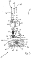
- zeigt eine Explosionsansicht des Ballastgasventils von
Fig. 1 . - Fig. 4
- zeigt eine perspektivische und teilweise transparente Ansicht einer Oberfläche eines Pumpenkörpers der erfindungsgemäßen Vakuumpumpe.
- In
Fig. 1 ist eine Ausführungsform eines Ballastgasventils 12 einer erfindungsgemäßen Vakuumpumpe 10, hier in Form einer Scrollpumpe, dargestellt. Das Ballastgasventil 12 ist an einer Haube 14 ausgebildet, die an einem Pumpenkörper 16 (sieheFig. 2 ) angebracht ist und an ihrer Außenseite Anzeigeelemente 18 aufweist. Die Haube 14 kann aus Kunststoff geformt sein und beispielsweise mittels eines Spritzgussverfahrens hergestellt sein. Im Bereich eines Ballastgaseinlasses weist die Haube 14 eine kreisförmige Vertiefung 20 für einen Drehkörper 22 zur Steuerung der Ballastgaszufuhr auf. - Wie
Fig. 2 zeigt, ist der Drehkörper 22 mit einer sich entlang einer Drehachse D des Drehkörpers 22 erstreckenden Aufnahmebohrung 34 zur Aufnahme einer Spannvorrichtung versehen, welche den Drehkörper 22 an dem Pumpenkörper 16 sichert und entlang der Drehachse D gegen eine ebene Anschlussfläche 17 des Pumpenkörpers 16 vorspannt. - Im gezeigten Ausführungsbeispiel umfasst die Spannvorrichtung eine Schraube 28, die in eine Gewindebohrung 30 des Pumpenkörpers 16 eingreift, um den Drehkörper 22 um die Drehachse D drehbar an dem Pumpenkörper 16 zu sichern. Die Schraube 28 bildet eine Schulter 28a aus, welche im maximal eingeschraubten Zustand der Schraube 28 auf der Anschlussfläche 17 des Pumpenkörpers 16 aufsitzt und hierdurch die Vorspannkraft begrenzt, die auf den Drehkörper 22 wirkt, welcher zwischen dem Schraubenkopf 28b und dem Pumpenkörper 16 gehalten ist. Alternativ oder zusätzlich kann die Spannvorrichtung auch ein in der Aufnahmebohrung 34 angeordnetes und entlang der Drehachse D wirkendes Federelement umfassen, gegen dessen Rückstellkraft die Schraube 28 festgezogen wird.
- Wie
Fig. 2 und3 ferner zeigen, ist der Drehkörper 22 zweistückig ausgebildet. Ein erster, dem Pumpenkörper 16 abgewandter Abschnitt bildet ein Kopfstück 24 und kann aus einem Kunststoff- oder Metallmaterial gefertigt sein. Ein zweiter, dem Pumpenkörper 16 zugewandter Abschnitt ist in Form einer Gleitscheibe 26 ausgebildet, die ebenfalls aus einem Kunststoff- oder Metallmaterial gefertigt sein kann. Eine dem Pumpenkörper 16 zugewandte Unterseite der Gleitscheibe 26 ist mit einer Gleitschicht aus einem Trockenschmiermittel, wie beispielsweise PTFE oder MoS2, beschichtet. - Das Kopfstück 24 und die Gleitscheibe 26 des Drehkörpers 22 sind mithilfe von mehreren, im vorliegenden Ausführungsbeispiel drei, Verbindungselementen 32, die durch zur Drehachse D parallele Bohrungen 36 im Kopfstück 24 und in der Gleitscheibe 26 geführt sind, miteinander verbunden. Konkret sind die Verbindungselemente 32 als Inbusschrauben ausgebildet, die sich durch das Kopfstück 24 hindurch erstrecken und in Gewindebohrungen 30 der Gleitscheibe 26 eingeschraubt sind.
- In dem Drehkörper 22 ist ferner eine parallel zur Drehachse D verlaufende Bohrung 38 zur Aufnahme eines Führungselements 40 ausgebildet, das sich durch die Gleitscheibe 26 hindurch erstreckt und teilweise in das Kopfstück 24 hineinragt. Das Führungselement 40 ist als Metallstift ausgebildet und weist an seinem dem Pumpenkörper 16 zugewandten Ende eine federbelaste Kugel 42 auf. Die Kugel 42 ist in Längsrichtung des Führungselements 40 verschiebbar gelagert und kann entgegen der Rückstellkraft eines nicht gezeigten Federelements zumindest teilweise in das Führungselement 40 hineingeschoben werden.
- Parallel versetzt zur Drehachse D ist eine Ventilbohrung 44 in dem Drehkörper 22 ausgebildet, welche eine Einlassöffnung 46 und eine Auslassöffnung 48 definiert. Im Bereich der Einlassöffnung 46 ist ein Anschlussstutzen 50 in die Ventilbohrung 44 eingesetzt, über welchen ein Ballastgas in die Ventilbohrung 44 eingeleitet werden kann. Zur Abdichtung des Anschlussstutzens 50 gegenüber dem Drehkörper 22 ist ein Dichtring 52 vorgesehen.
- Die Ventilbohrung 44 erstreckt sich sowohl durch das Kopfstück 24 und die Gleitscheibe 26 des Drehkörpers 22 und setzt sich aus mehreren Bohrungsabschnitten zusammen. Ein von der Einlassöffnung 46 ausgehender, im Kopfstück 24 ausgebildeter erster Bohrungsabschnitt weist eine geringere Querschnittsfläche auf als ein sich daran anschließender, ebenfalls im Kopfstück 24 befindlicher zweiter Bohrungsabschnitt. Der zweite Bohrungsabschnitt kommuniziert mit einem sich durch die Gleitscheibe 26 hindurch erstreckenden dritten Bohrungsabschnitt, welcher in die Auslassöffnung 48 mündet. Aufgrund der unterschiedlichen Querschnittsflächen des ersten und zweiten Bohrungsabschnitts bildet die Ventilbohrung 44 im Übergang von dem ersten Bohrungsabschnitt zu dem zweiten Bohrungsabschnitt einen Ventilsitz 54 für einen in dem zweiten Bohrungsabschnitt verschiebbar gelagerten Ventilkörper 56 aus, welcher durch ein Federelement 57, hier in Form einer Schraubendruckfeder, gegen den Ventilsitz 54 gedrückt wird. Der Ventilsitz 54 und der Ventilkörper 56 bilden auf diese Weise ein Rückschlagventil 53, welches eine Rückströmung sowohl des durch den Anschlussstutzen 50 in die Ventilbohrung 44 eingeleiteten Ballastgases als auch des durch die Vakuumpumpe gepumpten Mediums verhindert.
- Zur Weiterleitung des in die Ventilbohrung 44 des Drehkörpers 22 eingeleiteten Ballastgases in einen nicht gezeigten Pumpraum im Inneren des Pumpenkörpers 16 sind zwei Kanäle 58 in dem Pumpenkörper 16 ausgebildet, die jeweils einen Kanaleingang 60 und einen nicht gezeigten Kanalausgang aufweisen. Die Kanalausgänge der Kanäle 58 münden in unterschiedliche Bereiche des Pumpraums, beispielsweise in durch eine spiralförmige Wand getrennte Bereiche einer Scrollpumpe.
- Zusätzlich können die Kanalausgänge unterschiedlich große Querschnittsflächen aufweisen, so dass sich durch die Kanäle 58 unterschiedliche Mengen von Ballastgas pro Zeiteinheit in den Pumpraum einleiten lassen. Im vorliegenden Ausführungsbeispiel ist durch den ersten Kanal 58 eine geringere Menge von Ballastgas pro Zeiteinheit in den Pumpraum zuführbar als durch den zweiten Kanal 58. Jedenfalls sind die maximalen Abmessungen der Kanalausgänge jeweils gleich oder kleiner als die Breite eines nicht gezeigten Trennelements, das zwei Teilbereiche des Pumpraums voneinander trennt und sich im Betrieb der Vakuumpumpe 10 über einen oder beide Kanalausgänge hinweg bewegt, beispielsweise einer spiralförmigen Wand der Scrollpumpe. Die Kanäle 58 können sowohl orthogonal zur Anschlussfläche 17 des Pumpenkörpers 16 verlaufen als auch beliebig schiefwinklig, um eine vorgegebene, entfernt angeordnete Auslassöffnung 48 oder einen Kanal beginnend mit der Auslassöffnung 48 im Pumpenkörper 16 zu erreichen und damit eine Verbindung zwischen Kanaleingang 60 und Auslassöffnung 48 zu schaffen.
- Die Querschnittsfläche der Auslassöffnung 48 der Ventilbohrung 44 ist an die Querschnittsfläche der Kanaleingänge 60 angepasst und wird zumindest ähnlich oder gleich, bevorzugt kleiner gewählt als die Querschnittsflächen der Kanaleingänge 60. Zusätzlich sind die Kanaleingänge 60 von Dichtringen 62 umschlossen, die in entsprechenden Nuten 64 des Pumpenkörpers 16 aufgenommen sind. Die Dichtringe 62 bilden eine Auflagefläche für den Drehkörper 22, das heißt der Dichtkörper 22 steht ausschließlich mit den Dichtringen 62 in Kontakt, nicht aber mit der Oberfläche des Pumpenkörpers 16.
- Zur Verminderung der Reibung zwischen dem Drehkörper 22 und den Dichtringen 62 sind die Dichtringe 62 mit einem Trockenschmiermittel versehen. Beispielsweise können die Dichtringe 62 mit einem PTFE-Lack beschichtet sein. Die ausschließliche Verwendung von Trockenschmiermitteln wie PTFE oder MoS2 vermindert die Kontamination des Pumpraums mit Schmiermittelpartikeln, die über die Kanäle 58 in den Pumpraum gelangen könnten. Im Übrigen weisen Trockenschmiermittel im Vergleich zu Schmiermitteln wie Fett oder Öl einen geringeren Verschleiß auf und erlauben einen wartungsärmeren und kostengünstigeren Betrieb der Vakuumpumpe 10.
- Weiterhin verflüchtigen bzw. verkriechen sich Trockenschmiermittel nicht so leicht wie flüssige Schmiermittel, die fortfließen, verdunsten oder verdampfen können. Dies betrifft vor allem den Betrieb der Pumpe mit hohen Gehäusetemperaturen, die die Viskosität des flüssigen Schmiermittels herabsetzen und Bestandteile mit niedrigen Siedepunkten verflüchtigen lassen kann. Eine Kombination von trockenen und flüssigen Schmiermitteln, zum Beispiel PTFE und ein Öl, kann vorteilhaft zu einer nochmals erhöhten Lebensdauer und Schmierfähigkeit führen, vor allem auch zu einer erhöhten Notlaufsicherheit für den Fall, dass eine der beiden Komponenten unerwartet oder durch nicht vorgesehene Nutzung ungeplant versagt bzw. sich verflüchtigt.
- Um einer Verkippung des Drehkörpers 22 auf der aus den Dichtringen 62 gebildeten Auflagefläche entgegenzuwirken, ist zumindest ein zusätzlicher Dichtring 66 vorgesehen, der ein Blindelement ohne Verbindung zu einem Kanal 58 bildet. Durch eine zumindest annähernd symmetrische Anordnung der drei Dichtringe 62, 66 wird eine Auflagefläche geschaffen, die planparallel zu der Oberfläche des Pumpenkörpers 16 verläuft und den Drehkörper 22 während einer Drehung in einer entsprechenden planparallelen Lage hält.
- Zur zusätzlichen Führung des Drehkörpers 22 während seiner Verdrehung ist an der Oberfläche des Pumpenkörpers 16 eine teilkreisförmige Führungskulisse 68 ausgebildet, in die das an dem Drehkörper 22 angebrachte Führungselement 40 eingreift, wie es in der perspektivischen Ansicht in
Fig. 4 gezeigt ist. Die Führungskulisse 68 weist drei Vertiefungen 70 auf, in welche die federbelastete Kugel 42 des Führungselements 40 jeweils einrastet, wenn sich der Drehkörper 22 in einer ersten Öffnungsstellung, in welcher die Auslassöffnung 48 mit dem Eingang des ersten Kanals 58 ausgerichtet ist, in einer zweiten Öffnungsstellung, in welcher die Auslassöffnung 48 mit dem Eingang des zweiten Kanals 58 ausgerichtet ist, und in einer Verschlussstellung befindet, in welcher die Auslassöffnung 48 weder mit dem Eingang des ersten Kanals 58, noch mit dem Eingang des zweiten Kanals 58 ausgerichtet ist. Diese Rastpositionen erleichtern das Auffinden und Einstellen des korrekten Drehwinkels des Drehkörpers 22 für die Öffnungsstellungen bzw. für die Verschlussstellung. - Als weitere Einstellhilfe sind an der Haube 14 Anzeigeelemente 18, beispielsweise in Form von Beschriftungen, angebracht, die auf den einzustellenden korrekten Drehwinkel für die Öffnungsstellungen und die Verschlussstellung hinweisen. Zur Anzeige des aktuellen Drehwinkels ist der Drehkörper 22 nichtkreisförmig ausgeformt, insbesondere weist das Kopfstück 24 des Drehkörpers 22 im dargestellten Ausführungsbeispiel eine ansatzweise pfeilförmige Grundform auf, wobei die Pfeilspitze in Richtung des aktuellen Drehwinkels weist. Alternativ sind auch ovale oder andere nicht kreisförmige Ausbildungen des Drehkörpers 22 möglich, die sich einfach greifen und leicht manuell betätigen lassen. Dabei ist auch denkbar, dass an dem Drehkörper 22 zusätzliche Markierungen angebracht sind, die auf den aktuellen Drehwinkel des Drehkörpers 22 hinweisen.
- Zur Einleitung von Ballastgas in den Pumpraum wird der Anschlussstutzen 50 mittels einer nicht gezeigten Verbindungsleitung mit einem ebenfalls nicht gezeigten Ballastgasbehälter verbunden und der Drehkörper 22 in die gewünschte Öffnungsstellung gedreht, bis das Führungselement 40 in die entsprechende Vertiefung 70 der Führungskulisse 68 einrastet. Durch das in die Ventilbohrung 44 strömende Ballastgas wird der Ventilkörper 56 von dem Ventilsitz 54 abgehoben, sodass das Ballastgas durch den Kanaleingang 60 in den gewählten Kanal 58 strömen und durch den Ausgang des jeweiligen Kanals 58 in den Pumpraum der Vakuumpumpe 10 gelangen kann.
- Durch Verdrehung des Drehkörpers 22 aus der einen Öffnungsstellung in die andere Öffnungsstellung kann der Ort der Einleitung des Ballastgases in den Pumpraum und auch die Menge des in den Pumpraum eingeleiteten Ballastgases pro Zeiteinheit verändert werden. Durch die Anordnung des Rückschlagventils 53 innerhalb des Drehkörpers 22 besteht weiterhin der Vorteil gegenüber bekannten Lösungen, dass nur ein Rückschlagventil 53 für eine beliebige Anzahl von Einleitungsstellen bzw. Kanälen 58 benötigt wird.
- Dabei versteht es sich, dass, obwohl die Erfindung voranstehend anhand eines zweistufigen Ventils beschrieben wurde, Ausführungsformen denkbar sind, die zusätzlich zu den beschriebenen zwei Stufen weitere Stufen der Ballastgaszufuhr ermöglichen, indem zusätzliche Kanäle im Pumpenkörper 16 ausgebildet werden, mit deren Eingängen die Auslassöffnung 48 des Drehkörpers 22 ausgerichtet werden kann.
- Weiterhin versteht es sich, dass, obwohl die Erfindung voranstehend eine solche Abdichtung nicht aufweist, ein weiteres Dichtelement so auf der Anschlussfläche 17 angeordnet sein kann, dass dieses die Auslassöffnung 48 in Verschluss- bzw. Nullstellung des Ballastgasventils 12 dicht verschließt, so dass in dieser Stellung bei bestehenden Druckunterschieden kein Ballastgas durch den zwischen Gleitscheibe 26 und Kanaleingang 60 gebildeten Spalt in die Umgebung austreten kann oder umgekehrt Umgebungsluft in die Ballastgasleitung eintreten kann.
- Zuletzt versteht es sich, dass, obwohl die Erfindung voranstehend eine solche Führungskulisse 68 nicht aufweist, eine solche auch ohne Unterbrechung durchgehend ausgeführt sein kann oder dass die Vertiefungen 70 auch ohne Führungskulisse 68 direkt auf der Anschlussfläche 17 auf einem zur Drehachse D konzentrischen Kreis angeordnet sein können, so dass die federbelastete Kugel 42 in diese einrasten kann. Entsprechend kann der Drehkörper 22 beliebige Male in beliebige Richtung um die Drehachse D gedreht werden, da keine geometrische Begrenzung vorliegt.
-
- 10
- Vakuumpumpe
- 12
- Ballastgasventil
- 14
- Haube
- 16
- Pumpenkörper
- 17
- Anschlussfläche
- 18
- Anzeigeelement
- 20
- Vertiefung
- 22
- Drehkörper
- 24
- Kopfstück
- 26
- Gleitscheibe
- 28
- Schraube
- 28a
- Schulter
- 28b
- Schraubenkopf
- 30
- Gewindebohrung
- 32
- Verbindungselement
- 34
- Aufnahmebohrung
- 36
- Bohrung
- 38
- Bohrung
- 40
- Führungselement
- 42
- federbelastete Kugel
- 44
- Ventilbohrung
- 46
- Einlassöffnung
- 48
- Auslassöffnung
- 50
- Anschlussstutzen
- 52
- Dichtring
- 53
- Rückschlagventil
- 54
- Ventilsitz
- 56
- Ventilkörper
- 57
- Federelement
- 58
- Kanal
- 60
- Kanaleingang
- 62
- Dichtring
- 64
- Nut
- 66
- Dichtring
- 68
- Führungskulisse
- 70
- Vertiefung
Claims (15)
- Vakuumpumpe (10) mit einem Pumpenkörper (16), dessen Innenseite einen Pumpraum begrenzt und an dessen Außenseite ein Ventil (12) zur Steuerung der Zufuhr eines Ballastgases in den Pumpraum angeordnet ist, wobei das Ventil (12) eine Einlassöffnung (46) und eine Auslassöffnung (48) aufweist,
dadurch gekennzeichnet, dass
ein erster und ein zweiter Kanal (58) in dem Pumpenkörper (16) ausgebildet sind, wobei der Eingang (60) jedes Kanals (58) dem Ventil (12) zugewandt ist und der Ausgang jedes Kanals (58) in den Pumpraum mündet, und
das Ventil (12) zwischen einer ersten und einer zweiten Öffnungsstellung verstellbar ist, wobei die Auslassöffnung (48) in der ersten Öffnungsstellung mit dem Eingang (60) des ersten Kanals (58) und in der zweiten Öffnungsstellung mit dem Eingang (60) des zweiten Kanals (58) ausgerichtet ist. - Vakuumpumpe (10) nach Anspruch 1,
dadurch gekennzeichnet, dass
das Ventil (12) zumindest eine weitere Stellung aufweist, in welcher die Auslassöffnung (48) mit keinem der Kanaleingänge (60) ausgerichtet ist. - Vakuumpumpe (10) nach Anspruch 1 oder 2,
dadurch gekennzeichnet, dass
das Ventil (12) ein Rückschlagventil (53) aufweist, welches eine Rückströmung von Gasen von der Auslassöffnung (48) zur Einlassöffnung (46) verhindert. - Vakuumpumpe (10) nach zumindest einem der vorstehenden Ansprüche,
dadurch gekennzeichnet, dass
der erste und zweite Kanal (58) unterschiedliche Längen aufweisen. - Vakuumpumpe (10) nach zumindest einem der vorstehenden Ansprüche,
dadurch gekennzeichnet, dass
die Ausgänge des ersten und zweiten Kanals (58) unterschiedliche Querschnittsflächen aufweisen. - Vakuumpumpe (10) nach zumindest einem der vorstehenden Ansprüche,
dadurch gekennzeichnet, dass
eine maximale Abmessung des Ausgangs eines oder jedes Kanals (58) gleich oder kleiner ist als eine Breite eines Trennelements, das zwei Bereiche des Pumpraums voneinander trennt und sich im Betrieb der Vakuumpumpe (10) über den oder jeden Ausgang hinweg bewegt. - Vakuumpumpe (10) nach zumindest einem der vorstehenden Ansprüche,
dadurch gekennzeichnet, dass
das Ventil (12) einen Drehkörper (22) umfasst, der an dem Pumpenkörper (16) drehbar gelagert ist, insbesondere wobei eine Drehachse D des Drehkörpers (22) orthogonal zu einer ebenen Anschlussfläche (17) an dem Pumpenkörper (16) angeordnet ist, wobei die Kanaleingänge (60) in der Anschlussfläche (17) angeordnet sind. - Vakuumpumpe (10) nach Anspruch 7,
dadurch gekennzeichnet, dass
das Ventil (12) durch Drehung des Drehkörpers (22) zumindest zwischen der ersten und der zweiten Öffnungsstellung verstellbar ist. - Vakuumpumpe (10) nach Anspruch 7 oder 8,
dadurch gekennzeichnet, dass
die Eingänge (60) der Kanäle jeweils von einem Dichtelement (62), insbesondere Dichtring, umschlossen sind. - Vakuumpumpe (10) nach zumindest einem der Ansprüche 7 bis 9,
dadurch gekennzeichnet, dass
wenigstens drei Dichtelemente (62, 66), insbesondere Dichtringe, vorgesehen sind, welche um eine Drehachse D des Drehkörpers (22) herum verteilt, insbesondere zumindest annähernd symmetrisch, angeordnet sind. - Vakuumpumpe (10) nach zumindest einem der Ansprüche 7 bis 10,
dadurch gekennzeichnet, dass
der Drehkörper (22) an seiner dem Pumpenkörper (16) zugewandten Unterseite und/oder die Dichteelemente (62, 66) zumindest auf ihrer dem Drehkörper (22) zugewandten Seite mit einem Trockenschmiermittel versehen sind bzw. ist. - Vakuumpumpe (10) nach zumindest einem der Ansprüche 7 bis 11,
dadurch gekennzeichnet, dass
der Drehkörper (22) eine Spannvorrichtung (28) aufweist, um den Drehkörper (22), insbesondere entlang seiner Drehachse D, gegen den Pumpenkörper (16) vorzuspannen. - Vakuumpumpe (10) nach zumindest einem der Ansprüche 7 bis 12,
dadurch gekennzeichnet, dass
der Pumpenkörper (16) eine teilkreisförmige Führungskulisse (68) ausbildet und der Drehkörper (22) mit einem Führungselement (40) versehen ist, das aus der dem Pumpenkörper (16) zugewandten Unterseite des Drehkörpers (22) herausragt und in der Führungskulisse (68) des Pumpenkörpers (16) geführt ist. - Vakuumpumpe (10) nach Anspruch 13,
dadurch gekennzeichnet, dass
das Führungselement (40) einen federbelasteten Kugelkörper (42) aufweist, der in die Führungskulisse (68) eingreift, wobei die Führungskulisse (68) Vertiefungen (70) an den der zumindest ersten und zweiten Öffnungsstellung entsprechenden Positionen aufweist. - Vakuumpumpe (10) nach zumindest einem der Ansprüche 7 bis 14,
dadurch gekennzeichnet, dass
an einer Außenseite des Pumpenkörpers (16) Beschriftungen (18) angebracht sind, die den korrekten Drehwinkel des Drehkörpers (22) für die zumindest erste oder zweite Öffnungsstellung anzeigen, und/oder der Drehkörper (22) einen nichtkreisförmigen Querschnitt aufweist, insbesondere einen richtungsanzeigenden Querschnitt.
Priority Applications (2)
| Application Number | Priority Date | Filing Date | Title |
|---|---|---|---|
| EP17201444.1A EP3483448B1 (de) | 2017-11-13 | 2017-11-13 | Vakuumpumpe mit ballastgasventil |
| JP2018209351A JP6738114B2 (ja) | 2017-11-13 | 2018-11-07 | バラストガスのバルブを有する真空ポンプ |
Applications Claiming Priority (1)
| Application Number | Priority Date | Filing Date | Title |
|---|---|---|---|
| EP17201444.1A EP3483448B1 (de) | 2017-11-13 | 2017-11-13 | Vakuumpumpe mit ballastgasventil |
Publications (2)
| Publication Number | Publication Date |
|---|---|
| EP3483448A1 true EP3483448A1 (de) | 2019-05-15 |
| EP3483448B1 EP3483448B1 (de) | 2020-05-13 |
Family
ID=60327120
Family Applications (1)
| Application Number | Title | Priority Date | Filing Date |
|---|---|---|---|
| EP17201444.1A Active EP3483448B1 (de) | 2017-11-13 | 2017-11-13 | Vakuumpumpe mit ballastgasventil |
Country Status (2)
| Country | Link |
|---|---|
| EP (1) | EP3483448B1 (de) |
| JP (1) | JP6738114B2 (de) |
Cited By (5)
| Publication number | Priority date | Publication date | Assignee | Title |
|---|---|---|---|---|
| EP3636879A1 (de) * | 2019-11-20 | 2020-04-15 | Pfeiffer Vacuum Gmbh | Vakuumpumpe |
| CN112761955A (zh) * | 2021-01-18 | 2021-05-07 | 浙江飞越机电有限公司 | 一种用于旋片式真空泵的气镇结构 |
| CN113982948A (zh) * | 2021-11-17 | 2022-01-28 | 广东美芝制冷设备有限公司 | 阀座组件及压缩机 |
| EP4174316A1 (de) * | 2021-10-29 | 2023-05-03 | Agilent Technologies, Inc. | Vakuumpumpe mit einer gasballastanordnung |
| CN118242273A (zh) * | 2024-03-27 | 2024-06-25 | 金华市威科工贸有限公司 | 多功能真空泵 |
Citations (2)
| Publication number | Priority date | Publication date | Assignee | Title |
|---|---|---|---|---|
| DE951884C (de) * | 1953-12-23 | 1956-11-08 | Leybold S Nachfolger E | Vakuumpumpe |
| GB2196696A (en) * | 1986-10-22 | 1988-05-05 | Utile Engineering Co Limited | Rotary vane pumps operable in vacuum mode |
-
2017
- 2017-11-13 EP EP17201444.1A patent/EP3483448B1/de active Active
-
2018
- 2018-11-07 JP JP2018209351A patent/JP6738114B2/ja active Active
Patent Citations (2)
| Publication number | Priority date | Publication date | Assignee | Title |
|---|---|---|---|---|
| DE951884C (de) * | 1953-12-23 | 1956-11-08 | Leybold S Nachfolger E | Vakuumpumpe |
| GB2196696A (en) * | 1986-10-22 | 1988-05-05 | Utile Engineering Co Limited | Rotary vane pumps operable in vacuum mode |
Cited By (6)
| Publication number | Priority date | Publication date | Assignee | Title |
|---|---|---|---|---|
| EP3636879A1 (de) * | 2019-11-20 | 2020-04-15 | Pfeiffer Vacuum Gmbh | Vakuumpumpe |
| CN112761955A (zh) * | 2021-01-18 | 2021-05-07 | 浙江飞越机电有限公司 | 一种用于旋片式真空泵的气镇结构 |
| EP4174316A1 (de) * | 2021-10-29 | 2023-05-03 | Agilent Technologies, Inc. | Vakuumpumpe mit einer gasballastanordnung |
| CN113982948A (zh) * | 2021-11-17 | 2022-01-28 | 广东美芝制冷设备有限公司 | 阀座组件及压缩机 |
| CN113982948B (zh) * | 2021-11-17 | 2023-03-14 | 广东美芝制冷设备有限公司 | 阀座组件及压缩机 |
| CN118242273A (zh) * | 2024-03-27 | 2024-06-25 | 金华市威科工贸有限公司 | 多功能真空泵 |
Also Published As
| Publication number | Publication date |
|---|---|
| EP3483448B1 (de) | 2020-05-13 |
| JP2019113060A (ja) | 2019-07-11 |
| JP6738114B2 (ja) | 2020-08-12 |
Similar Documents
| Publication | Publication Date | Title |
|---|---|---|
| EP3483448B1 (de) | Vakuumpumpe mit ballastgasventil | |
| EP0818629B1 (de) | Hydraulische Stelleinheit und Verfahren zum Entlüften einer hydraulischen Stelleinheit | |
| EP2488776B1 (de) | Druckhalteventil | |
| DE3513461C2 (de) | ||
| EP0495458A2 (de) | Rohrtrenner | |
| DE3140742A1 (de) | "pumpe, insbesondere zum foerdern einer giftigen fluesigkeit" | |
| DE2949231C2 (de) | Druckmittelventil, insbesondere Druckreduzierventil | |
| DE102016219720A1 (de) | Druckventil | |
| WO1998031936A1 (de) | Hubkolbenkompressor | |
| DE1403973A1 (de) | Dosierungspumpe | |
| DE19717807B4 (de) | Von mindestens einem Elektromagneten betätigbares Wegeventil | |
| DE102021207650A1 (de) | Schieberventil mit geringer Neigung zum hydraulischen Klemmen | |
| DE2900601C2 (de) | Absperrventil für ein Fluid | |
| DE3882949T2 (de) | Hin- und herbewegende schaltungsstrukttur für pumpe. | |
| EP3859159B1 (de) | Schraubenverdichter | |
| DE351319T1 (de) | Ventil, fluessigkeitssteuerungseinrichtung und mit einem solchen ventil ausgestatteter rueckflussverhinderer. | |
| DE102018113616A1 (de) | Peristaltikpumpe | |
| EP1696161B1 (de) | Schiebeventil | |
| DE2556708C2 (de) | Für die Blockbauweise vorgesehenes Hydrowegeventil | |
| DE3003879C2 (de) | Ventilanordnung, insbesondere für Hochdruckkolbenpumpen | |
| EP1000665A2 (de) | Rotordüse | |
| DE3518472A1 (de) | Druckbegrenzungsventil | |
| DE3900963C2 (de) | ||
| DE202017003786U1 (de) | Ventilanordnung und Ventilbaugruppe | |
| EP0740094A1 (de) | Rückschlagventil mit Schauglas |
Legal Events
| Date | Code | Title | Description |
|---|---|---|---|
| PUAI | Public reference made under article 153(3) epc to a published international application that has entered the european phase |
Free format text: ORIGINAL CODE: 0009012 |
|
| STAA | Information on the status of an ep patent application or granted ep patent |
Free format text: STATUS: THE APPLICATION HAS BEEN PUBLISHED |
|
| AK | Designated contracting states |
Kind code of ref document: A1 Designated state(s): AL AT BE BG CH CY CZ DE DK EE ES FI FR GB GR HR HU IE IS IT LI LT LU LV MC MK MT NL NO PL PT RO RS SE SI SK SM TR |
|
| AX | Request for extension of the european patent |
Extension state: BA ME |
|
| STAA | Information on the status of an ep patent application or granted ep patent |
Free format text: STATUS: REQUEST FOR EXAMINATION WAS MADE |
|
| 17P | Request for examination filed |
Effective date: 20191115 |
|
| RBV | Designated contracting states (corrected) |
Designated state(s): AL AT BE BG CH CY CZ DE DK EE ES FI FR GB GR HR HU IE IS IT LI LT LU LV MC MK MT NL NO PL PT RO RS SE SI SK SM TR |
|
| GRAP | Despatch of communication of intention to grant a patent |
Free format text: ORIGINAL CODE: EPIDOSNIGR1 |
|
| STAA | Information on the status of an ep patent application or granted ep patent |
Free format text: STATUS: GRANT OF PATENT IS INTENDED |
|
| RIC1 | Information provided on ipc code assigned before grant |
Ipc: F04C 28/24 20060101ALI20200108BHEP Ipc: F04C 29/12 20060101ALI20200108BHEP Ipc: F04C 25/02 20060101AFI20200108BHEP Ipc: F04B 39/12 20060101ALI20200108BHEP Ipc: F04B 39/10 20060101ALI20200108BHEP |
|
| INTG | Intention to grant announced |
Effective date: 20200123 |
|
| GRAS | Grant fee paid |
Free format text: ORIGINAL CODE: EPIDOSNIGR3 |
|
| GRAA | (expected) grant |
Free format text: ORIGINAL CODE: 0009210 |
|
| STAA | Information on the status of an ep patent application or granted ep patent |
Free format text: STATUS: THE PATENT HAS BEEN GRANTED |
|
| AK | Designated contracting states |
Kind code of ref document: B1 Designated state(s): AL AT BE BG CH CY CZ DE DK EE ES FI FR GB GR HR HU IE IS IT LI LT LU LV MC MK MT NL NO PL PT RO RS SE SI SK SM TR |
|
| REG | Reference to a national code |
Ref country code: GB Ref legal event code: FG4D Free format text: NOT ENGLISH |
|
| REG | Reference to a national code |
Ref country code: CH Ref legal event code: EP |
|
| REG | Reference to a national code |
Ref country code: DE Ref legal event code: R096 Ref document number: 502017005233 Country of ref document: DE |
|
| REG | Reference to a national code |
Ref country code: AT Ref legal event code: REF Ref document number: 1270653 Country of ref document: AT Kind code of ref document: T Effective date: 20200615 |
|
| REG | Reference to a national code |
Ref country code: LT Ref legal event code: MG4D |
|
| REG | Reference to a national code |
Ref country code: NL Ref legal event code: MP Effective date: 20200513 |
|
| PG25 | Lapsed in a contracting state [announced via postgrant information from national office to epo] |
Ref country code: PT Free format text: LAPSE BECAUSE OF FAILURE TO SUBMIT A TRANSLATION OF THE DESCRIPTION OR TO PAY THE FEE WITHIN THE PRESCRIBED TIME-LIMIT Effective date: 20200914 Ref country code: LT Free format text: LAPSE BECAUSE OF FAILURE TO SUBMIT A TRANSLATION OF THE DESCRIPTION OR TO PAY THE FEE WITHIN THE PRESCRIBED TIME-LIMIT Effective date: 20200513 Ref country code: FI Free format text: LAPSE BECAUSE OF FAILURE TO SUBMIT A TRANSLATION OF THE DESCRIPTION OR TO PAY THE FEE WITHIN THE PRESCRIBED TIME-LIMIT Effective date: 20200513 Ref country code: SE Free format text: LAPSE BECAUSE OF FAILURE TO SUBMIT A TRANSLATION OF THE DESCRIPTION OR TO PAY THE FEE WITHIN THE PRESCRIBED TIME-LIMIT Effective date: 20200513 Ref country code: GR Free format text: LAPSE BECAUSE OF FAILURE TO SUBMIT A TRANSLATION OF THE DESCRIPTION OR TO PAY THE FEE WITHIN THE PRESCRIBED TIME-LIMIT Effective date: 20200814 Ref country code: IS Free format text: LAPSE BECAUSE OF FAILURE TO SUBMIT A TRANSLATION OF THE DESCRIPTION OR TO PAY THE FEE WITHIN THE PRESCRIBED TIME-LIMIT Effective date: 20200913 Ref country code: NO Free format text: LAPSE BECAUSE OF FAILURE TO SUBMIT A TRANSLATION OF THE DESCRIPTION OR TO PAY THE FEE WITHIN THE PRESCRIBED TIME-LIMIT Effective date: 20200813 |
|
| PG25 | Lapsed in a contracting state [announced via postgrant information from national office to epo] |
Ref country code: BG Free format text: LAPSE BECAUSE OF FAILURE TO SUBMIT A TRANSLATION OF THE DESCRIPTION OR TO PAY THE FEE WITHIN THE PRESCRIBED TIME-LIMIT Effective date: 20200813 Ref country code: HR Free format text: LAPSE BECAUSE OF FAILURE TO SUBMIT A TRANSLATION OF THE DESCRIPTION OR TO PAY THE FEE WITHIN THE PRESCRIBED TIME-LIMIT Effective date: 20200513 Ref country code: RS Free format text: LAPSE BECAUSE OF FAILURE TO SUBMIT A TRANSLATION OF THE DESCRIPTION OR TO PAY THE FEE WITHIN THE PRESCRIBED TIME-LIMIT Effective date: 20200513 Ref country code: LV Free format text: LAPSE BECAUSE OF FAILURE TO SUBMIT A TRANSLATION OF THE DESCRIPTION OR TO PAY THE FEE WITHIN THE PRESCRIBED TIME-LIMIT Effective date: 20200513 |
|
| PG25 | Lapsed in a contracting state [announced via postgrant information from national office to epo] |
Ref country code: AL Free format text: LAPSE BECAUSE OF FAILURE TO SUBMIT A TRANSLATION OF THE DESCRIPTION OR TO PAY THE FEE WITHIN THE PRESCRIBED TIME-LIMIT Effective date: 20200513 Ref country code: NL Free format text: LAPSE BECAUSE OF FAILURE TO SUBMIT A TRANSLATION OF THE DESCRIPTION OR TO PAY THE FEE WITHIN THE PRESCRIBED TIME-LIMIT Effective date: 20200513 |
|
| PG25 | Lapsed in a contracting state [announced via postgrant information from national office to epo] |
Ref country code: SM Free format text: LAPSE BECAUSE OF FAILURE TO SUBMIT A TRANSLATION OF THE DESCRIPTION OR TO PAY THE FEE WITHIN THE PRESCRIBED TIME-LIMIT Effective date: 20200513 Ref country code: EE Free format text: LAPSE BECAUSE OF FAILURE TO SUBMIT A TRANSLATION OF THE DESCRIPTION OR TO PAY THE FEE WITHIN THE PRESCRIBED TIME-LIMIT Effective date: 20200513 Ref country code: DK Free format text: LAPSE BECAUSE OF FAILURE TO SUBMIT A TRANSLATION OF THE DESCRIPTION OR TO PAY THE FEE WITHIN THE PRESCRIBED TIME-LIMIT Effective date: 20200513 Ref country code: ES Free format text: LAPSE BECAUSE OF FAILURE TO SUBMIT A TRANSLATION OF THE DESCRIPTION OR TO PAY THE FEE WITHIN THE PRESCRIBED TIME-LIMIT Effective date: 20200513 Ref country code: RO Free format text: LAPSE BECAUSE OF FAILURE TO SUBMIT A TRANSLATION OF THE DESCRIPTION OR TO PAY THE FEE WITHIN THE PRESCRIBED TIME-LIMIT Effective date: 20200513 |
|
| REG | Reference to a national code |
Ref country code: DE Ref legal event code: R097 Ref document number: 502017005233 Country of ref document: DE |
|
| PG25 | Lapsed in a contracting state [announced via postgrant information from national office to epo] |
Ref country code: PL Free format text: LAPSE BECAUSE OF FAILURE TO SUBMIT A TRANSLATION OF THE DESCRIPTION OR TO PAY THE FEE WITHIN THE PRESCRIBED TIME-LIMIT Effective date: 20200513 Ref country code: SK Free format text: LAPSE BECAUSE OF FAILURE TO SUBMIT A TRANSLATION OF THE DESCRIPTION OR TO PAY THE FEE WITHIN THE PRESCRIBED TIME-LIMIT Effective date: 20200513 |
|
| PLBE | No opposition filed within time limit |
Free format text: ORIGINAL CODE: 0009261 |
|
| STAA | Information on the status of an ep patent application or granted ep patent |
Free format text: STATUS: NO OPPOSITION FILED WITHIN TIME LIMIT |
|
| 26N | No opposition filed |
Effective date: 20210216 |
|
| PG25 | Lapsed in a contracting state [announced via postgrant information from national office to epo] |
Ref country code: SI Free format text: LAPSE BECAUSE OF FAILURE TO SUBMIT A TRANSLATION OF THE DESCRIPTION OR TO PAY THE FEE WITHIN THE PRESCRIBED TIME-LIMIT Effective date: 20200513 |
|
| PG25 | Lapsed in a contracting state [announced via postgrant information from national office to epo] |
Ref country code: MC Free format text: LAPSE BECAUSE OF FAILURE TO SUBMIT A TRANSLATION OF THE DESCRIPTION OR TO PAY THE FEE WITHIN THE PRESCRIBED TIME-LIMIT Effective date: 20200513 |
|
| REG | Reference to a national code |
Ref country code: CH Ref legal event code: PL |
|
| PG25 | Lapsed in a contracting state [announced via postgrant information from national office to epo] |
Ref country code: LU Free format text: LAPSE BECAUSE OF NON-PAYMENT OF DUE FEES Effective date: 20201113 |
|
| REG | Reference to a national code |
Ref country code: BE Ref legal event code: MM Effective date: 20201130 |
|
| PG25 | Lapsed in a contracting state [announced via postgrant information from national office to epo] |
Ref country code: LI Free format text: LAPSE BECAUSE OF NON-PAYMENT OF DUE FEES Effective date: 20201130 Ref country code: CH Free format text: LAPSE BECAUSE OF NON-PAYMENT OF DUE FEES Effective date: 20201130 |
|
| PG25 | Lapsed in a contracting state [announced via postgrant information from national office to epo] |
Ref country code: FR Free format text: LAPSE BECAUSE OF NON-PAYMENT OF DUE FEES Effective date: 20201130 Ref country code: IE Free format text: LAPSE BECAUSE OF NON-PAYMENT OF DUE FEES Effective date: 20201113 |
|
| PG25 | Lapsed in a contracting state [announced via postgrant information from national office to epo] |
Ref country code: TR Free format text: LAPSE BECAUSE OF FAILURE TO SUBMIT A TRANSLATION OF THE DESCRIPTION OR TO PAY THE FEE WITHIN THE PRESCRIBED TIME-LIMIT Effective date: 20200513 Ref country code: MT Free format text: LAPSE BECAUSE OF FAILURE TO SUBMIT A TRANSLATION OF THE DESCRIPTION OR TO PAY THE FEE WITHIN THE PRESCRIBED TIME-LIMIT Effective date: 20200513 Ref country code: CY Free format text: LAPSE BECAUSE OF FAILURE TO SUBMIT A TRANSLATION OF THE DESCRIPTION OR TO PAY THE FEE WITHIN THE PRESCRIBED TIME-LIMIT Effective date: 20200513 |
|
| PG25 | Lapsed in a contracting state [announced via postgrant information from national office to epo] |
Ref country code: MK Free format text: LAPSE BECAUSE OF FAILURE TO SUBMIT A TRANSLATION OF THE DESCRIPTION OR TO PAY THE FEE WITHIN THE PRESCRIBED TIME-LIMIT Effective date: 20200513 |
|
| PG25 | Lapsed in a contracting state [announced via postgrant information from national office to epo] |
Ref country code: BE Free format text: LAPSE BECAUSE OF NON-PAYMENT OF DUE FEES Effective date: 20201130 |
|
| REG | Reference to a national code |
Ref country code: AT Ref legal event code: MM01 Ref document number: 1270653 Country of ref document: AT Kind code of ref document: T Effective date: 20221113 |
|
| PG25 | Lapsed in a contracting state [announced via postgrant information from national office to epo] |
Ref country code: AT Free format text: LAPSE BECAUSE OF NON-PAYMENT OF DUE FEES Effective date: 20221113 |
|
| PGFP | Annual fee paid to national office [announced via postgrant information from national office to epo] |
Ref country code: GB Payment date: 20251121 Year of fee payment: 9 |
|
| PGFP | Annual fee paid to national office [announced via postgrant information from national office to epo] |
Ref country code: IT Payment date: 20251125 Year of fee payment: 9 |
|
| PGFP | Annual fee paid to national office [announced via postgrant information from national office to epo] |
Ref country code: CZ Payment date: 20251105 Year of fee payment: 9 |
|
| PGFP | Annual fee paid to national office [announced via postgrant information from national office to epo] |
Ref country code: DE Payment date: 20260128 Year of fee payment: 9 |