EP3483408A1 - Brennkraftmaschine und verfahren zum betreiben der brennkraftmaschine - Google Patents
Brennkraftmaschine und verfahren zum betreiben der brennkraftmaschine Download PDFInfo
- Publication number
- EP3483408A1 EP3483408A1 EP18194391.1A EP18194391A EP3483408A1 EP 3483408 A1 EP3483408 A1 EP 3483408A1 EP 18194391 A EP18194391 A EP 18194391A EP 3483408 A1 EP3483408 A1 EP 3483408A1
- Authority
- EP
- European Patent Office
- Prior art keywords
- exhaust gas
- combustion engine
- exhaust
- internal combustion
- cylinder
- Prior art date
- Legal status (The legal status is an assumption and is not a legal conclusion. Google has not performed a legal analysis and makes no representation as to the accuracy of the status listed.)
- Granted
Links
Images



Classifications
-
- F—MECHANICAL ENGINEERING; LIGHTING; HEATING; WEAPONS; BLASTING
- F02—COMBUSTION ENGINES; HOT-GAS OR COMBUSTION-PRODUCT ENGINE PLANTS
- F02B—INTERNAL-COMBUSTION PISTON ENGINES; COMBUSTION ENGINES IN GENERAL
- F02B37/00—Engines characterised by provision of pumps driven at least for part of the time by exhaust
- F02B37/12—Control of the pumps
- F02B37/22—Control of the pumps by varying cross-section of exhaust passages or air passages, e.g. by throttling turbine inlets or outlets or by varying effective number of guide conduits
- F02B37/225—Control of the pumps by varying cross-section of exhaust passages or air passages, e.g. by throttling turbine inlets or outlets or by varying effective number of guide conduits air passages
-
- F—MECHANICAL ENGINEERING; LIGHTING; HEATING; WEAPONS; BLASTING
- F02—COMBUSTION ENGINES; HOT-GAS OR COMBUSTION-PRODUCT ENGINE PLANTS
- F02B—INTERNAL-COMBUSTION PISTON ENGINES; COMBUSTION ENGINES IN GENERAL
- F02B37/00—Engines characterised by provision of pumps driven at least for part of the time by exhaust
- F02B37/02—Gas passages between engine outlet and pump drive, e.g. reservoirs
- F02B37/025—Multiple scrolls or multiple gas passages guiding the gas to the pump drive
-
- Y—GENERAL TAGGING OF NEW TECHNOLOGICAL DEVELOPMENTS; GENERAL TAGGING OF CROSS-SECTIONAL TECHNOLOGIES SPANNING OVER SEVERAL SECTIONS OF THE IPC; TECHNICAL SUBJECTS COVERED BY FORMER USPC CROSS-REFERENCE ART COLLECTIONS [XRACs] AND DIGESTS
- Y02—TECHNOLOGIES OR APPLICATIONS FOR MITIGATION OR ADAPTATION AGAINST CLIMATE CHANGE
- Y02T—CLIMATE CHANGE MITIGATION TECHNOLOGIES RELATED TO TRANSPORTATION
- Y02T10/00—Road transport of goods or passengers
- Y02T10/10—Internal combustion engine [ICE] based vehicles
- Y02T10/12—Improving ICE efficiencies
Definitions
- the invention relates to an internal combustion engine with the features of the preamble of patent claim 1 and method for operating the internal combustion engine according to claims 6 and 7.
- the European Patent EP 2 115 284 B1 pointed. From this is an internal combustion engine with 8 cylinders in V-type, with an exhaust system with a first and a second exhaust gas turbocharger known, wherein of a first, a second, a third and a fourth, in series juxtaposed cylinder a first cylinder bank and of a fifth, a sixth, a seventh and an eighth, in series juxtaposed cylinder, a second, the first cylinder bank opposite cylinder bank is formed, wherein the internal combustion engine from cylinder to cylinder has a firing order of 90 ° crank angle, wherein the exhaust system a first, a second , a third and a fourth exhaust gas line from the cylinders to the two exhaust gas turbochargers, and wherein an exhaust gas line each two cylinders and two exhaust gas lines each an exhaust gas turbocharger is assigned, wherein two, an exhaust line associated cylinders have a firing interval of 360 ° crank angle and that the first and the second, an exhaust gas turbocharger
- a segment turbine is for example from the French patent application FR 2 801 072 A1
- their floods have no axial partition and thus does not allow two-point variability of the exhaust gas mass flow.
- a twin-flow turbine is for example from the German Offenlegungsschrift DE 10 2007 017 826 A1 known.
- the object of the present invention is to show a cost-effective solution for a variable exhaust gas mass flow for twin-flow turbines.
- the volutes additionally have an axial partition (twin-scroll) and which is connected to the outlet channels, each outlet channel is provided for a gas exchange outlet valve. It is thus a “segmented twin-flow turbine”.
- a segmented twin-flow turbine is understood to mean a turbine of an exhaust-gas turbocharger whose turbine housing has two largely opposite twin-scrolls. Compared to a twin-scroll, the flood separation in a segmented twin-flow turbine is rotated by 90 °, ie the partition wall extends coaxially to a rotation axis of the turbine. Each twin-scroll directs exhaust gas radially circumferentially on the turbine wheel, wherein the two scrolls of the first twin-scroll are axially spaced from each other and the scrolls of the second twin-scroll are opposite.
- first scroll of the first twin-scroll form a first exhaust gas entry plane onto the turbine wheel and the second scroll of the second twin-scroll forms a second second exhaust gas entry plane, axially spaced from the first exhaust gas entry plane, onto the turbine wheel. All four scrolls are completely separated from the turbine housing to the turbine wheel.
- a generic segmented twin-flow turbine is for example from the German patent application DE 10 2011 016 528 A1 known. However, this known turbine housing has no flood connections.
- the shutdown of the floods can basically be done via the shut-off.
- shut-off valves for example, valves, valves or rollers can be used, as are known from the prior art.
- the use is in principle in in-line four-cylinder and inline six-cylinder internal combustion engines, as well as in eight-cylinder and Twelve-cylinder V-engine with one turbocharger per cylinder bank possible.
- the invention enables the use of a sub-turbine with better utilization of the exhaust pulse and the maintenance of flood separation and circuits for z.
- the embodiment according to claim 2 is intended for a 6-cylinder internal combustion engine and can also be used for a twelve-cylinder internal combustion engine of the V-type.
- the embodiment according to claim 3 is a particularly preferred embodiment for the interconnection of the individual floods for a full load operation of the internal combustion engine in which the exhaust gas back pressure is lowered in an advantageous manner.
- the embodiment according to claim 4 is a particularly preferred embodiment.
- the embodiment according to claim 5 is a preferred embodiment, wherein the turbine wheel consists of two rigidly coupled, axially mutually arranged turbine wheels, which together drive a compressor wheel of the exhaust gas turbocharger.
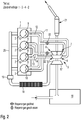
- Fig. 1 shows a first mode for a four-cylinder, inventive internal combustion engine 1.
- a fresh air is first promoted by an unnumbered intake system in a Ansauggeräuschdämpfer 16 and then passes through a compressor 17 of an exhaust gas turbocharger 3, from which the fresh air is compressed and heated.
- An inflow of fresh air is shown by an arrow in the direction of intake silencer 16.
- the heated fresh air is then cooled in a charge air cooler 18 and further promoted by a throttle valve 19 in an air collector 20 and promoted from there into four cylinders 2 of the internal combustion engine 1 and burned.
- Each cylinder 2 has two gas exchange exhaust valves 9, 10 which are numbered the same for each cylinder 2.
- each gas exchange outlet valve 9, 10 each have their own exhaust pipe 11, 12, 13, 14 is provided, wherein in each case an outlet gas exchange valve 9, 10 of two cylinders 2 on an exhaust pipe 11, 12, 13, 14 are interconnected and then in four exhaust gas inlets 4, 5, 6, 7 of an exhaust gas turbocharger 3 open.
- two cylinders 2 are combined to form a cylinder group.
- the cylinders 1 and 4 and the cylinders 2 and 3 (numbered according to the firing order).
- the summary is carried out according to a firing order of cylinder 1 to cylinder 3 to cylinder 4 to cylinder 2, with a uniform firing interval. In a different firing order, the cylinder summary is again such that a uniform firing interval is present.
- Each of the exhaust pipes 11, 12, 13, 14 is connected to a separate exhaust gas inlet 4, 5, 6, 7 in an unnumbered turbine housing of the exhaust gas turbocharger 3, in which a turbine 8 is rotatably mounted and drives the compressor 17, leading exhaust.
- the exhaust gas leaves the turbine housing through an unnumbered exhaust system in which an exhaust gas purification system 21 is arranged.
- the exiting exhaust gas is shown schematically by an arrow.
- each two cylinders 2 are combined to form a cylinder group and each exhaust gas inlet 4, 5, 6, 7, with a cylinder group through an exhaust pipe 11, 12, 13, 14 via one gas exchange outlet valve 9, 10 per cylinder 2 exhaust gas leader is connectable and the turbine 8 can be acted upon with exhaust gas every 180 ° crank angle.
- all gas exchange outlet valves 9, 10 are actuated at higher load or during full load operation of the internal combustion engine.
- shut-off elements 22 such. As flaps or rotating rollers are opened in this mode, so that a maximum amount of exhaust gas can drive the turbine 8 of the exhaust gas turbocharger 3.
- FIG. 2 shows a second mode for a four-cylinder internal combustion engine according to the invention 1.
- the second embodiment differs from the first embodiment in that the shut-off valves 22 in the exhaust pipes 12, 14 are closed. This means that the internal combustion engine is operated in a partial load operation.
- FIG. 3 shows a third operating mode for the four-cylinder internal combustion engine 1 according to the invention.
- a separate exhaust pipe 11, 12, 13, 14 is provided for each gas exchange outlet valve 9, 10, wherein in each case one exhaust gas exchange valve 9, 10 of two cylinders 2 to an exhaust pipe 11, 12, 13, 14 are interconnected and then open into four exhaust gas inlets 4, 5, 6, 7 of an exhaust gas turbocharger 3.
- two cylinders 2 are combined to form a cylinder group.
- the summary is carried out according to the firing order of cylinder 1 to cylinder 3 to cylinder 4 to cylinder 2, with a uniform firing interval.
- the third embodiment differs from the first two embodiments in that only two cylinders 2, namely the cylinders 1 and 4 (numbered according to the firing order) are operated.
- a method for operating the internal combustion engine 1 according to the invention can be represented, wherein at lower Load of the internal combustion engine 1 for a cylinder group both shut-off valves 22 are closed.
- the shut-off elements 22 can also be provided for the other cylinder group.
- FIG. 4 shows a fourth mode for the inventive four-cylinder internal combustion engine 1.
- the embodiment in FIG. 4 corresponds to the embodiment of Fig. 3 However, it differs from the first three embodiments in that switchable flood connections 15 are provided, which cancel the flow separation of the cylinder groups 1 and 4 as well as 2 and 3. As a result, the exhaust backpressure of the internal combustion engine 1 is advantageously further reduced to the level of a mono-scroll turbine.
- the turbine housing has two twin-scroll exhaust gas inlets whose exhaust gas separation reaches as far as the turbine runner.
- the floods by means of the flood connections 15 with each other gas leading can be connected to each other to further reduce the exhaust backpressure at high or full load of the internal combustion engine 1.
- the exhaust gas turbine 8 is preferably a so-called double turbine.
- the shutdown of the floods can basically be done via the shut-off elements 22.
- the use is in principle possible in in-line four-cylinder and in-line six-cylinder internal combustion engines, as well as in eight-cylinder and twelve-cylinder V engine engines with one turbocharger per cylinder bank.
- the invention advantageously allows the use of a sub-turbine (an axial section of the turbine 8) with better utilization of the exhaust pulse and the maintenance of flood separation and circuits for z.
- a sub-turbine an axial section of the turbine 8
- This can z.
- the turbine designed to be larger overall in order to reduce the back pressure in the rated power and at the same time to achieve a higher charging and efficiency in the partial load.
Landscapes
- Engineering & Computer Science (AREA)
- Chemical & Material Sciences (AREA)
- Combustion & Propulsion (AREA)
- Mechanical Engineering (AREA)
- General Engineering & Computer Science (AREA)
- Supercharger (AREA)
Abstract
Description
- Die Erfindung betrifft eine Brennkraftmaschine mit den Merkmalen aus dem Oberbegriff des Patentanspruchs 1 und Verfahren zum Betreiben der Brennkraftmaschine gemäß den Patentansprüchen 6 und 7.
- Zum technischen Umfeld wird beispielsweise auf die Europäische Patentschrift
EP 2 115 284 B1 hingewiesen. Aus dieser ist eine Brennkraftmaschine mit 8 Zylindern in V-Bauart, mit einer Abgasanlage mit einem ersten und einem zweiten Abgasturbolader bekannt, wobei von einem ersten, einem zweiten, einem dritten und einem vierten, in Reihe nebeneinander angeordneten Zylinder eine erste Zylinderbank und von einem fünften, einem sechsten, einem siebten und einem achten, in Reihe nebeneinander angeordneten Zylinder eine zweite, der ersten Zylinderbank gegenüberliegende Zylinderbank gebildet ist, wobei die Brennkraftmaschine von Zylinder zu Zylinder eine Zündfolge von 90° Kurbelwinkel aufweist, wobei die Abgasanlage einen ersten, einen zweiten, einen dritten und einen vierten Abgasstrang von den Zylindern zu den zwei Abgasturboladern aufweist, und wobei einem Abgasstrang jeweils zwei Zylinder und zwei Abgassträngen jeweils ein Abgasturbolader zugeordnet ist, wobei zwei, einem Abgasstrang zugeordnete Zylinder einen Zündabstand von 360° Kurbelwinkel aufweisen und dass der erste und der zweite, einem Abgasturbolader zugeordnete Abgasstrang eine um 180° Kurbelwinkel zueinander verschobene Zündfolge aufweist. - Weiter ist aus der europäischen Patentschrift
EP 0 247 631 B1 eine Auspuffanlage eines Verbrennungsmotors bekannt. Dieser weist auf: - Eine Mehrzahl von einander unabhängiger Passagen, die jeweils einzeln mit einer Austrittsöffnung eines Zylinders des Motors verbunden sind und zu einer Verbindungsstelle mehrerer voneinander unabhängiger Passagen führen, und mit
- wenigstens einer Verbindungspassage, die wenigstens zwei voneinander unabhängige Passagen an von der Verbindungsstelle stromauf gelegenen Stellen miteinander verbindet,
- wobei die Verbindungspassage wenigstens zwei Abzweigarme beinhaltet, die jeweils von einer unabhängigen Passage an einer der genannten Stellen abzweigen und an dieser Stelle in Richtung auf die Austrittsöffnung gerichtet sind, und
- in einem von der genannten Stelle stromab gelegenen Bereich der Äquivalenzdurchmesser der unabhängigen Passage geringer ist als stromauf an dieser Stelle.
- Weiter wird zum technischen Umfeld auf die Patentschrift Nr.
7000941 aus der Deutschen Demokratischen Republik hingewiesen, aus der eine Leitvorrichtung für radial beaufschlagte Turbinenräder bekannt ist. Es wird eine Leitvorrichtung beansprucht, für radial beaufschlagte Turbinenräder, insbesondere für heiße Gase, wobei diese mindestens einen axial zur Turbinenachse verschiebbaren Leitschaufelkranz umfasst und dieser Leitschaufelkranz wahlweise und wenigstens teilweise derart in den Druckmittelstrom vor der Laufschaufelung mindestens eines Turbinenrads einer Turbine hineingeschoben werden kann, dass dadurch eine Änderung der Durchflussbedingungen für das Druckmittel, je nach Form, Richtung und Durchflussquerschnitten der Leitschaufeln erfolgt, zum Zwecke, dadurch das Turbinenlaufrad mit nach Menge,
Druck- und Temperatur veränderlicher Druckmittelenergie zu beaufschlagen. - Eine Segmentturbine ist beispielsweise aus der französischen Patentanmeldung
FR 2 801 072 A1 - Eine Zwillingstromturbine ist beispielsweise aus der Deutschen Offenlegungsschrift
DE 10 2007 017 826 A1 bekannt. - Heutige bekannte Turbinen von Abgasturboladern mit variablem Abgas-Massenstrom sind typischerweise mit einem variablen Vorleitrad (VTG) ausgestattet und bisher nur für einflutige Turbinen ausgeführt. Aufgrund von erforderlichen Spielen der Leitschaufeln und deren Verstelleinrichtung, sind die ertragbaren Turbineneintrittstemperaturen von VTGs typischerweise niedriger als bei Turbinen mit fester Geometrie, insbesondere für Brennkraftmaschinen, die nach dem Ottoprinzip arbeiten. Ausführungen, die hohe Temperaturen vertragen sind wegen der erforderlichen hoch temperaturfesten Werkstoffe wesentlich teurer. Es existiert somit aktuell keine kostengünstige Lösung für einen variablen Massenstrom für zweiflutige Turbinen, auch Twin-Scroll-Turbinen genannt.
- Aufgabe der vorliegenden Erfindung ist es, eine kostengünstige Lösung für einen variablen Abgas-Massenstrom für zweiflutige Turbinen aufzuzeigen.
- Diese Aufgabe wird durch die Merkmale im kennzeichnenden Teil des Patentanspruchs 1 gelöst.
- Vorteilhafte Weiterbildungen der Erfindung sind in den Unteransprüchen beschrieben.
- Um sowohl eine Flutentrennung, als auch eine Zweipunkt-Variabilität des Abgas-Massenstroms zu ermöglichen, wird erfindungsgemäß eine Brennkraftmaschine mit einer Segmentturbine vorgeschlagen, deren Voluten zusätzlich eine axiale Trennwand aufweisen (Twin-Scroll) und die an die Auslasskanäle angeschlossen ist, wobei jeder Auslasskanal für ein Gaswechsel-Auslassventil vorgesehen ist. Es handelt sich somit um eine "segmentierte Zwillingsstromturbine".
- Unter einer segmentierten Zwillingsstromturbine wird eine Turbine eines Abgasturboladers verstanden, deren Turbinengehäuse über zwei weitgehend gegenüberliegende Twin-Scrolls verfügt. Gegenüber einem Twin-Scroll sind bei einer segmentierten Zwillingsstromturbine die Flutentrennung um 90° gedreht, d. h. die Trennwand erstreckt sich koaxial zu einer Drehachse der Turbine. Jeder Twin-Scroll leitet Abgas radial umlaufend auf das Turbinenrad, wobei die zwei Scrolls des ersten Twin-Scroll axial voneinander beabstandet sind und den Scrolls des zweiten Twin-Scroll gegenüber liegen. Somit bilden der erste Scroll des ersten Twin-Scrolls eine erste Abgaseintrittsebene auf das Turbinenrad und der zweite Scroll des zweiten Twin-Scrolls eine zweite, von der ersten Abgaseintrittsebene axial beabstandete zweite Abgaseintrittsebene auf das Turbinenrad. Alle vier Scrolls sind von dem Turbinengehäuse bis zum Turbinenrad vollständig voneinander getrennt. Eine gattungsgemäße segmentierte Zwillingstromturbine ist beispielsweise aus der deutschen Offenlegungsschrift
DE 10 2011 016 528 A1 bekannt. Dieses bekannte Turbinengehäuse weist jedoch keine Flutenverbindungen auf. - Das Abschalten der Fluten kann grundsätzlich über die Absperrorgane erfolgen. Als Absperrorgane können beispielsweise Klappen, Ventile oder Walzen zum Einsatz kommen, wie sie aus dem Stand der Technik bekannt sind. Der Einsatz ist prinzipiell bei Reihenvierzylinder-, und Reihensechszylinder-Brennkraftmaschinen, sowie bei Achtzylinder- und Zwölfzylinder-Brennkraftmaschinen mit V-Bauform mit je einem Turbolader pro Zylinderbank möglich.
- Die Erfindung ermöglicht die Nutzung einer Teilturbine mit besserer Ausnutzung des Abgasimpulses und der Aufrechterhaltung der Flutentrennung und auch Schaltungen für z. B. den Betrieb mit einem abgeschalteten Zylinder, sowie durch Umschalten die Nutzung der gesamten Turbine zur Erzielung der Nennleistung. Damit kann z. B. die Turbine insgesamt größer ausgelegt werden, um den Gegendruck in der Nennleistung zu reduzieren und gleichzeitig in der Teillast einen höheren Auflade- und Wirkungsgrad zu erreichen.
- Die Ausgestaltung gemäß Patentanspruch 2 ist für eine 6-Zylinder Brennkraftmaschine vorgesehen und kann ebenfalls für eine Zwölfzylinder-Brennkraftmaschine der V-Bauart eingesetzt werden.
- Die Ausgestaltung gemäß Patentanspruch 3 ist eine besonders bevorzugte Ausführungsvariante für die Zusammenschaltung der einzelnen Fluten für einen Volllastbetrieb der Brennkraftmaschine bei der der Abgasgegendruck in vorteilhafter Weise abgesenkt wird.
- Die Ausgestaltung gemäß Patentanspruch 4 ist ein besonders bevorzugtes Ausführungsbeispiel.
- Die Ausgestaltung gemäß Patentanspruch 5 ist eine bevorzugte Ausführungsvariante, wobei das Turbinenlaufrad aus zwei starr gekoppelten, axial zueinander angeordneten Turbinenlaufrädern besteht, die gemeinsam ein Verdichterrad des Abgasturboladers antreiben.
- Mit den erfindungsgemäßen Verfahren gemäß Patentanspruch 6 ist der Teillastbetrieb der Brennkraftmaschine darstellbar.
- Mit den erfindungsgemäßen Verfahren gemäß den Patentansprüchen 7 und 8 ist der Volllastbetrieb der Brennkraftmaschine bei geringstem Abgasgegendruck darstellbar.
- Im Folgenden ist die Erfindung anhand von vier Figuren näher erläutert.
- Figur 1
- zeigt schematisch eine vierzylindrige, erfindungsgemäße Brennkraftmaschine für eine erste Betriebsart.
- Figur 2
- zeigt schematisch eine vierzylindrige erfindungsgemäße Brennkraftmaschine für eine zweite Betriebsart.
- Figur 3
- zeigt schematisch eine vierzylindrige, erfindungsgemäße Brennkraftmaschine für eine dritte Betriebsart.
- Figur 4
- zeigt schematisch eine vierzylindrige, erfindungsgemäße Brennkraftmaschine für eine vierte Betriebsart.
- Im Folgenden gelten in den
Figuren 1 bis 4 für gleiche Bauelemente die gleichen Bezugsziffern. -
Fig. 1 zeigt eine erste Betriebsart für eine vierzylindrige, erfindungsgemäße Brennkraftmaschine 1. Eine Frischluft wird durch ein nicht beziffertes Ansaugsystem zuerst in einen Ansauggeräuschdämpfer 16 gefördert und durchläuft anschließend einen Verdichter 17 eines Abgasturboladers 3, von dem die Frischluft verdichtet und aufgeheizt wird. Ein Einströmen der Frischluft ist durch einen Pfeil in Richtung Ansauggeräuschdämpfer 16 dargestellt. Die aufgeheizte Frischluft wird anschließend in einem Ladeluftkühler 18 gekühlt und weiter durch eine Drosselklappe 19 in einen Luftsammler 20 gefördert und von dort in vier Zylinder 2 der Brennkraftmaschine 1 gefördert und verbrannt. - Jeder Zylinder 2 verfügt über zwei Gaswechsel-Auslassventile 9, 10 die für jeden Zylinder 2 gleich beziffert sind. Für jedes Gaswechsel-Auslassventil 9, 10 ist jeweils ein eigenes Abgasrohr 11, 12, 13, 14 vorgesehen, wobei jeweils ein Auslass-Gaswechselventil 9, 10 von zwei Zylindern 2 auf ein Abgasrohr 11, 12, 13, 14 zusammengeschalten sind und dann in vier Abgaseinlässe 4, 5, 6, 7 eines Abgasturboladers 3 münden. Somit werden jeweils zwei Zylinder 2 zu einer Zylindergruppe zusammengefasst. Im vorliegenden Ausführungsbeispiel die Zylinder 1 und 4 und die Zylinder 2 und 3 (gemäß der Zündreihenfolge nummeriert). Die Zusammenfassung erfolgt entsprechend einer Zündreihenfolge von Zylinder 1 zu Zylinder 3 zu Zylinder 4 zu Zylinder 2, mit einem gleichmäßigen Zündabstand. Bei einer abweichenden Zündreihenfolge erfolgt die Zylinderzusammenfassung wieder derart, dass ein gleichmäßiger Zündabstand vorliegt.
- Jedes der Abgasrohre 11, 12, 13, 14 ist mit einem separaten Abgaseinlass 4, 5, 6, 7 in einem nicht bezifferten Turbinengehäuse des Abgasturboladers 3, in dem eine Turbine 8 drehbar gelagert ist und den Verdichter 17 antreibt, Abgas führend verbunden. Das Abgas verlässt das Turbinengehäuse durch einen nicht bezifferten Abgasstrang in dem eine Abgasreinigungsanlage 21 angeordnet ist. Das austretende Abgas ist mit einem Pfeil schematisch dargestellt.
- Zusammengefasst kann gesagt werden, dass je zwei Zylinder 2 zu einer Zylindergruppe zusammengefasst sind und jeder Abgaseinlass 4, 5, 6, 7, mit einer Zylindergruppe durch ein Abgasrohr 11, 12, 13, 14 über je ein Gaswechselauslassventil 9, 10 je Zylinder 2 Abgas führend verbindbar ist und die Turbine 8 alle 180° Kurbelwinkel mit Abgas beaufschlagbar ist.
- In dem vorliegenden Ausführungsbeispiel werden bei höherer Last oder beim Volllastbetrieb der Brennkraftmaschine sämtliche Gaswechselauslassventile 9, 10 betätigt. In den Abgasrohren 12 und 14 befindliche Absperrorgane 22, wie z. B. Klappen oder Drehwalzen, werden bei dieser Betriebsart geöffnet, damit eine maximale Abgasmenge die Turbine 8 des Abgasturboladers 3 antreiben kann.
- Die grundsätzliche Funktion der erfindungsgemäßen Brennkraftmaschine 1 gilt auch für die weiteren
Figuren 2 bis 4 , und wird bei denen nicht nochmals erörtert. -
Figur 2 zeigt eine zweite Betriebsart für eine erfindungsgemäße, vierzylindrige Brennkraftmaschine 1. Das zweite Ausführungsbeispiel unterscheidet sich vom ersten Ausführungsbeispiel dadurch, dass die Absperrorgane 22 in den Abgasrohren 12, 14 geschlossen sind. Dies bedeutet, dass die Brennkraftmaschine in einem Teillastbetrieb betrieben wird. -
Figur 3 zeigt eine dritte Betriebsart für die erfindungsgemäße, vierzylindrige Brennkraftmaschine 1. Auch hier ist für jedes Gaswechsel-Auslassventil 9, 10 ist jeweils ein eigenes Abgasrohr 11, 12, 13, 14 vorgesehen, wobei jeweils ein Auslass-Gaswechselventil 9, 10 von zwei Zylindern 2 auf ein Abgasrohr 11, 12, 13, 14 zusammengeschalten sind und dann in vier Abgaseinlässe 4, 5, 6, 7 eines Abgasturboladers 3 münden. Somit werden jeweils zwei Zylinder 2 zu einer Zylindergruppe zusammengefasst. In diesem vorliegenden Ausführungsbeispiel die Zylinder 2 und 3 und die Zylinder 1 und 4. Auch hier erfolgt die Zusammenfassung entsprechend der Zündreihenfolge von Zylinder 1 zu Zylinder 3 zu Zylinder 4 zu Zylinder 2, mit einem gleichmäßigen Zündabstand. Bei einer abweichenden Zündreihenfolge erfolgt die Zylinderzusammenfassung wieder derart, dass ein gleichmäßiger Zündabstand vorliegt. Das dritte Ausführungsbeispiel unterscheidet sich von den ersten zwei Ausführungsbeispielen dadurch, dass nur noch zwei Zylinder 2, nämlich die Zylinder 1 und 4 (gemäß der Zündreihenfolge nummeriert) betreiben werden. Mit dieser Konfiguration, auch Zylinderabschaltung genannt, ist ein Verfahren zum Betreiben der erfindungsgemäßen Brennkraftmaschine 1 darstellbar, wobei bei niedriger Last der Brennkraftmaschine 1 für eine Zylindergruppe beide Absperrorgane 22 geschlossen werden. Die Absperrorgane 22 können auch für die andere Zylindergruppe vorgesehen werden. -
Figur 4 zeigt eine vierte Betriebsart für die erfindungsgemäße, vierzylindrige Brennkraftmaschine 1. Das Ausführungsbeispiel inFigur 4 entspricht dem Ausführungsbeispiel ausFig. 3 , unterscheidet sich jedoch von den ersten drei Ausführungsbeispielen dadurch, dass schaltbare Flutenverbindungen 15 vorgesehen sind, die die Flutentrennung der Zylindergruppen 1 und 4 sowie 2 und 3 aufheben. Hierdurch wird der Abgasgegendruck der Brennkraftmaschine 1 in vorteilhafter Weise nochmals weiter auf das Niveau einer Mono-Scroll Turbine reduziert. - Für alle
Figuren 1 bis 4 gilt, dass das Turbinengehäuse über zwei Twin-Scroll Abgaseinlässe verfügt, deren Abgastrennung bis an das Turbinenlaufrad reicht. Jedoch können die Fluten mittels der Flutenverbindungen 15 miteinander Gas führend miteinander verbunden werden, um bei hoher oder Volllast der Brennkraftmaschine 1 den Abgasgegendruck weiter abzusenken. Bevorzugt ist hierbei die Abgasturbine 8 eine sogenannte Doppelturbine. - Das Abschalten der Fluten kann grundsätzlich über die Absperrorgane 22 erfolgen. Der Einsatz ist prinzipiell bei Reihenvierzylinder-, und Reihensechszylinder-Brennkraftmaschinen, sowie bei Achtzylinder- und Zwölfzylinder-Brennkraftmaschinen mit V-Bauform mit je einem Turbolader pro Zylinderbank möglich.
- Die Erfindung ermöglicht in vorteilhafter Weise die Nutzung einer Teilturbine (ein axialer Abschnitt der Turbine 8) mit besserer Ausnutzung des Abgasimpulses und der Aufrechterhaltung der Flutentrennung und auch Schaltungen für z. B. den Betrieb mit einem abgeschalteten Zylinder, sowie durch Umschalten die Nutzung der gesamten Turbine zur Erzielung der Nennleistung. Damit kann z. B. die Turbine insgesamt größer ausgelegt werden, um den Gegendruck in der Nennleistung zu reduzieren und gleichzeitig in der Teillast einen höheren Auflade- und Wirkungsgrad zu erreichen.
-
- 1
- Brennkraftmaschine
- 2
- Zylinder
- 3
- Abgasturbolader
- 4
- Abgaseinlass
- 5.
- Abgaseinlass
- 6.
- Abgaseinlass
- 7.
- Abgaseinlass
- 8.
- Abgasturbine
- 9.
- Gaswechsel-Auslassventil
- 10.
- Gaswechsel-Auslassventil
- 11.
- Abgasrohr
- 12.
- Abgasrohr
- 13.
- Abgasrohr
- 14.
- Abgasrohr
- 15.
- Flutenverbindung
- 16.
- Ansauggeräuschdämpfer
- 17.
- Verdichter
- 18.
- Ladeluftkühler
- 19.
- Drosselklappe
- 20.
- Luftsammler
- 21.
- Abgasreinigungsanlage
- 22.
- Absperrorgan
Claims (8)
- Brennkraftmaschine (1) mit zumindest vier Zylindern (2) und mit einem Abgasturbolader (3) mit einem Turbinengehäuse mit vier Abgaseinlässen (4, 5, 6, 7), in dem eine Abgasturbine (8) drehbar angeordnet ist, wobei jeder Zylinder (2) zwei Gaswechsel-Auslassventile (9, 10) aufweist,
dadurch gekennzeichnet, dass je zwei Zylinder (2) zu einer Zylindergruppe zusammengefasst sind und jeder Abgaseinlass (4, 5, 6, 7) mit einer Zylindergruppe durch ein Abgasrohr (11, 12, 13, 14) über je ein Gaswechsel-Auslassventil (9, 10) je Zylinder (2) Abgas führend verbindbar ist und die Abgasturbine (8) alle 180° Kurbelwinkel mit Abgas beaufschlagbar ist, wobei ein gemeinsames Abgasrohr (11, 12, 13, 14) je Zylindergruppe oder beide gemeinsamen Abgasrohre (11, 12, 13, 14) einer Zylindergruppe ein Absperrorgan (22) aufweist. - Brennkraftmaschine nach Patentanspruch 1, wobei die Brennkraftmaschine sechs Zylinder aufweist,
dadurch gekennzeichnet, dass je drei Zylinder (2) zu einer Zylindergruppe zusammengefasst sind und jeder Abgaseinlass (4, 5, 6, 7) mit einer Zylindergruppe durch ein Abgasrohr (11, 12, 13, 14) über je ein Gaswechsel-Auslassventil (9, 10) je Zylinder (2) Abgas führend verbindbar ist und die Abgasturbine (8) alle 120° Kurbelwinkel mit Abgas beaufschlagbar ist, wobei ein gemeinsames Abgasrohr (11, 12, 13, 14) je Zylindergruppe oder beide gemeinsamen Abgasrohre (11, 12, 13, 14) einer Zylindergruppe ein Absperrorgan (22) aufweist. - Brennkraftmaschine nach einem der Patentansprüche 1 oder 2,
dadurch gekennzeichnet, dass das Abgas einer Zylindergruppe mit dem Abgas der anderen Zylindergruppe über eine Flutenverbindung (15) (11, 12, 13, 14) verbindbar ist. - Brennkraftmaschine nach einem der Patentansprüche 1 bis 3,
dadurch gekennzeichnet, dass das Turbinengehäuse über zwei Twin-Scroll Abgaseinlässe verfügt. - Brennkraftmaschine nach einem der Patentansprüche 1 bis 3,
dadurch gekennzeichnet, dass die Abgasturbine (8) eine Doppelturbine ist. - Verfahren zum Betreiben einer Brennkraftmaschine nach Patentanspruch 1 oder 2,
dadurch gekennzeichnet, dass bei niedriger Last der Brennkraftmaschine (1) die Absperrorgane (22) geschlossen werden. - Verfahren zum Betreiben einer Brennkraftmaschine nach Patentanspruch 3,
dadurch gekennzeichnet, dass bei hoher Last der Brennkraftmaschine die Absperrorgane (22) geöffnet werden. - Verfahren zum Betreiben einer Brennkraftmaschine nach Patentanspruch 3,
dadurch gekennzeichnet, dass bei hoher Last der Brennkraftmaschine die Flutenverbindungen (15) geöffnet werden.
Applications Claiming Priority (1)
| Application Number | Priority Date | Filing Date | Title |
|---|---|---|---|
| DE102017220192.4A DE102017220192A1 (de) | 2017-11-14 | 2017-11-14 | Brennkraftmaschine und Verfahren zum Betreiben der Brennkraftmaschine |
Publications (2)
| Publication Number | Publication Date |
|---|---|
| EP3483408A1 true EP3483408A1 (de) | 2019-05-15 |
| EP3483408B1 EP3483408B1 (de) | 2021-03-31 |
Family
ID=63579260
Family Applications (1)
| Application Number | Title | Priority Date | Filing Date |
|---|---|---|---|
| EP18194391.1A Active EP3483408B1 (de) | 2017-11-14 | 2018-09-14 | Brennkraftmaschine und verfahren zum betreiben der brennkraftmaschine |
Country Status (2)
| Country | Link |
|---|---|
| EP (1) | EP3483408B1 (de) |
| DE (1) | DE102017220192A1 (de) |
Citations (3)
| Publication number | Priority date | Publication date | Assignee | Title |
|---|---|---|---|---|
| JPS6220631A (ja) * | 1985-07-19 | 1987-01-29 | Mazda Motor Corp | 排気タ−ボ過給機付エンジン |
| DE102012023118A1 (de) * | 2012-11-27 | 2014-05-28 | Daimler Ag | Verbrennungskraftmaschine für einen Kraftwagen |
| DE102014016877A1 (de) * | 2014-11-15 | 2016-05-19 | Audi Ag | Verfahren zum Betreiben einer Brennkraftmaschine sowie entsprechende Brennkraftmaschine |
Family Cites Families (9)
| Publication number | Priority date | Publication date | Assignee | Title |
|---|---|---|---|---|
| DE1004861B (de) * | 1955-02-03 | 1957-03-21 | Maschf Augsburg Nuernberg Ag | Mehrzylindrige, schlitzgesteuerte Zweitakt-Brennkraftmaschine mit Abgasturboaufladung |
| US4813232A (en) | 1986-05-30 | 1989-03-21 | Mazda Motor Corporation | Exhaust device for internal combustion engine |
| DE19918232C2 (de) * | 1999-04-22 | 2001-03-01 | Daimler Chrysler Ag | Mehrzylindriger Verbrennungsmotor mit einem Abgasturbolader |
| FR2801072B1 (fr) | 1999-11-17 | 2002-11-08 | Renault | Turbocompresseur comportant des entrees de turbine alignees selon un plan radial |
| FR2844552B1 (fr) * | 2002-09-16 | 2006-05-26 | Renault Sa | Moteur suralimente comportant une turbine multi-volutes |
| DE102007006699A1 (de) | 2007-02-10 | 2008-08-14 | Bayerische Motoren Werke Aktiengesellschaft | Abgasanlage für eine Brennkraftmaschine |
| DE102007017826B4 (de) | 2007-04-16 | 2010-11-04 | Continental Automotive Gmbh | Abgasturbolader |
| DE102011016528A1 (de) | 2011-04-08 | 2012-01-19 | Daimler Ag | Turbine für einen Abgasturbolader |
| EP2647808B1 (de) * | 2012-04-05 | 2015-12-09 | Universität Stuttgart | Abgastrakt für einen Verbrennungsmotor |
-
2017
- 2017-11-14 DE DE102017220192.4A patent/DE102017220192A1/de not_active Withdrawn
-
2018
- 2018-09-14 EP EP18194391.1A patent/EP3483408B1/de active Active
Patent Citations (3)
| Publication number | Priority date | Publication date | Assignee | Title |
|---|---|---|---|---|
| JPS6220631A (ja) * | 1985-07-19 | 1987-01-29 | Mazda Motor Corp | 排気タ−ボ過給機付エンジン |
| DE102012023118A1 (de) * | 2012-11-27 | 2014-05-28 | Daimler Ag | Verbrennungskraftmaschine für einen Kraftwagen |
| DE102014016877A1 (de) * | 2014-11-15 | 2016-05-19 | Audi Ag | Verfahren zum Betreiben einer Brennkraftmaschine sowie entsprechende Brennkraftmaschine |
Also Published As
| Publication number | Publication date |
|---|---|
| DE102017220192A1 (de) | 2019-05-16 |
| EP3483408B1 (de) | 2021-03-31 |
Similar Documents
| Publication | Publication Date | Title |
|---|---|---|
| EP1275832B1 (de) | Vorrichtung zur mehrstufigen Aufladung einer Brennkraftmaschine | |
| DE102016201464B4 (de) | Aufgeladene Brennkraftmaschine mit Abgasturboaufladung und Verfahren zum Betreiben einer derartigen Brennkraftmaschine | |
| DE10060690A1 (de) | Geregelte 2-stufige Aufladung am V-Motor | |
| DE102007046656B4 (de) | Verfahren zum Betreiben einer Brennkraftmaschine, Brennkraftmaschine | |
| DE102018215119B3 (de) | V8-Cross-Plane-Brennkraftmaschine und Betriebsverfahren | |
| DE102014208703A1 (de) | Abgasturboaufgeladene Brennkraftmaschine mit mindestens zwei Turbinen und Verfahren zum Betreiben einer derartigen Brennkraftmaschine | |
| DE3932721C1 (en) | Supercharged IC engine with turbo drive - has two-stage turbine with partial by=pass to control rotor speed | |
| EP3483407B1 (de) | Brennkraftmaschine und verfahren zum betreiben der brennkraftmaschine | |
| DE102008049091A1 (de) | Verfahren zum Betreiben einer Brennkraftmaschine mit acht Zylindern und Brennkraftmaschine | |
| DE102004038172A1 (de) | Brennkraftmaschine | |
| EP3483408B1 (de) | Brennkraftmaschine und verfahren zum betreiben der brennkraftmaschine | |
| DE102006042464A1 (de) | Verbrennungsmotor mit Abgasturboladeranordnung und Verfahren zum Betreiben eines Verbrennungsmotors und Abgasturboladeranordnung | |
| EP3642463B1 (de) | Brennkraftmaschine | |
| DE102018205768B3 (de) | Brennkraftmaschine mit einer Abgasanlage | |
| DE102018005460B3 (de) | Verbrennungskraftmaschine für ein Kraftfahrzeug, insbesondere für einen Kraftwagen, Verfahren zum Betreiben einer solchen Verbrennungskraftmaschine sowie Kraftfahrzeug mit einer solchen Verbrennungskraftmaschine | |
| DE102012103013B4 (de) | Brennkraftmaschine mit Abgasturbolader | |
| DE3601700A1 (de) | Mehrzylindrige brennkraftmaschine mit kraftstoffeinspritzung, insbesondere turbomotor | |
| WO2019201549A1 (de) | Brennkraftmaschine mit einer abgasanlage | |
| DE2948089A1 (de) | Turbolader fuer brennkraftmaschinen, insbesondere mehrflutiger abgasturbolader fuer motoren von kraftfahrzeugen | |
| DE102006047322A1 (de) | Verbrennungsmotor mit Abgasturboladeranordnung | |
| DE102016102222B4 (de) | Aufgeladene Brennkraftmaschine | |
| DE102013216608B4 (de) | Abgasturboaufgeladene Brennkraftmaschine umfassend einen Verdichter mit zwei Laufrädern | |
| DE102013003067B4 (de) | Verfahren zum Betreiben einer Brennkraftmaschine sowie entsprechende Brennkraftmaschine | |
| DE102018205770B4 (de) | Brennkraftmaschine mit einer Abgasanlage | |
| DE4330525A1 (de) | Brennkraftmaschine mit variabler Aufladung |
Legal Events
| Date | Code | Title | Description |
|---|---|---|---|
| PUAI | Public reference made under article 153(3) epc to a published international application that has entered the european phase |
Free format text: ORIGINAL CODE: 0009012 |
|
| STAA | Information on the status of an ep patent application or granted ep patent |
Free format text: STATUS: THE APPLICATION HAS BEEN PUBLISHED |
|
| AK | Designated contracting states |
Kind code of ref document: A1 Designated state(s): AL AT BE BG CH CY CZ DE DK EE ES FI FR GB GR HR HU IE IS IT LI LT LU LV MC MK MT NL NO PL PT RO RS SE SI SK SM TR |
|
| AX | Request for extension of the european patent |
Extension state: BA ME |
|
| STAA | Information on the status of an ep patent application or granted ep patent |
Free format text: STATUS: REQUEST FOR EXAMINATION WAS MADE |
|
| 17P | Request for examination filed |
Effective date: 20190524 |
|
| RBV | Designated contracting states (corrected) |
Designated state(s): AL AT BE BG CH CY CZ DE DK EE ES FI FR GB GR HR HU IE IS IT LI LT LU LV MC MK MT NL NO PL PT RO RS SE SI SK SM TR |
|
| STAA | Information on the status of an ep patent application or granted ep patent |
Free format text: STATUS: EXAMINATION IS IN PROGRESS |
|
| 17Q | First examination report despatched |
Effective date: 20200708 |
|
| GRAP | Despatch of communication of intention to grant a patent |
Free format text: ORIGINAL CODE: EPIDOSNIGR1 |
|
| STAA | Information on the status of an ep patent application or granted ep patent |
Free format text: STATUS: GRANT OF PATENT IS INTENDED |
|
| INTG | Intention to grant announced |
Effective date: 20201215 |
|
| GRAS | Grant fee paid |
Free format text: ORIGINAL CODE: EPIDOSNIGR3 |
|
| GRAA | (expected) grant |
Free format text: ORIGINAL CODE: 0009210 |
|
| STAA | Information on the status of an ep patent application or granted ep patent |
Free format text: STATUS: THE PATENT HAS BEEN GRANTED |
|
| AK | Designated contracting states |
Kind code of ref document: B1 Designated state(s): AL AT BE BG CH CY CZ DE DK EE ES FI FR GB GR HR HU IE IS IT LI LT LU LV MC MK MT NL NO PL PT RO RS SE SI SK SM TR |
|
| REG | Reference to a national code |
Ref country code: GB Ref legal event code: FG4D Free format text: NOT ENGLISH Ref country code: CH Ref legal event code: EP |
|
| REG | Reference to a national code |
Ref country code: AT Ref legal event code: REF Ref document number: 1377181 Country of ref document: AT Kind code of ref document: T Effective date: 20210415 |
|
| REG | Reference to a national code |
Ref country code: DE Ref legal event code: R096 Ref document number: 502018004503 Country of ref document: DE |
|
| REG | Reference to a national code |
Ref country code: IE Ref legal event code: FG4D Free format text: LANGUAGE OF EP DOCUMENT: GERMAN |
|
| REG | Reference to a national code |
Ref country code: LT Ref legal event code: MG9D |
|
| PG25 | Lapsed in a contracting state [announced via postgrant information from national office to epo] |
Ref country code: FI Free format text: LAPSE BECAUSE OF FAILURE TO SUBMIT A TRANSLATION OF THE DESCRIPTION OR TO PAY THE FEE WITHIN THE PRESCRIBED TIME-LIMIT Effective date: 20210331 Ref country code: HR Free format text: LAPSE BECAUSE OF FAILURE TO SUBMIT A TRANSLATION OF THE DESCRIPTION OR TO PAY THE FEE WITHIN THE PRESCRIBED TIME-LIMIT Effective date: 20210331 Ref country code: BG Free format text: LAPSE BECAUSE OF FAILURE TO SUBMIT A TRANSLATION OF THE DESCRIPTION OR TO PAY THE FEE WITHIN THE PRESCRIBED TIME-LIMIT Effective date: 20210630 Ref country code: NO Free format text: LAPSE BECAUSE OF FAILURE TO SUBMIT A TRANSLATION OF THE DESCRIPTION OR TO PAY THE FEE WITHIN THE PRESCRIBED TIME-LIMIT Effective date: 20210630 |
|
| PG25 | Lapsed in a contracting state [announced via postgrant information from national office to epo] |
Ref country code: RS Free format text: LAPSE BECAUSE OF FAILURE TO SUBMIT A TRANSLATION OF THE DESCRIPTION OR TO PAY THE FEE WITHIN THE PRESCRIBED TIME-LIMIT Effective date: 20210331 Ref country code: LV Free format text: LAPSE BECAUSE OF FAILURE TO SUBMIT A TRANSLATION OF THE DESCRIPTION OR TO PAY THE FEE WITHIN THE PRESCRIBED TIME-LIMIT Effective date: 20210331 Ref country code: SE Free format text: LAPSE BECAUSE OF FAILURE TO SUBMIT A TRANSLATION OF THE DESCRIPTION OR TO PAY THE FEE WITHIN THE PRESCRIBED TIME-LIMIT Effective date: 20210331 |
|
| REG | Reference to a national code |
Ref country code: NL Ref legal event code: MP Effective date: 20210331 |
|
| PG25 | Lapsed in a contracting state [announced via postgrant information from national office to epo] |
Ref country code: CZ Free format text: LAPSE BECAUSE OF FAILURE TO SUBMIT A TRANSLATION OF THE DESCRIPTION OR TO PAY THE FEE WITHIN THE PRESCRIBED TIME-LIMIT Effective date: 20210331 Ref country code: EE Free format text: LAPSE BECAUSE OF FAILURE TO SUBMIT A TRANSLATION OF THE DESCRIPTION OR TO PAY THE FEE WITHIN THE PRESCRIBED TIME-LIMIT Effective date: 20210331 Ref country code: LT Free format text: LAPSE BECAUSE OF FAILURE TO SUBMIT A TRANSLATION OF THE DESCRIPTION OR TO PAY THE FEE WITHIN THE PRESCRIBED TIME-LIMIT Effective date: 20210331 Ref country code: NL Free format text: LAPSE BECAUSE OF FAILURE TO SUBMIT A TRANSLATION OF THE DESCRIPTION OR TO PAY THE FEE WITHIN THE PRESCRIBED TIME-LIMIT Effective date: 20210331 Ref country code: SM Free format text: LAPSE BECAUSE OF FAILURE TO SUBMIT A TRANSLATION OF THE DESCRIPTION OR TO PAY THE FEE WITHIN THE PRESCRIBED TIME-LIMIT Effective date: 20210331 |
|
| PG25 | Lapsed in a contracting state [announced via postgrant information from national office to epo] |
Ref country code: SK Free format text: LAPSE BECAUSE OF FAILURE TO SUBMIT A TRANSLATION OF THE DESCRIPTION OR TO PAY THE FEE WITHIN THE PRESCRIBED TIME-LIMIT Effective date: 20210331 Ref country code: RO Free format text: LAPSE BECAUSE OF FAILURE TO SUBMIT A TRANSLATION OF THE DESCRIPTION OR TO PAY THE FEE WITHIN THE PRESCRIBED TIME-LIMIT Effective date: 20210331 Ref country code: PT Free format text: LAPSE BECAUSE OF FAILURE TO SUBMIT A TRANSLATION OF THE DESCRIPTION OR TO PAY THE FEE WITHIN THE PRESCRIBED TIME-LIMIT Effective date: 20210802 Ref country code: PL Free format text: LAPSE BECAUSE OF FAILURE TO SUBMIT A TRANSLATION OF THE DESCRIPTION OR TO PAY THE FEE WITHIN THE PRESCRIBED TIME-LIMIT Effective date: 20210331 Ref country code: IS Free format text: LAPSE BECAUSE OF FAILURE TO SUBMIT A TRANSLATION OF THE DESCRIPTION OR TO PAY THE FEE WITHIN THE PRESCRIBED TIME-LIMIT Effective date: 20210731 |
|
| REG | Reference to a national code |
Ref country code: DE Ref legal event code: R097 Ref document number: 502018004503 Country of ref document: DE |
|
| PG25 | Lapsed in a contracting state [announced via postgrant information from national office to epo] |
Ref country code: AL Free format text: LAPSE BECAUSE OF FAILURE TO SUBMIT A TRANSLATION OF THE DESCRIPTION OR TO PAY THE FEE WITHIN THE PRESCRIBED TIME-LIMIT Effective date: 20210331 Ref country code: DK Free format text: LAPSE BECAUSE OF FAILURE TO SUBMIT A TRANSLATION OF THE DESCRIPTION OR TO PAY THE FEE WITHIN THE PRESCRIBED TIME-LIMIT Effective date: 20210331 Ref country code: ES Free format text: LAPSE BECAUSE OF FAILURE TO SUBMIT A TRANSLATION OF THE DESCRIPTION OR TO PAY THE FEE WITHIN THE PRESCRIBED TIME-LIMIT Effective date: 20210331 |
|
| PLBE | No opposition filed within time limit |
Free format text: ORIGINAL CODE: 0009261 |
|
| STAA | Information on the status of an ep patent application or granted ep patent |
Free format text: STATUS: NO OPPOSITION FILED WITHIN TIME LIMIT |
|
| 26N | No opposition filed |
Effective date: 20220104 |
|
| REG | Reference to a national code |
Ref country code: CH Ref legal event code: PL |
|
| REG | Reference to a national code |
Ref country code: BE Ref legal event code: MM Effective date: 20210930 |
|
| PG25 | Lapsed in a contracting state [announced via postgrant information from national office to epo] |
Ref country code: IS Free format text: LAPSE BECAUSE OF FAILURE TO SUBMIT A TRANSLATION OF THE DESCRIPTION OR TO PAY THE FEE WITHIN THE PRESCRIBED TIME-LIMIT Effective date: 20210731 Ref country code: MC Free format text: LAPSE BECAUSE OF FAILURE TO SUBMIT A TRANSLATION OF THE DESCRIPTION OR TO PAY THE FEE WITHIN THE PRESCRIBED TIME-LIMIT Effective date: 20210331 |
|
| PG25 | Lapsed in a contracting state [announced via postgrant information from national office to epo] |
Ref country code: LU Free format text: LAPSE BECAUSE OF NON-PAYMENT OF DUE FEES Effective date: 20210914 Ref country code: IE Free format text: LAPSE BECAUSE OF NON-PAYMENT OF DUE FEES Effective date: 20210914 Ref country code: BE Free format text: LAPSE BECAUSE OF NON-PAYMENT OF DUE FEES Effective date: 20210930 |
|
| PG25 | Lapsed in a contracting state [announced via postgrant information from national office to epo] |
Ref country code: LI Free format text: LAPSE BECAUSE OF NON-PAYMENT OF DUE FEES Effective date: 20210930 Ref country code: CH Free format text: LAPSE BECAUSE OF NON-PAYMENT OF DUE FEES Effective date: 20210930 |
|
| P01 | Opt-out of the competence of the unified patent court (upc) registered |
Effective date: 20230502 |
|
| PG25 | Lapsed in a contracting state [announced via postgrant information from national office to epo] |
Ref country code: CY Free format text: LAPSE BECAUSE OF FAILURE TO SUBMIT A TRANSLATION OF THE DESCRIPTION OR TO PAY THE FEE WITHIN THE PRESCRIBED TIME-LIMIT Effective date: 20210331 |
|
| PG25 | Lapsed in a contracting state [announced via postgrant information from national office to epo] |
Ref country code: HU Free format text: LAPSE BECAUSE OF FAILURE TO SUBMIT A TRANSLATION OF THE DESCRIPTION OR TO PAY THE FEE WITHIN THE PRESCRIBED TIME-LIMIT; INVALID AB INITIO Effective date: 20180914 Ref country code: GR Free format text: LAPSE BECAUSE OF FAILURE TO SUBMIT A TRANSLATION OF THE DESCRIPTION OR TO PAY THE FEE WITHIN THE PRESCRIBED TIME-LIMIT Effective date: 20210331 |
|
| PG25 | Lapsed in a contracting state [announced via postgrant information from national office to epo] |
Ref country code: MK Free format text: LAPSE BECAUSE OF FAILURE TO SUBMIT A TRANSLATION OF THE DESCRIPTION OR TO PAY THE FEE WITHIN THE PRESCRIBED TIME-LIMIT Effective date: 20210331 |
|
| PG25 | Lapsed in a contracting state [announced via postgrant information from national office to epo] |
Ref country code: MT Free format text: LAPSE BECAUSE OF FAILURE TO SUBMIT A TRANSLATION OF THE DESCRIPTION OR TO PAY THE FEE WITHIN THE PRESCRIBED TIME-LIMIT Effective date: 20210331 |
|
| REG | Reference to a national code |
Ref country code: AT Ref legal event code: MM01 Ref document number: 1377181 Country of ref document: AT Kind code of ref document: T Effective date: 20230914 |
|
| PG25 | Lapsed in a contracting state [announced via postgrant information from national office to epo] |
Ref country code: AT Free format text: LAPSE BECAUSE OF NON-PAYMENT OF DUE FEES Effective date: 20230914 |
|
| PG25 | Lapsed in a contracting state [announced via postgrant information from national office to epo] |
Ref country code: AT Free format text: LAPSE BECAUSE OF NON-PAYMENT OF DUE FEES Effective date: 20230914 |
|
| PGFP | Annual fee paid to national office [announced via postgrant information from national office to epo] |
Ref country code: DE Payment date: 20250909 Year of fee payment: 8 |
|
| PGFP | Annual fee paid to national office [announced via postgrant information from national office to epo] |
Ref country code: GB Payment date: 20250923 Year of fee payment: 8 |
|
| PGFP | Annual fee paid to national office [announced via postgrant information from national office to epo] |
Ref country code: FR Payment date: 20250924 Year of fee payment: 8 |
|
| PG25 | Lapsed in a contracting state [announced via postgrant information from national office to epo] |
Ref country code: TR Free format text: LAPSE BECAUSE OF FAILURE TO SUBMIT A TRANSLATION OF THE DESCRIPTION OR TO PAY THE FEE WITHIN THE PRESCRIBED TIME-LIMIT Effective date: 20210331 |
|
| PGFP | Annual fee paid to national office [announced via postgrant information from national office to epo] |
Ref country code: IT Payment date: 20250930 Year of fee payment: 8 |
|
| PGFP | Annual fee paid to national office [announced via postgrant information from national office to epo] |
Ref country code: AT Payment date: 20260410 Year of fee payment: 5 |