EP3483066B1 - Landesysteme und verfahren für unbemanntes luftfahrzeug - Google Patents
Landesysteme und verfahren für unbemanntes luftfahrzeug Download PDFInfo
- Publication number
- EP3483066B1 EP3483066B1 EP18201103.1A EP18201103A EP3483066B1 EP 3483066 B1 EP3483066 B1 EP 3483066B1 EP 18201103 A EP18201103 A EP 18201103A EP 3483066 B1 EP3483066 B1 EP 3483066B1
- Authority
- EP
- European Patent Office
- Prior art keywords
- landing
- uavs
- control unit
- uav
- destination
- Prior art date
- Legal status (The legal status is an assumption and is not a legal conclusion. Google has not performed a legal analysis and makes no representation as to the accuracy of the status listed.)
- Active
Links
Images

Classifications
-
- G—PHYSICS
- G05—CONTROLLING; REGULATING
- G05D—SYSTEMS FOR CONTROLLING OR REGULATING NON-ELECTRIC VARIABLES
- G05D1/00—Control of position, course, altitude or attitude of land, water, air or space vehicles, e.g. using automatic pilots
- G05D1/0011—Control of position, course, altitude or attitude of land, water, air or space vehicles, e.g. using automatic pilots associated with a remote control arrangement
- G05D1/0027—Control of position, course, altitude or attitude of land, water, air or space vehicles, e.g. using automatic pilots associated with a remote control arrangement involving a plurality of vehicles, e.g. fleet or convoy travelling
-
- B—PERFORMING OPERATIONS; TRANSPORTING
- B64—AIRCRAFT; AVIATION; COSMONAUTICS
- B64U—UNMANNED AERIAL VEHICLES [UAV]; EQUIPMENT THEREFOR
- B64U70/00—Launching, take-off or landing arrangements
- B64U70/90—Launching from or landing on platforms
-
- G—PHYSICS
- G08—SIGNALLING
- G08G—TRAFFIC CONTROL SYSTEMS
- G08G5/00—Traffic control systems for aircraft
- G08G5/50—Navigation or guidance aids
- G08G5/56—Navigation or guidance aids for two or more aircraft
-
- B—PERFORMING OPERATIONS; TRANSPORTING
- B64—AIRCRAFT; AVIATION; COSMONAUTICS
- B64U—UNMANNED AERIAL VEHICLES [UAV]; EQUIPMENT THEREFOR
- B64U10/00—Type of UAV
- B64U10/10—Rotorcrafts
- B64U10/13—Flying platforms
- B64U10/14—Flying platforms with four distinct rotor axes, e.g. quadcopters
-
- B—PERFORMING OPERATIONS; TRANSPORTING
- B64—AIRCRAFT; AVIATION; COSMONAUTICS
- B64U—UNMANNED AERIAL VEHICLES [UAV]; EQUIPMENT THEREFOR
- B64U2201/00—UAVs characterised by their flight controls
-
- B—PERFORMING OPERATIONS; TRANSPORTING
- B64—AIRCRAFT; AVIATION; COSMONAUTICS
- B64U—UNMANNED AERIAL VEHICLES [UAV]; EQUIPMENT THEREFOR
- B64U2201/00—UAVs characterised by their flight controls
- B64U2201/10—UAVs characterised by their flight controls autonomous, i.e. by navigating independently from ground or air stations, e.g. by using inertial navigation systems [INS]
- B64U2201/104—UAVs characterised by their flight controls autonomous, i.e. by navigating independently from ground or air stations, e.g. by using inertial navigation systems [INS] using satellite radio beacon positioning systems, e.g. GPS
-
- B—PERFORMING OPERATIONS; TRANSPORTING
- B64—AIRCRAFT; AVIATION; COSMONAUTICS
- B64U—UNMANNED AERIAL VEHICLES [UAV]; EQUIPMENT THEREFOR
- B64U2201/00—UAVs characterised by their flight controls
- B64U2201/20—Remote controls
Definitions
- Embodiments of the present disclosure generally relate to systems and methods for landing unmanned aerial vehicles (UAVs), and, more particularly, to systems and methods for automatically landing UAVs at a destination in an efficient and ordered manner.
- UAVs unmanned aerial vehicles
- UAVs also known as aerial drones
- UAVs are rapidly becoming accessible to businesses and individuals. For example, certain businesses may utilize UAVs to deliver products to customers. As another example, an individual may fly a UAV for recreational purposes.
- Airspace at certain locations may be congested with a relatively high number of UAVs. Further, certain airspaces may be regulated for safety. For example, airspace around an airport, a professional sporting event, and/or the like may be regulated so as to restrict a number of UAVs therein.
- UAVs may arrive at a particular location in the course of a day.
- various business-related UAVs may arrive at a location at or proximate an airport, within a metropolitan area, and/or the like.
- numerous UAVs arriving at a particular location may cause the UAVs to interfere with one another or other vehicles (such as commercial aircraft) at or proximate to the location.
- UAVs may not be allowed to fly proximate to or land at certain locations. Typically, in regions where UAVs are allowed to land, human intervention is required to land the UAVs. With increased use, UAVs may outnumber commercial aircraft within an airspace. As such, in the future, human-based management and control of UAV traffic may prove difficult, if not impossible.
- US2008/033604 A system and method for safely flying an unmanned aerial vehicle (UAV), unmanned combat aerial vehicle (UCAV), or remotely piloted vehicle (RPV) in civilian airspace uses a remotely located pilot to control the aircraft using a synthetic vision system during at least selected phases of the flight such as during take-offs and landings
- certain embodiments of the present disclosure provide a system for landing a plurality of unmanned aerial vehicles (UAV) at a destination.
- the system includes a landing coordination control unit that is configured to output a landing mode signal to the UAV to switch the UAV from a normal operating mode to a landing mode in response to the UAV entering a regulated airspace in relation to the destination.
- the normal operating mode includes normal instructions for flying and navigating to the destination.
- the landing mode includes landing instructions for an automatic landing sequence into a landing zone at the destination wherein the system determines an order in which UAVs land at the destination dependent on a time at which each UAV enters the regulated airspace.
- the landing sequence may include one or more holding patterns.
- the system may include a monitoring station that is separate and distinct from the UAV.
- the monitoring station may include the landing coordination control unit.
- the monitoring station may be at the destination.
- the UAV includes the landing coordination control unit.
- the landing coordination control unit is configured to overtake operational control of the UAV in the landing mode to automatically land the UAV at the landing zone. In at least one embodiment, the landing coordination control unit is configured to transmit the landing instructions to the UAV.
- the landing instructions may be stored in an operational control unit of the UAV.
- the UAV may include a signal sensor that is configured to detect a signal from the landing coordination control unit.
- Certain embodiments of the present disclosure provide a method for landing a plurality of unmanned aerial vehicles (UAV) at a destination.
- the method includes using a landing coordination control unit to output a landing mode signal to the UAV to switch the UAV from a normal operating mode to a landing mode in response to the UAV entering a regulated airspace in relation to the destination.
- the normal operating mode includes normal instructions for flying and navigating to the destination.
- the landing mode includes landing instructions for an automatic landing sequence into a landing zone at the destination wherein an order in which UAVs land at the destination is dependent on a time at which each UAV enters the regulated airspace.
- the method may include disposing the landing coordination control unit within a monitoring station that is separate and distinct from the UAV.
- the method may include disposing the landing coordination control unit within the UAV.
- Embodiments of the present disclosure provide systems and methods that coordinate arrival of one or more unmanned aerial vehicles (UAVs) at fixed locations, and sequence landing of the UAVs at the fixed locations.
- UAV unmanned aerial vehicle
- Certain embodiments of the present disclosure provide unmanned aerial vehicle (UAV) landing systems and methods that are configured to control an approach and arrival of UAVs at a particular landing location, such as a designated UAV port.
- the UAV landing systems and methods include a landing coordination control unit that is configured to switch the UAVs to a landing mode within a defined regulated airspace.
- the UAVs may be switched to the landing mode as they enter a predefined distance to the landing location.
- the predefined distance may be 50 feet, 100 feet, 200 feet, or more, for example.
- the UAV begins a mission in a normal operating mode, in which the UAV flies and navigates towards a destination that includes the landing location in a known, usual manner.
- the UAV operates and flies according to preprogrammed instructions that cause the UAV to fly and navigate to the destination.
- the UAV switches to the landing mode.
- the UAV may detect and receive landing instructions output by a landing coordination control unit.
- the landing instructions may be sent via infrared signals, ultrasound signals, radio signals, and/or the like.
- the landing instructions may be altered depending on current weather and traffic conditions proximate to the destination.
- the UAV may be preprogrammed with the landing instructions, instead of receiving the landing instructions (or instead of detecting and receiving landing instructions).
- Embodiments of the present disclosure provide UAV landing systems and methods that integrate UAVs safely into airspaces, while allowing flexibility and spontaneity for UAV missions. Embodiments of the present disclosure provide automatic UAV landing systems and methods, which do not require humans to control UAV traffic.
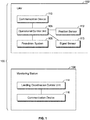
- FIG. 1 is a box diagram of a UAV landing system 100, according to an exemplary embodiment of the present disclosure.
- the UAV landing system 100 includes a UAV 102 and a monitoring station 104.
- the monitoring station 104 may be at or proximate a particular location at which the UAV 102 is to land.
- the monitoring station 104 is configured to communicate with the UAV 102, such as through infrared, laser, ultrasound, radio, and/or other such wireless signals.
- the UAV 102 includes an operational control unit 106 that is operatively coupled to a propulsion system 108, a communication device 110, and a position sensor 112, such as through one or more wired or wireless connections.
- the propulsion system 108 may include one or more turbofan engines, one or more propellers, one or more rotors (such as used with helicopters), and/or the like.
- the communication device 110 may be an antenna, transceiver, radio, camera, and/or the like that is configured to receive and transmit wireless communication signals.
- the position sensor 112 may be a navigational device, such as a global positioning system (GPS) device, that is configured to detect and determine a position of the UAV in relation to a destination, for example.
- GPS global positioning system
- the monitoring station 104 may be a land-based station at or proximate to the destination.
- the monitoring station 104 may be remotely located from the destination.
- the monitoring station 104 may be onboard an aircraft, watercraft, spacecraft, or the like.
- the monitoring station 104 may be onboard a geosynchronous satellite.
- the monitoring station 104 includes a landing coordination control unit 114 operatively coupled to a communication device 116, such as an antenna, transceiver, radio, camera, and/or the like that is configured to receive and transmit wireless communication signals.
- a communication device 116 such as an antenna, transceiver, radio, camera, and/or the like that is configured to receive and transmit wireless communication signals.
- the landing coordination control unit 114 may transmit landing instructions to the UAV 102 through the communication device 116.
- the UAV 102 and the monitoring station 104 communicate with one another through the respective communication devices 110 and 116.
- the landing coordination control unit 114 may be onboard the UAV 102, instead of within the monitoring station 104.
- the UAV 102 departs from a departure location towards a destination according to a normal operating mode, instructions for which may be stored within a memory of the operational control unit 106 (and/or a memory coupled to the operational control unit 106).
- the normal operating mode includes normal instructions for flying and navigating to the destination. For example, in the normal operation mode, the UAV 102 flies and navigates towards the destination according to a flight plan.
- the UAV 102 switches form the normal operating mode to a landing mode.
- the landing mode includes landing instructions for a landing sequence into a landing zone at the destination.
- the landing coordination control unit 114 outputs a landing mode signal to the UAV 102.
- the UAV 102 receives the landing mode signal from the monitoring station 104.
- the operational control unit 106 receives the landing mode signal, and switches the UAV 102 to the landing mode.
- the landing mode signal output from the monitoring station includes instructions for a landing sequence.
- the operational control unit 106 is preprogrammed with the instructions for the landing sequence, and the landing mode signal from the monitoring station simply causes the operational control unit 106 of the UAV 102 to switch from the normal operating mode to the landing mode.
- the landing coordination control unit 114 overtakes operational control of the UAV 102 to automatically land the UAV 102 at the destination.
- the landing sequence provides a coordinated, controlled landing of the UAV 102.
- the landing sequence may cause the UAV 102 to initiate a holding pattern at a particular altitude (such as 100 feet) for a predetermined time (such as 30 seconds), after which the UAV may descend to a lower altitude (such as 50 feet) for a predetermined time (such as 20 seconds), before an approach and landing at a landing zone at the destination.
- the landing sequence may include additional, less, and/or different holding patterns (or no holding patterns) for longer or shorter periods than indicated. It is to be understood that the landing sequence noted is merely a non-limiting example.
- a landing sequence may differ for different UAVs 102 based on UAV traffic in relation to a destination. For example, if numerous UAVs 102 are proximate to the destination, the landing sequence for each UAV 102 may include different holding patterns. As another example, if a relatively low number of UAVs 102 are proximate to the destination, the landing sequence may not include any holding patterns, but may simply include a direct approach and landing procedure.
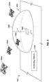
- FIG. 2 is a schematic diagram of the UAV landing system 100 that is configured to coordinate arrival and landing of UAVs 102a, 102b, 102c, and 102d at a landing zone 200 at a destination 202, according to an exemplary embodiment of the present disclosure.
- the UAVs 102a, 102b, 102c, and 102d are proximate to the destination 202, and are to land at the landing zone 200. More or less UAVs than shown may be proximate to the destination 202.
- a regulated airspace 204 is defined at the destination 202 above and around the landing zone 200.
- the regulated airspace 204 may be a hemispherical volume of space.
- the regulated airspace 204 may be defined by a radial distance r from a center of the landing zone 200.
- the radial distance r may be 200 feet, for example. It is to be understood that 200 feet is merely a non-limiting example.
- the radial distance r may optionally be greater or less than 200 feet (such as 1 mile or 50 feet).
- the regulated airspace 204 may be shaped other than a hemisphere.
- the regulated airspace 204 may be cylindrical or conical.
- the UAVs 102a, 102b, 102c, and 102d fly towards the destination 202 according to normal operating modes outside of the regulated airspace 204.
- the UAVs 102a, 102b, 102c, and 102d enter the regulated airspace 204 (such as the UAV 102c shown in Figure 1 )
- the UAVs 102a, 102b, 102c, and 102d switch to the landing modes.
- the monitoring station 104 may output the landing mode signal to the UAVs 102a, 102b, 102c, and 102d upon entry into the regulated airspace 204.
- the landing coordination control unit 114 automatically coordinates the landing of the UAVs 102a, 102b, 102c, and 102d at the landing zone 200, such as based on the order at which the UAVs 102a, 102b, 102c, and 102d enter the regulated airspace 204.
- the position sensors 112 determine the locations of the UAVs 102a, 102b, 102c, and 102d.
- the landing coordination control unit 114 receives the communicated position signals of the UAVs 102a, 102b, 102c, and 102d.
- the monitoring station 104 may track positions of the UAVs 102a, 102b, 102c, and 102d through separate tracking systems, such as radar, satellite tracking, ADS-B, and/or the like.
- the UAV 102c is within the regulated airspace 204. As such, the UAV 102c is the first to switch to the landing mode, and therefore may be the first to land at the landing zone 200. The order of landing is based on the time each of the UAVs 102a, 102b, 102c, and 102d enters the regulated airspace 204.
- the landing coordination control unit 114 may be housed within the monitoring station 104.
- one or more of the UAVs 102a, 102b, 102c, and 102d may include the landing coordination control unit 114.
- an operational control unit 106 of at least one of the UAVs 102a, 102b, 102c, and 102d may include a landing coordination control unit 114 (or, the landing coordination control unit 114 may be operatively coupled to the operational control unit 106).
- each of the UAVs 102a, 102b 102c, and 102d may include a separate landing coordination control unit 114.
- the UAV landing system 100 may not include the separate and distinct monitoring station 104.
- the landing coordination control unit 114 may be onboard at least one UAV 102a, 102b, 102c, and 102d, and the UAVs 102a, 102b, 102c, and 102d may communicate among themselves to coordinate landing of each of the UAVs 102a, 102b, 102c, and 102d.
- the UAVs 102 operate according to a normal operation mode outside of the regulated airspace 204 to fly and navigate towards the destination 202.
- the UAVs 102 switch to the landing mode.
- the UAVs 102 may have instructions for a landing sequence stored within a memory, and/or may receive instructions for the landing sequence from the landing coordination control unit 114.
- the UAVs 102 follow the instructions for the landing sequence to automatically land at the landing zone 200.
- the landing coordination control unit 114 overtakes operational control of the UAVs 102 in the landing mode to automatically land them at the landing zone 200.
- the instructions for the landing sequence may be stored within a memory of the landing coordination control unit 114, and, instead of merely communicating the instructions to the UAV 102, the landing coordination control unit 114 may control the UAVs 102 in the landing mode according to the instructions.
- the landing coordination control unit 114 provides instructions that define one or more procedures for arrival and landing of the UAVs 102.
- the instructions are automatically output and/or otherwise followed in response to the UAVs 102 entering the regulated airspace 204 (such as upon the UAVs 102 reaching a predetermined distance to the landing zone 200).
- Each procedure assigned to a UAV 102 may be adapted for the performance of a particular UAV 102 (such as current speed, distance, angular position, and/or the like).
- the UAV 102 may include a signal sensor 113 (such as an ultrasound, infrared, laser, or other such sensor), which may be configured to detect corresponding signals output by the monitoring station 104.
- a signal sensor 113 such as an ultrasound, infrared, laser, or other such sensor
- the UAV 102 switches to the landing mode, and activates the signal sensor 113 to scan for and detect signals output by the monitoring station 104.
- the UAV 102 may be in a holding pattern.
- the signal(s) output by the monitoring station 104 may include the instructions for a landing sequence.
- the UAV 102 may then initiate a landing sequence based on the received instructions.
- the UAV 102 may not include the signal sensor 113, but instead may be in communication with the landing coordination control unit 114 as described herein.
- control unit central processing unit
- unit unit
- CPU central processing unit
- ASIC application specific integrated circuits
- the operational control unit 106 and the landing coordination control unit 114 may be or include one or more processors that are configured to control operation of the UAV 102s, as described herein.
- the operational control unit 106 and the landing coordination control unit 114 are configured to execute a set of instructions that are stored in one or more data storage units or elements (such as one or more memories), in order to process data.
- the operational control unit 106 and the landing coordination control unit 114 may include or be coupled to one or more memories.
- the data storage units may also store data or other information as desired or needed.
- the data storage units may be in the form of an information source or a physical memory element within a processing machine.
- the set of instructions may include various commands that instruct the operational control unit 106 and the landing coordination control unit 114 as processing machines to perform specific operations such as the methods and processes of the various embodiments of the subject matter described herein.
- the set of instructions may be in the form of a software program.
- the software may be in various forms such as system software or application software. Further, the software may be in the form of a collection of separate programs, a program subset within a larger program or a portion of a program.
- the software may also include modular programming in the form of object-oriented programming.
- the processing of input data by the processing machine may be in response to user commands, or in response to results of previous processing, or in response to a request made by another processing machine.
- the diagrams of embodiments herein may illustrate one or more control or processing units, such as the operational control unit 106 and the landing coordination control unit 114.
- the processing or control units may represent circuits, circuitry, or portions thereof that may be implemented as hardware with associated instructions (e.g., software stored on a tangible and non-transitory computer readable storage medium, such as a computer hard drive, ROM, RAM, or the like) that perform the operations described herein.
- the hardware may include state machine circuitry hardwired to perform the functions described herein.
- the hardware may include electronic circuits that include and/or are connected to one or more logic-based devices, such as microprocessors, processors, controllers, or the like.
- the operational control unit 106 and the landing coordination control unit 114 may represent processing circuitry such as one or more of a field programmable gate array (FPGA), application specific integrated circuit (ASIC), microprocessor(s), and/or the like.
- the circuits in various embodiments may be configured to execute one or more algorithms to perform functions described herein.
- the one or more algorithms may include aspects of embodiments disclosed herein, whether or not expressly identified in a flowchart or a method.
- the terms "software” and “firmware” are interchangeable, and include any computer program stored in a data storage unit (for example, one or more memories) for execution by a computer, including RAM memory, ROM memory, EPROM memory, EEPROM memory, and non-volatile RAM (NVRAM) memory.
- a data storage unit for example, one or more memories
- NVRAM non-volatile RAM
- the above data storage unit types are exemplary only, and are thus not limiting as to the types of memory usable for storage of a computer program.
- FIG. 3 is a diagrammatic representation of a top view of a UAV 102, according to an exemplary embodiment of the present disclosure.
- the UAV 102 may include an airframe 320 and a plurality of propulsion systems 322 coupled to the airframe 320.
- the airframe 320 forms the structural body or framework for the UAV 102.
- the UAV 102 includes four propulsion systems 322, such that each propulsion system 322 is mounted to a respective arm 324, 325, 326, and 327.
- the UAV 102 includes four arms 324-327 and a single propulsion system 322 that is mounted to each respective arm 324-327.
- the UAV 102 may include more or less propulsion systems 322, more or less propulsion systems 322 per arm 324-327, and more or less arms 324-327 than shown.
- the UAV 102 shown in Figure 3 is merely one example of a UAV 102.
- the UAV 102 may optionally be a fixed wing plane with various other types of propulsion systems.
- the UAV 102 may be an unmanned plane having one or more propellers, jet engines, and/or the like.
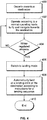
- FIG 4 illustrates a flow chart of a UAV landing method, according to an exemplary embodiment of the present disclosure.
- the method begins at 400, at which a UAV 102 departs from a starting location towards the destination 202.
- the UAV 102 operates according to the normal operating mode to fly and navigate towards the destination 202.
- the landing coordination control unit 114 determines whether the UAV 102 is within the regulated airspace 204 over and around the landing zone 200 at the destination 202. If the UAV 102 is not within the regulated airspace 204, the method returns to 402.
- the method proceeds from 404 to 406, at which the UAV 102 switches to the landing mode.
- the UAV 102 may receive instructions for a landing sequence from the landing coordination control unit 114.
- the landing coordination control unit 114 of the monitoring station 104 may transmit the landing instructions to the UAV 102.
- the UAV 102 then automatically lands (without human intervention) at the landing zone 200 at the destination 202 according to the instruction for the landing sequence.
- the method then ends at 410.
- embodiments of the present disclosure provide UAV landing systems and methods that do not require human intervention.
- the UAV landing systems and methods automatically, efficiently, and safely coordinate arrivals of UAVs at a particular destination.
- Embodiments of the present disclosure provide systems and methods that allow large amounts of data to be quickly and efficiently analyzed by a computing device. For example, hundreds if not thousands of UAVs may attempt to land at a destination during the course of a day. The number of UAVs may exceed the number of commercial aircraft within an airspace during that time. The vast amounts of data are efficiently analyzed by the landing coordination control unit 114, as described herein.
- the UAV landing systems and methods analyze data regarding the UAVs in a relatively short time.
- a human being such as an air traffic controller already preoccupied with commercial aircraft
- embodiments of the present disclosure provide superior performance in relation to a human being analyzing the vast amounts of data.
- embodiments of the present disclosure provide systems and methods that analyze thousands, if not millions, of calculations and computations that a human being is incapable of efficiently, effectively and accurately managing.
- a structure, limitation, or element that is "configured to” perform a task or operation is particularly structurally formed, constructed, or adapted in a manner corresponding to the task or operation.
- an object that is merely capable of being modified to perform the task or operation is not “configured to” perform the task or operation as used herein.
Landscapes
- Engineering & Computer Science (AREA)
- Aviation & Aerospace Engineering (AREA)
- Physics & Mathematics (AREA)
- General Physics & Mathematics (AREA)
- Radar, Positioning & Navigation (AREA)
- Remote Sensing (AREA)
- Automation & Control Theory (AREA)
- Traffic Control Systems (AREA)
Claims (15)
- System (100) zum Landen einer Vielzahl von unbemannten Luftfahrzeugen, UAVs, (102a, 102b, 102c, 102d) an einem Ziel (202), wobei das System aufweist:eine Landekoordination-Steuereinheit (114), die konfiguriert ist, ein Landemodussignal an die UAVs auszugeben, um als Antwort auf einen Eintritt der UAVs (102a, 102b, 102c, 102d) in einen regulierten Luftraum (204) in Bezug auf das Ziel (202) die UAVs von einem normalen Betriebsmodus in einen Landemodus umzustellen, wobei der normale Betriebsmodus normale Befehle zum Fliegen und Navigieren zu dem Ziel (202) aufweist, und wobei der Landemodus Landebefehle für eine automatische Landesequenz in eine Landezone (200) an dem Ziel (202) aufweist,wobei die Landekoordination-Steuereinheit (114) konfiguriert ist, abhängig von einer Zeit, an der jedes der UAVs (102a, 102b, 102c, 102d) in den regulierten Luftraum (204) eintritt, eine Reihenfolge zu bestimmen, in der die UAVs an dem Ziel (202) landen.
- System (100) nach Anspruch 1, ferner aufweisend eine Überwachungsstation (104), die separat und verschieden von den UAVs (102a, 102b, 102c, 102d) ist, wobei die Überwachungsstation (104) die Landekoordination-Steuereinheit (114) aufweist.
- System (100) nach Anspruch 2, wobei die Überwachungsstation (104) an dem Ziel (202) angeordnet ist.
- System (100) nach Anspruch 1, ferner aufweisend eines oder mehrere der UAVs (102a, 102b, 102c, 102d), wobei das eine oder die mehreren der UAVs die Landekoordination-Steuereinheit (114) aufweist/aufweisen.
- System (100) nach einem der Ansprüche 1 bis 4, wobei die Landekoordination-Steuereinheit (114) konfiguriert ist, eine Steuerung des Betriebs der UAVs in dem Landemodus zu übernehmen, um die UAVs automatisch an der Landezone (200) zu landen.
- System (100) nach einem der Ansprüche 1 bis 5, wobei die Landekoordination-Steuereinheit (104) konfiguriert ist, die Landebefehle zu den UAVs zu senden.
- System (100) nach einem der Ansprüche 1 bis 6, ferner aufweisend die UAVs, und wobei die Landebefehle in einer Betriebssteuereinheit (106) der UAVs gespeichert sind.
- System (100) nach einem der Ansprüche 1 bis 7, ferner aufweisend die UAVs, und wobei die UAVs einen Signalsensor (113) aufweisen, der konfiguriert ist, ein Signal aus der Landekoordination-Steuereinheit (114) zu detektieren.
- Verfahren zum Landen einer Vielzahl von unbemannten Luftfahrzeugen, UAVs, (102a, 102b, 102c, 102d) an einem Ziel (202), wobei das Verfahren aufweist:Verwenden einer Landekoordination-Steuereinheit (114), um ein Landemodussignal an die UAVs auszuzugeben, um als Antwort auf einen Eintritt der UAVs in einen regulierten Luftraum (204) in Bezug auf das Ziel (202) die UAVs von einem normalen Betriebsmodus in einen Landemodus umzustellen, wobei der normale Betriebsmodus normale Befehle zum Fliegen und Navigieren zu dem Ziel (202) aufweist, und wobei der Landemodus Landebefehle für eine automatische Landesequenz in eine Landezone (200) an dem Ziel (202) aufweist,wobei eine Reihenfolge, in der die UAVs an dem Ziel (202) landen, abhängig von einer Zeit ist, an der jedes der UAVs in den regulierten Luftraum (204) eintritt.
- Verfahren nach Anspruch 9, ferner aufweisend Anordnen der Landekoordination-Steuereinheit (114) in einer Überwachungsstation (104), die separat und verschieden von den UAVs ist.
- Verfahren nach Anspruch 9, ferner aufweisend Anordnen der Landekoordination-Steuereinheit (114) in einem oder mehreren der UAVs.
- Verfahren nach einem der Ansprüche 9 bis 11, wobei das Verwenden der Landekoordination-Steuereinheit (114) aufweist: Übernehmen der Steuerung des Betriebs des UAV (102) in dem Landemodus, um die UAVs automatisch an der Landezone (200) zu landen.
- Verfahren nach einem der Ansprüche 9 bis 12, wobei das Verwenden der Landekoordination-Steuereinheit (114) aufweist: Senden der Landebefehle zu den UAVs.
- Verfahren nach einem der Ansprüche 9 bis 13, ferner aufweisend Speichern der Landebefehle in einer Betriebssteuereinheit (106) der UAVs.
- Verfahren nach einem der Ansprüche 9 bis 14, ferner aufweisend Detektieren eines Signals aus der Landekoordination-Steuereinheit (114) mit Hilfe eines Signalsensors (113) der UAVs.
Applications Claiming Priority (1)
| Application Number | Priority Date | Filing Date | Title |
|---|---|---|---|
| US15/806,987 US10429838B2 (en) | 2017-11-08 | 2017-11-08 | Unmanned aerial vehicle (UAV) landing systems and methods |
Publications (2)
| Publication Number | Publication Date |
|---|---|
| EP3483066A1 EP3483066A1 (de) | 2019-05-15 |
| EP3483066B1 true EP3483066B1 (de) | 2021-04-07 |
Family
ID=63878596
Family Applications (1)
| Application Number | Title | Priority Date | Filing Date |
|---|---|---|---|
| EP18201103.1A Active EP3483066B1 (de) | 2017-11-08 | 2018-10-18 | Landesysteme und verfahren für unbemanntes luftfahrzeug |
Country Status (4)
| Country | Link |
|---|---|
| US (2) | US10429838B2 (de) |
| EP (1) | EP3483066B1 (de) |
| JP (2) | JP7679165B2 (de) |
| CN (1) | CN109747847B (de) |
Families Citing this family (12)
| Publication number | Priority date | Publication date | Assignee | Title |
|---|---|---|---|---|
| US11682312B2 (en) * | 2018-07-20 | 2023-06-20 | Atc Technologies, Llc | Devices, systems, and methods for autonomously landing unmanned aerial vehicles with collaborative information sharing |
| US11170653B2 (en) * | 2018-08-01 | 2021-11-09 | Potomac Aviation Technology Corp. | Automated air-traffic advisory system and method |
| US11928976B2 (en) * | 2019-03-27 | 2024-03-12 | Reliable Robotics Corporation | Cross-checking localization during aircraft terminal operations |
| US11235875B2 (en) * | 2019-05-08 | 2022-02-01 | Ford Global Technologies, Llc | Zone-based unmanned aerial vehicle landing systems and methods |
| US11479370B2 (en) * | 2019-05-28 | 2022-10-25 | The Boeing Company | Aircraft turnaround monitoring systems and methods |
| CN110941282A (zh) * | 2019-11-15 | 2020-03-31 | 西北工业大学 | 一种用于无人机着陆的控制方法、系统、设备及可读存储介质 |
| RU2733453C1 (ru) * | 2020-07-07 | 2020-10-01 | федеральное государственное автономное образовательное учреждение высшего образования "Северо-Кавказский федеральный университет" | Способ автоматического управления движением роботизированного беспилотного летательного аппарата в автономном режиме |
| CN114167884B (zh) * | 2020-09-11 | 2025-02-07 | 丰翼科技(深圳)有限公司 | 无人机控制方法、装置、计算机设备及存储介质 |
| AU2021204693A1 (en) * | 2020-09-23 | 2022-04-07 | Insitu, Inc. (A Subsidiary Of The Boeing Company) | A controlled powerup sequence for an unmanned aerial vehicle (UAV) |
| US12103705B2 (en) | 2022-11-09 | 2024-10-01 | Lucas Trenshaw | Aerial drone with rotating frame |
| WO2025191596A1 (en) * | 2024-03-12 | 2025-09-18 | Tvs Motor Company Limited | A system and method for assisting landing of an unmanned aerial vehicle |
| WO2025215039A1 (en) * | 2024-04-08 | 2025-10-16 | Birdview As | A system and method for takeoff and landing of an unmanned aerial vehicle (uav) |
Family Cites Families (27)
| Publication number | Priority date | Publication date | Assignee | Title |
|---|---|---|---|---|
| WO2003003041A2 (en) | 2001-06-29 | 2003-01-09 | Honeywell International Inc. | 3-d weather buffer display system |
| GB0307138D0 (en) | 2003-03-27 | 2003-04-30 | British Telecomm | Sequencing vehicles |
| US7343232B2 (en) * | 2003-06-20 | 2008-03-11 | Geneva Aerospace | Vehicle control system including related methods and components |
| US20060155432A1 (en) | 2005-01-07 | 2006-07-13 | United Technologies Corporation | Methods and systems for monitoring atmospheric conditions, predicting turbulent atmospheric conditions and optimizing flight paths of aircraft |
| US8838289B2 (en) | 2006-04-19 | 2014-09-16 | Jed Margolin | System and method for safely flying unmanned aerial vehicles in civilian airspace |
| US8135503B2 (en) | 2010-04-27 | 2012-03-13 | Honeywell International Inc. | Ground proximity sensor |
| JP5171881B2 (ja) * | 2010-05-14 | 2013-03-27 | 中国電力株式会社 | 無人飛行体の着陸を支援する方法、及び無人飛行体 |
| US8314730B1 (en) | 2010-12-14 | 2012-11-20 | The Boeing Company | Collection of meteorological data by vehicles |
| US9208457B2 (en) | 2012-09-20 | 2015-12-08 | The Boeing Company | Optimized flight plan management system |
| US20150379408A1 (en) | 2014-06-30 | 2015-12-31 | Microsoft Corporation | Using Sensor Information for Inferring and Forecasting Large-Scale Phenomena |
| US9845165B2 (en) * | 2014-07-16 | 2017-12-19 | Airogistic, L.L.C. | Methods and apparatus for unmanned aerial vehicle landing and launch |
| CN106068592B (zh) * | 2014-08-08 | 2021-06-11 | 深圳市大疆创新科技有限公司 | 无人飞行器电池更换系统及方法 |
| US9359074B2 (en) * | 2014-09-08 | 2016-06-07 | Qualcomm Incorporated | Methods, systems and devices for delivery drone security |
| US9387928B1 (en) | 2014-12-18 | 2016-07-12 | Amazon Technologies, Inc. | Multi-use UAV docking station systems and methods |
| US9540121B2 (en) * | 2015-02-25 | 2017-01-10 | Cisco Technology, Inc. | Pre-flight self test for unmanned aerial vehicles (UAVs) |
| JP6463185B2 (ja) * | 2015-03-26 | 2019-01-30 | 株式会社Subaru | 飛行経路作成装置、飛行経路作成方法及び飛行経路作成プログラム |
| US9701408B1 (en) | 2015-06-15 | 2017-07-11 | Amazon Technologies, Inc. | Determining landing locations |
| CN107848618B (zh) * | 2015-07-06 | 2021-11-02 | 株式会社0 | 旋翼机着陆装置 |
| US9889932B2 (en) | 2015-07-18 | 2018-02-13 | Tata Consultancy Services Limited | Methods and systems for landing of unmanned aerial vehicle |
| JP6203789B2 (ja) * | 2015-08-06 | 2017-09-27 | Simplex Quantum株式会社 | 小型飛行システム |
| US10061328B2 (en) * | 2015-08-12 | 2018-08-28 | Qualcomm Incorporated | Autonomous landing and control |
| US10167092B2 (en) | 2015-08-19 | 2019-01-01 | Cisco Technology, Inc. | Perch for screening drones |
| US20180290731A1 (en) | 2015-12-25 | 2018-10-11 | Sharp Kabushiki Kaisha | Mobile body, communication terminal, and control method for mobile body |
| US20170212528A1 (en) * | 2016-01-26 | 2017-07-27 | Patrick A. Henderson | Apparatus and Method for Autonomous Landing of an Aerial Vehicle |
| US20170283054A1 (en) * | 2016-03-29 | 2017-10-05 | Chengwen Chris WANG | Unmanned spatial vehicle performance |
| KR101777273B1 (ko) * | 2016-03-31 | 2017-09-12 | 주식회사 엑센스 | 드론의 정밀한 착륙을 위한 도킹 장치 |
| EP3932087B1 (de) | 2019-02-27 | 2024-06-26 | Dolby Laboratories Licensing Corporation | Akustischer reflektor für höhenkanal-lautsprecher |
-
2017
- 2017-11-08 US US15/806,987 patent/US10429838B2/en active Active
-
2018
- 2018-10-18 EP EP18201103.1A patent/EP3483066B1/de active Active
- 2018-10-19 JP JP2018197469A patent/JP7679165B2/ja active Active
- 2018-11-07 CN CN201811319906.4A patent/CN109747847B/zh active Active
-
2019
- 2019-08-21 US US16/546,350 patent/US11137756B2/en active Active
-
2024
- 2024-01-11 JP JP2024002597A patent/JP7741213B2/ja active Active
Non-Patent Citations (1)
| Title |
|---|
| None * |
Also Published As
| Publication number | Publication date |
|---|---|
| US20190137997A1 (en) | 2019-05-09 |
| US10429838B2 (en) | 2019-10-01 |
| EP3483066A1 (de) | 2019-05-15 |
| JP2024032770A (ja) | 2024-03-12 |
| JP2019087238A (ja) | 2019-06-06 |
| JP7741213B2 (ja) | 2025-09-17 |
| JP7679165B2 (ja) | 2025-05-19 |
| US11137756B2 (en) | 2021-10-05 |
| US20190377337A1 (en) | 2019-12-12 |
| CN109747847B (zh) | 2025-03-25 |
| CN109747847A (zh) | 2019-05-14 |
Similar Documents
| Publication | Publication Date | Title |
|---|---|---|
| EP3483066B1 (de) | Landesysteme und verfahren für unbemanntes luftfahrzeug | |
| EP3717352B1 (de) | Autonomes unbemanntes luftfahrzeug und steuerungsverfahren dafür | |
| US11037453B2 (en) | Adaptive sense and avoid system | |
| US10013885B2 (en) | Airspace deconfliction system and method | |
| EP3866138A1 (de) | Systeme und verfahren zur automatischen fahrzeugübergreifenden navigation unter verwendung von sensordatenfusion | |
| CN110738872A (zh) | 用于空中交通工具的飞行控制系统和相关方法 | |
| EP3618038B1 (de) | Systeme und verfahren zur überwachung eines eingeschränkten luftraums und verfahren | |
| US20230028792A1 (en) | Machine learning architectures for camera-based detection and avoidance on aircrafts | |
| CN105404291A (zh) | 用于无人飞行器运载工具的跟随系统 | |
| EP3816970B1 (de) | Systeme und verfahren zur verteilten avionikverarbeitung | |
| WO2017125916A1 (en) | Method and system for emulating modular agnostic control of commercial unmanned aerial vehicles (uavs) | |
| EP4063987A1 (de) | Systeme und verfahren zur identifizierung von landezonen für unbemannte flugzeuge | |
| JP2023029358A (ja) | 自動管制システム、自動管制方法、及び自動管制装置 | |
| JP2004175209A (ja) | 無人航空機 | |
| Di Vito et al. | A tactical separation system for small air transport vehicles | |
| Di Vito et al. | Conceptual design of a pilot’s decision-making support system for tactical separation of small air transport vehicles in future SESAR ATM environment | |
| Bhandari et al. | UAV collision detection and avoidance using ADS-B sensor and custom ADS-B like solution | |
| EP4478334A1 (de) | Taktische entkonferenz von unbemannten luftfahrzeugen | |
| KR101842217B1 (ko) | 비행 제어 장치, 그 방법 및 이를 포함하는 비행 제어 시스템 | |
| WO2025088470A1 (en) | Aircraft systems | |
| JP2026055204A (ja) | 情報制御システム、情報制御方法またはプログラム |
Legal Events
| Date | Code | Title | Description |
|---|---|---|---|
| PUAI | Public reference made under article 153(3) epc to a published international application that has entered the european phase |
Free format text: ORIGINAL CODE: 0009012 |
|
| STAA | Information on the status of an ep patent application or granted ep patent |
Free format text: STATUS: REQUEST FOR EXAMINATION WAS MADE |
|
| 17P | Request for examination filed |
Effective date: 20181018 |
|
| AK | Designated contracting states |
Kind code of ref document: A1 Designated state(s): AL AT BE BG CH CY CZ DE DK EE ES FI FR GB GR HR HU IE IS IT LI LT LU LV MC MK MT NL NO PL PT RO RS SE SI SK SM TR |
|
| AX | Request for extension of the european patent |
Extension state: BA ME |
|
| RBV | Designated contracting states (corrected) |
Designated state(s): AL AT BE BG CH CY CZ DE DK EE ES FI FR GB GR HR HU IE IS IT LI LT LU LV MC MK MT NL NO PL PT RO RS SE SI SK SM TR |
|
| GRAP | Despatch of communication of intention to grant a patent |
Free format text: ORIGINAL CODE: EPIDOSNIGR1 |
|
| STAA | Information on the status of an ep patent application or granted ep patent |
Free format text: STATUS: GRANT OF PATENT IS INTENDED |
|
| INTG | Intention to grant announced |
Effective date: 20200715 |
|
| GRAJ | Information related to disapproval of communication of intention to grant by the applicant or resumption of examination proceedings by the epo deleted |
Free format text: ORIGINAL CODE: EPIDOSDIGR1 |
|
| STAA | Information on the status of an ep patent application or granted ep patent |
Free format text: STATUS: REQUEST FOR EXAMINATION WAS MADE |
|
| GRAP | Despatch of communication of intention to grant a patent |
Free format text: ORIGINAL CODE: EPIDOSNIGR1 |
|
| STAA | Information on the status of an ep patent application or granted ep patent |
Free format text: STATUS: GRANT OF PATENT IS INTENDED |
|
| INTC | Intention to grant announced (deleted) | ||
| INTG | Intention to grant announced |
Effective date: 20201026 |
|
| GRAS | Grant fee paid |
Free format text: ORIGINAL CODE: EPIDOSNIGR3 |
|
| GRAA | (expected) grant |
Free format text: ORIGINAL CODE: 0009210 |
|
| STAA | Information on the status of an ep patent application or granted ep patent |
Free format text: STATUS: THE PATENT HAS BEEN GRANTED |
|
| AK | Designated contracting states |
Kind code of ref document: B1 Designated state(s): AL AT BE BG CH CY CZ DE DK EE ES FI FR GB GR HR HU IE IS IT LI LT LU LV MC MK MT NL NO PL PT RO RS SE SI SK SM TR |
|
| REG | Reference to a national code |
Ref country code: GB Ref legal event code: FG4D |
|
| REG | Reference to a national code |
Ref country code: AT Ref legal event code: REF Ref document number: 1379382 Country of ref document: AT Kind code of ref document: T Effective date: 20210415 Ref country code: CH Ref legal event code: EP |
|
| REG | Reference to a national code |
Ref country code: DE Ref legal event code: R096 Ref document number: 602018015075 Country of ref document: DE |
|
| REG | Reference to a national code |
Ref country code: IE Ref legal event code: FG4D |
|
| REG | Reference to a national code |
Ref country code: LT Ref legal event code: MG9D |
|
| REG | Reference to a national code |
Ref country code: NL Ref legal event code: MP Effective date: 20210407 Ref country code: AT Ref legal event code: MK05 Ref document number: 1379382 Country of ref document: AT Kind code of ref document: T Effective date: 20210407 |
|
| PG25 | Lapsed in a contracting state [announced via postgrant information from national office to epo] |
Ref country code: NL Free format text: LAPSE BECAUSE OF FAILURE TO SUBMIT A TRANSLATION OF THE DESCRIPTION OR TO PAY THE FEE WITHIN THE PRESCRIBED TIME-LIMIT Effective date: 20210407 Ref country code: AT Free format text: LAPSE BECAUSE OF FAILURE TO SUBMIT A TRANSLATION OF THE DESCRIPTION OR TO PAY THE FEE WITHIN THE PRESCRIBED TIME-LIMIT Effective date: 20210407 Ref country code: BG Free format text: LAPSE BECAUSE OF FAILURE TO SUBMIT A TRANSLATION OF THE DESCRIPTION OR TO PAY THE FEE WITHIN THE PRESCRIBED TIME-LIMIT Effective date: 20210707 Ref country code: FI Free format text: LAPSE BECAUSE OF FAILURE TO SUBMIT A TRANSLATION OF THE DESCRIPTION OR TO PAY THE FEE WITHIN THE PRESCRIBED TIME-LIMIT Effective date: 20210407 Ref country code: LT Free format text: LAPSE BECAUSE OF FAILURE TO SUBMIT A TRANSLATION OF THE DESCRIPTION OR TO PAY THE FEE WITHIN THE PRESCRIBED TIME-LIMIT Effective date: 20210407 Ref country code: HR Free format text: LAPSE BECAUSE OF FAILURE TO SUBMIT A TRANSLATION OF THE DESCRIPTION OR TO PAY THE FEE WITHIN THE PRESCRIBED TIME-LIMIT Effective date: 20210407 |
|
| PG25 | Lapsed in a contracting state [announced via postgrant information from national office to epo] |
Ref country code: RS Free format text: LAPSE BECAUSE OF FAILURE TO SUBMIT A TRANSLATION OF THE DESCRIPTION OR TO PAY THE FEE WITHIN THE PRESCRIBED TIME-LIMIT Effective date: 20210407 Ref country code: SE Free format text: LAPSE BECAUSE OF FAILURE TO SUBMIT A TRANSLATION OF THE DESCRIPTION OR TO PAY THE FEE WITHIN THE PRESCRIBED TIME-LIMIT Effective date: 20210407 Ref country code: LV Free format text: LAPSE BECAUSE OF FAILURE TO SUBMIT A TRANSLATION OF THE DESCRIPTION OR TO PAY THE FEE WITHIN THE PRESCRIBED TIME-LIMIT Effective date: 20210407 Ref country code: NO Free format text: LAPSE BECAUSE OF FAILURE TO SUBMIT A TRANSLATION OF THE DESCRIPTION OR TO PAY THE FEE WITHIN THE PRESCRIBED TIME-LIMIT Effective date: 20210707 Ref country code: PL Free format text: LAPSE BECAUSE OF FAILURE TO SUBMIT A TRANSLATION OF THE DESCRIPTION OR TO PAY THE FEE WITHIN THE PRESCRIBED TIME-LIMIT Effective date: 20210407 Ref country code: PT Free format text: LAPSE BECAUSE OF FAILURE TO SUBMIT A TRANSLATION OF THE DESCRIPTION OR TO PAY THE FEE WITHIN THE PRESCRIBED TIME-LIMIT Effective date: 20210809 Ref country code: IS Free format text: LAPSE BECAUSE OF FAILURE TO SUBMIT A TRANSLATION OF THE DESCRIPTION OR TO PAY THE FEE WITHIN THE PRESCRIBED TIME-LIMIT Effective date: 20210807 Ref country code: GR Free format text: LAPSE BECAUSE OF FAILURE TO SUBMIT A TRANSLATION OF THE DESCRIPTION OR TO PAY THE FEE WITHIN THE PRESCRIBED TIME-LIMIT Effective date: 20210708 |
|
| REG | Reference to a national code |
Ref country code: DE Ref legal event code: R097 Ref document number: 602018015075 Country of ref document: DE |
|
| PG25 | Lapsed in a contracting state [announced via postgrant information from national office to epo] |
Ref country code: EE Free format text: LAPSE BECAUSE OF FAILURE TO SUBMIT A TRANSLATION OF THE DESCRIPTION OR TO PAY THE FEE WITHIN THE PRESCRIBED TIME-LIMIT Effective date: 20210407 Ref country code: ES Free format text: LAPSE BECAUSE OF FAILURE TO SUBMIT A TRANSLATION OF THE DESCRIPTION OR TO PAY THE FEE WITHIN THE PRESCRIBED TIME-LIMIT Effective date: 20210407 Ref country code: SM Free format text: LAPSE BECAUSE OF FAILURE TO SUBMIT A TRANSLATION OF THE DESCRIPTION OR TO PAY THE FEE WITHIN THE PRESCRIBED TIME-LIMIT Effective date: 20210407 Ref country code: SK Free format text: LAPSE BECAUSE OF FAILURE TO SUBMIT A TRANSLATION OF THE DESCRIPTION OR TO PAY THE FEE WITHIN THE PRESCRIBED TIME-LIMIT Effective date: 20210407 Ref country code: CZ Free format text: LAPSE BECAUSE OF FAILURE TO SUBMIT A TRANSLATION OF THE DESCRIPTION OR TO PAY THE FEE WITHIN THE PRESCRIBED TIME-LIMIT Effective date: 20210407 Ref country code: DK Free format text: LAPSE BECAUSE OF FAILURE TO SUBMIT A TRANSLATION OF THE DESCRIPTION OR TO PAY THE FEE WITHIN THE PRESCRIBED TIME-LIMIT Effective date: 20210407 Ref country code: RO Free format text: LAPSE BECAUSE OF FAILURE TO SUBMIT A TRANSLATION OF THE DESCRIPTION OR TO PAY THE FEE WITHIN THE PRESCRIBED TIME-LIMIT Effective date: 20210407 |
|
| PLBE | No opposition filed within time limit |
Free format text: ORIGINAL CODE: 0009261 |
|
| STAA | Information on the status of an ep patent application or granted ep patent |
Free format text: STATUS: NO OPPOSITION FILED WITHIN TIME LIMIT |
|
| 26N | No opposition filed |
Effective date: 20220110 |
|
| REG | Reference to a national code |
Ref country code: CH Ref legal event code: PL |
|
| PG25 | Lapsed in a contracting state [announced via postgrant information from national office to epo] |
Ref country code: IS Free format text: LAPSE BECAUSE OF FAILURE TO SUBMIT A TRANSLATION OF THE DESCRIPTION OR TO PAY THE FEE WITHIN THE PRESCRIBED TIME-LIMIT Effective date: 20210807 Ref country code: AL Free format text: LAPSE BECAUSE OF FAILURE TO SUBMIT A TRANSLATION OF THE DESCRIPTION OR TO PAY THE FEE WITHIN THE PRESCRIBED TIME-LIMIT Effective date: 20210407 |
|
| REG | Reference to a national code |
Ref country code: BE Ref legal event code: MM Effective date: 20211031 |
|
| PG25 | Lapsed in a contracting state [announced via postgrant information from national office to epo] |
Ref country code: MC Free format text: LAPSE BECAUSE OF FAILURE TO SUBMIT A TRANSLATION OF THE DESCRIPTION OR TO PAY THE FEE WITHIN THE PRESCRIBED TIME-LIMIT Effective date: 20210407 |
|
| PG25 | Lapsed in a contracting state [announced via postgrant information from national office to epo] |
Ref country code: LU Free format text: LAPSE BECAUSE OF NON-PAYMENT OF DUE FEES Effective date: 20211018 Ref country code: IT Free format text: LAPSE BECAUSE OF FAILURE TO SUBMIT A TRANSLATION OF THE DESCRIPTION OR TO PAY THE FEE WITHIN THE PRESCRIBED TIME-LIMIT Effective date: 20210407 Ref country code: BE Free format text: LAPSE BECAUSE OF NON-PAYMENT OF DUE FEES Effective date: 20211031 |
|
| PG25 | Lapsed in a contracting state [announced via postgrant information from national office to epo] |
Ref country code: LI Free format text: LAPSE BECAUSE OF NON-PAYMENT OF DUE FEES Effective date: 20211031 Ref country code: CH Free format text: LAPSE BECAUSE OF NON-PAYMENT OF DUE FEES Effective date: 20211031 |
|
| PG25 | Lapsed in a contracting state [announced via postgrant information from national office to epo] |
Ref country code: IE Free format text: LAPSE BECAUSE OF NON-PAYMENT OF DUE FEES Effective date: 20211018 |
|
| P01 | Opt-out of the competence of the unified patent court (upc) registered |
Effective date: 20230516 |
|
| PG25 | Lapsed in a contracting state [announced via postgrant information from national office to epo] |
Ref country code: CY Free format text: LAPSE BECAUSE OF FAILURE TO SUBMIT A TRANSLATION OF THE DESCRIPTION OR TO PAY THE FEE WITHIN THE PRESCRIBED TIME-LIMIT Effective date: 20210407 |
|
| PG25 | Lapsed in a contracting state [announced via postgrant information from national office to epo] |
Ref country code: HU Free format text: LAPSE BECAUSE OF FAILURE TO SUBMIT A TRANSLATION OF THE DESCRIPTION OR TO PAY THE FEE WITHIN THE PRESCRIBED TIME-LIMIT; INVALID AB INITIO Effective date: 20181018 |
|
| PG25 | Lapsed in a contracting state [announced via postgrant information from national office to epo] |
Ref country code: MK Free format text: LAPSE BECAUSE OF FAILURE TO SUBMIT A TRANSLATION OF THE DESCRIPTION OR TO PAY THE FEE WITHIN THE PRESCRIBED TIME-LIMIT Effective date: 20210407 |
|
| PG25 | Lapsed in a contracting state [announced via postgrant information from national office to epo] |
Ref country code: MT Free format text: LAPSE BECAUSE OF FAILURE TO SUBMIT A TRANSLATION OF THE DESCRIPTION OR TO PAY THE FEE WITHIN THE PRESCRIBED TIME-LIMIT Effective date: 20210407 |
|
| PG25 | Lapsed in a contracting state [announced via postgrant information from national office to epo] |
Ref country code: TR Free format text: LAPSE BECAUSE OF FAILURE TO SUBMIT A TRANSLATION OF THE DESCRIPTION OR TO PAY THE FEE WITHIN THE PRESCRIBED TIME-LIMIT Effective date: 20210407 |
|
| PGFP | Annual fee paid to national office [announced via postgrant information from national office to epo] |
Ref country code: DE Payment date: 20251029 Year of fee payment: 8 |
|
| PGFP | Annual fee paid to national office [announced via postgrant information from national office to epo] |
Ref country code: GB Payment date: 20251027 Year of fee payment: 8 |
|
| PGFP | Annual fee paid to national office [announced via postgrant information from national office to epo] |
Ref country code: FR Payment date: 20251027 Year of fee payment: 8 |