EP3482970A1 - Druckregelvorrichtung für ein schreibgerät und schreibgerät mit solch einer vorrichtung - Google Patents
Druckregelvorrichtung für ein schreibgerät und schreibgerät mit solch einer vorrichtung Download PDFInfo
- Publication number
- EP3482970A1 EP3482970A1 EP18170575.7A EP18170575A EP3482970A1 EP 3482970 A1 EP3482970 A1 EP 3482970A1 EP 18170575 A EP18170575 A EP 18170575A EP 3482970 A1 EP3482970 A1 EP 3482970A1
- Authority
- EP
- European Patent Office
- Prior art keywords
- deformable member
- external communication
- regulating device
- writing tool
- pressure regulating
- Prior art date
- Legal status (The legal status is an assumption and is not a legal conclusion. Google has not performed a legal analysis and makes no representation as to the accuracy of the status listed.)
- Withdrawn
Links
Images






Classifications
-
- B—PERFORMING OPERATIONS; TRANSPORTING
- B43—WRITING OR DRAWING IMPLEMENTS; BUREAU ACCESSORIES
- B43K—IMPLEMENTS FOR WRITING OR DRAWING
- B43K5/00—Pens with ink reservoirs in holders, e.g. fountain-pens
- B43K5/02—Ink reservoirs
-
- B—PERFORMING OPERATIONS; TRANSPORTING
- B43—WRITING OR DRAWING IMPLEMENTS; BUREAU ACCESSORIES
- B43K—IMPLEMENTS FOR WRITING OR DRAWING
- B43K1/00—Nibs; Writing-points
- B43K1/006—Porous nibs
-
- B—PERFORMING OPERATIONS; TRANSPORTING
- B43—WRITING OR DRAWING IMPLEMENTS; BUREAU ACCESSORIES
- B43K—IMPLEMENTS FOR WRITING OR DRAWING
- B43K5/00—Pens with ink reservoirs in holders, e.g. fountain-pens
- B43K5/02—Ink reservoirs
- B43K5/06—Ink reservoirs with movable pistons for withdrawing ink from an ink-receptacle
-
- B—PERFORMING OPERATIONS; TRANSPORTING
- B43—WRITING OR DRAWING IMPLEMENTS; BUREAU ACCESSORIES
- B43K—IMPLEMENTS FOR WRITING OR DRAWING
- B43K7/00—Ball-point pens
- B43K7/02—Ink reservoirs; Ink cartridges
- B43K7/08—Preventing leakage
Definitions
- the present invention relates to a pressure regulating device for a writing tool that can directly supply ink, especially to a pressure regulating device that can regulate pressure by sliding relative to a writing tool and/or by deformation.
- the present invention also relates to a writing tool having the pressure regulating device.
- a conventional writing tool that directly supplies ink has a pen tube and a slidable divider mounted in the pen tube and dividing an interior of the pen tube into an upper portion and a lower portion.
- the lower portion defines an internal chamber which is used for accommodating ink and contains a little air.
- the upper portion defines an external communication chamber which communicates with an exterior of the pen tube via a vent hole formed at a distal end of the pen tube.
- the present invention provides a pressure regulating device for a writing tool and a writing tool having the pressure regulating device to overcome the shortcomings.
- the pressure regulating device is able to regulate an internal air pressure of the writing tool in response to minor and major pressure variations, thus ensuring that the internal air pressure is balanced.
- the pressure regulating device for the writing tool in accordance with the present invention is slidably mounted in a pen tube of the writing tool and divides an interior space of the pen tube into an internal chamber and an external communication chamber.
- the pressure regulating device has a tubular member provided with an outer periphery abutting on an inner sidewall of the pen tube; and a deformable member disposed in the tubular member.
- the writing tool in accordance with the present invention has a pen tube, the pressure regulating device as described above, and a nib assembly mounted to an open end of the pen tube of the pressure regulating device and beside the internal chamber of the pen tube.
- the deformable member of the pressure regulating device is pressurized in advance, thereby the deformable member for resistance against its deformation toward the external communication chamber of the pen tube.
- the pressure regulating device and the writing tool of the present inventions have the following advantages.
- a minor air pressure variation can be regulated by deformation of the deformable member.
- the air pressure variation can also be regulated by movement of the pressure regulating device.
- the pressure regulating device can regulate the air pressure inside the pen tube of the writing tool for balance of the air pressure, thereby avoiding internal air pressure imbalance caused by an external high temperature or an external low air pressure. Accordingly, ink inside the internal chamber will neither spout out upon removal of the pen cap nor be overly dispensed or leak during writing.
- the deformable member is pressurized in advance, thereby enabling the deformable member for resistance against its deformation toward the external communication chamber.
- the pressure regulating device is pressurized to allow the deformable member to protrude toward the internal chamber.
- the deformable member protrudes toward the internal chamber; when the pressure difference between the internal chamber and the external communication chamber is larger than the first predetermined value, the deformable member protrudes toward the external communication chamber.
- the deformable member is hemispherical in shape.
- the deformable member is a diaphragm and has a first piece and a second piece; an end of the first piece is connected to an end of the second piece; another end of the first piece is connected to an inner sidewall of the tubular member; another end of the second piece is formed as a closed end; and an inner diameter of the first piece is larger than that of the second piece.
- the deformable member protrudes toward the external communication chamber and encloses an inner space.
- the deformable member deforms to expand toward the external communication chamber, such that the inner space in this state is volumetrically larger than the inner space when the pressure difference between the internal chamber and the external communication chamber is smaller than the first predetermined value.
- the deformable member is a resilient bag that can be expanded by air pressure.
- the deformable member shrinks.
- the deformable member expands toward the external communication chamber.
- the deformable member is formed as a tubular bellows; an end of the deformable member is connected to the inner sidewall of the tubular member, and another end of the deformable member is formed as a closed end.
- the deformable member expands and elongates, such that the deformable member in this state is longer than the deformable member when the pressure difference between the internal chamber and the external communication chamber is smaller than the first predetermined value.
- an external temperature variation that corresponds to the first predetermined value ranges from 2°C to 4°C
- an external temperature variation that corresponds to the second predetermined value ranges from 5°C to 7°C.
- X is defined as a diameter of a widest part of the deformable member
- Y is defined as a thickness of the deformable member
- the thickness of the deformable member ranges from 0.35 mm to 0.8 mm, and the diameter of the widest part of the deformable member ranges from 5 mm to 10 mm.
- the outer periphery of the tubular member includes an outer sidewall and two annular flanges.
- the annular flanges are spaced from each other, are formed around and protrude from the outer sidewall of the outer periphery of the tubular member, and abut on the inner sidewall of the pen tube.
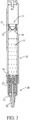
- a writing tool in accordance with the present invention comprises a pen tube 10, a nib assembly 20, and a pressure regulating device 30 that is able to regulate air pressure.
- the writing tool in accordance with the present invention is a writing tool that directly supplies ink and may be, but not limited to, a marker pen, a whiteboard pen, or the like.
- the pen tube 10 has an interior space, an open end, and a vent hole.
- the open end and the vent hole are located at two opposite ends of the pen tube 10, respectively.
- a diameter of the pen tube 10 ranges from, but not limited to, 4 mm to 25 mm.
- the nib assembly 20 is mounted to the open end of the pen tube 10.
- the nib assembly 20 includes a nib housing 21, a nib 22, an internal wadding 23, and a nib holder 24.
- the nib housing 21 is mounted to the open end of the pen tube 10 and has an inner end extending into the pen tube 10.
- the nib 22 is mounted in the nib housing 21 and has an end extending out of the nib housing 21.
- the internal wadding 23 is mounted in the nib housing 21 and around another end of the nib 22.
- the nib holder 24 is mounted to the inner end of the nib housing 21, inserted into the internal wadding 23, and securely holds the internal wadding 23.
- Detailed structure and structural relationships of the nib assembly 20 are conventional and not limited to the above-mentioned ones.
- the pressure regulating device 30 is slidably mounted in the pen tube 10 and divides the interior space of the pen tube 10 into an external communication chamber 11 and an internal chamber 12.
- the internal chamber 12 is disposed closer to the nib assembly 20 than the external communication chamber 11 and is filled with ink and air.
- the external communication chamber 11 communicates with an exterior of the pen tube 10 via the vent hole.
- the pressure regulating device 30 includes a tubular member 31 and a deformable member 32.
- the tubular member 31 is provided with an outer periphery abutting on an inner sidewall of the pen tube 10.
- the outer periphery of the tubular member 31 includes an outer sidewall and two annular flanges 311.
- the annular flanges 311 are spaced from each other, are formed around and protrude from the outer sidewall of the outer periphery of the tubular member 31, and abut on the inner sidewall of the pen tube 10.
- the annular flanges 311 are disposed adjacent to two opposite open ends of the tubular member 31, respectively.
- the tubular member 31 is not structurally limited to the above-mentioned one.
- the annular flanges 311 could be omitted, and the tubular member 31 can make its outer sidewall or other structures directly abut on the inner sidewall of the pen tube 10.
- the deformable member 32 is a diaphragm and disposed in the tubular member 31.
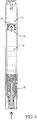
- an air pressure in the internal chamber 12 of the pen tube 10 is larger than the air pressure in the external communication chamber 11
- the deformable member 32 will deform toward the external communication chamber 11, as shown in Fig. 4
- the pressure difference between the internal chamber 12 and the external communication chamber 11 is larger than a second predetermined value
- the whole pressure regulating device 30 will slide relative to the pen tube 10 toward the external communication chamber 11, as shown in Fig. 5 , wherein the second predetermined value is larger than the first predetermined value.
- the deformable member 32 may have alternative structures which can achieve the above-mentioned effects. For example, there are two configurations for the deformable member 32 as recited below.
- the deformable member 32, 32A of the first configuration protrudes toward the internal chamber 12 or protrudes toward the external communication chamber 11 as the air pressure varies. More precisely, when the pressure difference between the internal chamber 12 and the external communication chamber 11 is smaller than the first predetermined value, the deformable member 32, 32A protrudes toward the internal chamber 12; when the pressure difference between the internal chamber 12 and the external communication chamber 11 is larger than the first predetermined value, the deformable member 32, 32A protrudes toward the external communication chamber 11.
- the deformable member 32 may be hemispherical in shape and a direction in which the hemispherical deformable member 32 protrudes varies with the circumstances mentioned in the previous paragraph.
- the deformable member 32A may have a first piece 321A and a second piece 322A. An end of the first piece 321A is connected to an end of the second piece 322A. Another end of the first piece 321A is connected to an inner sidewall of the tubular member 31A. Another end of the second piece 322A is formed as a closed end. An inner diameter of the first piece 321A is larger than that of the second piece 322A. As shown in Fig. 10 , when the deformable member 32A protrudes toward the internal chamber 12, both the first piece 321A and the second piece 322A protrude toward the internal chamber 12. As shown in Fig. 9 , when the deformable member 32A protrudes toward the external communication chamber 11, both the first piece 321A and the second piece 322A protrude toward the external communication chamber 11.
- an inner space enclosed by the deformable member 32B, 32C volumetrically varies with the air pressure. More precisely, the deformable member 32B, 32C keeps protruding toward the external communication chamber 11 and encloses said inner space.
- the deformable member 32B, 32C deforms to expand toward the external communication chamber 11, such that the inner space in this state is volumetrically larger than the inner space when the pressure difference between the internal chamber 12 and the external communication chamber 11 is smaller than the first predetermined value.
- the deformable member 32B, 32C shrinks; when the pressure difference between the internal chamber 12 and the external communication chamber 11 is larger than the first predetermined value, the deformable member 32B, 32C expands.
- the second configuration of the deformable member 32B, 32C includes the following two embodiments.
- the deformable member 32B may be a resilient bag that can be expanded by air pressure. As shown in Fig. 13 , when the pressure difference between the internal chamber 12 and the external communication chamber 11 is smaller than the first predetermined value, the deformable member 32B shrinks. As shown in Fig. 12 , when the pressure difference between the internal chamber 12 and the external communication chamber 11 is larger than the first predetermined value, the deformable member 32B expands toward the external communication chamber 11.
- the deformable member 32C is formed as a tubular bellows. An end of the deformable member 32C is connected to the inner sidewall of the tubular member 31C. Another end of the deformable member 32C is formed as a closed end. As shown in Fig. 16 , when the pressure difference between the internal chamber 12 and the external communication chamber 11 is smaller than the first predetermined value, the deformable member 32C is compressed and shortened. As shown in Fig. 15 , when the pressure difference between the internal chamber 12 and the external communication chamber 11 is larger than the first predetermined value, the deformable member 32C expands and elongates.
- All of the deformable members 32, 32A, 32B, 32C of the four aforementioned embodiments can slightly regulate the air pressure by their deformation toward the external communication chamber 11 when the pressure difference between the internal chamber 12 and the external communication chamber 11 is larger than the first predetermined value.
- the deformable members 32, 32A, 32B, 32C are not limited to the aforementioned two configurations and four embodiments as long as the aforementioned objective of the present invention can be achieved.
- the diameter of the widest part of the deformable member 32 ranges from 5 mm to 10 mm, and the thickness of the deformable member 32 ranges from 0.35 mm to 0.8 mm.
- the size of the deformable member 32 is not limited to the above-mentioned ranges and can be adjusted as needed.
- the deformable member 32 is made of silicon rubber.
- a material that the deformable member 32 is made of is, but not limited to, silicon rubber.
- the deformable member 32 may be made of any material that is able to achieve the above-mentioned effect of the present invention.
- the first predetermined value and the second predetermined value can be defined by external temperature variations in addition to the air pressure difference.
- the external temperature variation that corresponds to the first predetermined value ranges from 2°C to 4°C, and is preferably 3°C;
- the external temperature variation that corresponds to the second predetermined value ranges from 5°C to 7°C, and is preferably 6°C.
- the pressure difference between the internal chamber 12 and the external communication chamber 11 can reach the first predetermined value; when the external temperature rises from 18°C to 24°C, the pressure difference can reach the second predetermined value.
- the pressure difference between the internal chamber 12 and the external communication chamber 11 can reach the first predetermined value; when the external temperature rises from 25°C to 31°C, the pressure difference can reach the second predetermined value.
- the deformable member 32 is pressurized in advance, thereby enabling the deformable member 32 for resistance against its deformation toward the external communication chamber 11.
- the pressure regulating device 30 is pressurized to allow the deformable member 32, 32A to protrude toward the internal chamber 12.
- the writing tool can be transported in such a state that the internal and external air pressures are balanced therebetween, and the influence resulting from the external temperature and the air pressure can be reduced to a minimum degree.
- the pen cap 40 will not be detached or ejected from the pen tube 10 due to the air pressure variation caused by shocks and vibrations during transportation.
- the ink will not be overly dispensed for leakage, such that goods will not be stained and remain intact.
- the pressure regulating device 30 for the writing tool of the present invention can regulate the air pressure inside the pen tube 10 of the writing tool for balance of the air pressure so as to avoid internal air pressure imbalance caused by an external high temperature or an external low air pressure. Accordingly, ink inside the internal chamber 12 will neither spout out upon removal of the pen cap 40 and nor be overly dispensed or leak during writing.
Landscapes
- Engineering & Computer Science (AREA)
- Mechanical Engineering (AREA)
- Pens And Brushes (AREA)
Applications Claiming Priority (1)
| Application Number | Priority Date | Filing Date | Title |
|---|---|---|---|
| TW106138887A TWI641506B (zh) | 2017-11-10 | 2017-11-10 | 書寫具的壓力調整裝置及具有該壓力調整裝置的書寫具 |
Publications (1)
| Publication Number | Publication Date |
|---|---|
| EP3482970A1 true EP3482970A1 (de) | 2019-05-15 |
Family
ID=62110998
Family Applications (1)
| Application Number | Title | Priority Date | Filing Date |
|---|---|---|---|
| EP18170575.7A Withdrawn EP3482970A1 (de) | 2017-11-10 | 2018-05-03 | Druckregelvorrichtung für ein schreibgerät und schreibgerät mit solch einer vorrichtung |
Country Status (5)
| Country | Link |
|---|---|
| US (1) | US10414201B2 (de) |
| EP (1) | EP3482970A1 (de) |
| CN (1) | CN109774347A (de) |
| CA (1) | CA3003852A1 (de) |
| TW (1) | TWI641506B (de) |
Families Citing this family (1)
| Publication number | Priority date | Publication date | Assignee | Title |
|---|---|---|---|---|
| CN110959979A (zh) * | 2020-02-20 | 2020-04-07 | 赵鋕豪 | 一种自动调节气压防漏水液体眼线笔 |
Citations (7)
| Publication number | Priority date | Publication date | Assignee | Title |
|---|---|---|---|---|
| US2143601A (en) * | 1936-06-09 | 1939-01-10 | Iversen Johannes | Fountain pen |
| GB503994A (en) * | 1938-03-17 | 1939-04-18 | Julius Theodoor Citroen | Fountain pen |
| LU28632A1 (fr) * | 1946-05-13 | 1947-12-24 | Perfectionnemts aux instrumants d'écriture à réservoir | |
| FR933116A (fr) * | 1946-08-30 | 1948-04-12 | Stylographe avec système de remplissage perfectionné | |
| US2670710A (en) * | 1949-07-12 | 1954-03-02 | Nahum A Bernstein | Writing instrument |
| FR1058192A (fr) * | 1952-06-10 | 1954-03-15 | Piston obturateur et suiveur pour appareil scripteur à bille | |
| WO2016062972A1 (fr) * | 2014-10-24 | 2016-04-28 | Societe Bic | Membrane de compensation de difference de pression |
Family Cites Families (16)
| Publication number | Priority date | Publication date | Assignee | Title |
|---|---|---|---|---|
| GB191506487A (en) * | 1915-04-30 | 1915-12-09 | Clifford Pressland | Improvements in connection with Fountain Pens. |
| BE479358A (de) * | 1945-04-19 | |||
| LU29633A1 (de) * | 1948-07-15 | |||
| US3854826A (en) * | 1973-12-26 | 1974-12-17 | Artex Hobby | Fluid applicator pressure control device |
| JPS57148659A (en) * | 1981-03-10 | 1982-09-14 | Pilot Pen Co Ltd:The | Fluid discharge device |
| DE3772608D1 (de) | 1986-04-10 | 1991-10-10 | Jiro Hori | Geraet, zum beispiel schreibstift, zum aufbringen von fluessigkeit. |
| JP2679918B2 (ja) * | 1992-02-17 | 1997-11-19 | 二郎 堀 | 筆記具 |
| DE9305608U1 (de) | 1993-04-14 | 1994-08-18 | W.L. Gore & Associates Gmbh, 85640 Putzbrunn | Füllfederhalter |
| JPH1178350A (ja) | 1997-09-10 | 1999-03-23 | Jiro Hori | 筆記具 |
| DE19832046A1 (de) | 1998-07-16 | 2000-02-03 | Dataprint R Kaufmann Gmbh | Gerät zum Auftragen von Flüssigkeiten, insbesondere Schreibgerät |
| DE60126075D1 (de) * | 2000-04-25 | 2007-03-08 | Pentel Kk | Auftragsvorrichtung |
| US7637680B2 (en) * | 2003-11-07 | 2009-12-29 | Sakura Color Products Corporation | Coating tool |
| CN201405605Y (zh) * | 2009-05-11 | 2010-02-17 | 盛义雄 | 环保可擦油笔 |
| JP5890322B2 (ja) * | 2010-01-28 | 2016-03-22 | ルカ マラグティ,ジャン | 万年筆 |
| KR20150133841A (ko) * | 2013-03-27 | 2015-11-30 | 가부시키가이샤 사쿠라 크레파스 | 도포구 |
| TWM557680U (zh) * | 2017-11-10 | 2018-04-01 | Sdi Corp | 書寫具的壓力調整裝置及具有該壓力調整裝置的書寫具 |
-
2017
- 2017-11-10 TW TW106138887A patent/TWI641506B/zh not_active IP Right Cessation
- 2017-12-05 CN CN201711269690.0A patent/CN109774347A/zh active Pending
-
2018
- 2018-04-13 US US15/952,847 patent/US10414201B2/en not_active Expired - Fee Related
- 2018-05-03 EP EP18170575.7A patent/EP3482970A1/de not_active Withdrawn
- 2018-05-03 CA CA3003852A patent/CA3003852A1/en not_active Abandoned
Patent Citations (7)
| Publication number | Priority date | Publication date | Assignee | Title |
|---|---|---|---|---|
| US2143601A (en) * | 1936-06-09 | 1939-01-10 | Iversen Johannes | Fountain pen |
| GB503994A (en) * | 1938-03-17 | 1939-04-18 | Julius Theodoor Citroen | Fountain pen |
| LU28632A1 (fr) * | 1946-05-13 | 1947-12-24 | Perfectionnemts aux instrumants d'écriture à réservoir | |
| FR933116A (fr) * | 1946-08-30 | 1948-04-12 | Stylographe avec système de remplissage perfectionné | |
| US2670710A (en) * | 1949-07-12 | 1954-03-02 | Nahum A Bernstein | Writing instrument |
| FR1058192A (fr) * | 1952-06-10 | 1954-03-15 | Piston obturateur et suiveur pour appareil scripteur à bille | |
| WO2016062972A1 (fr) * | 2014-10-24 | 2016-04-28 | Societe Bic | Membrane de compensation de difference de pression |
Also Published As
| Publication number | Publication date |
|---|---|
| US20190143739A1 (en) | 2019-05-16 |
| TWI641506B (zh) | 2018-11-21 |
| CN109774347A (zh) | 2019-05-21 |
| US10414201B2 (en) | 2019-09-17 |
| CA3003852A1 (en) | 2019-05-10 |
| TW201918385A (zh) | 2019-05-16 |
Similar Documents
| Publication | Publication Date | Title |
|---|---|---|
| AU2018100775A4 (en) | Pressure regulating device for writing tool and writing tool having the same | |
| US20250116520A1 (en) | Inertial measurement module, shock absorption system, and unmanned aerial vehicle | |
| US10414201B2 (en) | Pressure regulating device for writing tool and writing tool having the same | |
| WO2005123416A1 (ja) | 液体供給装置 | |
| US2874679A (en) | Fountain pen construction | |
| US8544762B1 (en) | Thermo-element and thermostat | |
| US6357943B1 (en) | Ball-point pen with correction supply | |
| JP6596273B2 (ja) | 塗布容器 | |
| US6293666B1 (en) | Ink-jet cartridge with pressure adjustment device | |
| US6595046B2 (en) | Temperature and pressure compensating indicator | |
| US2725749A (en) | Pressure gage protector | |
| US3224264A (en) | Pressure indicating device | |
| US7009505B2 (en) | Tire pressure gauge | |
| JP2014046950A (ja) | 吐出容器 | |
| JPH0214200B2 (de) | ||
| US10517369B2 (en) | Drawing apparatus and control method of drawing apparatus | |
| CA2999481C (en) | Temperature control device and process control apparatus including a temperature control device | |
| CN214386084U (zh) | 一种防漏液烟弹及电子雾化装置 | |
| US3234917A (en) | Seal for reservoirs of writing and other dispensing instruments | |
| US3837355A (en) | Apparatus for bleeding metered increments of a compressed gas from a container | |
| TH14869A3 (th) | อุปกรณ์เพื่อการคุมค่าความดันสำหรับเครื่องมือเพื่อการเขียนและเครื่องมือเพื่อการเขียนที่มีสิ่งเดียวกันนี้ | |
| TH14869C3 (th) | อุปกรณ์เพื่อการคุมค่าความดันสำหรับเครื่องมือเพื่อการเขียนและเครื่องมือเพื่อการเขียนที่มีสิ่งเดียวกันนี้ | |
| US2471514A (en) | Safety type thermostat | |
| JP2679952B2 (ja) | 筆記具 | |
| JP2019086124A (ja) | エアダンパーおよびこれを用いた画像形成装置並びに給紙カセット |
Legal Events
| Date | Code | Title | Description |
|---|---|---|---|
| PUAI | Public reference made under article 153(3) epc to a published international application that has entered the european phase |
Free format text: ORIGINAL CODE: 0009012 |
|
| AK | Designated contracting states |
Kind code of ref document: A1 Designated state(s): AL AT BE BG CH CY CZ DE DK EE ES FI FR GB GR HR HU IE IS IT LI LT LU LV MC MK MT NL NO PL PT RO RS SE SI SK SM TR |
|
| AX | Request for extension of the european patent |
Extension state: BA ME |
|
| 17P | Request for examination filed |
Effective date: 20191031 |
|
| RBV | Designated contracting states (corrected) |
Designated state(s): AL AT BE BG CH CY CZ DE DK EE ES FI FR GB GR HR HU IE IS IT LI LT LU LV MC MK MT NL NO PL PT RO RS SE SI SK SM TR |
|
| 17Q | First examination report despatched |
Effective date: 20200515 |
|
| STAA | Information on the status of an ep patent application or granted ep patent |
Free format text: STATUS: THE APPLICATION IS DEEMED TO BE WITHDRAWN |
|
| 18D | Application deemed to be withdrawn |
Effective date: 20201126 |