EP3482475B1 - Steuerungssystem und -verfahren für einen elektrischen aktuator mit ausfallsicherungsfunktionalität - Google Patents
Steuerungssystem und -verfahren für einen elektrischen aktuator mit ausfallsicherungsfunktionalität Download PDFInfo
- Publication number
- EP3482475B1 EP3482475B1 EP17742676.4A EP17742676A EP3482475B1 EP 3482475 B1 EP3482475 B1 EP 3482475B1 EP 17742676 A EP17742676 A EP 17742676A EP 3482475 B1 EP3482475 B1 EP 3482475B1
- Authority
- EP
- European Patent Office
- Prior art keywords
- motor
- control module
- motor control
- energy
- fail
- Prior art date
- Legal status (The legal status is an assumption and is not a legal conclusion. Google has not performed a legal analysis and makes no representation as to the accuracy of the status listed.)
- Active
Links
Images
Classifications
-
- H—ELECTRICITY
- H02—GENERATION; CONVERSION OR DISTRIBUTION OF ELECTRIC POWER
- H02P—CONTROL OR REGULATION OF ELECTRIC MOTORS, ELECTRIC GENERATORS OR DYNAMO-ELECTRIC CONVERTERS; CONTROLLING TRANSFORMERS, REACTORS OR CHOKE COILS
- H02P29/00—Arrangements for regulating or controlling electric motors, appropriate for both AC and DC motors
- H02P29/02—Providing protection against overload without automatic interruption of supply
- H02P29/032—Preventing damage to the motor, e.g. setting individual current limits for different drive conditions
-
- H—ELECTRICITY
- H02—GENERATION; CONVERSION OR DISTRIBUTION OF ELECTRIC POWER
- H02K—DYNAMO-ELECTRIC MACHINES
- H02K11/00—Structural association of dynamo-electric machines with electric components or with devices for shielding, monitoring or protection
- H02K11/30—Structural association with control circuits or drive circuits
- H02K11/33—Drive circuits, e.g. power electronics
-
- F—MECHANICAL ENGINEERING; LIGHTING; HEATING; WEAPONS; BLASTING
- F16—ENGINEERING ELEMENTS AND UNITS; GENERAL MEASURES FOR PRODUCING AND MAINTAINING EFFECTIVE FUNCTIONING OF MACHINES OR INSTALLATIONS; THERMAL INSULATION IN GENERAL
- F16K—VALVES; TAPS; COCKS; ACTUATING-FLOATS; DEVICES FOR VENTING OR AERATING
- F16K31/00—Actuating devices; Operating means; Releasing devices
- F16K31/02—Actuating devices; Operating means; Releasing devices electric; magnetic
- F16K31/04—Actuating devices; Operating means; Releasing devices electric; magnetic using a motor
-
- H—ELECTRICITY
- H02—GENERATION; CONVERSION OR DISTRIBUTION OF ELECTRIC POWER
- H02J—ELECTRIC POWER NETWORKS; CIRCUIT ARRANGEMENTS OR SYSTEMS FOR SUPPLYING OR DISTRIBUTING ELECTRIC POWER; SYSTEMS FOR STORING ELECTRIC ENERGY
- H02J9/00—Circuit arrangements for emergency or stand-by power supply, e.g. for emergency lighting
- H02J9/04—Circuit arrangements for emergency or stand-by power supply, e.g. for emergency lighting in which the distribution system is disconnected from the normal source and connected to a standby source
- H02J9/06—Circuit arrangements for emergency or stand-by power supply, e.g. for emergency lighting in which the distribution system is disconnected from the normal source and connected to a standby source with automatic change-over, e.g. UPS systems
- H02J9/061—Circuit arrangements for emergency or stand-by power supply, e.g. for emergency lighting in which the distribution system is disconnected from the normal source and connected to a standby source with automatic change-over, e.g. UPS systems for DC powered loads
-
- H—ELECTRICITY
- H02—GENERATION; CONVERSION OR DISTRIBUTION OF ELECTRIC POWER
- H02K—DYNAMO-ELECTRIC MACHINES
- H02K11/00—Structural association of dynamo-electric machines with electric components or with devices for shielding, monitoring or protection
- H02K11/0094—Structural association with other electrical or electronic devices
-
- H—ELECTRICITY
- H02—GENERATION; CONVERSION OR DISTRIBUTION OF ELECTRIC POWER
- H02K—DYNAMO-ELECTRIC MACHINES
- H02K2213/00—Specific aspects, not otherwise provided for and not covered by codes H02K2201/00 - H02K2211/00
- H02K2213/06—Machines characterised by the presence of fail safe, back up, redundant or other similar emergency arrangements
Definitions
- the present invention relates to a control system for an electric actuator including a fail-safe function. More specifically, the present invention relates to a control system for an electric actuator comprising an electric motor, an external supply of electric energy, a chargeable energy storage device and a first motor control module which controls the supply of energy to the motor in normal operation. The invention also relates to a control method providing fail-safe functionality in an electric actuator.
- US 6 257 549 B1 discloses a wellhead provided with a valve tree such as a Christmas tree. To operate a valve, an electrical processor and controller sends a signal to a fail-safe controller.
- US 2011/215747 A1 discloses an electric actuator used in air-conditioning equipment.
- US5144153A discloses a motorized gate.
- EP 0 695 918 A1 discloses moving hinged glass vents by means of electric motors powered by batteries.
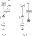
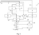
- Figs. 1 and 2 show examples of known fail-safe systems for valves that are used subsea.
- Fig. 1 shows a control system wherein fail-safe functionality is based on software code and input command (CMD) which can be released in connection with a process shutdown (PSD). It can be a complicated and cumbersome process to obtain and update an acceptable level of security in a software based fail-safe system.
- Fig. 2 shows a system wherein fail-safe functionality is based on a spring that drives the valve into fail-safe position upon request of a process shutdown.
- a spring based system can be complicated to implement with rotating multi-turn actuators.
- a spring based system can be space consuming which again leads to larger overall structures.
- a battery in connection with the anti-lock braking system, e.g. using batteries in safety systems and in systems that require uptime or uninterrupted operation is known.
- batteries for example, the telecommunication industry uses batteries as emergency power supply. It is also known to use battery operated UPS (uninterruptible power supply) for emergency operation.
- UPS uninterruptible power supply
- the present invention provides a subsea control system for an electric actuator comprising an electric motor, an external supply of electric energy, a chargeable energy storage device and a first motor control module which controls the supply of energy to the motor in normal operation.
- a second motor control module powered by the energy storage device and which controls the supply of energy to the motor in fail-safe mode is arranged, wherein the first motor control module and the second motor control module are connected in parallel via a fail-safe switch which is arranged to override the control executed by the first motor control module to set the control system in fail-safe mode by activation of the second motor control module in case of the energy level in the energy storage device reaching, or falling below, a predetermined value.
- the first motor control module is arranged for controlling the supply of energy to the motor by executing software coded instructions
- the second motor control module is arranged for controlling the supply of energy to the motor as pre-determined by built-in functionality of its components.
- the present invention provides a robust fail-safe functionality which operates independently from control software.
- a motor drive module is arranged for modulation of the energy supplied to the motor according to input from the software implemented first motor control module in normal operation, or according to input from the hardware operated second motor control module in fail-safe mode.
- a Hall sensor is arranged to detect the rotary position of the motor or the rotary position of a motor shaft.
- a resolver module is arranged to detect the position of a gear transmission that is arranged for converting the rotation of the motor to a rotary or linear motion.
- the invention thereby relates to a control system comprising a fail-safe function activated as a function of energy level in the energy storage device or as a function of loss of energy supply or in response to an operator command.
- the control system comprises a motor control module, powered from an energy storage device, that switches on and runs the motor into a safe position in a case of emergency.
- a case of emergency occurs e.g. if the voltage level of the energy storage device is below a predefined threshold value or if external energy supply to the control system is lost.
- a triggering signal is either removed or generated, as the case may be (i.e. equivalent to an emergency stop).
- This motor control module uses a dedicated hardware motor control circuit to run the motor into a fail-safe position. As the system is using a separate hardware circuit to control the motor into fail-safe mode, it is not necessary to account for software updates and the like.
- the hardware motor control circuit in the motor control module is electronically driven.
- the valve control system may comprise an energy storage device being a battery.
- the valve control system may comprise an energy storage device being a super capacitor.
- the pre-determined fail-safe functionality of the control system makes it useful for installation subsea.
- the control system of the invention is useful in subsea valve applications.
- Other alternative applications include, without limitation, gates or doors or hatches, pistons or bolts, circuit breakers, shunts or switches, etc., which may need to be moved from an operative mode into a safety mode in response to a given process parameter.
- control system as outlined above permits the implementation of a new control method for an electric actuator in a subsea control system. This method comprises:
- Embodiments of the method include configuring the second motor control module with solid state or semiconductor components having pre-determined built-in functionality.
- Embodiments of the method include configuring the first motor control module for execution of software coded instructions.
- Other embodiments include arranging a motor drive module for modulation of energy supplied to the motor in response to input commands from either of the first or second motor control modules, separated in the fail-safe switch.
- FIG. 3 there is shown a control system 1 for an electric actuator wherein electrical energy is stored in an energy storage device 2, the energy being used to drive a mechanism that controls the position of a valve stem in a valve 3.
- a motor 4 is operatively connected to the valve 3 via a gear transmission 5.
- the motor can be an induction motor or a brushless direct current (BLDC) or alternating current (BLAC) motor.
- the gear transmission 5 is arranged for conversion of the rotating movement of the motor to the torque and direction required for regulation of the position of the valve 3 between open and closed positions.
- the opening or closing movement may be linear or rotating as required in a gate valve or in a choke valve, whichever is appropriate for a given application.
- the release of energy to the motor is controlled by a set of modules comprising various mechanical and electronic components. These components are configured in such a way as to drive the motor in a controlled fashion to a pre-determined state and/or position.
- the electronic components have a defined level of reliability that ensures the required availability of the system which the electric valve actuator is a part of.
- the electronic components may be testable to verify that the functionality is present.
- the control system 1 further comprises a power management (PM) and charger module 6.
- the PM/charger module 6 receives energy from an external source via a power input line 7, and transforms this energy to be usable within the control system for charging the energy storage device 2.
- the PM/charger module 6 may be arranged to receive DC input power from a subsea control module (SCM, not shown in Fig. 3 ).
- SCM subsea control module
- the PM/charger module 6 may alternatively contain e.g. an AC/DC converter and a transformer arranged for transformation of input power into a voltage and current suitable as charging power.
- the energy storage device 2 is realized in the form of an accumulator (battery or capacitor).
- the energy storage device 2 thus stores energy and supplies this energy, on demand, to modules and devices of the control system 1.
- the internal distribution of energy to the motor 4 for actuation is delivered from the energy storage device 2, as illustrated in Fig. 3 by double-drawn lines 8.
- the internal energy distribution may alternatively include by-passing of the energy storage device 2 for a direct delivery of energy from the PM/charger module 6 to the motor 4 via a motor drive module 16.
- a system control module 9 contains software coded instructions for receiving and executing commands from an external device (subsea or topside, not shown in Fig. 3 ) via communication line 10.
- the system control module 9 is further arranged for reporting detected sensor data and status of the valve or the valve actuator back to the external device.
- the commands received in the system control module 9 are distributed to the relevant subsystems through an internal communication network 11, by which system status data can likewise be returned from the subsystems to the system control module 9.
- the system control module 9 may be arranged to support any available type of communication protocol towards external and internal, subsea or topside, modules and devices.
- the system control module 9 can be arranged for external communication via any suitable communication interface such as RS-485, CAN bus (SIIS-level-2) or Ethernet, for example.
- External communication may include e.g. communication with a subsea electronic module (SEM), not shown in the drawing.
- SEM subsea electronic module
- the control system 1 furthermore comprises a software implemented, first motor control module 12.
- the first motor control module 12 receives commands from the system control module 9 to run the motor, and ensures that the motor is operated according to the commands by controlling the level of energy delivered to the motor from the energy storage device 2.
- the first motor control module 12 is a software based controller, the operation of which is dictated by software code.
- the control system 1 further comprises a fail-safe switch 13.
- the fail-safe switch 13 either receives or loses a signal from an external device, and upon this change in signal status, the switch 13 ensures that the first motor control module 12 is isolated from the actuator control, the first motor control module 12 thus no longer being able to execute control of the actuator (i.e. powering of the motor and controlling the position of for example a valve).
- the external device for setting the fail-safe switch 13 in fail-safe mode can be an operator command 14.
- the fail-safe switch 13 further receives a signal or a signal status change from a second motor control module 15 for fail-safe (SIL, Safety Integrity Level) function.
- the second motor control module 15 comprises a hardware motor control circuit which, in a pre-determined way, controls the energy delivered to the motor 4 from the energy storage device 2.
- the pre-configured function includes a dedicated use of the energy remaining in the energy storage device 2 after reach or passage of a capacity threshold value, or a dedicated use of the energy in the energy storage device 2 after loss of external energy 7. This pre-configured function is thus not dependent on the software that is normally used to control the motor via the first motor control module 12.
- the second motor control module 15 is an integrated circuit that comprises semiconductor components with built-in functionality.
- a "hardware motor control circuit” is to be understood briefly as a motor controller, the operation of which is determined by the structure and built-in functionality of solid state or semiconductor components, rather than a motor controller the operation of which is dictated by software code.
- the hardware motor control circuit may include semiconductor relays and switches in the second motor control module 15.
- the second motor control module 15 can be setup to deliver to the motor 4 a pre-determined torque and motor rotation direction as long as there is energy left in the energy storage device 2 (battery or capacitor).
- the fail-safe switch 13 carries out a pre-determined function that overrides the software coded instructions implemented in the first motor control module 12.
- the fail-safe switch 13 is a selector which is triggered by either certain energy levels or manually or particular safety mode software command in order to shift from software operated motor control to hardware operated motor control.
- Examples of events that will trigger the safety function include e.g. loss of energy supply (possibly with a delay to preclude false events), or upon reach or passage of a minimum level of energy in the energy storage device 2 required to drive the valve to safe position.
- the control system 1 further comprises a motor drive module 16 which modulates the energy coming from the energy storage device 2 via line 8 and being supplied to the motor 4 via an energy supply line 17.
- the motor drive module 16 applies the energy to the motor 4, either according to signal input 19 from the software implemented first motor control module 12 in normal operation, or according to signal input 20 from the hardware operated second motor control module 15 for SIL function in fail-safe mode, or according to operator command 14 signal input.
- the signal input commands 14, 19, 20 are routed to the motor drive module 16 via the fail-safe switch 13 and a signal line 18.
- the fail-safe switch 13 thus blocks the signal path 19 from the first motor control module 12 if it receives, or loses, a signal from the second motor control module 15 via signal path 20. Accordingly, the first motor control module 12 and the second motor control module 15 control, separately and individually, the supply of energy to the motor 4 in dependence on the position of the fail-safe switch 13.
- the motor drive module 16 may be arranged for regulation of rotational direction, torque and speed of the motor 4. If the motor 4 is realized as a BLDC motor for example, the motor drive module 16 may include a current controller for regulation of torque, and a speed controller for regulation of amplitude in the applied voltage. Thus, without limitation hereto, the motor drive module 16 may comprise a pulse width modulation module, an analogue-to-digital converter, timer, communication peripherals, etc., as known in the art of digital signal controllers.
- Operating status of the motor drive module 16 can be reported back to the first and second motor control modules 12 and 15 via feedback signal lines 21 and 22.
- the status and energy level in the energy storage device 2 can be reported, via the internal communication network 11, for monitoring by the second motor control module 15, as illustrated through dotted lines in Fig. 3 .
- the motor drive module 16 can alternatively be the physical means which monitors the level of available energy that can be delivered from the energy storage device 2. The status of the energy storage device 2 may then be reported to the first and second motor control modules 12 and 15 via the signal lines 21, 22.
- the first motor control module 12, the second motor control module 15 and the fail-safe switch 13 may in practise be incorporated on the same circuit board.
- a Hall sensor 23 can be arranged to detect the position of the rotating parts of the motor 4 or the motor shaft 24, and transmitting this information to the first motor control module 12 via a signal line 25 for implementation in the motor drive module 16 via input 19 to the fail-safe switch 13.
- a resolver module 26 can be arranged to detect the rotary or linear position of the gear transmission 5, and transmitting this information to the first motor control module 12 via the signal line 25 for implementation in the motor drive module 16 via input 19 to the fail-safe switch 13.
- valve control system and method provides several advantages, such as:
- the invention can be successfully applied to an electric valve actuator in a subsea installation. It will also be readily appreciated that the invention can likewise be successfully applied to an electric actuator for a gate, a piston, a ball valve, a plug valve or a circuit breaker, etc.
Landscapes
- Engineering & Computer Science (AREA)
- General Engineering & Computer Science (AREA)
- Power Engineering (AREA)
- Mechanical Engineering (AREA)
- Business, Economics & Management (AREA)
- Emergency Management (AREA)
- Microelectronics & Electronic Packaging (AREA)
- Safety Devices In Control Systems (AREA)
- Control Of Electric Motors In General (AREA)
Claims (12)
- Unterwassersteuersystem (1) für einen elektrischen Aktuator, umfassend einen elektrischen Motor (4), eine externe Zufuhr (7) von elektrischer Energie, eine Energiespeichervorrichtung (2) und ein erstes Motorsteuermodul (12), das angepasst ist, um die Energiezufuhr an den Motor (4) in einem Normalbetrieb zu steuern, gekennzeichnet durch ein zweites Motorsteuermodul (15), das durch die Energiespeichervorrichtung (2) mit Leistung versorgt wird und angepasst ist, um die Energiezufuhr an den Motor (4) in einem ausfallsicheren Modus zu steuern, wobei das erste Motorsteuermodul (12) und das zweite Motorsteuermodul (15) über einen ausfallsicheren Schalter (13) parallel verbunden sind, der angeordnet ist, um die Steuerung, die durch das erste Motorsteuermodul (12) ausgeführt wird, außer Kraft zu setzen und das Steuersystem (1) in den ausfallsicheren Modus durch eine Aktivierung des zweiten Motorsteuermoduls (15) zu versetzen, in einem Fall, dass der Energiepegel in der Energiespeichervorrichtung (2) einen zuvor bestimmten Wert erreicht oder unterschreitet.
- System nach Anspruch 1, wobei der ausfallsichere Schalter (13) ferner angeordnet ist, um das Steuersystem (1) durch die Aktivierung des zweiten Motorsteuermoduls (15) in dem Fall eines Ausfalls in der externen Energiezufuhr (7) oder als Reaktion auf einen Bedienerbefehl (14) in den ausfallsicheren Modus zu versetzen.
- System nach Anspruch 1 oder 2, wobei das erste Motorsteuermodul (12) zum Steuern der Energiezufuhr an den Motor (4) durch das Ausführen von softwarecodierten Anweisungen angeordnet ist, während das zweite Motorsteuermodul (15) zum Steuern der Energiezufuhr an den Motor (4) wie zuvor bestimmt durch eine eingebaute Funktionalität seiner Komponenten angeordnet ist.
- System nach einem der Ansprüche 1 bis 3, ferner umfassend ein Motorantriebsmodul (16), das für eine Modulation der Energie, die dem Motor (4) zugeführt wird, gemäß einer Eingabe (19) von dem ersten Motorsteuermodul (12) in dem Normalbetrieb oder gemäß der Eingabe (20) von dem zweiten Motorsteuermodul (15) in dem ausfallsicheren Modus oder gemäß der Eingabe eines Bedienerbefehls (14) angeordnet ist.
- System nach einem der Ansprüche 1 bis 4, wobei der Energiepegelstatus in der Energiespeichervorrichtung (2) durch das zweite Motorsteuermodul (15) überwacht wird.
- System nach einem der Ansprüche 1 bis 5, angewendet auf einen elektrischen Ventilaktuator in einer Unterwasserinstallation.
- System nach einem der Ansprüche 1 bis 5, angewendet auf einen elektrischen Aktuator für ein Tor, einen Kolben, ein Kugelventil, einen Hahn oder einen Trennschalter.
- Verfahren zum Steuern eines elektrischen Aktuators in einem Unterwassersteuersystem (1), umfassend einen elektrischen Motor (4), eine externe Zufuhr (7) von elektrischer Energie, eine Energiespeichervorrichtung (2) und ein erstes Motorsteuermodul (12), das die Energiezufuhr an den Motor (4) in dem Normalbetrieb steuert, wobei das Verfahren gekennzeichnet ist durch die Schritte:Anordnen eines zweiten Motorsteuermoduls (15) parallel zu dem ersten Motorsteuermodul (12), wobei das zweite Motorsteuermodul (15) durch die Energiespeichervorrichtung (2) mit Leistung versorgt wird, Konfigurieren des zweiten Motorsteuermoduls (15), um zum Steuern der Energiezufuhr an den Motor (4) in dem ausfallsicheren Modus wirksam zu sein,Verbinden des ersten (12) und des zweiten (15) Motorsteuermoduls mit dem Motor (4) über einen ausfallsicheren Schalter (13), der auf den überwachten Status der zugeführten Energie reagiert, undUmschalten von der Motorsteuerung durch das erste Motorsteuermodul (12) auf die Motorsteuerung durch das zweite Motorsteuermodul (15) als Reaktion darauf, dass der Energiepegel in der Energiespeichervorrichtung (2) einen zuvor bestimmten Wert erreicht oder unterschreitet.
- Verfahren nach Anspruch 8, wobei der ausfallsichere Schalter (13) ferner angeordnet ist, um das Steuersystem (1) in den ausfallsicheren Modus durch die Aktivierung des zweiten Motorsteuermoduls (15) in dem Fall eines Ausfalls in der externen Energiezufuhr (7) oder als Reaktion auf einen Bedienerbefehl (14) zu versetzen.
- Verfahren nach Anspruch 8 oder 9, ferner umfassend:
Konfigurieren des zweiten Motorsteuermoduls (15) mit Festkörper- oder Halbleiterkomponenten, die eine zuvor bestimmte integrierte Funktionalität aufweisen. - Verfahren nach einem der Ansprüche 8 bis 10, ferner umfassend:
Konfigurieren des ersten Motorsteuerungsmoduls (12) für die Ausführung von softwarecodierten Anweisungen. - Verfahren nach einem der Ansprüche 8 bis 11, ferner umfassend:
Anordnen eines Motorantriebsmoduls (16) für die Modulation von Energie, die dem Motor (4) zugeführt wird, als Reaktion auf Signaleingabebefehle (14, 19, 20) entweder von dem ersten (12) oder dem zweiten (15) Motorsteuerungsmodul oder einem Bediener, getrennt in dem ausfallsicheren Schalter (13).
Applications Claiming Priority (3)
| Application Number | Priority Date | Filing Date | Title |
|---|---|---|---|
| NO20161153 | 2016-07-11 | ||
| NO20171029A NO342871B1 (en) | 2016-07-11 | 2017-06-23 | Control system and method for an electric actuator with fail-safe functionality |
| PCT/EP2017/067290 WO2018011150A1 (en) | 2016-07-11 | 2017-07-10 | Control system and method for an electric actuator with fail-safe functionality |
Publications (2)
| Publication Number | Publication Date |
|---|---|
| EP3482475A1 EP3482475A1 (de) | 2019-05-15 |
| EP3482475B1 true EP3482475B1 (de) | 2025-06-18 |
Family
ID=61094609
Family Applications (1)
| Application Number | Title | Priority Date | Filing Date |
|---|---|---|---|
| EP17742676.4A Active EP3482475B1 (de) | 2016-07-11 | 2017-07-10 | Steuerungssystem und -verfahren für einen elektrischen aktuator mit ausfallsicherungsfunktionalität |
Country Status (4)
| Country | Link |
|---|---|
| US (1) | US10931178B2 (de) |
| EP (1) | EP3482475B1 (de) |
| AU (1) | AU2017295902B2 (de) |
| NO (1) | NO342871B1 (de) |
Families Citing this family (2)
| Publication number | Priority date | Publication date | Assignee | Title |
|---|---|---|---|---|
| US11686757B2 (en) * | 2021-09-14 | 2023-06-27 | Hamilton Sundstrand Corporation | Systems and methods for circuit failure protection |
| US12404736B2 (en) * | 2023-05-16 | 2025-09-02 | Schlumberger Technology Corporation | Electrically-actuated blow-out preventer |
Citations (3)
| Publication number | Priority date | Publication date | Assignee | Title |
|---|---|---|---|---|
| US5144153A (en) * | 1989-10-02 | 1992-09-01 | Automation And Protection Systems, Inc. | Method and apparatus for operating motorized gate upon loss of electrical power thereto |
| EP0695918A1 (de) * | 1994-08-05 | 1996-02-07 | Colt International Holdings A.G. | Sicherheitsvorrichtung |
| US20110215747A1 (en) * | 2010-03-05 | 2011-09-08 | Yamatake Corporation | Electric actuator and module for supplying power during a power failure |
Family Cites Families (11)
| Publication number | Priority date | Publication date | Assignee | Title |
|---|---|---|---|---|
| JPH07251749A (ja) * | 1994-03-16 | 1995-10-03 | Mitsubishi Electric Corp | 電動パワーステアリング制御装置 |
| DE69833091D1 (de) * | 1998-09-03 | 2006-03-30 | Cooper Cameron Corp | Aktivierungsmodul |
| NO312376B1 (no) * | 2000-05-16 | 2002-04-29 | Kongsberg Offshore As | Fremgangsmåte og anordning for styring av ventiler av en undervannsinstallasjon |
| US6488260B1 (en) | 2000-10-10 | 2002-12-03 | Halliburton Energy Services, Inc. | Electric fail safe valve actuator |
| US6998724B2 (en) * | 2004-02-18 | 2006-02-14 | Fmc Technologies, Inc. | Power generation system |
| US7069109B2 (en) * | 2004-11-09 | 2006-06-27 | E.G.O. North America, Inc. | Systems and methods of using multiple microcontrollers for fail-safe control and enhanced feature operation of an appliance |
| DE102006051287A1 (de) * | 2006-10-26 | 2008-04-30 | Getrag Getriebe- Und Zahnradfabrik Hermann Hagenmeyer Gmbh & Cie Kg | Aktuatoranordnung für eine Kraftfahrzeugkupplung |
| SG10201404155XA (en) | 2008-02-27 | 2014-10-30 | Vetco Gray Inc | Detachable electrical actuator |
| JP2013545053A (ja) * | 2010-12-06 | 2013-12-19 | シングル・ブイ・ムアリングス・インコーポレイテッド | 流体管路の弁作動用アクチュエータ |
| GB2489019B (en) | 2011-03-16 | 2017-11-15 | Aker Solutions Ltd | Subsea electric actuators and latches for them |
| NO337300B1 (no) | 2013-04-17 | 2016-03-07 | Fmc Kongsberg Subsea As | Subsea-høyspenningsdistribusjonssystem |
-
2017
- 2017-06-23 NO NO20171029A patent/NO342871B1/en unknown
- 2017-07-10 AU AU2017295902A patent/AU2017295902B2/en active Active
- 2017-07-10 US US16/316,997 patent/US10931178B2/en active Active
- 2017-07-10 EP EP17742676.4A patent/EP3482475B1/de active Active
Patent Citations (3)
| Publication number | Priority date | Publication date | Assignee | Title |
|---|---|---|---|---|
| US5144153A (en) * | 1989-10-02 | 1992-09-01 | Automation And Protection Systems, Inc. | Method and apparatus for operating motorized gate upon loss of electrical power thereto |
| EP0695918A1 (de) * | 1994-08-05 | 1996-02-07 | Colt International Holdings A.G. | Sicherheitsvorrichtung |
| US20110215747A1 (en) * | 2010-03-05 | 2011-09-08 | Yamatake Corporation | Electric actuator and module for supplying power during a power failure |
Also Published As
| Publication number | Publication date |
|---|---|
| AU2017295902A1 (en) | 2019-01-24 |
| EP3482475A1 (de) | 2019-05-15 |
| NO20171029A1 (en) | 2018-01-12 |
| US10931178B2 (en) | 2021-02-23 |
| NO342871B1 (en) | 2018-08-20 |
| AU2017295902B2 (en) | 2020-05-21 |
| BR112018077370A2 (pt) | 2019-07-16 |
| US20190229591A1 (en) | 2019-07-25 |
Similar Documents
| Publication | Publication Date | Title |
|---|---|---|
| RU2614555C2 (ru) | Устройство для техники автоматизации | |
| US10315631B2 (en) | Method for operating a motor vehicle brake system, and a control device for a motor vehicle brake system | |
| CN106660753B (zh) | 模块化的门驱动控制系统以及模块化的门驱动系统 | |
| EP2956394B1 (de) | Sicherheitsschaltung für einen aufzug | |
| CN105583828A (zh) | 用于使工业机器人的轴停止运转的方法和系统 | |
| WO2018011150A1 (en) | Control system and method for an electric actuator with fail-safe functionality | |
| US11715998B2 (en) | Switching device for switching an electric motor | |
| US12421988B2 (en) | Pilot control unit for at least one valve drive of a hydraulic valve and method for operating same | |
| US10931178B2 (en) | Control system and method for an electric actuator with fail-safe functionality | |
| US12074552B2 (en) | Dual encoder system for electric motor | |
| US9103233B2 (en) | Method and apparatus for improving electro-hydraulic and electro-mechanical integrated control systems of a steam turbine | |
| EP3560091A1 (de) | Schliessgeschwindigkeitsregelung beim ausschalten | |
| CN113853664B (zh) | 具有驱动系统的开关装置 | |
| CN117242661A (zh) | 防止海底电子模块掉电的自主方法 | |
| JP7364919B2 (ja) | ブレーキ回路放電システム | |
| CN107650891A (zh) | 具有高级可用性的飞行器制动系统 | |
| US9753513B2 (en) | Actuating drive and method for servicing and/or commissioning an actuating drive | |
| US11996250B2 (en) | Switch assembly with drive system, and method for safely operating a switch assembly | |
| EP3855466B1 (de) | Verlängerung der lebensdauer von steuerschaltungen für elektromagnetische bremsen | |
| BR112018077370B1 (pt) | Sistema de controle para um atuador elétrico e método para controlar um atuador eléctrico de um sistema de controle | |
| Wratil | Technology of safe Drives | |
| KR20220062583A (ko) | 제어기 및 액추에이터, 및 기능 안전을 제공하기 위한 어셈블리를 또한 갖는 시스템 | |
| CN103839709A (zh) | 一种配电网环网柜双电源开关机械联锁系统 | |
| WO2010106562A2 (en) | Communication system between the operators of powered closing devices with two moving parts | |
| US12331487B2 (en) | Device for controlling working unit of construction equipment |
Legal Events
| Date | Code | Title | Description |
|---|---|---|---|
| STAA | Information on the status of an ep patent application or granted ep patent |
Free format text: STATUS: UNKNOWN |
|
| STAA | Information on the status of an ep patent application or granted ep patent |
Free format text: STATUS: THE INTERNATIONAL PUBLICATION HAS BEEN MADE |
|
| PUAI | Public reference made under article 153(3) epc to a published international application that has entered the european phase |
Free format text: ORIGINAL CODE: 0009012 |
|
| STAA | Information on the status of an ep patent application or granted ep patent |
Free format text: STATUS: REQUEST FOR EXAMINATION WAS MADE |
|
| 17P | Request for examination filed |
Effective date: 20190211 |
|
| AK | Designated contracting states |
Kind code of ref document: A1 Designated state(s): AL AT BE BG CH CY CZ DE DK EE ES FI FR GB GR HR HU IE IS IT LI LT LU LV MC MK MT NL NO PL PT RO RS SE SI SK SM TR |
|
| AX | Request for extension of the european patent |
Extension state: BA ME |
|
| DAV | Request for validation of the european patent (deleted) | ||
| DAX | Request for extension of the european patent (deleted) | ||
| STAA | Information on the status of an ep patent application or granted ep patent |
Free format text: STATUS: EXAMINATION IS IN PROGRESS |
|
| 17Q | First examination report despatched |
Effective date: 20220214 |
|
| P01 | Opt-out of the competence of the unified patent court (upc) registered |
Effective date: 20230526 |
|
| GRAP | Despatch of communication of intention to grant a patent |
Free format text: ORIGINAL CODE: EPIDOSNIGR1 |
|
| STAA | Information on the status of an ep patent application or granted ep patent |
Free format text: STATUS: GRANT OF PATENT IS INTENDED |
|
| INTG | Intention to grant announced |
Effective date: 20241216 |
|
| GRAS | Grant fee paid |
Free format text: ORIGINAL CODE: EPIDOSNIGR3 |
|
| GRAA | (expected) grant |
Free format text: ORIGINAL CODE: 0009210 |
|
| STAA | Information on the status of an ep patent application or granted ep patent |
Free format text: STATUS: THE PATENT HAS BEEN GRANTED |
|
| AK | Designated contracting states |
Kind code of ref document: B1 Designated state(s): AL AT BE BG CH CY CZ DE DK EE ES FI FR GB GR HR HU IE IS IT LI LT LU LV MC MK MT NL NO PL PT RO RS SE SI SK SM TR |
|
| REG | Reference to a national code |
Ref country code: GB Ref legal event code: FG4D |
|
| REG | Reference to a national code |
Ref country code: CH Ref legal event code: EP |
|
| REG | Reference to a national code |
Ref country code: DE Ref legal event code: R096 Ref document number: 602017089987 Country of ref document: DE |
|
| REG | Reference to a national code |
Ref country code: CH Ref legal event code: EP |
|
| REG | Reference to a national code |
Ref country code: IE Ref legal event code: FG4D |
|
| PG25 | Lapsed in a contracting state [announced via postgrant information from national office to epo] |
Ref country code: FI Free format text: LAPSE BECAUSE OF FAILURE TO SUBMIT A TRANSLATION OF THE DESCRIPTION OR TO PAY THE FEE WITHIN THE PRESCRIBED TIME-LIMIT Effective date: 20250618 |
|
| PGFP | Annual fee paid to national office [announced via postgrant information from national office to epo] |
Ref country code: DE Payment date: 20250620 Year of fee payment: 9 |
|
| REG | Reference to a national code |
Ref country code: LT Ref legal event code: MG9D |
|
| PG25 | Lapsed in a contracting state [announced via postgrant information from national office to epo] |
Ref country code: NO Free format text: LAPSE BECAUSE OF FAILURE TO SUBMIT A TRANSLATION OF THE DESCRIPTION OR TO PAY THE FEE WITHIN THE PRESCRIBED TIME-LIMIT Effective date: 20250918 Ref country code: GR Free format text: LAPSE BECAUSE OF FAILURE TO SUBMIT A TRANSLATION OF THE DESCRIPTION OR TO PAY THE FEE WITHIN THE PRESCRIBED TIME-LIMIT Effective date: 20250919 |
|
| PG25 | Lapsed in a contracting state [announced via postgrant information from national office to epo] |
Ref country code: BG Free format text: LAPSE BECAUSE OF FAILURE TO SUBMIT A TRANSLATION OF THE DESCRIPTION OR TO PAY THE FEE WITHIN THE PRESCRIBED TIME-LIMIT Effective date: 20250618 |
|
| PGFP | Annual fee paid to national office [announced via postgrant information from national office to epo] |
Ref country code: GB Payment date: 20250724 Year of fee payment: 9 |
|
| PG25 | Lapsed in a contracting state [announced via postgrant information from national office to epo] |
Ref country code: HR Free format text: LAPSE BECAUSE OF FAILURE TO SUBMIT A TRANSLATION OF THE DESCRIPTION OR TO PAY THE FEE WITHIN THE PRESCRIBED TIME-LIMIT Effective date: 20250618 |
|
| PG25 | Lapsed in a contracting state [announced via postgrant information from national office to epo] |
Ref country code: RS Free format text: LAPSE BECAUSE OF FAILURE TO SUBMIT A TRANSLATION OF THE DESCRIPTION OR TO PAY THE FEE WITHIN THE PRESCRIBED TIME-LIMIT Effective date: 20250918 |
|
| REG | Reference to a national code |
Ref country code: NL Ref legal event code: MP Effective date: 20250618 |
|
| PG25 | Lapsed in a contracting state [announced via postgrant information from national office to epo] |
Ref country code: LV Free format text: LAPSE BECAUSE OF FAILURE TO SUBMIT A TRANSLATION OF THE DESCRIPTION OR TO PAY THE FEE WITHIN THE PRESCRIBED TIME-LIMIT Effective date: 20250618 |
|
| PG25 | Lapsed in a contracting state [announced via postgrant information from national office to epo] |
Ref country code: NL Free format text: LAPSE BECAUSE OF FAILURE TO SUBMIT A TRANSLATION OF THE DESCRIPTION OR TO PAY THE FEE WITHIN THE PRESCRIBED TIME-LIMIT Effective date: 20250618 |
|
| PG25 | Lapsed in a contracting state [announced via postgrant information from national office to epo] |
Ref country code: PT Free format text: LAPSE BECAUSE OF FAILURE TO SUBMIT A TRANSLATION OF THE DESCRIPTION OR TO PAY THE FEE WITHIN THE PRESCRIBED TIME-LIMIT Effective date: 20251020 |
|
| REG | Reference to a national code |
Ref country code: AT Ref legal event code: MK05 Ref document number: 1805130 Country of ref document: AT Kind code of ref document: T Effective date: 20250618 |
|
| PG25 | Lapsed in a contracting state [announced via postgrant information from national office to epo] |
Ref country code: IS Free format text: LAPSE BECAUSE OF FAILURE TO SUBMIT A TRANSLATION OF THE DESCRIPTION OR TO PAY THE FEE WITHIN THE PRESCRIBED TIME-LIMIT Effective date: 20251018 |
|
| PG25 | Lapsed in a contracting state [announced via postgrant information from national office to epo] |
Ref country code: AT Free format text: LAPSE BECAUSE OF FAILURE TO SUBMIT A TRANSLATION OF THE DESCRIPTION OR TO PAY THE FEE WITHIN THE PRESCRIBED TIME-LIMIT Effective date: 20250618 Ref country code: SM Free format text: LAPSE BECAUSE OF FAILURE TO SUBMIT A TRANSLATION OF THE DESCRIPTION OR TO PAY THE FEE WITHIN THE PRESCRIBED TIME-LIMIT Effective date: 20250618 |
|
| PG25 | Lapsed in a contracting state [announced via postgrant information from national office to epo] |
Ref country code: CZ Free format text: LAPSE BECAUSE OF FAILURE TO SUBMIT A TRANSLATION OF THE DESCRIPTION OR TO PAY THE FEE WITHIN THE PRESCRIBED TIME-LIMIT Effective date: 20250618 |
|
| PG25 | Lapsed in a contracting state [announced via postgrant information from national office to epo] |
Ref country code: PL Free format text: LAPSE BECAUSE OF FAILURE TO SUBMIT A TRANSLATION OF THE DESCRIPTION OR TO PAY THE FEE WITHIN THE PRESCRIBED TIME-LIMIT Effective date: 20250618 |
|
| PG25 | Lapsed in a contracting state [announced via postgrant information from national office to epo] |
Ref country code: EE Free format text: LAPSE BECAUSE OF FAILURE TO SUBMIT A TRANSLATION OF THE DESCRIPTION OR TO PAY THE FEE WITHIN THE PRESCRIBED TIME-LIMIT Effective date: 20250618 |
|
| PG25 | Lapsed in a contracting state [announced via postgrant information from national office to epo] |
Ref country code: SK Free format text: LAPSE BECAUSE OF FAILURE TO SUBMIT A TRANSLATION OF THE DESCRIPTION OR TO PAY THE FEE WITHIN THE PRESCRIBED TIME-LIMIT Effective date: 20250618 Ref country code: RO Free format text: LAPSE BECAUSE OF FAILURE TO SUBMIT A TRANSLATION OF THE DESCRIPTION OR TO PAY THE FEE WITHIN THE PRESCRIBED TIME-LIMIT Effective date: 20250618 |
|
| PG25 | Lapsed in a contracting state [announced via postgrant information from national office to epo] |
Ref country code: ES Free format text: LAPSE BECAUSE OF FAILURE TO SUBMIT A TRANSLATION OF THE DESCRIPTION OR TO PAY THE FEE WITHIN THE PRESCRIBED TIME-LIMIT Effective date: 20250618 |
|
| REG | Reference to a national code |
Ref country code: CH Ref legal event code: H13 Free format text: ST27 STATUS EVENT CODE: U-0-0-H10-H13 (AS PROVIDED BY THE NATIONAL OFFICE) Effective date: 20260224 |
|
| PG25 | Lapsed in a contracting state [announced via postgrant information from national office to epo] |
Ref country code: LU Free format text: LAPSE BECAUSE OF NON-PAYMENT OF DUE FEES Effective date: 20250710 |
|
| REG | Reference to a national code |
Ref country code: DE Ref legal event code: R097 Ref document number: 602017089987 Country of ref document: DE |
|
| REG | Reference to a national code |
Ref country code: BE Ref legal event code: MM Effective date: 20250731 |
|
| PG25 | Lapsed in a contracting state [announced via postgrant information from national office to epo] |
Ref country code: MC Free format text: LAPSE BECAUSE OF FAILURE TO SUBMIT A TRANSLATION OF THE DESCRIPTION OR TO PAY THE FEE WITHIN THE PRESCRIBED TIME-LIMIT Effective date: 20250618 |
|
| PG25 | Lapsed in a contracting state [announced via postgrant information from national office to epo] |
Ref country code: DK Free format text: LAPSE BECAUSE OF FAILURE TO SUBMIT A TRANSLATION OF THE DESCRIPTION OR TO PAY THE FEE WITHIN THE PRESCRIBED TIME-LIMIT Effective date: 20250618 |
|
| PG25 | Lapsed in a contracting state [announced via postgrant information from national office to epo] |
Ref country code: BE Free format text: LAPSE BECAUSE OF NON-PAYMENT OF DUE FEES Effective date: 20250731 |
|
| PG25 | Lapsed in a contracting state [announced via postgrant information from national office to epo] |
Ref country code: CH Free format text: LAPSE BECAUSE OF NON-PAYMENT OF DUE FEES Effective date: 20250731 |
|
| PLBE | No opposition filed within time limit |
Free format text: ORIGINAL CODE: 0009261 |
|
| STAA | Information on the status of an ep patent application or granted ep patent |
Free format text: STATUS: NO OPPOSITION FILED WITHIN TIME LIMIT |
|
| REG | Reference to a national code |
Ref country code: CH Ref legal event code: L10 Free format text: ST27 STATUS EVENT CODE: U-0-0-L10-L00 (AS PROVIDED BY THE NATIONAL OFFICE) Effective date: 20260430 |